1
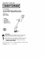
Operator's
Manual
CRAFTSMR
5 Amp Motor
14 Inch Cutting Path / 0,065 In. Line
ELECTRIC
WEEDWACKER
®
Model No.
358.745460
•
Safety
•
Assembly
•
°
Operation
Maintenance
•
Espar_ol, p. 16
/
J
Read
and follow all Safety Rules and Operating
WARNING:
Instructions
before first use of this product.
For
Call answers
7 am-7
•
Sears,
to your
questions
this product:
pm,
Mon-Sat;
Sun,about
10 am-7
pm
1-800-235-5878
Roebuck
545123834
(Hours
,isted
are
Central
Time)
and Co., Hoffman
Rev. 1
11/1/07
BRW
Estates,
IL 60179
U.S.A.
Warranty Statement
Identification of Safety Symbols
Safety Rules
Assembly
Operation
Maintenance
ONE YEAR FULL WARRANTY
LINE TRIMMER
2
2
4
6
9
12
Service & Adjustments
Parts Available
Storage
Troubleshooting
Table
Spanish
Parts Ordering
ON CRAFTSMAN
ELECTRIC
13
14
14
15
16
Back Cover
WEEDWACKER
®
When used and maintained according to the operator's manual, if this product fails
due to a defect in material or workmanship within one year from the date of purchase, return it to any Sears store or other Craftsman outlet in tile United States for
free replacement.
This warranty does not include the nylon line, which is an expendable part,
This warranty appties for only 30 days from purchase date if this product is used
for commercial or rental purposes,
This warranty gives you specific legal rights, and you may also have other rights
which vary from state to state,
Sears, Roebuck and Co., Roffrnan E_tates, IL 60179
@
®®
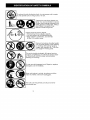
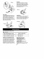
_DANGER:
Use only specified trimmer
head, spool, and 0.065 inch (1 >65 mm) recommended trimmer line. Never use blades,
flailing devices, wire, rope, string, etc. Unit is
designed for line trimmer use only. Failure to
follow these instructions may result in serious injury.
1
I&
%
I
improper
use can cause serious injury.
This unit can be dangerous!
i_WARNING:
z_ _____.H_
_WARNING:
the unit repaired
double
insul_ttion
in serious
injury,
This unit is double
by qualified
service
construction
insulated,
personnel
to become
Careless
or
Failure to have
can cause the
ineffective
and
Read the operator's manual before use< Faiture to follow
instructions could result in serious injury, Save operator's
manual
result
Toreduce
theriskofelectric
shock,
donotexpose
unittowater.
Donotoperate
unitonwetground
orinrain.
_
lently.
Youcanbeblinded
orinjured.
Always
wearhearing
protection
and
safety
g
lasses
ma_ked
Z87. Always
Trimmer
linelong
canthrow
viowear heavy,
pants, objects
long
sleeves,
boots and gloves.
Hazard zone for thrown objects.
• Trimmer line throws objects violently.
• You and others can be blinded/injured.
• Keep chitdren, bystanders, and animals
50 feet (15 meters) away.
Do not wear jewelry, loose clothing
or clothing with loosing hanging
straps, ties, tassels, etc. They can
be caught in moving parts.
_
"_11_
must be completed by an authorized service dealer. Disconnect unit from power source before
This unit is double insulated. All internal service
c ean ng or servicing.
_1
Do not use with damaged cord. Repair or replace
damaged cord immediately.
[O_1
Store unit indoors in a high, dry place out of the
reach of children. Store unit unplugged.
I1_
_
_11_
This unit is for household
I commercial use.
use only and not for
When
servicing
unit,useonlyidentical
replacement
parts<
Never
allow
children
tooperate
thisunit.
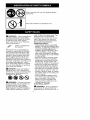
_WARNING:When
using
electric
gardening
appliances,
basic
safety
precautions
must
always
befollowed
toreduce
theriskoffire,electric
shock,
andserious
injury<
Read
and
follow
allinstructions<
mals 50 feet (15 meters) away. If approached stop unit immediately<
If situations occur which are not covered in this manual, use care and
good judgement. If you need assistance, call 1-800-235-5878.
OPERATOR SAFETY
• Dress properly< Always wear safety
glasses or similar eye protection when
operating, or performing maintenance
on your unit< (Safety glasses are
available.) Always wear face or dust
mask if operation is dusty< Always
wear heavy, long pants, tong sleeves,
boots, and gloves. Do not go barefoot
or wear sandals<
• Secure hair above shoulder length.
Secure or remove loose clothing
and jewelry or clothing with loosely
hanging ties, straps, tassels, etc.
They can be caught in moving parts.
• Being fully covered also helps protect you from debris and pieces of
toxic plants thrown by spinning line>
• Stay alert. Do not operate unit when
you are tired, ill, upset or under influence of alcohol, drugs, or medication. Watch what you are doing; use
common sense.
• Avoid unintentional starting of the
unit. Never carry unit with your finger on the switch< Be sure the
switch is in the OFF position and
never touch the switch when connecting extension cord.
ELECTRICAL
SAFETY
SAFETY
INFORMATION
.
ON THE UNIT
This power unit can be dangerous!
Operator is responsible for following
the warnings and instructions in this
manual and on the unit, Read entire
operator's manual before using unit!
Be thoroughly familiar with the controis and the proper use of the unit<
Restrict the use of this unit to persons
who read, understand, and follow unit
and manual warnings and instructions. Never allow children to operate
this unit. Close attention is necessary
when used near children.
DANGER:
Never use blades or
flailing devices. Unit is designed for
line trimmer use only. Use of any other
accessories or attachments will increase the risk of injury.
®®®@
_WARNING:
Trimmer line throws
objects violently. You and others can
be blinded/injured.
Wear safety
glasses, boots, and leg protection,
Keep body parts clear of rotating line,
Keep children, bystanders, and ani-
_
WARNING:
Avoid a dangerous
environment.
To reduce the risk of
electrical shock, do not use in rain, in
4
• Donotusetheunitiftheswitch
does
damp
orwetlocations,
oraround
swimming
pools,
hottubs,
etc.Donot
notturntheunitonandoffproperly.
expose
tosnow,
rain,orwater
toavoid Repairs
totheswitch
must
bemade
thepossibility
ofelectrical
shock.
byyourauthorized
service
dealer.
• Useavoltage
supply
asshown
on
• Keep
theextension
cordclearofopunit.
erator
andobstacles
atalltimes.Do
• Avoid
dangerous
situations.
Donot
notexpose
cords
toheat,
oil,water,
useinthepresence
offlammable
orsharp
edges.
liquids
orgases
toavoidcreating
a
• Toavoid
thepossibility
ofelectric
fireorexplosion
and/or
causing
shock,
avoid
body
contact
withany
damage
tounit.
grounded
conductor,
suchasmetal
• Toreduce
theriskofelectrical
shock, fences
orpipes.
tillsequipment
hasa polarized
plug
• Ground
Fault
Circuit
Interrupter
(one
blade
iswider
thantheother)
(GFCl)
protection
should
beprovided
o
ncircuit
oroutlet
tobeused.
andwillrequire
theuseofapoladzed
extension
cord.
Theappliance
plug
Receptacles
areavailable
having
willfitintoapolarized
extension
cord
built-in
GFClprotection
andmaybe
onlyoneway.
Iftheplugdoes
notfit
used
forthismeasure
ofsafety.
fullyintoti_e
extension
cord,
reverse UNIT SAFETY
tileplug.Iftheplugstiltdoes
notfit,
• Inspect unit before use. Replace
obtain
acorrect
polarized
extension damaged parts. Make sure all hancord.
Apolarized
extension
cordwitl
dles, guards, and fasteners are in
require
theuseofapoladzed
watlout- place and securely fastened. Parts
let.Thisplugwillfitintothepolarized that are damaged must be repaired
walloutlet
ontyoneway.
Ifplugdoes
or replaced by an authorized service
notfitfullyintothewatloutlet,
reverse dealer These include head parts that
tileplug.
Ifitstilldoes
notfit,contact
a
are cracked, or chipped, guards,
qualified
electrician
toinstall
theprop- and any other part that is damaged.
erwalloutlet.
Donotchange
the
• Do not repair unit yourself.
equipment
plug,
extension
cordre• Use only 0.065 inch (1.65 mm) diameter recommended
trimmer line
ceptacle,
orextension
cordplugin
anyway.
(see USER REPLACEABLE SERVICE
• Toreduce
riskofelectrical
shock,
use
PARTS in the SERVICE AND ADJUSTextension
cords
specifically
marked
MENTS section). Never use wtie,
assuitable
foroutdoor
appliances
rope, string, etc.
having
electdcat
rating
nottess
than
• Use specified trimmer spool. Make
therating
ofunit.Cord
must
be
sure spool is properly installed and
marked
withsuffix
"W-A"
(inCanada all parts are securely fastened.
'M/").
Make
sure
yourextension
cord • When servicing unit, use only
isingoodcondition.
Inspect
extension Craftsman identical replacement parts
and accessories as recommended.
cordbefore
useandreplace
ifdamaged.
Donotuseadamaged
cord.
CUTTING SAFETY
Cord
insulation
must
beintact
withno
Inspect areato be
cracks
ordeterioration.
Plug
connec- _WARNING:
torsmust
beundamaged.
Anunder- cut. Remove objects (rocks, broken
sized
extension
cordwillcause
adrop glass, nails, wire, string, etc.) which
inlinevoltage
resulting
intossofpow- can be thrown or become entangled in
erandoverheating.
Ifindoubt,
use
cutting head.
thenextheavier
gauge.
Thelower
the • Do not overreach or stand on unstagauge
number,
theheavier
thecord
ble support. Keep firm footing and
balance.
(see
SELECT
ANEXTENSION
CORD
in
theOPERATION
section).
• Keep the cutting head below waist
level. Do not raise handles above
• Donotusemultiple
cords.
• Donotabuse
cord.
Never
carry
the
your waist. Cutting head can come
unitbytileextension
cord
oryankexdangerously close to your body.
tension
cordtodisconnect
unit.
• Keep away from cutting head and
• Usecordretainer
toprevent
discon- spinning line.
nection
ofextension
cordfromunit
• Use unit properly. Use only for trimandpossible
damage
totheunitdue
ming, scalping, and mowing. Do
toptugmovement
(seeATTACH
THE
not force unit. It will do the job better
EXTENSION
CORD
TOYOUR
TRIMand with tess risk of injury at the rate
MER
intheOPERATION
section).
for which it was designed.
• Useonlyindaylight
oringoodartificiallight.
MAINTENANCE
SAFETY
_WARNING:
Disconnect
unit
from the power supply before performing maintenance, or when changing
trimmer line.
• Maintain unit according to recommended procedures. Keep cutting
line at proper length. Follow instructions for changing trimmer line.
• Have all service and maintenance
not explained in this manual performed by an authorized service
dealer to avoid creating a hazard.
• Never douse or squirt the unit with
water or any other liquid. Clean unit
and labels with a damp sponge.
Keep handles dry, clean, and free
from oil and grease.
• Keep the air vents clean and free of
debris to avoid overheating the motor. Clean after each use,
TRANSPORTING
AND STORAGE
• Stop the unit and disconnect the
power source when not in use.
• Carry the unit with motor stopped.
• Store unit indoors in a high, dry
place out of the reach of children.
Store unit unplugged.
• Do not hang unit so that the trigger
switch is depressed.
CARTON CONTENTS
Check carton contents against the following list.
Model 388.745460
• Trimmer
• Shield
• Assist handle
• Wheel
Examine parts for damage. Do not
use damaged parts.
NOTE: tf you need assistance or find
parts missing or damaged, call
1-800-235-5878.
ASSEMBLY
_WARNING:
If received
DOUBLE INSULATION
CONSTRUCTION
This unit is double insulated to help
protect against electric shock. Double
insulation construction consists of two
separate "layers" of electrical insulation instead of grounding. Tools built
with this insulation system are not intended to be grounded. No grounding
means is provided on this unit, nor
should a means of grounding be added to this unit. As a result, the extension cord used with your unit can be
plugged into any standard t20 volt
electrical outlet. Safety precautions
must be observed when operating any
electrical tool. The double insulation
system only provides added protection against injury resulting from an
internal electrical insulation failure.
_[_WARNING:
Atl electrical repairs
to this unit, including housing, switch,
motor, wires, etc., must be diagnosed
and repaired by qualified service personnel. Replacement parts for a
double insulated appliance must be
recommended
by the manufacturer. A
double insulated appliance is marked
with the words "double insulation" or
"double insulated". The symbol
(square within a square) [] may also
be marked on the appliance. Failure to
have the unit repaired by qualified service personnel can cause the double
insulation construction to become ineffective and result in serious injury.
SAVE THESE
INSTRUCTIONS
SHAFT
dle until it snaps
into place.
,
j_
as-
sembled,
review all assembly steps to
ensure your unit is properly assembled and all fasteners are secure.
ASSEMBLY
WARNING:
Ensure that the excess wire between the switch handle
and motor housing is not twisted and is
enclosed in switch handle and motor
housing during assembly of the unit.
Failure to do so may result in damage
to the wires and/or the unit or serious
injury to the operator including electrocution.
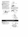
1. Push the tube into the switch han-
Tube
2. Push
thetubeintothemotor
housinguntilitsnaps
intoplace.
Motor
Housing
_'_._
I_stallatiOnrrows
3. Try to remove tube from switch handle and motor housing. If the tube
remains in place, it is propedy
snapped into place. If the tube wilt
not remain in place, repeat steps 1
and 2. Push until the tube snaps into
place.
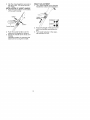
ATTACHING THE SHIELD
_WARNING:
The shield must be
properly installed. The shield provides
partial protection from the risk of
thrown objects to the operator and
others. Your unit is equipped with a
line limiter pin, which cuts excess line
to the proper length while running.
NOTE: If shield is not properly
installed, damage to unit (including motor failure) will result,
1. Place the shield onto the motor
housing. Ensure the cutting head remains free to rotate and the line is
not caught between the shield and
the motor housing (see illustration).
Motor Housing
Line Limiter
_
_hield
2. Align the installation
arrow on the
shield with the installation
arrow on
the motor housing as shown.
3. Twist the shield as illustrated until it
snaps securely into place. Make
sure the shield is assembled to the
unit as shown in the illustration below and in the KNOW YOUR TRIMMER section of this manual.
WHEEL ASSEMBLY
1. Fit the two halves of the wheel together (see illustration).
Wheel
2, Attach the wheel to the trimmer.
Make sure the wheel is fitted into
the groove on the motor housing.
Motor
Housing
\
3.
Clip the wheel together securely on
the other side, The wheel should
turn freely,
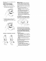
INSTALLATION OF ASSIST HANDLE
1. Press the two buttons on the sides
of the switch handle.
HEIGHT ADJUSTMENT
1. Turn height adjuster in the direction
indicated to unlock (see illustration).
,_
"- _))L
,"
/
/
/
Button
adjuster
BU_OR
Assist Handle
2.
Push the assist handle over the
buttons and release the buttons.
3. Adjust the handle to the most comfortable
operating position by pressing the
buttons and moving the handle.
2. Adjust the length of the tube to the
most comfortable operating position.
3. Turn height adjuster in the opposite direction to lock.
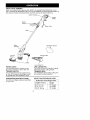
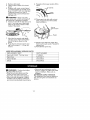
KNOW YOUR TRIMMER
READ THIS OPERATOR'S MANUAL AND SAFETY RULES BEFORE OPERATING YOUR
UNIT Compare the illustrations with your unit to familiarize yourseff with the location of
the various controls and adjustments. Save this manual for future reference.
Trigger
Switch
Assist
Motor
Housing
operator's manual
Debris Shie{d
Head
Trimmer
Wheel
Line Limiter Pin
POWER CORD
The POWER CORD is where you attach your extension cord to the unit.
TRIGGER SWITCH
The TRIGGER SWITCH is used to turn
on the unit. Squeeze the trigger switch
to operate the unit. Release to stop.
OPERATING INSTRUCTIONS
Use only a voltage suppty as specified
on your unit.
LINE LIMtTER PIN
The LINE UMITER PIN cuts the cutting
line to the proper cutting length.
TRIMMER HEAD
The TRIMMER HEAD holds cutting line
and rotates during operation,
SELECT
AN EXTENSION
Extension
CORD
Cord Gauge Chart
Length of Cord
Gauge
25 Ft. (7.5 m)
50 Ft. (15 m)
100 Ft. (30 m)
18 Gauge
15 Gauge
16 Gauge
Extension cords are available
unit at Sears.
for this
ATTACH THE EXTENSION
CORD TO YOUR TRIMMER
1. Form a toop in your extension
cord.
2. Push the loop through the slot in
the handle (see illustration).
_ WARNING:
Always wear eye
protection. Never lean over the trimmer head. Rocks or debris can ricochet or be thrown into eyes and face
and cause blindness or other serious
injury.
When operating unit, stand as shown
and check for the following:
• Wear eye protection and heavy
clothing.
• Hold trigger handle with right hand
and assist handle with left hand.
• Keep unit below waist level.
• Cut only from your right to your left
to ensure debris is thrown away
from you. Without bending over,
keep line near and parallel to the
ground and not crowded into material being cut.
AUTOMATIC
LINE FEED SYSTEM
When the trimmer is initially started, a
smalt length of cutting line is fed out.
3.
Position tile loop over the cord retainer and pull back to secure.
4. Connect power cord of unit to extension cord.
Line Limiter
Pin
After approximately 5 seconds, the
tine witl be cut to the correct length by
the line limiter pin as the motor reaches full speed. Make sure the motor i8
up to full speed before trimming. If
the noise of ti_e cutting line being cut
cannot be heard, more line will need to
be fed out.
CORRECT
Trimming
OPERATING
POSITION
Edging
To feed more line:
• Allow the motor to stop completely;
then, restart the motor and allow it to
reach full speed.
• Repeat until you hear the line hitting
against the line limiter pin (do not repeat this procedure more than 6
times).
If problems are experienced with the
automatic line feed, refer to the TROUBLESHOOTING TABLE.
To manually
feed the nylon line:
• If required, the cutting line can be
fed out manually.
• To operate, press and release
manual line feed button while gently
_inUllingon one of the lines until the
e reaches the line limiter pin.
10
• When the required amount of line is
fed out, gently pull on the second
line (there is no need to press the
manual line feed button again).
• If the line extends past the line limiter pin, too much line has been fed
out. If too much line is fed out, remove the spool cap and click spool
counterclockwise
until the tine is at
the desired length.
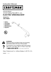
To remove 8pool cap:
1. Press and hold in the two cap release latches.
2. PuIt cap away from the hub.
o_
Spo
Hub _
Cap
Cap
release
ch
mIWARNING:
Use only 0.065 inch
(1.65 mm) diameter line. Other sizes of
line will not advance properly and wilt
result in improper cutting head function
or can cause serious injury. Do not use
other materials such as wire, string,
rope, etc. Wire can break off during cutting and become a dangerous missile
that can cause sedous injury. See page
4 for warning concerning other cutting
devices.
TRIMMING
Hold the bottom of the trimmer head
about 3 inches (8 cm) above the
ground and at all angle. Allow only the
tip of the line to make contact. Do not
force trimmer line into work area.
above ground
EDGING POSITION
You can twist the lower portion of the
unit into an edging position. Press button and twist lower portion of unit as
shown in the illustration until it snaps
into place. To return to trimming position, press button and twist lower portion in opposite direction.
Eyelet
To reinstall _pool cap:
1. Keep all areas of the cap and hub
clean. Failure to do so may prevent
the cap being securely located in
the hub.
2. Replace the cap, pressing firmly
down towards the hub to ensure
cap is fully secured.
3. Check that the cap is secure by
trying to remove it without pressing
the two latches.
EDGING
While edging, allow unit to rest on
wheel for extra stability. Edge in direction shown in illustration. Allow the tip
of the line to make contact. Do not
force the line. Take extra caution while
edging as objects can be thrown from
the trimmer line.
11
MOWING
Your trimmer is ideai for mowing in
places conventional lawn mowers
cannot reach. In the mowing position,
keep the line parallet to the ground.
Avoid pressing the head into the
ground as this can scalp the ground
and damage the tool.
Edging
Mowing
Direction
SCALPING
The scalping technique removes unwanted vegetation down to the ground.
Hold the bottom of the trimmer head
about 3 inches (8 cm) above the
ground and at an angle. Allow the tip of
the line to strike the ground around
trees, posts, monuments, etc. This technique increases line wear.
so,lpi, g I
CUSTOMER
SWEEPING
The fanning action of the rotating line
can be used for a quick and easy
clean up. Keep the line parallel to and
above the surfaces being swept and
move the toot from side to side.
g
RESPONSIBILITIES
WARNING:
Disconnect
power source before performing
maintenance.
CARE & MAINTENANCE
TASK
WHEN TO PERFORM
Check for loose fasteners
and parts
Before each use
Check for damaged
or worn pa_ts
Before each use
Inspect and clean unit and labels
GEN ERAL RECOM MENDATIONS
The warranty on this unit does not
cover items that have been subjected
to operator abuse or negligence, To
receive full value from the warranty,
the operator must maintain unit as
instructed in this manual, Various adjustments wilt need to be made periodically to properly maintain your unit,
After each use
BEFORE
EACH USE
CHECK FOR LOOSE
FASTENERS AND PARTS
• Housing Screws
• Debris Shield
CHECK FOR DAMAGED
OR
WORN PARTS
Contact a Sears Service Center for
replacement of damaged or worn
parts.
12
• Trigger Switch - Ensure switch functions properly by pressing and releasing the trigger switch. Make sure
motor stops.
• Debris Shield - Discontinue use of
unit if debris shield is damaged.
AFTER
EACH USE
INSPECT AND CLEAN UNIT AND LABELS
• After each use, inspect complete
unit for loose or damaged parts.
Never use a damaged trimmer.
• Clean the unit using a damp cloth
with a mild detergent.
• Wipe off unit with a clean dry cloth.
• Use a soft brush to clean around the
inside of the debris shield, the cutting head and the motor housing air
vents.
REPLACING
'_
fu
Air Vents
• Remove the wheel by pressing
one
of the buttons. Clean the wheel and
groove on the motor housing with a
soft brush. Reinstall wheel (see ASSEMBLY section).
THE LINE
Cap
_WARNING:
Disconnect
unit
from power source before servicing.
1. Press and hold in the two cap release latches.
2. Pult cap away from the hub.
Spool
Hub _
13
Cap
release
latch
Eyelet
9, Repeat on the lower section of the
spool.
3.
4.
Remove old spool.
Clean entire surface of hub and
spool.
5. Replace with a pre-wound
spool
or cut two lengths of 13 feet (4 meters) of 0.085" (1.85 mm) diameter
Craftsman brand line. Use of
heavier lines could overioad and
damage unit.
Notches
Ai_WARNING:
Never use wire,
rope, string, etc., which can break off
and become a dangerous missile.
6. Insert one end of the line about 1/2
inch (I cm) into one of the small
holes in the upper section of the
inside of the spool.
lO.Ptace spool into hub with cut out
area of spool in line with eyelets
(see illustration).
\
Cut out
area of spool
7. Wind the line evenly and tightly
onto the spool. Wind in the direction of the arrow found on the
spool.
8. Push the line into the notch, leaving 3 to 5 inches (7 - 12 cm) unwound.
USER REPLACEABLE
REPLACEMENT
Spool with 0.065"
SERVICE
11. Remove one line from notch and
feed line through eyelet. Repeat for
second line.
12. Reinstall the spool cap.
PARTS
PART
PART NUMBER
71-85935
Trimmer Line
Spool Cap
Assist Handle
545124417
Wheel
545124405
_WARNING:
545124404
Perform
the follow-
ing steps after each use.
• Stop the unit and disconnect the
power source when not in use.
• Carry the unit with motor stopped.
• Store unit with all guards in place.
Position unit so that any sharp object cannot accidentally cause injury.
• Store unit and extension cord indoors in a high, dry place out of the
reach of children. Store unit unplugged.
EXTENSION CORD STORAGE
The extension cord can be stored on
the unit using the cord brackets as
shown.
14
1. Wind cord carefully to avoid kinking.
2. To release the cord, press the button and the bracket will drop down
(see illustration).
Bracket
3.
TROUBLESHOOTING
Push cord bracket fully back into
position.
TABLE
_WARNING:
Always stop unit and disconnect from the power source before
performing all of the recommended remedies below except remedies that require
unit to be operating.
TROUBLE
Trimmer head
stops under a
load or does not
turn when switch
is pressed
Line does not
advance, line is
too short, or
trimmer vibrates.
Excessive noise
when unit is running.
CAUSE
1. Crowding trimmer line
against material being
cut.
2. Electdcal failure.
3. Thrown circuit breaker.
4+ Debris stopping head.
1. Line improperly routed
in head.
2. Line improperly
wound into spool.
3. tncorrect line size
4. Not enough line
outside of head.
5. Manual line feed not
working.
6. Dirt buildup on unit.
1. Motor has not reached
full speed before use.
2. Too much line has been
released from the spool.
3. Line limker pin missing
from shield.
REMEDY
1. Aflow tip of tine to do the cutting.
2. Contact Sears Service
3. Check Breaker Box.
4. Remove debris.
(see back cover).
1. Check line routing
2. Rewind line tightly and evenly
3. Use only 0.065 in. (1.65 mm) din. line
4. Remove spool cap and spool. Manually
feed tine. Reinstatl cap and spool. See
Automatic Line Feed System section.
5. Rewind line tightly and evenly. Check
that line is in correct section of spool.
6. Clean unit.
1. Allow the motor to reach full speed
before use.
2. Rewind line tightly and evenly. See
Automatic Line Feed System section.
3. Contact Sears Service (see back cover).
Line releases
continuously,
1+ Line improperly
routed in head.
2. Spool damaged.
1. Check line routing.
Line usage is
excessive,
1 Une improperly routed
in head.
2. Une size is incorrect.
3 Crowding line against
material being cut.
4 Spool worn or damaged.
1. Check line routing.
1. Dirt or debris buildup
on wheel or in groove
1. Clean wheel and groove on motor
housing (see Maintenance
section).
Wheel stops
turning,
2. Replace spool.
2. Replace spook
3. Cut with tip of _ine fully extended.
4-. Replace spool.
15