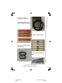
1
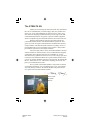
SEARCH KIT Manual
page 1
Tuesday, March 26, 2002 13:14
Composite
The STEALTH Kit
Thank you for choosing the American made, SGC STEALTH
Kit. We are confident that you will be happy with your purchase and
assure you of our full commitment to customer service. Since 1971,
SGC has been designing and manufacturing a wide range of HF SSB
communications products. Our goal is to provide reliable equipment,
which is competitively priced and which fits the need of the radio user.
With the STEALTH Kit, SGC has provided an all-in-one,
convenient antenna solution. The STEALTH Kit is perfect for emergency use, when an urgent communications command center must be
setup in minutes. The STEALTH Kit contains everything a novice or
professional needs to erect an antenna in any location—and provides
performance equivalent to most dipole antennas!
And, in keeping with its’ name, the STEALTH Kit is an ideal
antenna solution for restricted areas, such as condominiums and gated
communities where dipoles and towers are forbidden. Or, use the
STEALTH in city apartments where access to roofs or large open areas
is restricted. The STEALTH Kit is also a great antenna solution when
you are on vacation. Whether in an RV or a hotel room, the STEALTH
Kit is a “Grab and Go” box - filled with everything you need to complete your communications center.
We are proud of the STEALTH Kit as it provides an antenna
system that is automatic, easy to install and easy to use. Any location,
any radio and any situation - the STEALTH Kit is the perfect choice
for a quick and convenient antenna solution.
Pierre Goral
President
KI7UA
SEARCH KIT Manual
page 2
Tuesday, March 26, 2002 13:14
Composite
Table of Contents
Quick Start............................................................. 4
1.0 Introduction ....................................................... 5
2.0 Specifications.................................................... 6
3.0 Supplied Items .................................................. 7
4.0 Installation......................................................... 7
4.1 Advance preparation for emergency use........... 7
4.1 Antenna Installation .......................................... 8
4.1.1 Antenna Orientation ....................................... 8
4.1.1.1 Horizontal - for less than 500 miles ............. 9
4.1.1.2 Vertical - for more than 500 miles.............. 10
4.1.2 Shape of the antenna loop ........................... 10
4.1.3 Antenna Directivity ....................................... 10
4.1.4 Height of antenna......................................... 11
4.1.5 Inside or outside........................................... 11
4.1.6 Environment................................................. 11
4.2 So what should I do?....................................... 11
4.2.1 One Loop Configurations ............................. 12
4.2.2 Two Loop Configurations ............................. 13
4.2.3 Three Loop Configurations........................... 14
4.2.4 Four Loop Configurations............................. 14
4.2.5 Coupler Connection Point ............................ 14
4.3 Sample Installation.......................................... 15
4.4 SG-237 Smartuner Coupler Installation........... 19
4.5 Tips: Do’s & Don’ts ......................................... 19
5.0 Adjustable Directive Loop Antenna ................. 21
5.1 Antenna Setup with Four Brooms.................... 25
5.2 General Applications....................................... 27
6.0 SGC Limited Product Warranty ....................... 29
7.0 Appendix......................................................... 30
8.0 Global Reference Database ............................ 38
9.0 Conclusion ...................................................... 38
10.0 Further Reading ............................................ 39
11.0 Special Thanks ............................................. 39
Mailing: PO Box 3526, Bellevue, WA 98009
Shipping: 13737 SE 26th St., Bellevue, WA 98005
Toll-Free: 800-259-7331 • Phone 425-746-6310 • Fax: 425-746-6384
www.sgcworld.com • Email: [email protected]
SEARCH KIT Manual
page 3
3
Tuesday, March 26, 2002 13:14
Composite
Quick Start
1.
2.
3.
4.
5.
6.
7.
Locate a proper area where you would like to erect your loop
antenna. Initially the system could be operated with the antenna
lying on the floor.
Connect your coupler to the transceiver and a suitable 12VDC
power supply. This can be the same source as the power supply to
the radio if it is a 12VDC unit. Avoid regulated linear or switching power supplies as they may be susceptible to RF radiation
and may lose regulation and apply higher voltage than permissible. Power supplies may also lose regulation at peak modulation
and cause intermittent operation.
Connect your loop antenna to the two terminals of the coupler;
one hot side, one ground side. Both have a wing nut terminal to
allow easy attachment.
If urgent operation is required, transmit on an emergency frequency with the antenna on the ground. Although this setup is not
efficient, it will allow you to easily establish a communication
link in an emergency.
Configure your antenna in single or multiple loops (not to exceed
four loops).
Elevate your system to any surrounding high points such as a
tree, roof, top of car, ceiling, mast, etc. Attach with 4 ropes and
clips provided. The coupler can also be elevated using the fifth
piece of rope.
After your initial contact, you may improve your antenna installation following the guidelines in this manual.
Mailing: PO Box 3526, Bellevue, WA 98009
Shipping: 13737 SE 26th St., Bellevue, WA 98005
Toll-Free: 800-259-7331 • Phone 425-746-6310 • Fax: 425-746-6384
www.sgcworld.com • Email: [email protected]
4
SEARCH KIT Manual
page 4
© March 2002 - SGC, Inc.
Tuesday, March 26, 2002 13:14
Composite
1.0 Introduction
The Smart Tuning, Emergency Antenna Loop, Tactical HF Kit STEALTH - antenna kit is a high-frequency antenna for situations
where a full size antenna is not possible. Its main features are:
•
•
•
•
•
•
•
Easily configured to the space available
Groundless - no RF ground required
Easy to install - kit contains all necessary items
Automatic operation
Easy to use - no meters or lights to watch, no buttons to
push
Wide bandwidth - 2.5 (and lower for non-amateur radio
usage) to 30 MHz
High performance - can match the performance of a full
size dipole
STEALTH is a loop antenna chosen for its radiation efficiency and
because it does not require an electrical ground. It can be horizontal or
vertical mounted for short and long range communications needs.
An important use of STEALTH is as an emergency antenna.
STEALTH is easy to install and easy to operate. Its small size makes
it easy to transport and quick to install.
But STEALTH was also designed for...
The amateur radio user who is struggling with Homeowners’
“Covenants, Conditions & Restrictions”. A stealth antenna can be
installed with no visible signs of its presence, in developments where
erected antennas are forbidden.
Those living in an apartment or similar limited environment.
STEALTH provides an effective antenna in small spaces. It can be
installed in an area as small as 5 feet by 5 feet.
Use as an effective, ready to go, compact vacation antenna.
Offices, farms, etc. It can be used where other antennas are not practical.
Mailing: PO Box 3526, Bellevue, WA 98009
Shipping: 13737 SE 26th St., Bellevue, WA 98005
Toll-Free: 800-259-7331 • Phone 425-746-6310 • Fax: 425-746-6384
www.sgcworld.com • Email: [email protected]
SEARCH KIT Manual
page 5
5
Tuesday, March 26, 2002 13:14
Composite
1.1 Disclaimers
RF Burns can occur if the output terminals or antenna wire of the SG237 are touched while transmitting. Use caution to avoid injury and
burns.
Prolonged exposure to RF should be avoided. Those persons using
heart pacemaker devices should avoid RF exposure.
To avoid injury and damage to equipment: Whenever possible, we
strongly recommend reducing transmit power. Preferably, 10 to 25
watts should be used and will generally provide good communications. If using an outside antenna, 100 watts can be used without any
harmful consequences.
If for any reason a particular setup or frequency does not provide the
expected results, minor changes can significantly improve performance. For example: move the radio as far away as possible from the
coupler or antenna; avoid coiled power or coaxial feed cables; reconfigure setup, etc.
SGC accepts no responsibility for performance or results from the
STEALTH Kit. SGC accepts no responsibility for any unlikely damage or injury resulting from the use of the STEALTH Kit.
2.0 Specifications
•
•
•
•
•
•
•
•
Antenna loop perimeter: 80’ (24m)
Maximum square configuration - 20’ (6.1m)
Minimum square configuration - 5’ (1.5m)
Number of turns - 1 to 4
HF frequency range - 2.5 to 60 MHz.
Maximum power - 100 watts
Package size 3.5” x 10” x 15” (8.9cm x 25.4cm x 38.1cm)
Package Weight 5lbs. (2.3kg)
Mailing: PO Box 3526, Bellevue, WA 98009
Shipping: 13737 SE 26th St., Bellevue, WA 98005
Toll-Free: 800-259-7331 • Phone 425-746-6310 • Fax: 425-746-6384
www.sgcworld.com • Email: [email protected]
6
SEARCH KIT Manual
page 6
© March 2002 - SGC, Inc.
Tuesday, March 26, 2002 13:14
Composite
Performance and results may vary and SGC does not warrant any installation or any result. SGC reserves the right to change the specifications without notice.
3.0 Supplied Items
•
•
•
•
•
•
SG-237 Smartuner HF Antenna coupler and manual.
80’ (25m) of loop antenna wire.
4 - antenna mounting clips and 20’ (6m) ropes attached
30’ (9.14m) of nylon support rope with clip
12 - Releasable cable ties
2 - spare antenna mounting clips
4.0 Installation
4.1 Advance Preparation for emergency use
Plan your emergency station before you need it! You should consider
things like:
Mailing: PO Box 3526, Bellevue, WA 98009
Shipping: 13737 SE 26th St., Bellevue, WA 98005
Toll-Free: 800-259-7331 • Phone 425-746-6310 • Fax: 425-746-6384
www.sgcworld.com • Email: [email protected]
SEARCH KIT Manual
page 7
7
Tuesday, March 26, 2002 13:14
Composite
•
•
•
•
Equipment - Have you selected the equipment to be used
in an emergency situation? Is that equipment able to
withstand possible abuse? Do you have all power
sources immediately available and, in the case of batteries, are they fully charged?
Cable extensions - Do you have AC cords long enough
for typical situations? Is your coax long enough or
should you have some extensions? If your installation
will be battery powered, do you have cables to reach
them and also the cables needed to maintain the charge
on them?
Connector installation(s) - Have you installed all connectors on all the cables which might be needed?
Where are your emergency supplies - Are they in one,
quickly retrievable location? Or do you have them scattered around?
Do not wait for an emergency to happen - be ready. Test
everything including STEALTH. Be fully prepared to react
in the event of an emergency.
4.1 Antenna Installation
There are several factors which need to be considered before installing the antenna and some can affect others.
WARNING!
Never mount any antenna near power lines or utility wires. Any
materials, ladders, ropes, feedlines, etc., which come in contact
with power lines can conduct voltages that can be fatal.
Stay away from all power lines.
4.1.1 Antenna Orientation
Because the signal radiation of a loop antenna is perpendicular to the
plane of the loop, how you orient the antenna should be determined
by your communication needs.
Mailing: PO Box 3526, Bellevue, WA 98009
Shipping: 13737 SE 26th St., Bellevue, WA 98005
Toll-Free: 800-259-7331 • Phone 425-746-6310 • Fax: 425-746-6384
www.sgcworld.com • Email: [email protected]
8
SEARCH KIT Manual
page 8
© March 2002 - SGC, Inc.
Tuesday, March 26, 2002 13:14
Composite
This is called polarization. A loop mounted horizontally is considered
to be vertically polarized as the signal is primarily radiated vertically
and will provide more effective short distance communications. Likewise, a loop mounted vertically is horizontally polarized as its signal
is primarily radiated horizontally and is better for long range communications.
4.1.1.1 Horizontal - for less than 500 miles
(830km)
If your needs are expected to be less than 500 miles (830km), the best
results can be obtained by orienting the antenna so the plane of the
loop is horizontal.
Horizontal triangular plane - for vertical radiation, the coupler is
supported by rope, approx. 25 ft. in the center of the back segment.
Mailing: PO Box 3526, Bellevue, WA 98009
Shipping: 13737 SE 26th St., Bellevue, WA 98005
Toll-Free: 800-259-7331 • Phone 425-746-6310 • Fax: 425-746-6384
www.sgcworld.com • Email: [email protected]
SEARCH KIT Manual
page 9
9
Tuesday, March 26, 2002 13:14
Composite
4.1.1.2 Vertical - more than 500 miles
(830km)
Use this type of antenna when you need to maintain long range communications of 500 to 5000 miles (830km to 8300km).
Vertically mounted two-turn
loop. The coupler is installed in
center of lower section antenna.
4.1.2 Shape of the antenna loop
The ideal shape of the antenna for
this situation would be a single turn
circle. However, this would require
complicated mounting.
Most needs can be fulfilled with a
one-turn square, rectangle or triangle shape. When there are limitations on what the size and shape of
the loop can be, it might be necessary to reduce the size by making
the loop two, three or four turns.
4.1.3 Antenna directivity
Like any antenna, a loop antenna is directional. As the size of the loop
is reduced, by configuring it as two, three or four turns, the directivity
becomes more significant.
10
SEARCH KIT Manual
page 10
Mailing: PO Box 3526, Bellevue, WA 98009
Shipping: 13737 SE 26th St., Bellevue, WA 98005
Toll-Free: 800-259-7331 • Phone 425-746-6310 • Fax: 425-746-6384
www.sgcworld.com • Email: [email protected]
© March 2002 - SGC, Inc.
Tuesday, March 26, 2002 13:14
Composite
4.1.4 Height of antenna
As is the case with all antennas, the rule of thumb is “the higher the
better”. You should attempt to make the lowest point of the loop at
least 10 feet (3mtr) above ground.
4.1.5 Inside or outside
If possible, the antenna should be located outside and clear of any
structures for maximum effectiveness. If you find this impossible, and
you must locate the antenna inside, consider the following:
• Ensure that the antenna will be at least 4 inches (10cm.)
away from any larger metal objects such as a corner
column or window support.
• Does the ceiling or roof of the room contain metal material? This can have a negative effect on the performance
of the antenna.
• Is there any metal within the outside walls of the building? This can also have a negative effect.
4.1.6 Environment
Your physical environment can influence how you mount STEALTH.
For example, in a rainy area, an outside mounted antenna would need
to be mounted as high as possible to avoid interaction with the wet
ground. In a desert, where it is dry, this would be less of a consideration.
4.2 So what should I do?
The above descriptions are the ideal situations and may not always be
obtainable. You should make every effort to install the antenna in an
optimum way.
Although a square or rectangular antenna loop is generally more effective, a triangular loop can also be used. If necessary, shape the antenna as two-turn or three-turn loop and lay it on an inside floor. It
will not be as efficient as possible but you should be able to conduct
effective communications.
Mailing: PO Box 3526, Bellevue, WA 98009
Shipping: 13737 SE 26th St., Bellevue, WA 98005
Toll-Free: 800-259-7331 • Phone 425-746-6310 • Fax: 425-746-6384
www.sgcworld.com • Email: [email protected]
SEARCH KIT Manual
page 11
11
Tuesday, March 26, 2002 13:14
Composite
The sketches below show possible shapes.
One Loop Configurations
Configuration 101
Configuration 102
Configuration 103
These configurations are the most common and
are used for installations outside and away from buildings.
12
SEARCH KIT Manual
page 12
Mailing: PO Box 3526, Bellevue, WA 98009
Shipping: 13737 SE 26th St., Bellevue, WA 98005
Toll-Free: 800-259-7331 • Phone 425-746-6310 • Fax: 425-746-6384
www.sgcworld.com • Email: [email protected]
© March 2002 - SGC, Inc.
Tuesday, March 26, 2002 13:14
Composite
Two Loop Configurations
Configuration 201
Configuration 202
Configuration 203
The two turn loop is primarily used for inside situations. It is also a
very convenient installation for vacationing, a small patio, or even a
greenhouse.
Mailing: PO Box 3526, Bellevue, WA 98009
Shipping: 13737 SE 26th St., Bellevue, WA 98005
Toll-Free: 800-259-7331 • Phone 425-746-6310 • Fax: 425-746-6384
www.sgcworld.com • Email: [email protected]
SEARCH KIT Manual
page 13
13
Tuesday, March 26, 2002 13:14
Composite
Three Loop Configurations
Configuration 301
Configuration 302
Four Loop Configurations
Configuration 401
Configuration 402
The three and four turn loops are almost always indoor antennas and
are very convenient for situations where there is a limited amount of
space available. This will be of significant importance for the office or
apartment user where they can be mounted near a window or door.
Coupler Connection Point
In the case of the triangular configurations above, the coupler is
shown connected at a mid point of one of the legs which is the suggested point. If necessary, it can also be connected at a corner of the
triangle. Testing has shown that the corner connection performs better
when the coupler is connected at a midpoint of one of the legs or segments. (Configurations 501, 502 & 503 will perform better than 302
& 402.)
14
SEARCH KIT Manual
page 14
Mailing: PO Box 3526, Bellevue, WA 98009
Shipping: 13737 SE 26th St., Bellevue, WA 98005
Toll-Free: 800-259-7331 • Phone 425-746-6310 • Fax: 425-746-6384
www.sgcworld.com • Email: [email protected]
© March 2002 - SGC, Inc.
Tuesday, March 26, 2002 13:14
Composite
Configuration 502
Configuration 501
Configuration 503
Tip: one drawback when connecting the coupler at a corner of a triangular configuration is that the support ropes for the coupler can
become long and difficult to install properly.
If you have obtained the STEALTH for emergency use, practice
installing the antenna. This will benefit you when it comes to an
actual emergency situation.
4.3 Sample installation
WARNING!
Never mount any antenna near power lines or utility wires. Any
materials, ladders, ropes, feedlines, etc., which come in contact
with power lines can conduct voltages that can be fatal.
Stay away from all power lines.
For the limited space available, a three-turn square loop antenna,
mounted vertically, for long range communication needs, is to be assembled with the coupler resting on the floor.
This will show how to construct the antenna so that emergency operations can begin as quickly as possible. You will then be shown how to
finish the installation for better performance.
Mailing: PO Box 3526, Bellevue, WA 98009
Shipping: 13737 SE 26th St., Bellevue, WA 98005
Toll-Free: 800-259-7331 • Phone 425-746-6310 • Fax: 425-746-6384
www.sgcworld.com • Email: [email protected]
SEARCH KIT Manual
page 15
15
Tuesday, March 26, 2002 13:14
Composite
•
•
Form the antenna wire into the approximate desired shape and
size and slightly knot the ends of the wire together for later attaching to the coupler.
Attach four support ropes at corners of antenna using the supplied
antenna clips. The wires will easily snap into the clips.
The two loops of
the antenna
wire have been
strapped into a
support clip.
•
Raise the antenna as much as possible and secure the ropes.
The antenna,
which was
formed on the
floor, is being
raised to its
final position.
•
Secure the lower corners of the antenna.
16
SEARCH KIT Manual
page 16
Mailing: PO Box 3526, Bellevue, WA 98009
Shipping: 13737 SE 26th St., Bellevue, WA 98005
Toll-Free: 800-259-7331 • Phone 425-746-6310 • Fax: 425-746-6384
www.sgcworld.com • Email: [email protected]
© March 2002 - SGC, Inc.
Tuesday, March 26, 2002 13:14
Composite
In this sample installation, the
support ropes were attached to
2 chairs.
•
Attach the coupler to ends of antenna wire and lay it on the floor.
The antenna has been
raised to its final position and ends have
been connected to the
coupler which is lying
on the floor.
•
Attach the cable from the coupler to the radio and connect the
coupler power leads - see section 4.4.
Do not coil any cables! Doing so can make them susceptible to the
radiated signal from the antenna and they can have a negative
effect on the performance of the antenna and radio system.
At this point in the construction of the antenna, which required 15
minutes to accomplish, emergency operation is possible.
When time permits, the installation should be completed to improve
the performance of the antenna by...
•
Only in an emergency should coupler be hung by antenna wire. A
30 foot rope has been provided to support the coupler mechanically and provide relief to the antenna wire. Attach a section of
rope through mounting holes on each side of the coupler.
Mailing: PO Box 3526, Bellevue, WA 98009
Shipping: 13737 SE 26th St., Bellevue, WA 98005
Toll-Free: 800-259-7331 • Phone 425-746-6310 • Fax: 425-746-6384
www.sgcworld.com • Email: [email protected]
SEARCH KIT Manual
page 17
17
Tuesday, March 26, 2002 13:14
Composite
A support rope
has been passed
through the
mounting holes
of the coupler.
And secure the ropes so the coupler is supported.
•
The corners of the antenna loop located near the floor can be
raised.
The lower corners of the antenna have been
attached to two
chairs which are
then moved to
form the antenna into its
final shape.
The test results of this three-turn vertically mounted antenna can be
found in Appendix A
18
SEARCH KIT Manual
page 18
Mailing: PO Box 3526, Bellevue, WA 98009
Shipping: 13737 SE 26th St., Bellevue, WA 98005
Toll-Free: 800-259-7331 • Phone 425-746-6310 • Fax: 425-746-6384
www.sgcworld.com • Email: [email protected]
© March 2002 - SGC, Inc.
Tuesday, March 26, 2002 13:14
Composite
4.4 SG-237 Smartuner HF Antenna Coupler Installation
Read the SG-237 manual, which is included, as it provides detailed
information which can be helpful to your installation.
The coaxial connector at the end of the coupler cable can then be securely attached to the radio equipment.
The red wire should be attached to a +12 volt power source and the
black wire to ground.
4.5 Tips, Do’s and Don’ts
•
Do not coil any cables, even those which are not part of the antenna. Doing so can make them susceptible to the signal radiated
by the antenna and could impact the performance of the antenna
and the radio system.
•
If an “RF Burn” - it feels like a sting - is experienced by touching
the radio while transmitting, eliminate potential RF by grounding
the radio by attaching one or more 15 to 40 foot wires (not supplied) to the ground terminal of the radio.
•
When shaping the wire for a multi-turn antenna, it will be much
easier to accomplish if you can get another person to help. Form
the loops, them alternate shaking and gently pulling the wire until
all of the loops are the same length.
•
To verify that the antenna is radiating a signal, any 5 to 100 Watt
fluorescent light tube can be used. By moving the bulb around the
perimeter of the antenna you will find spots where the bulb lights
up indicating the presence of radiated RF power. Intensity of light
increases with power in the antenna and on lower frequencies.
Mailing: PO Box 3526, Bellevue, WA 98009
Shipping: 13737 SE 26th St., Bellevue, WA 98005
Toll-Free: 800-259-7331 • Phone 425-746-6310 • Fax: 425-746-6384
www.sgcworld.com • Email: [email protected]
SEARCH KIT Manual
page 19
19
Tuesday, March 26, 2002 13:14
Composite
For RF radiation
detection, the fluorescent tube has
been moved
around the loop
until a position was
found where the
bulb glowed.
•
Knot the ends of the supplied antenna wire together before attempting to shape or install the antenna. Once the antenna has
been raised into position, the knot can be removed and the coupler attached to the ends of the wire.
•
Whenever nylon rope is cut, the ends will quickly become unraveled. This can be eliminated by slowly warming the ends with a
small flame until the rope is melted slightly. You may use a
match or a lighter for this purpose.
•
The coupler should be supported by a section of rope passed
through its mounting holes. Do not allow it to hang unsupported
from the antenna wire.
•
When the installation of STEALTH will be a two-turn or threeturn configuration, forming the loops first will make the installation much easier to accomplish.
Appendix A (pg. 31) contains photographs of sample configurations
and performance test results.
20
SEARCH KIT Manual
page 20
Mailing: PO Box 3526, Bellevue, WA 98009
Shipping: 13737 SE 26th St., Bellevue, WA 98005
Toll-Free: 800-259-7331 • Phone 425-746-6310 • Fax: 425-746-6384
www.sgcworld.com • Email: [email protected]
© March 2002 - SGC, Inc.
Tuesday, March 26, 2002 13:14
Composite
5.0 Adjustable Directive Loop Antenna
A small, highly directive, four-turn loop antenna can be constructed
for indoor or outdoor use. The Adjustable Directive Loop Antenna
can be used in a room as small as 10 by 10 feet. It can be hung from
the ceiling with the supplied rope for orientation of the antenna for
the best receiving or transmitting signal. By listening to a station, the
operator can simply rotate the antenna for best signal strength or intelligibility.
When used indoors, appliances may cause local interferences or radio
frequency pollution which could substantially impair the incoming
signal. In this situation, the antenna can be oriented to minimize the
interference and enhance the incoming signal. Also, when reaching
the contact station, a test can be performed by asking the contact station for a signal report. Rotating the antenna in 45 degree increments
is the best way to determine the best radiation direction.
Direction of the angle is perpendicular to the plane of the antenna
with directivity gain varying from 6 to 12db for a 4-turn loop antenna.
This depends on the operating frequency - the lower the frequency the
higher the directivity.
For this construction, two wooden flagpoles, sticks or plastic plumbing tubes of 6 feet long would be required and a hookup point on the
ceiling, 7 feet or more above the ground.
The following pages describe this type of installation.
Mailing: PO Box 3526, Bellevue, WA 98009
Shipping: 13737 SE 26th St., Bellevue, WA 98005
Toll-Free: 800-259-7331 • Phone 425-746-6310 • Fax: 425-746-6384
www.sgcworld.com • Email: [email protected]
SEARCH KIT Manual
page 21
21
Tuesday, March 26, 2002 13:14
Composite
First construct the cross section of the two sticks by using the supplied rope - on the vertical stick by approximately 2 to 3 inches
above the center.
Next, use two of the supplied cable ties at the end of each pole; one
to go around the pole and to hold the other in place. Four sets of two
will be required, one set for each of the four ends of the poles.
22
SEARCH KIT Manual
page 22
Mailing: PO Box 3526, Bellevue, WA 98009
Shipping: 13737 SE 26th St., Bellevue, WA 98005
Toll-Free: 800-259-7331 • Phone 425-746-6310 • Fax: 425-746-6384
www.sgcworld.com • Email: [email protected]
© March 2002 - SGC, Inc.
Tuesday, March 26, 2002 13:14
Composite
Attach the cable ties 2 inches from three ends of the pole. For the
fourth side (the bottom), place the cable ties 14 to 15 inches from the
end of the pole. This will create a 4 by 4 foot loop approximately.
Next, on the bottom below the cable ties, attach the coupler vertically
with rope or more cable ties.
Now, attach the antenna wire to the coupler output and loop the antenna five times through the loops previously made. When completed,
attach the end of the loop antenna to the couplers ground terminal. If
any wire is left, pass it through an additional cable tie or just let it
hang from the lowest part of the loop. If the antenna ends up too short
to get to the ground terminal, remove it from the last cable tie and go
directly to the ground terminal.
Mailing: PO Box 3526, Bellevue, WA 98009
Shipping: 13737 SE 26th St., Bellevue, WA 98005
Toll-Free: 800-259-7331 • Phone 425-746-6310 • Fax: 425-746-6384
www.sgcworld.com • Email: [email protected]
SEARCH KIT Manual
page 23
23
Tuesday, March 26, 2002 13:21
Composite
This setup is an effective way to improve the connections.
Configuration 601
Note: Drawing shows construction details and is not to scale.
Rotate the antenna until the best direction is achieved. Then, secure it
with an additional rope attached to a nearby object such as a window
or door.
Note: Any materials can be used for this setup with the exception of
metal. Test performances expected are similar to the four loop antenna described on page 35.
24
SEARCH KIT Manual
page 24
Mailing: PO Box 3526, Bellevue, WA 98009
Shipping: 13737 SE 26th St., Bellevue, WA 98005
Toll-Free: 800-259-7331 • Phone 425-746-6310 • Fax: 425-746-6384
www.sgcworld.com • Email: [email protected]
© March 2002 - SGC, Inc.
Tuesday, March 26, 2002 13:21
Composite
5.1 Directive Loop Antenna Improvised
with Four Brooms
This is an example of a 15 minute improvisational setup using
wooden brooms in a very small area.
These are the steps used to install our
sample setup.
1. Tie four brooms together in a crisscross fashion using the ropes provided.
2. Loop the antenna wire around the
brooms four times. Use the bristles
to keep each loop of the wire apart.
Mailing: PO Box 3526, Bellevue, WA 98009
Shipping: 13737 SE 26th St., Bellevue, WA 98005
Toll-Free: 800-259-7331 • Phone 425-746-6310 • Fax: 425-746-6384
www.sgcworld.com • Email: [email protected]
SEARCH KIT Manual
page 25
25
Tuesday, March 26, 2002 13:21
Composite
3. Hang system from ceiling
using cable ties provided.
4. Attach tuner to antenna
wires.
5. Attach the coupler to the
lower broom.
6. Attach coupler to radio.
7. Rotate system horizontally
until the best connection is received.
26
SEARCH KIT Manual
page 26
Mailing: PO Box 3526, Bellevue, WA 98009
Shipping: 13737 SE 26th St., Bellevue, WA 98005
Toll-Free: 800-259-7331 • Phone 425-746-6310 • Fax: 425-746-6384
www.sgcworld.com • Email: [email protected]
© March 2002 - SGC, Inc.
Tuesday, March 26, 2002 13:21
Composite
5.2 General Applications
Most of the loop antennas described can be used anywhere, on board
boats, aircraft and cars.
Vessel
Groundless
Loop
For example,
the loop antenna can be
configured on
a sail boat
from the top
Radiation of the mast to
the front or
back of the
vessel, with
the coupler
Coupler
located on the
deck avoiding
installation of
expensive
backstay isolators.
Lower mast connection
to coupler RF ground
Fixed Wing Aircraft
Wire goes to
On an airplane the
the coupler
Isolator
antenna could be
Wire antenna
configured using a
Ground Coupler
single or multi-loop
triangular configuration from the
Wire antenna
cockpit to the top Aviation
Isolator
Radio
of the tail. Antenna control
head
wire supplied could
be replaced by
stronger bronze phosphorus cables (for airplanes faster than 80 miles
per hour).
Mailing: PO Box 3526, Bellevue, WA 98009
Shipping: 13737 SE 26th St., Bellevue, WA 98005
Toll-Free: 800-259-7331 • Phone 425-746-6310 • Fax: 425-746-6384
www.sgcworld.com • Email: [email protected]
SEARCH KIT Manual
page 27
27
Tuesday, March 26, 2002 13:21
Composite
The antenna could be mounted on the top of a car or camper using
short plastic mountings of 4” to 8” in length and elevating it from the
roof of the vehicle.
18" PVC
pipe
standoffs
Recreational Vehicle
Antenna Installation
Antenna wire
Coupler mounted
inside coach
Use a separate ground strap or wire for the body
a n d t h e c h a s s i s t o t h e g r o u n d o f t h e c o u p l e r.
Helicopters can also be fitted with a triangular configuration from the
front to the back of the underside of the aircraft body.
Rotary Aircraft
Coupler
Isolator
Wire antenna
Strut to space out
antenna with plastic
tubing or fiberglass
rod
28
SEARCH KIT Manual
page 28
Mailing: PO Box 3526, Bellevue, WA 98009
Shipping: 13737 SE 26th St., Bellevue, WA 98005
Toll-Free: 800-259-7331 • Phone 425-746-6310 • Fax: 425-746-6384
www.sgcworld.com • Email: [email protected]
© March 2002 - SGC, Inc.
Tuesday, March 26, 2002 13:21
Composite
6.0 SGC Limited Product Warranty
and Software License - 1Year Parts & Labor
This manual is produced as a guideline for the Smart Tuning, Emergency Antenna
Loop, Tactical HF Kit - STEALTH Kit. Performance and results may vary and
SGC does not warrant any installation or any result. This manual is subject to
change without notice. You have purchased an SGC product together with a license to use the software installed in that product. Please return the warranty registration card that accompanies this product so that we can ensure that you receive
proper warranty service and important notices that may affect the product. This
SGC product is warranted to be free from defects in workmanship and material for
a period of days from the original buyer’s date of purchase. In the event of a defect, malfunction or failure of which SGC receives notice during that time period,
SGC, at its option, will repair or replace the product free of charge to the buyer.
The buyer must contact SGC for a Return Material Authorization (RMA) and
deliver the product back to SGC with this RMA number and written proof as to
the date of purchase. SGC will ship a new or repaired product to the buyer, reserving the discretionary right to return a newer model that offers at least equal performance. The foregoing warranty extends to the original buyer and does not include (a) buyer’s cost to return the product to SGC, (b) buyer’s cost to remove or
reinstall the product for warranty work, or (c) added costs of special expedited
shipment that may be requested by the buyer. Except for the limited warranty
stated above, and to the full extent permitted by the law, SGC disclaims any other
express or implied warranties and liability for any incident, consequential, special
or exemplary damages in connection with its product, even if SGC or its agents
are advised that such damages are foreseeable. (Note: some states do not allow
exclusion or limitation of incidental or consequential damages, so the above exclusion may not apply to you.) There is no warranty with respect to (a) the product’s
transmission range or geographical coverage which can vary by location, (b) nonperformance caused by using an inadequate or improper antenna or grounding
system, or (c) routine maintenance, periodic adjustments and performance testing
of the product or system. SGC customarily charges a flat fee for repairs performed
outside of the warranty coverage. To inquire about such charges, please contact
SGC. SGC warrants that the SOFTWARE included in this product will perform in
substantial accordance with the documentation. SGC grants to the original end
user of its product a non-exclusive worldwide license to operate the software installed therein. This license shall be transferred to any person or entity that subsequently acquires lawful ownership of the product. This license shall be limited to
the using of the software for contemplated operation of SGC’s product. This license does not permit any end user to (a) modify or adapt SGC’s software or to
merge it into another program, (b) reverse engineer, disassemble, or otherwise
attempt to discover SGC’s software source code, or (c) sub license or otherwise transfer SGC’s software for any use other than operating the product
originally purchased from SGC.
Mailing: PO Box 3526, Bellevue, WA 98009
Shipping: 13737 SE 26th St., Bellevue, WA 98005
Toll-Free: 800-259-7331 • Phone 425-746-6310 • Fax: 425-746-6384
www.sgcworld.com • Email: [email protected]
SEARCH KIT Manual
page 29
29
Tuesday, March 26, 2002 13:21
Composite
7.0 Appendix
The appendix contains seven sample configurations and the
results of the testing.
•
One-turn loop antenna mounted horizontally outside, 12
feet above the ground. Tested at 20 watts. (page 31)
•
Three-turn loop antenna mounted vertically inside a building. Tested at 20 watts. (page 32)
•
One-turn loop antenna mounted horizontally outside, 12
feet above ground. Tested at 100 watts. (page 33)
•
Three-turn loop antenna mounted vertically inside a building. Tested at 100 watts. (page 34)
•
Four-turn loop antenna mounted vertically inside a building. Tested at 100 watts. (page 35)
•
Four-turn loop antenna mounted vertically inside building,
operating from 50 to 54 MHz. Tested at 20 watts & 100
watts (page 36)
•
Adjustable Directive Loop Antenna, mounted inside. (page
37)
30
SEARCH KIT Manual
page 30
Mailing: PO Box 3526, Bellevue, WA 98009
Shipping: 13737 SE 26th St., Bellevue, WA 98005
Toll-Free: 800-259-7331 • Phone 425-746-6310 • Fax: 425-746-6384
www.sgcworld.com • Email: [email protected]
© March 2002 - SGC, Inc.
Tuesday, March 26, 2002 13:21
Composite
Appendix A
Antenna Installation: One-turn triangular loop mounted 12 feet horizontally above ground. Used SG-2020 transceiver.
80
VSWR
40
VSWR
30
VSWR
20
VSWR
17
VSWR
15
VSWR
12
VSWR
10
VSWR
Bottom of band
f (MHz)
Fwd
Ref
3.510 MHz
20w
.7w
1.1:1
7.010 MHz
21w
.2w
1:1
10.110 MHz
21w
0
1:1
14.010 MHz
23w
0
1:1
18.078 MHz
21w
0
1:1
21.010 MHz
21w
0
1:1
24.900 MHz
20w
.1w
1:1
28.010 MHz
19w
.6
1.1:1
Middle of band
f (MHz)
Fwd
Ref
3.750 MHz
20w
.7w
1.1:1
7.150 MHz
21w
.1w
1:1
10.125 MHz
21w
0
1:1
14.175 MHz
22w
.2w
1:1
18.118 MHz
21w
0
1:1
21.225 MHz
20w
0
1:1
24.940 MHz
20w
.1
1:1
28.850 MHz
19w
1.2
1.1:1
Top of band
f (MHz)
Fwd
Ref
3.990 MHz
20w
0
1:1
7.290 MHz
21w
1.3w
1.1:1
10.140 MHz
21w
0
1:1
14.340 MHz
20w
2.1w
1.2:1
18.158 MHz
21w
0
1:1
21.440 MHz
20w
1w
1.1:1
24.980 MHz
20w
.1
1:1
29.690 MHz
21w
0
1:1
Mailing: PO Box 3526, Bellevue, WA 98009
Shipping: 13737 SE 26th St., Bellevue, WA 98005
Toll-Free: 800-259-7331 • Phone 425-746-6310 • Fax: 425-746-6384
www.sgcworld.com • Email: [email protected]
SEARCH KIT Manual
page 31
Notes:
Lowest Usable
Frequency =
2.6 MHz
Fwd = 20.2w
Ref = .2w
SWR = 1.02:1
31
Tuesday, March 26, 2002 13:21
Composite
Antenna Installation: Inside three-turn square loop mounted vertically. Used SG-2020 transceiver.
80
VSWR
40
VSWR
30
VSWR
20
VSWR
17
VSWR
15
VSWR
12
VSWR
10
VSWR
Bottom of band
f (MHz)
Fwd
Ref
3.510 MHz .2
18w
1:1
7.010 MHz .9
18w
1.1:1
10.110 MHz .2
18w
1:1
14.010 MHz 0
18w
1:1
18.078 MHz 0
18w
1:1
21.010 MHz 1.9
17w
1.3:1
24.900 MHz 0
16w
1:1
28.010 MHz 5
14w
2.1:1
32
SEARCH KIT Manual
page 32
Middle of band
f (MHz)
Fwd
Ref
3.750 MHz 5.1
17w
1.9:1
7.150 MHz 2.2
19w
1.3:1
10.125 MHz .1
18w
1:1
14.175 MHz 0
18w
1:1
18.118 MHz 0
18w
1:1
21.225 MHz 1
17w
1.1:1
24.940 MHz .1
16w
1:1
28.850 MHz 1.7
18w
1.2:1
Top of band
f (MHz)
Fwd
Ref
3.990 MHz 1
17w
1.1:1
7.290 MHz .5
19w
1.1:1
10.140 MHz 0
18w
1:1
14.340 MHz .2
18w
1.:1
18.158 MHz .2
18w
1:1
21.440 MHz 1
17w
1.1:1
24.980 MHz 0
16w
1:1
29.690 MHz 0
17w
1:1
Mailing: PO Box 3526, Bellevue, WA 98009
Shipping: 13737 SE 26th St., Bellevue, WA 98005
Toll-Free: 800-259-7331 • Phone 425-746-6310 • Fax: 425-746-6384
www.sgcworld.com • Email: [email protected]
Notes:
Lowest Usable
Frequency =
2.4 MHz
Fwd = 18w
Ref = 3w
SWR = 1.4:1
© March 2002 - SGC, Inc.
Tuesday, March 26, 2002 13:21
Composite
Antenna Configuration: One-turn triangular loop mounted 12 feet
horizontally above ground. Used IC-736 Transceiver.
Bottom of band
f (MHz)
Fwd
Ref
80m 3.510 MHz
110w
0
VSWR
1:1
40m 7.010 MHz
110w
0
VSWR
1:1
30m 10.110 MHz
45w
0
Middle of band
Top of band
f (MHz)
f (MHz)
Fwd
Ref
Fwd
Ref
3.750 MHz
3.990 MHz
110w
0
110w
8
1:1
1.2:1
7.150 MHz
7.290 MHz
110
0
115
0
1:1
1:1
10.125 MHz
10.140 MHz
44w
0
42w
0
VSWR
1:1
1:1
1:1
20m 14.010 MHz
14.175 MHz
14.340 MHz
120w
0
115w
8w
75w
18w
VSWR
1:1
1.2:1
1.6:1
17m 18.078 MHz
18.118 MHz
18.158 MHz
120w
0
120w
0
123w
4w
VSWR
1:1
1:1
1.1:1
15m 21.010 MHz
21.225 MHz
21.440 MHz
110w
3w
107w
4w
120w
Notes:
Lowest usable
frequency =
2.6 MHz
Fwd = 110w
Ref = 3w
SWR = 1.06:1
0
VSWR
1.1:1
1.1:1
1:1
12m 24.900 MHz
24.940 MHz
24.980 MHz
120w
1w
122w
1w
124w
1w
VSWR
1.1:1
1:1
1:1
10m 28.010 MHz
28.850MHz
29.690 MHz
110w
5w
110w
3w
110w
4w
VSWR
1.1:1
1.1:1
1.1:1
Mailing: PO Box 3526, Bellevue, WA 98009
Shipping: 13737 SE 26th St., Bellevue, WA 98005
Toll-Free: 800-259-7331 • Phone 425-746-6310 • Fax: 425-746-6384
www.sgcworld.com • Email: [email protected]
SEARCH KIT Manual
page 33
33
Tuesday, March 26, 2002 13:21
Composite
Antenna Installation: Inside three-turn square loop mounted vertically.
Used IC-736 Transceiver.
80
VSWR
40
VSWR
30
VSWR
20
VSWR
17
VSWR
15
VSWR
12
VSWR
10
VSWR
Bottom of band
f (MHz)
Fwd
Ref
3.510
120w
1w
1:1
7.010
123w
1w
1:1
10.110
110w
2w
1:1
14.010
120w
0
Middle of band
f (MHz)
Fwd
Ref
3.750
120w
0
1:1
7.150
125w
2w
1:1
10.125
115w
6w
1.1:1
14.175
113w
0
Top of band
f (MHz)
Fwd
Ref
3.990
121w
0
1:1
7.290
116w
0
1:1
10.140
113w
7w
1.1:1
14.340
111w
3w
1:1
18.078
120w
1:1
21.010
120w
1:1
24.900
116w
1.1:1
28.010
112w
1.1:1
1:1
18.118
122w
1:1
21.225
116w
1:1
24.940
116w
1.1:1
28.850
90w
1.2:1
1.1:1
18.158
125w
1:1
21.440
119w
1.1:1
24.980
116w
1.1:1
29.690
115w
1:1
0
0
4w
5w
0
0
5w
9w
1w
2w
5w
0
Notes: There was a mild RF burn on the
10 MHz frequencies; it was eliminated
by laying 3 wires on the floor as a
ground which was connected to the
ground terminal on the transceiver.
Lowest usable frequency = 2.5 MHz
Fwd = 113w
Ref = 9w
SWR = 1.17:1
34
SEARCH KIT Manual
page 34
Mailing: PO Box 3526, Bellevue, WA 98009
Shipping: 13737 SE 26th St., Bellevue, WA 98005
Toll-Free: 800-259-7331 • Phone 425-746-6310 • Fax: 425-746-6384
www.sgcworld.com • Email: [email protected]
© March 2002 - SGC, Inc.
Tuesday, March 26, 2002 13:21
Composite
Antenna Installation: Four-turn vertically mounted antenna,
mounted inside, using IC-736.
Bottom of band
f (MHz)
Fwd
Ref
80
3.510 MHz
104w
2w
VSWR
1:1
40
7.010 MHz
100w
3w
VSWR
1.1:1
30 10.110 MHz
80w
14w
VSWR
1.4:1
20 14.010 MHz
107w
1w
Middle of band
Top of band
f (MHz)
f (MHz)
Fwd
Ref
Fwd
Ref
3.750 MHz
3.990 MHz
104w
2w
100w
5w
1:1
1.1:1
7.150 MHz
7.290 MHz
100w
6w
105w
2w
1.1:1
1:1
10.125 MHz
10.140 MHz
80w
14w
75w
14w
1.4:1
1.5:1
14.175 MHz
14.340 MHz
108w
4w
104w
0w
VSWR
1:1
17 18.078 MHz
104w
VSWR
1:1
15 21.010 MHz
105w
VSWR
1.1:1
12 24.900 MHz
110w
VSWR
1.1:1
10 28.010 MHz
95w
VSWR
1.2:1
1.1:1
18.118 MHz
104w
1:1
21.225 MHz
107w
1.1:1
24.940 MHz
110w
1.1:1
28.850 MHz
100w
1.1:1
1w
7w
4w
8w
0w
3w
4w
6w
1:1
18.158 MHz
105w
1:1
21.440 MHz
107w
1:1
24.980 MHz
105w
1.1:1
29.690 MHz
105w
1.1:1
1w
2w
7w
4w
Lowest usable frequency =
2.5 MHz
Fwd = 102w
Ref = 5w
SWR = 1.1:1
Mailing: PO Box 3526, Bellevue, WA 98009
Shipping: 13737 SE 26th St., Bellevue, WA 98005
Toll-Free: 800-259-7331 • Phone 425-746-6310 • Fax: 425-746-6384
www.sgcworld.com • Email: [email protected]
SEARCH KIT Manual
page 35
35
Tuesday, March 26, 2002 13:21
Composite
High End Frequency Test (6 meter)
Antenna: Three turn vertically mounted inside. Tested using
Alinco DR-M06
50.01 MHz
51.00 MHz
52.00 MHz
53.00 MHz
53.99 MHz
Fwd = 19w
Fwd = 16.7w
Fwd = 19.8w
Fwd = 15w
Fwd = 19w
Ref = 1w
Ref = 1.5w
Ref = 1.6w
Ref = 3.7w
Ref = 1.9w
SWR = 1.1:1
SWR = 1.2:1
SWR = 1.2:1
SWR = 1.7:1
SWR = 1.2:1
Antenna: Four turn vertically mounted inside. Tested using
Alinco DR-M06
50.01 MHz
51.00 MHz
52.00 MHz
53.00 MHz
53.99 MHz
36
SEARCH KIT Manual
page 36
Fwd = 19w
Fwd = 20w
Fwd = 17.5w
Fwd = 18.5w
Fwd = 18.5w
Ref = .4w
Ref = 2.5w
Ref = 3.5w
Ref = 3.7w
Ref = .5w
Mailing: PO Box 3526, Bellevue, WA 98009
Shipping: 13737 SE 26th St., Bellevue, WA 98005
Toll-Free: 800-259-7331 • Phone 425-746-6310 • Fax: 425-746-6384
www.sgcworld.com • Email: [email protected]
SWR = 1:1
SWR = 1.3:1
SWR = 1.5:1
SWR = 1.5:1
SWR = 1.1:1
© March 2002 - SGC, Inc.
Tuesday, March 26, 2002 13:21
Composite
Antenna Installation: Adjustable Directive Loop Antenna,
mounted inside.
80
VSWR
40
VSWR
30
VSWR
20
VSWR
15
Bottom of band
f (MHz)
Fwd
Ref
3.510 MHz
16w
.5w
1.1:1
7.010 MHz
16w
.1w
1.1:1
10.110 MHz
16w
.1w
1.1:1
14.010 MHz
16w
.1w
1.1:1
21.010 MHz
15w
.8w
VSWR
1.1:1
12 24.900 MHz
14w
1.2w
VSWR
1.1:1
10 28.010 MHz
13.5w
1w
VSWR
1.1:1
Middle of band
Top of band
f (MHz)
f (MHz)
Fwd
Ref
Fwd
Ref
3.750 MHz
3.990 MHz
16w
.2w
16w
1.2w
1.1:1
1.1:1
7.150 MHz
7.290 MHz
16w
.1w
16w
.1w
1.1:1
1.1:1
10.125 MHz
10.140 MHz
16w
1.2w
16w
0w
1.1:1
1:1
14.175 MHz
14.340 MHz
16w
0w
16w
0w
1:1
1:1
21.225 MHz
21.440 MHz
15w
1w
15w
.1w
1.1:1
24.940 MHz
14w
1.1:1
28.850 MHz
14w
1.1:1
1w
1w
1.1:1
24.980 MHz
14w
1.1:1
29.690 MHz
14w
1.1:1
1w
.6w
Lowest usable frequency =
2.650 MHz
Fwd = 18w
Ref = 3w
SWR = 1.4:1
Mailing: PO Box 3526, Bellevue, WA 98009
Shipping: 13737 SE 26th St., Bellevue, WA 98005
Toll-Free: 800-259-7331 • Phone 425-746-6310 • Fax: 425-746-6384
www.sgcworld.com • Email: [email protected]
SEARCH KIT Manual
page 37
37
Tuesday, March 26, 2002 13:21
Composite
8.0 Global Reference Database
To illustrate and substantiate the results and performance of the
loop antennas described in this book, SGC has established a special
online database describing contacts used with this equipment. This
database will effectively inform any user of the results that they
could expect using the STEALTH Kit. Anyone can add their contacts made to this database for the entire world to see.
For more information on this database go to www.sgcworld.com/
stealth
9.0 Conclusion
The STEALTH KIT can be used in any emergency situation and be
erected in 15 minutes. In an urgent situation, lay the SG-237 Smartuner and the antenna on the floor in a distorted round or square
loop of approximately 20 by 20 feet, and establish communications
immediately. Later, the antenna system can be erected following the
guidelines in this book to provide better and more reliable communication.
The addition of our Global Reference Database
(www.sgcworld.com/stealth) will give first time users a better understanding of the outstanding capabilities of HF Radio Communication in an emergency situation or by simply contacting others
around the world.
The STEALTH Kit can be used throughout the complete HF Spectrum from 2.5 to 60 MHz in any commercial, industrial, marine,
aviation, vehicular, government, military or residential application.
38
SEARCH KIT Manual
page 38
Mailing: PO Box 3526, Bellevue, WA 98009
Shipping: 13737 SE 26th St., Bellevue, WA 98005
Toll-Free: 800-259-7331 • Phone 425-746-6310 • Fax: 425-746-6384
www.sgcworld.com • Email: [email protected]
© March 2002 - SGC, Inc.
Tuesday, March 26, 2002 13:21
Composite
10.0 Further Reading
For more information regarding HF technology, these publications
and all of our manuals are available to download for free at
www.sgcworld.com
These publications include:
•
•
•
•
The HF Users Guide
Go Mobile at 500 Watts
DSP Facts and Equipment
Smartuners for Stealth Antennas
11.0 Special Thanks
SGC would like to thank the following people for their field tests
and feedback to create the STEALTH Kit:
•
•
•
•
•
•
•
•
•
•
David Allred, N1EXQ
Randy Davenport, KA4NMA
Terry Dettman, WX7S
Gary Evans, KA4YDO
Bruce Franklin, KG7CR
David Hatch, W9ZRT
David Ingram, K4TWJ
Gordon West, WB6NOA
Don Wilson, N9ZGE
Larry Winslow, W0NFU
Mailing: PO Box 3526, Bellevue, WA 98009
Shipping: 13737 SE 26th St., Bellevue, WA 98005
Toll-Free: 800-259-7331 • Phone 425-746-6310 • Fax: 425-746-6384
www.sgcworld.com • Email: [email protected]
SEARCH KIT Manual
page 39
39
Tuesday, March 26, 2002 13:21
Composite
Notes:
40
SEARCH KIT Manual
page 40
Mailing: PO Box 3526, Bellevue, WA 98009
Shipping: 13737 SE 26th St., Bellevue, WA 98005
Toll-Free: 800-259-7331 • Phone 425-746-6310 • Fax: 425-746-6384
www.sgcworld.com • Email: [email protected]
© March 2002 - SGC, Inc.
Tuesday, March 26, 2002 13:21
Composite
Notes:
Mailing: PO Box 3526, Bellevue, WA 98009
Shipping: 13737 SE 26th St., Bellevue, WA 98005
Toll-Free: 800-259-7331 • Phone 425-746-6310 • Fax: 425-746-6384
www.sgcworld.com • Email: [email protected]
SEARCH KIT Manual
page 41
41
Tuesday, March 26, 2002 13:21
Composite
Index
12 Volt Power Source 19
Aircraft
28
Antenna
Directivity
10
Height
11
Inside
11
Installation
8
Orientation
8
Outside
11
Shape
10
Wire
17
Antenna Configurations
101 One-turn Square
12
102 One-turn Rectangle
12
103 One-turn Triangle
12
201 Two-turn Square
13
202 Two-turn Rectangle
13
203 Two-turn Triangle
13
301 Three-turn Square
14
302 Three-turn Triangle
14
401 Four-turn Square
14
402 Four-turn Triangle
14
501 One-turn Inverted Triangle 15
502 Two-turn Inverted Triangle 15
503 Three-turn Inverted Triangle
15
601 Adjustable Directive Loop 21-26
High end frequency test 36
Horizontal Plane
9
Installation
7
Light Bulb
19, 21
Loop Antenna
One-turn
12, 31,
33
Two-turn
10, 13,
20
Three-turn
14, 20,
32, 34
Four-turn Loop 14, 35
Polarization
9
Radiating
19
RF Burn
19
Sample Installation
15
Smartuner
7, 19
(Smartuner is a registered trademark of SGC)
Specifications
Supplied Items
Support Clip
Support Ropes
30-37 Vertical Plane
Warranty
8
29
19
17
Connection Point 14
Power leads
17
Connectors
8
Environment
11
Helicopter
29
Appendix
Cable extensions
Camper
Coaxial Connector
Coupler
42
SEARCH KIT Manual
page 42
Mailing: PO Box 3526, Bellevue, WA 98009
Shipping: 13737 SE 26th St., Bellevue, WA 98005
Toll-Free: 800-259-7331 • Phone 425-746-6310 • Fax: 425-746-6384
www.sgcworld.com • Email: [email protected]
6
7, 43
16
15, 17,
18, 20
9, 11
29
© March 2002 - SGC, Inc.
Tuesday, March 26, 2002 13:21
Composite
Supplied Items
SG-237 Smartuner HF Antenna coupler and manual.
80’ (25m) of antenna wire
4 - antenna mounting clips
and 20’ (6m) ropes attached
30’ (9.1m) of nylon support
rope with clip
2 - spare antenna mounting
clips
12 - Reusable cable ties
Mailing: PO Box 3526, Bellevue, WA 98009
Shipping: 13737 SE 26th St., Bellevue, WA 98005
Toll-Free: 800-259-7331 • Phone 425-746-6310 • Fax: 425-746-6384
www.sgcworld.com • Email: [email protected]
SEARCH KIT Manual
page 43
43
Tuesday, March 26, 2002 13:21
Composite
SEARCH KIT Manual
page 44
Tuesday, March 26, 2002 13:21
Composite