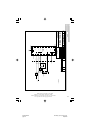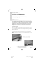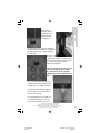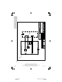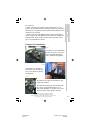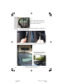
1
TM
Includes SG-237 Porta, SG-237 PCB and QMS-37
August 2001
SG-237 Manual
page 1
Thursday, July 26, 2001 16:13
Composite
S GC — The SSB People
SGC develops, manufactures, and sells high performance single sideband (SSB) communications equipment. Since
1971, the company has sold to the marine, military, aviation,
and industrial markets worldwide. Over these years, SGC has
earned an outstanding reputation for product reliability and for
after sales service.
The company keeps pace with equipment options, engineering developments, and design requirements. Its products
are the most competitive in the entire long distance communication market. SGC equipment is presently being used by the
United Nations for inter-communications in developing countries throughout the world.
Many competitive racing vessels, as well as fishing
boats, tugs, and commercial craft are equipped with SGC
equipment. In fact, an SGC radiotelephone provided the only
communications available on a past Polar expedition by the National Geographic Society.
SGC also supplies U.S. government
agencies, several foreign governmental agencies,
and major petroleum companies throughout Asia
and Latin America.
All SGC equipment is designed and
manufactured in the USA. SGC has qualified people ready to provide technical information, assistance in selecting equipment, and recommendations for any installation.
SGC welcomes your
call to discuss your SSB requirements.
Mailing: PO Box 3526, Bellevue, WA 98009
Shipping: 13737 SE 26th St., Bellevue, WA 98005
Toll-Free: 800-259-7331 • Phone 425-746-6310 • Fax: 425-746-6384
www.sgcworld.com • Email: [email protected]
2
SG-237 Manual
page 2
© 2001 SGC, Inc.
Thursday, July 26, 2001 16:13
Composite
Table of Contents
Specifications ……………………………………………4
1.0 Supplied Items ……………………………………… 5
2.0 Mechanical Design …………………………………. 5
2.1 Marine Mounting …………………………………… 5
2.2 Desert and High Temperature Installations ………… 6
2.3 Additional Weather Protection Installations ………. 6
3.0 Coupler Configuration……...……………………….. 6
3.1 Connections to SG-237………………………………6
3.2 Tuning Process …………………………………….. 7
3.3 Impedance Detector…………………………………. 7
3.4 VSWR Detector…………………………………….. 8
3.5 Phase Detector ……………………………………… 8
3.6 Central Processing Unit (CPU) …………………….. 8
3.7 Initialization…………………………………………. 9
3.8 Jumper Settings…………………………………….. 9
4.0 Tuning Process and Options ……………………….. 10
4.1 Program Description ……………………………….. 10
4.2 Tuning Paths ……………………………………….. 12
4.2.1 Antenna Too Short/Long………………………….. 12
4.2.3 Tuning Elements ………………………………….. 13
5.0 Coaxial Output Application………………………. 14
6.0 B.I.T.E. Status LED Descriptions………………….. 14
7.0 Optional Smartlock …………………………………. 15
7.1 Tune, Tune Lock, and Reset ……………………….. 15
7.2 Smartlock Notes ……………………………………. 15
8.0 Do-It-Yourself Light Bulb Dummy Load………….. 16
9.0 Five Golden Rules of HF Installation ………………. 18
10.0 Selected Antenna Configurations………………… 19
11.0 S t a n d a rd Warranty …………………………… 23
12.0 Component Location / Schematics……………….. 24
13.0 SG-237 Porta……………..……………………….. 32
14.0 SG-237 PCB……………………………………….. 35
15.0 QMS System……………………………………….. 38
16.0 Smartuner Application Comparison Chart………… 50
16.1 Smartuner Technical Comparison Chart………….. 51
Mailing: PO Box 3526, Bellevue, WA 98009
Shipping: 13737 SE 26th St., Bellevue, WA 98005
Toll-Free: 800-259-7331 • Phone 425-746-6310 • Fax: 425-746-6384
www.sgcworld.com • Email: [email protected]
SG-237 Manual
page 3
3
Thursday, July 26, 2001 16:13
Composite
Specifications - Subject to change without notice
HF Frequency Range: 1.8-60 MHz
Power Input Range:
3 to 100 watts (PEP)
Or 40 watts max. on CW
Or 100 watts for 4 second TX and 6 second RX
Number of channels:
Revolving memory bins:
Input Impedance Range:
VSWR: (Typical)
DC Input Requirement:
DC Operating Range:
Input Current: Average:
Random set time:
Recurrent set time:
Antenna Length:
Unlimited
168
45-55 ohms
Typically less than 1.4:1
+13.8 VDC (nominal)
+10 to 18.5 VDC
300 milliamps
Typical: less than 2 seconds
Typical: less than 10 milliseconds
Minimum length of 7 ft. - 3.5 to 60 MHz
Minimum length of 23 ft.– 1.8 to 60 MHz
Installation:
Any position
Operating Temperature: -35° to +70°C
Power Cable:
Shielded 4 conductor
RG-58 coax with PL-259 connector
Power Cable Length:
9 feet in length
Antenna types:
1. Whip
2. Backstay (marine, sail)
3. Dipole centerfed
4. Dipole with feedline
5. Loop (small) 2x2 multi turn
6. Loop (large) 10 ft. and up single turn
7. Longwire
8. Ladder feed
Size: SG-237
9”L x 7”W x 1.5”H (23cm x 18cm x 4cm)
SG-237 Porta 7.25”L x 6”W x 3”H(18cm x 15cm x 8cm)
SG-237 PCB
5.5”L x 6”W x 1”H (14cm x 15cm x 2cm)
Weight: SG-237
2 pounds (1 kg)
SG-237 Porta 4 pounds (2 kg)
SG-237 PCB
1.25 pounds (6 kg)
SG-237 Case
ABS plastic on anodized aluminum base
SG-237 Porta Case
Extruded Aluminum
Porta Ground System: Four radials of 12 feet each
4
PO Box
3526,
98009 coupler. Performance and
This manual is produced as aMailing:
guideline
for
theBellevue,
SG-237WA
antenna
13737
SE 26th any
St., Bellevue,
WA 98005
results may vary and SGCShipping:
does not
warrant
installation
or any result. This manual is
Toll-Free: 800-259-7331 • Phone 425-746-6310 • Fax: 425-746-6384
subject to change
without
notice.
© 2001 SGC, Inc.
www.sgcworld.com
• Email:
[email protected]
SG-237 Manual
page 4
Thursday, July 26, 2001 16:13
Composite
1.0 SG-237 Supplied Items
•
•
•
SG-237 Coupler
Manual
Cable RF/Control 9 foot long
2.0 Mechanical Design
The SG-237 is supplied in a weather proof case with mounting holes.
RF and DC power is supplied to the unit through the same cable. The
cable is a 9 foot 4 conductor (with coax for RF) cable with wires for
ground, power, optional SmartLock controls, and optional LED indicator.
The SG-237 antenna coupler’s weatherproof case is designed to withstand the environmental conditions encountered aboard ship when
mounted on the weatherdecks. The internal construction is designed to
withstand the shock and vibration of marine service. Corrosionresistant hardware and passive alloys are employed throughout. We
do not recommend opening the Smartuner case unless it is necessary.
For 99% of installations, the factory settings for jumpers will be correct. The coupler must be installed in an area not directly exposed to
the sunshine or rain. Should you have occasion to open the case, it
must be re-sealed under low humidity (below 35%) and care used to
ensure the gasket which seals the unit is placed properly to maintain
watertight integrity of the unit. Although the Smartuner is built very
solidly, it is good installation practice to provide additional protection
from the elements. SGC makes the following recommendations:
2.1 Marine Mounting
The Smartuner should be located inside the house or under the aft
lazaret on a sailboat. On power boats, the coupler may be mounted
outside, but an additional protective housing is recommended. The
preferred installation if vertical is with the RF terminals pointing upward. The antenna connects to the screws on the top. The SG-237
may be mounted in any position including inverted without any degradation of performance.
Mailing: PO Box 3526, Bellevue, WA 98009
Shipping: 13737 SE 26th St., Bellevue, WA 98005
Toll-Free: 800-259-7331 • Phone 425-746-6310 • Fax: 425-746-6384
www.sgcworld.com • Email: [email protected]
SG-237 Manual
page 5
5
Thursday, July 26, 2001 16:13
Composite
2.2 Desert and High Temperature Installations
The Smartuner may be used in very hot climates on a continuous basis
if some additional protection from direct sunlight is provided and if
coupler is installed in a protected area. Temperatures inside a vehicle
may exceed 212°F (100°C). It is desirable to keep the coupler in the
shade if possible.
2.3 Additional Weather Protection Installations
To protect the unit from direct exposure to sunlight and to prevent
heavy build up of ice, we recommend installing the Smartuner under
protective housing. If you are mounting it on a tower in a hot or cold
climate, a plastic wastebasket (such as those made by Rubbermaid™)
makes an excellent weather cover and costs only a few dollars.
Long wire antenna
Smartuner mounted inside a plastic waste
basket to protect it from extreme heat and
heavy icing. This type of enclosure is widely
available in all countries.
3.0 Coupler Configuration
Schematic Q30102700, sheet 4, page 29 is the schematic diagram of
the two basic coupler net-works. Note that the L network as viewed
from the generator, may be configured as either “C in” or “C out,”
whichever is required by the load. In either case, the end of the network containing the shunt C element will be the higher impedance end
of the network.
3.1 Connections to SG-237
Drawing Q40105418, page 31 is the diagram of the antenna coupler
connections. RF input and ground is applied to the PL259 connector on
the end of the cable, +13.6 VDC is connected to the red wire - ground
to the black wire, and an appropriate antenna and RF ground system
are connected to the Antenna stud and the RF ground stud respectively.
The TND line (white with black trace wire) can be connected to the
Mailing: PO Box 3526, Bellevue, WA 98009
Shipping: 13737 SE 26th St., Bellevue, WA 98005
Toll-Free: 800-259-7331 • Phone 425-746-6310 • Fax: 425-746-6384
www.sgcworld.com • Email: [email protected]
6
SG-237 Manual
page 6
© 2001 SGC, Inc.
Thursday, July 26, 2001 16:13
Composite
transceiver or the SmartLock. This line cannot be connected to both
units simultaneously.
3.2 Tuning Process
An array of detector devices in the SG-237 monitor the antenna system impedance, reactance signal, and the VSWR load when RF power
is applied to the unit. The coupler also monitors forward power, since
the control computer requires an indication of both forward and reflected power in order to allow tuning to proceed. The computer uses
the forward power detector as a check to ensure that the measurements
made are applied RF and are not spurious levels from the data conversion system. The SG-237 will proceed to tune only when enough forward power is present to confirm this check. After RF is applied to the
detector system, it then passes through the coupler tuning array. The
coupler tuning array consists of seven capacitors in shunt on the input
arm of the network, eight inductors in the series arm, and four more
capacitors in shunt on the output arm, all arranged in binary increments. Relays are provided in conjunction with each lumped constant
and allow removal or entry as desired. A network having 128 values
on input shunt C, 16 values of output shunt C, and up to 256 values of
series L is possible with the manipulation of these 19 relays.
3.3 Impedance Detector
RF transformers T1 and T3 drive the impedance bridge that is balanced at 50 ohms. T3 samples the line current and thus D7 out-puts a
negative DC level proportional to line current. A tertiary winding on
transformer T1 provides a line voltage sample to D2 that provides a
positive voltage proportional to line voltage. R18 and R11 act as a
summing network for the current and voltage signals, with ratios chosen, such that at 50 ohms, the summed signals result in a balanced or
zero voltage condition. If the line impedance goes to high, the signal
from the voltage sensor will be relatively higher than the current sensor, which will result in a net positive output voltage from the summing network. Similarly, a low line impedance will result in more output from the current sensor, resulting in a net negative output voltage
from the summing network. The summing network output is shifted to
a 0 to 5v range, then fed to the processor's A to D converter port, and
used within the micro-controller.
Mailing: PO Box 3526, Bellevue, WA 98009
Shipping: 13737 SE 26th St., Bellevue, WA 98005
Toll-Free: 800-259-7331 • Phone 425-746-6310 • Fax: 425-746-6384
www.sgcworld.com • Email: [email protected]
SG-237 Manual
page 7
7
Thursday, July 26, 2001 16:13
Composite
3.4 VSWR Detector
A directional coupler is made up of a current transformer T2 and a
voltage transformer T1, in conjunction with termination resistors R35,
R36 and R33, R34. The coupler is inserted in the 50-ohm transmission
line between the input connector, ST2 RF - ST3 GND, and the tuning
network. The forward power is measured across termination R33, R34
and reflected power is measured across termination R35, R36. Diode
D1 generates a positive DC voltage proportional to forward power and
D3 generates a positive DC voltage proportional to reflected power.
The forward DC output is fed to a voltage divider consisting of R19
and R14. These voltages are input to the RF power detector and to an
A to D converter port of the processor. The reflected DC output passes
through a voltage divider consisting of R29 and R16, and then it also
goes to an A to D converter port of the processor.
3.5 Phase Detector
A phase detector is formed by T3, A1, and their associated components. This detector indicates the state of any reactance associated with
the antenna coupler as noted from the generator. A line current sample
is compared in phase with a voltage sample in a double balanced
mixer. Output polarity varies negative or positive depending on the
reactance of the antenna. The output of phase detector A1 is shifted to
a 0 to 5v range, then fed to processor’s A to D converter port and used
within micro controller.
3.6 Central Processing Unit (CPU)
A tune-up algorithm, which is contained in the memory of the microprocessor, implements the antenna matching. It is designed around the
MC68HC711E9 CPU that features a versatile instruction set, RAM,
and EEPROM (memory which is saved after the coupler is turned off).
The antenna coupler relays are controlled by latches U6, U7, & U8
which receive serial data input directly from the CPU. During operation, data is transferred into the CPU from the A to D ports and Input
Capture port (measures RF frequency). Basically, the program monitors the status of the input sensors and—starting from a preset condition—uses a built-in algorithm to achieve a tuned condition. When the
tuning algorithm is complete, the CPU saves the settings in its
EEPROM, which is addressed by the applied RF frequency. This nonMailing: PO Box 3526, Bellevue, WA 98009
Shipping: 13737 SE 26th St., Bellevue, WA 98005
Toll-Free: 800-259-7331 • Phone 425-746-6310 • Fax: 425-746-6384
www.sgcworld.com • Email: [email protected]
8
SG-237 Manual
page 8
© 2001 SGC, Inc.
Thursday, July 26, 2001 16:13
Composite
volatile memory table is the basis of the exclusive learning feature of
the SG-237. After it has stored and latched the network status, the
CPU waits for RF to cease transmitting and returns to the Stop mode.
When RF is re-transmitted, the first step in the tuning algorithm is to
measure the frequency of the signal passing through the coupler. From
the frequency data, the computer then searches its EEPROM for previously stored data. If data is found, it is tested for validity, and the required “end of tune” conditions will be sensed by the RF sensors.
Then the data will be latched in place, and the CPU will again wait for
RF to cease transmitting and turn to the Stop mode. This process takes
about 10 milliseconds, which is the same length of time that is required to close the network relays.
3.7 Initialization
The microcomputer is usually in the Stop mode and requires an interrupt signal (XIRQ) to start program implementation. The XIRQ is obtained from the RF detector circuitry. This line, going low, will wake
the CPU from the Stop mode.
3.8 Jumper settings
The SG-237 may be bypassed for broad band (un-tuned antenna) scanning listening in receive mode. All you need to do is press the reset
button of the SmartLock (if installed) or turn power to the coupler off
and on. When the coupler comes back on, the tuning elements remain
out of the circuit until the Smartuner is activated by a transmitted signal. If broad band operation is required during receive for scan operation, jumper JP1 may be set to the Yes position. This will drop the tuning elements out of the circuit on receive only. Jumper JP1 is located
adjacent to MCU (U5) along the edge of the printed circuit board. Setting JP1 to the Yes position is recommended if you are using a radio
for split band communications, for scanning selective calling protocols, or for Automatic Link Establishment (ALE). The default is: Tuning Out In Rcv: [NO].
Jumper JP3 bypasses the coupler's memories. This means that each
time the coupler is used on a different frequency, it will re-tune rather
than use previously stored information. The default is: Tune From
Memory: [YES].
Mailing: PO Box 3526, Bellevue, WA 98009
Shipping: 13737 SE 26th St., Bellevue, WA 98005
Toll-Free: 800-259-7331 • Phone 425-746-6310 • Fax: 425-746-6384
www.sgcworld.com • Email: [email protected]
SG-237 Manual
page 9
9
Thursday, July 26, 2001 16:13
Composite
4.0 Tuning Process and Options
MicroTune™ Software
Copyright 1991-2001
The SG-237 MicroTune™ Software is unique software which allows precise tuning of the digitally controlled π and L network to tune a wide variety of antennas. The versatile MicroTune™ software offers its user these
special functions:
1. The coupler is activated whenever forward power is present.
2. In addition to sampling VSWR to determine if the coupler should retune, frequency comparison is employed. This causes the coupler to tune
when ever the transmit frequency changes independent of the VSWR reading.
3. Extensive tuning paths are used to test different antenna situations. The
initial tuning of a new frequency (or switched antenna) may require up to
two seconds. Any further tuning is accomplished in a matter of milliseconds if jumper JP3 (Tune From Memory) is in its default position.
4. Facilities and algorithms are used which enable accurate tuning at the
low end of the frequency band—even on shorter antennas than previously
possible.
5. The BITE (Built-In-Test-Equipment) Indicator Tune LED includes a
safety feature that alerts the operator to a mismatched condition, with blinking indicators, when proper tuning conditions have not been met. In this
situation, the software will “time out” within 20 seconds unless a new frequency is sensed, which will cause an immediate time out, and the coupler
will attempt to match the new frequency. The microprocessor of the coupler
“wakes up” every time the coupler has forward power. However, re-tuning
takes place only if the frequency has changed or the VSWR exceeds 2:1.
4.1 Program Description
When DC power is applied, the computer initializes the processor registers
in accordance with the hardware. All tuning elements are then removed and
the 'tune' indicators are turned off. At this time the computer reverts to a
"sleep" mode awaiting RF power.
Detecting forward power. Once forward power is detected and the optional
SmartLock is switched to Normal, the current coupler settings are sent to
the relays. Next, the VSWR is checked and the frequency measured. If the
10
SG-237 Manual
page 10
Mailing: PO Box 3526, Bellevue, WA 98009
Shipping: 13737 SE 26th St., Bellevue, WA 98005
Toll-Free: 800-259-7331 • Phone 425-746-6310 • Fax: 425-746-6384
www.sgcworld.com • Email: [email protected]
© 2001 SGC, Inc.
Thursday, July 26, 2001 16:13
Composite
-
VSWR is greater than 2:1 or a difference in frequency is detected, the
program branches to the re-tune program. If it is determined that the
VSWR is less than 2:1 and the frequency has not changed, the computer returns to the Stop mode. Re-tuning. Once it is determined that
re-tuning is necessary, a test is made to see if JP3 is set to tune from
memory. If the result is re-tuning from memory, settings are recalled
from the EEPROM based on the frequency measured. The recalled
data is then tested for validity. If the data proves invalid, it is bypassed
and re-tuning is performed. If the data recalled proves valid, the data is
sent to the relays and the VSWR is checked. If the VSWR is less than
2:1, the program branches to the “OK Tuned” section of the program.
If the VSWR is found to be greater than 2:1, the program branches to
the “re-tune” program.
Selecting tuning path. Several tests are made to determine which tuning algorithm or path should be used to tune the coupler. These tests
are based on frequency, antenna input impedance, antenna phase, and
VSWR. Numerous subroutines are executed repeatedly, depending on
the status of the criteria mentioned above, in order to achieve proper
tuning.
k-
er
g
s
d
l
Signaling “no-tune.” Should the initial primary tuning sequence prove
unsuccessful, secondary algorithms are attempted until all possible
routines have been exhausted. If, after the secondary attempts, the coupler still cannot achieve a proper VSWR, the program branches to a
“no-tune” program. Here, the LED's and remote tune indicator will
blink on and off for about 15 seconds to tell the user a proper VSWR
could not be found. After the indicators stop blinking, the program
waits for forward power to cease (if it has not ceased already) and returns to stop mode. At this point the user should try several other frequencies. If the “no-tune” condition persists, check the installation of
the antenna, coupler, radio, and ground system for possible problems.
Signaling “OK tune.” If the coupler achieves a good VSWR during the
tuning sequence, the program branches to the “OK Tune” section of
the code. Here, the tune indicators are engaged. A test is then made to
check if JP3 is set to tune from memory. If so, the frequency is measured and the tuning elements used are saved in memory coupled with a
verification code. Once saved, a test is made on JP1 to check if the
Mailing: PO Box 3526, Bellevue, WA 98009
Shipping: 13737 SE 26th St., Bellevue, WA 98005
Toll-Free: 800-259-7331 • Phone 425-746-6310 • Fax: 425-746-6384
www.sgcworld.com • Email: [email protected]
SG-237 Manual
page 11
11
Thursday, July 26, 2001 16:13
Composite
duplex mode has been selected. If so, the transmit tuning elements remain in circuit until the receive mode is verified. At this time, all tuning elements are removed. The frequency is then saved for future comparison and the CPU reverts back to the STOP mode.
4.2 Tuning Paths
As mentioned previously, various tests are executed to determine the
most logical tuning sequence to be performed. Dependent on the test
results, additional tests and appropriate sub-routines are executed
throughout the tuning process. Following are examples of the activity
that occurs when the coupler must be matched to a frequency that requires a slightly longer or shorter antenna:
4.2.1 Antenna Too Short
Once coupler has verified RF power, tuning sequence proceeds as follows:
1. Series inductance is added until the phase is deemed as being inductive. At this point it is normal for the input impedance to be low.
2. Input capacitance is added until the antenna is no longer inductive.
3. The program will continue to increment the series inductance in .125
µH steps—each time normalizing the input impedance with input capacitance until a low VSWR is measured of less than 2:1. This process
will continue until the VSWR has climbed back to higher than 2:1 or
the impedance has become high.
4. The settings that gave the lowest VSWR have been kept in memory
and are now recalled to verify it is a low VSWR
5. At this point the tune indicators are engaged. The current relay data
is saved if JP3 is set to tune from memory; if JP1 is set to tune elements out during receive position, the program waits until forward
power is no longer present, then removes all tuning elements. The frequency is saved for future frequency comparison, and the computer
reverts to Stop mode.
4.2.2 Antenna Too Long
Once the coupler has verified RF power, the tuning sequence proceeds
as follows:
1. Output capacitance is added until the phase switches to capacitive.
2. At this point, series inductance is added until the antenna is no
12
SG-237 Manual
page 12
Mailing: PO Box 3526, Bellevue, WA 98009
Shipping: 13737 SE 26th St., Bellevue, WA 98005
Toll-Free: 800-259-7331 • Phone 425-746-6310 • Fax: 425-746-6384
www.sgcworld.com • Email: [email protected]
© 2001 SGC, Inc.
Thursday, July 26, 2001 16:13
Composite
longer capacitive.
3. Fine tuning is performed by trying a small amount of input capacitance (this may or may not be required).
4. At this point, the program acts the same as step 5 in section 4.2.1
The preceding gives a simplified program flow on only two possible
antenna conditions. Much more complex tuning is normally the case.
Further detailed description is beyond the scope of this manual.
4.2.3 JP1—Tuning Elements Out During Receive
(Factory Default Setting: No)
YES - In this position the software will retain data required in transmit
to match the coupler while removing all tuning elements when no forward power is detected.
NO - In this position, coupler will retain the required tuning data and
will change nothing whether in receive or transmit. If typical operation
is out of band duplex, Yes would be most likely to give better performance. If in band, operation is typical and duplex or simplex is the
predominant mode of operation, then No is usually the better choice.
4.2.4 JP3—Tune From Memory
(Factory Default Setting: Yes)
YES - In this position the coupler will recall data previously saved and
try this data before attempting to re-tune. If the data is valid and the
VSWR is less than 2:1 the tune is completed. In this position the coupler will save any new data in its memory for any frequency. A new
frequency must first be learned, while in this mode, before it can be
recalled.
NO - In this position, the coupler will not use previously saved tuning
data. Each time a different frequency is selected, the coupler will proceed through a complete tuning sequence. Clearly, the advantage of
Yes is speed. The coupler will seem to be matched instantly when in
this position, if the frequency being used has previously been saved in
EEPROM. Disadvantages include a difference in frequency too small
for the computer to detect. This would result in recall of valid data that
may not necessarily present the best match. We suggest starting with
JP3 in the Yes position. If operation is as expected, don't change it.
Mailing: PO Box 3526, Bellevue, WA 98009
Shipping: 13737 SE 26th St., Bellevue, WA 98005
Toll-Free: 800-259-7331 • Phone 425-746-6310 • Fax: 425-746-6384
www.sgcworld.com • Email: [email protected]
SG-237 Manual
page 13
13
Thursday, July 26, 2001 16:13
Composite
5.0 Coaxial Output Application
SGC always recommends placing the antenna coupler as close as possible to the base of the antenna - regardless of whether it is an SGC
coupler or another brand. All SGC couplers can be operated with a coaxial cable output connection; but this is not our recommendation. Antenna “tuners” which use coaxial cable connections are actually trimmer tuners and have a limited adjustment range (25 to 800 ohms). This
impedance limitation prevents high voltages and current which may
cause flashing or burning of the coaxial cable. Keep in mind that this
limitation is created by the coaxial cable - not the coupler. Trimmer
tuners are less expensive than antenna couplers and much more common. However, because of their impedance range limitation, they cannot tune whip or end fed wire antennas. On the other hand, SGC antenna couplers are not limited in their impedance ranges and will tune
all types of antennas, including end fed wire and whips.
6.0 B.I.T.E.* Status LED Descriptions
*Built In Test Equipment
TND
This LED will light when the tuner has found an acceptable match. It will remain lit until conditions
have changed which will cause the tuner to find a different match. (i.e. A new transmit frequency has
been detected, or tuner has been reset.)
L'Z'
This LED shows the status of the antenna impedance. When lit, the impedance is 50 ohms or less. When
off, the impedance is greater than 50 ohms.
2:1
This LED will light when the VSWR is greater than 2:1. It will extinguish when VSWR is less than 2:1.
PHZ
This LED indicates the status of the antenna reactance. When lit, reactance is inductive. When off, reactance is capacitive.
FWD
This LED indicates the presence or lack of RF power from the radio. When transmitting, the LED will
light to indicate RF is being detected. In receive, the LED should be extinguished.
OTHER
All LEDs will blink on and off at a rate of 2Hz to indicate the tuner was not able to find a valid match.
Note that these status LEDs are usually used to aid a technician in diagnosing the status of the antenna
system and should not be thought of as laboratory instruments.
As the Smartuner tunes, the BITE status will be continually updated from the CPU.
14
SG-237 Manual
page 14
Mailing: PO Box 3526, Bellevue, WA 98009
Shipping: 13737 SE 26th St., Bellevue, WA 98005
Toll-Free: 800-259-7331 • Phone 425-746-6310 • Fax: 425-746-6384
www.sgcworld.com • Email: [email protected]
© 2001 SGC, Inc.
Thursday, July 26, 2001 16:13
Composite
7.0 Optional Smartlock
The SmartLock allows the operator to have additional control over the
SG-237. It is not required for normal operation of the coupler.
7.1 Tune, Tune Lock/Reset
Tuned (green LED)
Turns on when the coupler has successfully tuned.
Normal/Tune Lock
Toggle switch which allows user to prevent coupler re-tuning by
switching to the Tune Lock position. When in the Tune Lock position,
the red LED blinks to notify the user that the coupler is locked on the
current setting.
Reset
Pushing the red reset button allows the coupler to be reset, if the toggle switch is in the normal position. This is preferred over turning the
input power off and on.
7.2 SmartLock Notes
The Tune Lock function is in most cases unneeded. Inadvertent retuning is a rare occurrence. Re-tuning may occur when the environment or antenna system has changed. In this case, re-tuning is within
normal operation of the coupler.
+13.6VSW
RED
R3
330
+1 3 .6 VSW
GREEN
TUNED FROM COUPLER
WHITE
NO TUNE /
RESET FROM COUPLER
BLA CK
Q1
2 N2 2 2 2
RESET
R1
150
GROUND
1 3 6 4
D1
1 N7 5 7
Red
NORMA L
2
C2
0 .1 µ F
CA1
SW1
DPDT
SW2
PUSH But t on
DS2
Red LED
DS1
Gr een LED
Gr een
Whi t e
Bl ack
5
R2
330
C1
C3
0 .1 µ F 0 .1 µ F
Mailing: PO Box 3526, Bellevue, WA 98009
Shipping: 13737 SE 26th St., Bellevue, WA 98005
Toll-Free: 800-259-7331 • Phone 425-746-6310 • Fax: 425-746-6384
www.sgcworld.com • Email: [email protected]
SG-237 Manual
page 15
15
Thursday, July 26, 2001 16:13
Composite
8.0 Do-It-Yourself Light-Bulb Dummy Load
Any time that a transmitter is used, it must be outputting into a load. A
load is anything that the output power can be pumped into. If the transmitter is operated without any sort of load connected, the final amplifier stage could become severely damaged. The problem is that you
should never test a transmitter on the air for the first time, if you are
unsure about how to operate it, and if you are unsure whether it is
working properly. You could create harmful interference to other stations.
To test transmitters without actually operating into an antenna, dummy
loads were created. A dummy load is a load that will dissipate the energy from the transmitter instead of emanating it into the ionosphere.
Nearly all commercial dummy loads are large oil-filled cans. These
dummy loads change the transmitted energy into heat, which is absorbed by the oil. Because different transmitters output different
amounts of power, different sizes of dummy loads must be used.
Dummy loads for typical amateur powers (<500 watts) are relatively
inexpensive and are readily available.
Unfortunately, when you use a can-type dummy load, you can't see
"what's happening" with your transmitter. In this case, you can use a
light-bulb dummy load to test your transmitter. Here, the light bulb is
directly connected to the output of the transmitter and it dissipates the
RF energy as light. The light bulb dummy load is more useful than the
oil-can type because you can guess how much power is being output,
you can see the voice modulate the SSB (the light will flicker with
your voice peaks), and you can tune the transmitter for maximum output (if the transmitter is an older model that requires tuning).
Before building or using the light-bulb dummy load, remember that
these models typically don't dissipate the transmitter's output as well as
an oil-can dummy load. The result is that RF will "leak" out; we have
heard a few stories of amateurs who were heard around town while operating their transmitters into a light-bulb dummy load. If you use this
system, make sure that you test the equipment on a clear, harmless frequency. (NEVER test with the transmitter set on an emergency frequency.)
16
SG-237 Manual
page 16
Mailing: PO Box 3526, Bellevue, WA 98009
Shipping: 13737 SE 26th St., Bellevue, WA 98005
Toll-Free: 800-259-7331 • Phone 425-746-6310 • Fax: 425-746-6384
www.sgcworld.com • Email: [email protected]
© 2001 SGC, Inc.
Thursday, July 26, 2001 16:13
Composite
SGC recommends that you build the light-bulb dummy load with the
following parts (although we have made one with an old light fixture
and a makeshift version with just alligator clip leads and a light bulb):
* AC socket to cable with a PL-259 connector (for transceiver)
* AC socket to cable with alligator clips (needed with coupler)
* Light bulb to AC adapter
* 75 to 125 watt light bulb, 120 to 220 VAC
* 100 watt radio transceiver
* Any SGC Smartuner or equivalent
RADIO TEST PROCEDURE
1. Connect the transceiver light bulb load to the radio RF in/out jack.
2. Turn on the radio and set the CW mode.
3. Key the PTT switch on the microphone and look at the light bulb. If
the light bulb load is connected and the radio is transmitting, the light
should turn on.
4. Set the radio to SSB mode.
5. Key the PTT switch on the microphone and talk into the microphone. Notice that the light turns on when you talk.
COUPLER TEST PROCEDURE
1. Connect the coupler to the radio.
2. Connect coupler
light bulb load to
Smartuner coupler
antenna output.
3. Turn on radio and
Smartuner coupler.
4. Set the radio to the
CW mode.
5. Key the PTT
switch on the microphone and look at the
light bulb. The light
should turn on if the
coupler has completed its' tuning cycle and if the radio is
transmitting.
RF GND
RF IN-OUT
Radio
RF GND
Antenna Jack
RF IN-OUT
Antenna Coupler
GND
Radio
Mailing: PO Box 3526, Bellevue, WA 98009
Shipping: 13737 SE 26th St., Bellevue, WA 98005
Toll-Free: 800-259-7331 • Phone 425-746-6310 • Fax: 425-746-6384
www.sgcworld.com • Email: [email protected]
SG-237 Manual
page 17
17
Thursday, July 26, 2001 16:13
Composite
6. For further testing, follow steps 4 & 5 of the radio test procedure
on page 17. Note: The light bulb might not turn on immediately if
coupler has not yet been tuned for the frequency of the transmitter.
The output power (light-bulb brightness) is greatest when coupler is
properly tuned.
This test will ensure that the radio and coupler are working properly.
9.0 Five Golden Rules of HF Installation
These rules apply to all types of stations, including base, mobile, airborne and marine. They are very important for planning and installing your HF system, if you want to achieve good communications.
1. Install transceiver as close to operation site and power supply system as possible (whether an external power supply or battery system).
2. The antenna must be installed in an open space and as far as possible from your operating point. Ex: on a sailboat, use the backstay as
the antenna, since it is the farthest point away from the rest of the
vessel.
3. The antenna coupler must be installed at the base of the antenna.
4. Always create your own ground with radial wire or copper straps.
They will guarantee a solid and proper ground system.
5. All cables - power supply, control or coaxial - must always be as
short as possible and/or necessary. Any excess cable should be shortened to the proper length - never coiled.
Following these rules will minimize marginal installations and problem sources such as RF feedback in the radio, power supply or cables and "hot" or RF burning microphones. If all 5 above points are
followed during the design and installation of your HF system, the
operator can expect top performance. Further information regarding
applications, installation and operation can be downloaded from our
website www.sgcworld.com. These publications include:
• HF User's Guide
• Go Mobile at 500 Watts
• Stealth Antennas
• Smartuner Antenna Coupler Manuals
This manual is produced as a guideline for the SG-237 antenna coupler. Performance and results may vary and SGC does not warrant any installation or any result. This manual is subject to change without notice.
18
SG-237 Manual
page 18
Mailing: PO Box 3526, Bellevue, WA 98009
Shipping: 13737 SE 26th St., Bellevue, WA 98005
Toll-Free: 800-259-7331 • Phone 425-746-6310 • Fax: 425-746-6384
www.sgcworld.com • Email: [email protected]
© 2001 SGC, Inc.
Thursday, July 26, 2001 16:13
Composite
10.0 Selected Antenna Configurations
2.0 M whip
Ground
coupler
securely
to truck
Feed through insulator
18" PVC
pipe
standoffs
Recreational Vehicle
Antenna Installation
Antenna wire
Metal roof
of vehicle
Coupler
Transceiver
Coupler mounted
inside coach
Use a separate ground strap or wire for the body
a n d t h e c h a s s i s t o t h e g r o u n d o f t h e c o u p l e r.
Vehicle Installation
10.1 Automobiles: RVs or trailers provide an excellent base to install effective low cost antennas, and end feed or loop antennas can
be used.
Radiation
Porcelain
isolators
with tie rope
Coupler
Ground
bolt
terminal
50 ohm
coax from
transmitter
Antenna
terminal
Base Quadra
Loop Horizontal
10.3 Flagpole: If a flagpole
is made of PVC pipe, it is
easy to tape a large gauge
wire to the inside of the pipe
and use a good counterpoise.
Typical flagpoles are 25 to 35
feet in height and offer excellent performance on all
bands.
10.2 Buildings: The horizontal quad
loop is a groundless antenna for high
angle radiation and is ideal for HF
communications up to 500 miles in the
frequency range of 2 to 10 MHz. This
configuration provides optimum nearright angle reflection to the ionosphere
for short-range communications.
Coupler
At least three ground radials
longer than the flag pole
Mailing: PO Box 3526, Bellevue, WA 98009
Shipping: 13737 SE 26th St., Bellevue, WA 98005
Toll-Free: 800-259-7331 • Phone 425-746-6310 • Fax: 425-746-6384
www.sgcworld.com • Email: [email protected]
SG-237 Manual
page 19
19
Thursday, July 26, 2001 16:13
Composite
10.4 Roofs/Walls: E. Under a
roof overhang, all kinds of wire
antennas may be installed.
F. All types of antennas may be
hidden inside the roof of a building that uses non-metallic roofing materials. Loop antennas are
good for this type of installation.
G. A downspout, rain gutter antenna works well if the piping
and gutter are aluminum.
Coupler
F
Coupler
E
G
Coupler
Rotary Aircraft
10.5 Helicopters: The
Smartuner will also
match well the more
common wire antenna
from fuselage to vertical
stabilizer (and continuing to a wing tip, if desired) and a long wire
antenna under the tail
rotor of helicopters.
Coupler
Isolator
Wire antenna
Strut to space out
antenna with plastic
tubing or fiberglass
rod
10.6 Airplanes: When installed in an aircraft, the
Smartuner will operate well
with a shunt-fed antenna. This
is generally a 13-foot piece of
metal that mounts on the fuselage and is grounded to the
aircraft at one end.
20
SG-237 Manual
page 20
Fixed Wing Aircraft
Wire goes to
the coupler
Isolator
Wire antenna
Ground
Aviation
control
head
Coupler
Wire antenna
Isolator
Radio
Mailing: PO Box 3526, Bellevue, WA 98009
Shipping: 13737 SE 26th St., Bellevue, WA 98005
Toll-Free: 800-259-7331 • Phone 425-746-6310 • Fax: 425-746-6384
www.sgcworld.com • Email: [email protected]
© 2001 SGC, Inc.
Thursday, July 26, 2001 16:13
Composite
10.7 Insulated Backstay:
The coupler must be placed
as close as possible to the
base of the backstay antenna.
Connect the RF ground terminal to all of the metal parts
or structures of the boat.
Porcelain
isolator
Radiation
75 feet
Vessel
insulated
Backstay
Coupler
Porcelain
isolator
Ground
connection
Radiation
75 feet
Vessel
Groundless
Loop
Coupler
Lower mast connection
to coupler RF ground
Porcelain
isolator
10.8 Triangular Loop Antenna: This
antenna for sailboats is designed to operate in a groundless environment and still
provide high performance. This type of
installation will require only one insulator point on the bottom back stay and an
electrical connection on top of the mast
and the stay. The grounded side of the
coupler should be connected to the bottom of the mast.
10.9 Delta Loop Antennas: These
are ideally suited to long range
communications due to their low
angle. This configuration is best for
communications ranging from 500
to 5000 miles in the HF frequency
range of 4 to 22 MHz. Noise rejection is excellent. Because the antenna system is not connected to a
ground, noise rejection is enhanced.
Radiation
Coupler
Base Delta Loop
Mailing: PO Box 3526, Bellevue, WA 98009
Shipping: 13737 SE 26th St., Bellevue, WA 98005
Toll-Free: 800-259-7331 • Phone 425-746-6310 • Fax: 425-746-6384
www.sgcworld.com • Email: [email protected]
SG-237 Manual
page 21
21
Thursday, July 26, 2001 16:13
Composite
Feed through insulator
10.10 Long Wire Antenna:
These on a fishing vessel perform well and are very efficient
because antenna lengths of 50
feet or more can be installed
without any difficulties. If vessel
is not of a metal structure 3 radial wires as long as possible can
be connected to the coupler and
spread on the lower bottom part
of the vessel.
Coupler
Suitable stay cable
Ground to
steel bulkhead
or overhead
Motor Vessel Installation
up to 300 feet
up to 200 feet
Balanced Line Feeders
300-600 Ohms
GND
10.11 Ladder feed Antenna:
These may be used if necessary,
however, installation of the
coupler directly at the antenna
is preferred for higher efficiency.
Hot
1 meter
3 meters
E66 insulators
(x8)
GND
Hot
Coupler
RF cable Control cable
Base Ladder Installation
7 to 25 meters
Coupler
3 meters
10.12 “V” Antennas: Both “V”
and inverted “V” antennas are
convenient for limited space
installations and increase of
directivity.
Control cable
RF Cable
Base Dipole Installation
22
SG-237 Manual
page 22
Mailing: PO Box 3526, Bellevue, WA 98009
Shipping: 13737 SE 26th St., Bellevue, WA 98005
Toll-Free: 800-259-7331 • Phone 425-746-6310 • Fax: 425-746-6384
www.sgcworld.com • Email: [email protected]
© 2001 SGC, Inc.
Thursday, July 26, 2001 16:13
Composite
11.0 SGC Limited Product Warranty
And SOFTWARE LICENSE
SG-237 & SG-237 Porta - 90 Days Parts & Labor
SG-237 PCB - 30 Days Parts & Labor
This manual is produced as a guideline for the SG-237 antenna coupler. Performance and results may vary and SGC does not warrant any installation or any
result. This manual is subject to change without notice. You have purchased an
SGC equipment product together with a license to use the software installed in
that product. Please return the warranty registration card that accompanies this
product, so that we can assure that you receive proper warranty service and important notices that may affect the product. This SGC product is warranted to be
free from defects in workmanship and material for a period of days from the
original buyer’s date of purchase. In the event of a defect, malfunction or failure
of which SGC receives notice during that time period, SGC, at its’ option, will
repair or replace the product free of charge to the buyer. The buyer must contact
SGC for a Return Material Authorization Number (RMA) and deliver the product back to SGC with this RMA number and written proof as to date of purchase. SGC will ship a new or repaired product to the buyer, reserving discretionary right to return a newer model that offers at least equal performance. The
foregoing warranty extends to the original buyer and does not include (a)
buyer’s cost to return the product to SGC, (b) buyer’s costs to remove or reinstall the product for warranty work, or (c) added costs of special expedited shipment that may be requested by buyer. Except for the limited warranty stated
above, and to the full extent permitted by law, SGC disclaims any other express
or implied warranties and liability for any incidental, consequential, special or
exemplary damages in connection with its product, even if SGC or its agents are
advised that such damages are foreseeable. (Note: Some states do not allow the
exclusion or limitation of incidental or consequential damages, so the above
exclusion may not apply to you). There is no warranty with respect to (a) the
product’s transmission range or geographical coverage which can vary by location (b) non-performance caused by using an inadequate or improper antenna or
grounding system or (c) routine maintenance, periodic adjustment and performance testing of the product or system. SGC customarily charges a flat fee for
repairs performed outside of the warranty coverage. To inquire about such
charges, please contact SGC. SGC warrants that the SOFTWARE included in
this product will perform in substantial accordance with the documentation.
SGC grants to the original end user of its product a non-exclusive worldwide
license to operate the software installed therein. This license shall be transferred
to any person or entity that subsequently acquires lawful ownership of the product. This license shall be limited to using the software for contemplated operation of SGC’s product. This license does not permit any end user to (a) modify
or adapt SGC’s software or to merge it into another program (b) reverse engineer, disassemble, or otherwise attempt to discover SGC’s software source code
or (c) sub license or otherwise transfer SGC’s software for any use other than
operating the product originally purchased from SGC.
Mailing: PO Box 3526, Bellevue, WA 98009
Shipping: 13737 SE 26th St., Bellevue, WA 98005
Toll-Free: 800-259-7331 • Phone 425-746-6310 • Fax: 425-746-6384
www.sgcworld.com • Email: [email protected]
SG-237 Manual
page 23
23
Thursday, July 26, 2001 16:13
Composite
12.0 Component Location / Schematics
24
SG-237 Manual
page 24
Mailing: PO Box 3526, Bellevue, WA 98009
Shipping: 13737 SE 26th St., Bellevue, WA 98005
Toll-Free: 800-259-7331 • Phone 425-746-6310 • Fax: 425-746-6384
www.sgcworld.com • Email: [email protected]
© 2001 SGC, Inc.
Thursday, July 26, 2001 16:13
Composite
Mailing: PO Box 3526, Bellevue, WA 98009
Shipping: 13737 SE 26th St., Bellevue, WA 98005
Toll-Free: 800-259-7331 • Phone 425-746-6310 • Fax: 425-746-6384
www.sgcworld.com • Email: [email protected]
SG-237 Manual
page 25
25
Thursday, July 26, 2001 16:13
Composite
26
SG-237 Manual
page 26
Mailing: PO Box 3526, Bellevue, WA 98009
Shipping: 13737 SE 26th St., Bellevue, WA 98005
Toll-Free: 800-259-7331 • Phone 425-746-6310 • Fax: 425-746-6384
www.sgcworld.com • Email: [email protected]
© 2001 SGC, Inc.
Thursday, July 26, 2001 16:13
Composite
B
1W
100
1W
R35
A
R1
1.5K
R32
33k
T1
1W
T2
C
33k
1W
R33
100
12p
C1
R2
RF PATH
ST2
RF
ST3
GND
R27
33
1W
D5
1W
R28
33
10
R31
2
5
6
7
A1
100
8
1
C12
.01u
R29
10k
R14
3
4
3
10k
10k
R12
36k
4
C11
.01u
R15
R16
10k
10k
1
C
L
P
R
R10
CLK
D
U2A
74F74
R19
VCC
2
2
C16
.1u
74HCT14A
U11A
R26
D7
10k
R11
.01u
1k
R30
R20
1.5k
1
D6
27k
R18
5.6k
R21
R3
1.5k
C13
D8
D9
D3
D1
C6
R36
100
1W
.001u
15p
C8
T3
C7
.001u
D2
.1
R34
100
1W
C9
.01
C14
.1
C10
14
D4
10k
Q
Q
C5
.001u
7
1k
R25
9
10
1
0
0
0
1
3
C
L
P
R
REV
CLK
D
100k
R4
10k
11
12
C3
.001u
C4
.001u
C2
.001u
R17
R13
10k
6
5
U2B
74F74
8
9
8
4.7k
R24
LM324
U1C
Q1
2N2222
RF-DET1
Q
Q
7
2
1
R8
Date:
A
Size
Title
100k
7
LM324
U1B
100k
R5
QA
QB
QC
QD
1
4
V
C
C
GND
CLR
A
2
3
R6
R23
R22
0
12
13
1
Sheet
Q30102700A
SG-237 COUPLER
February 26, 1999
VCC
11
10
9
8
|LINK
|CTRL.SCH
|RELDRV.SCH
|PINETWK.SCH
|INPOWR.SCH
100k
R9
LM324
13737 SE 26TH STREET
BELLEVUE, WA 98005
425-746-6310
1
1
4
U1A
U3B
74HC393
QA
QB
QC
QD
0
V
C
C
GND
CLR
A
C15
.1u
100k
10k
10k
SGC, INC.
3
4
5
6
Document Number
100k
0
0
FWD
RF PWR
R7
6
5
U3A
74HC393
1
PHASE
of
FREQ
IMPDNCE
FREQ1
VCC
5
A
REV
Mailing: PO Box 3526, Bellevue, WA 98009
Shipping: 13737 SE 26th St., Bellevue, WA 98005
Toll-Free: 800-259-7331 • Phone 425-746-6310 • Fax: 425-746-6384
www.sgcworld.com • Email: [email protected]
SG-237 Manual
page 27
27
Thursday, July 26, 2001 16:13
Composite
IMPDNCE
PHASE
REV
FWD
10K
R59
'Z'1
C28
.01u
PHZ1
REV1
Phase
10K
R49
10k
C27
.01u
C26
.01u
.01u
C25
R61
2222
Q3
10K
R60
STROBE
Impedance
FWD1
VCC
FWD Power
VSWR
Tunned
2222
Q2
TND
FREQ
R48
10k
43
44
45
46
35
36
37
38
39
40
41
42
34
R57
10K
R53
1k
35V
10k
+
V
S
S
1
R98
10K
R50
4.7k
10k
R41
4 5 6
2 3
10k
R54
Y1
10M
18p
R44
10k
C19
C18
4.9152
MHz
XTAL
8
16
15
14
13
12
11
10
9
17
18
19
20
10K
R100
R55
4.7K
18p
7
E
X
T
A
L
PC7
PC6
PC5
PC4
PC3
PC2
PC1
PC0
RESET
XIRQ
IRQ
PD0/RXD
U5
R38
R
A
/
S E W
P P P
DDD
3 2 1
/ / /
MMT
OI X
S S D
I O
R99
10K
M
O
DM
B O
/ D
V A
S /
T L
B I
Y R
P
D
4
/
S
C
K
2 2 2 2 2
5 4 3 2 1
P
D
5
/
S
S
68HC11
C17
1u
5 5
1 2
V
R
E
F
H
2
6
V
D
D
R39
4 4 4 5
7 8 9 0
P P P P
E E E E
2 6 3 7
PE0
PE4
PE1
PE5
PB7
PB6
PB5
PB4
PB3
PB2
PB1
PB0
V
R
E
F
L
P P P P P P P
A A A A A A A
1 2 3 4 5 6 7
PA0
R40
10k
R46
10k
R58
10K
R65
10K
3 3 3 3 2 2 2
3 2 1 0 9 8 7
10k
R45
R51
4.7K
Date:
A
Size
Title
R94
10k
1
Yes
No
R37
10K
10k
R43
JP3
No
Yes
.1u
C22
.1u
C23
D13
Q4
2222
February 26, 1999
JP2
R42
10k
1
C24
R97
1K
.1u
C20
2
Yes
No
of
RF PWR
OPT-A
OPT-B
+
4.7u
RESET/HOLD
D11
10K
R96
DATA
CLOCK
Sheet
Q30102700A
SG-237 COUPLER
13737 SE 26TH STREET
BELLEVUE, WA 98005
425-746-6310
SGC, INC.
R95
10k
1
Tune From
Memory
R47
10K
Document Number
JP1
Tune Out
In Receive
D12
D10
R52
4.7K
R56
10K
5
A
REV
VCC
28
SG-237 Manual
page 28
Mailing: PO Box 3526, Bellevue, WA 98009
Shipping: 13737 SE 26th St., Bellevue, WA 98005
Toll-Free: 800-259-7331 • Phone 425-746-6310 • Fax: 425-746-6384
www.sgcworld.com • Email: [email protected]
© 2001 SGC, Inc.
Thursday, July 26, 2001 16:13
Composite
U712
U713
U714
U715
U716
U717
U718
U719
U7[12..18]
C32
.01
C42
.01
C40
.01
.01
C34
C41
.01
U7[12..18]
C33
.01
10
11
12
13
14
15
16
17
18
12V
C39
.01
C46
DATA
C30
.1
STROBE
UCN5841A
9
8
7
6
5
4
3
2
1
CLOCK
.01
.01
C45
VEE
OE
STR
SDO
VDD
VSS
SDI
CLK
VEE
.01
C44
K
Q8
Q7
Q6
Q5
Q4
Q3
Q2
Q1
U7
.01
C43
U6[11..18]
U
6
1
7
U
6
1
6
U
6
1
5
U
6
1
4
U
6
1
3
U
6
1
2
U
6
1
1
.1u
C49
C48
C47
C52
.01
.01
C31
.1
.01
.01
U6
UCN5841A
VCC
C29
1 2 3 4 5 6 7 8 9
V C S V V S S
V
E L DS DDT OE
E K I S DOR E E
QQQQQQQQK
1 2 3 4 5 6 7 8
1 1 1 1 1 1 1 1 1
8 7 6 5 4 3 2 1 0
U
6
1
8
U6[11..18]
Date:
A
Size
Title
1
2
3
4
5
6
7
8
9
C35
.01
February 26, 1999
.01
Sheet
Q30102700A
SG-237 COUPLER
U818
U817
U816
U815
C37
C51
.01
U8[15..18]
13737 SE 26TH STREET
BELLEVUE, WA 98005
425-746-6310
Document Number
12V
18
17
16
15
14
13
12
11
10
C50
.01
SGC, INC.
Q1
Q2
Q3
Q4
Q5
Q6
Q7
Q8
K
UCN5841A
VEE
CLK
SDI
VSS
VDD
SDO
STR
OE
VEE
U8
12V
U8[15..18]
3
of
5
A
REV
Mailing: PO Box 3526, Bellevue, WA 98009
Shipping: 13737 SE 26th St., Bellevue, WA 98005
Toll-Free: 800-259-7331 • Phone 425-746-6310 • Fax: 425-746-6384
www.sgcworld.com • Email: [email protected]
SG-237 Manual
page 29
29
Thursday, July 26, 2001 16:13
Composite
RF PATH
100p
C63
100p
C62
C61
100p
200p
C60
200p
C59
330p
C58
470p
C57
620p
C56
C54
1000p
1000p
C53
C55
2200p
L1
C72
51p
C64
10
K19
K18
K17
K16
K15
R74
C91
0.1
K21
K20
C90
0.1
C88
0.1
C89
0.1
C87
0.1
C86
0.1
C85
0.1
C65
17
.1u
K12
. 25
10
L2
R73
18
.1u
K11
0.125u
L3
10
R75
10
R72
10
R71
10
R70
10
R69
18
17
16
15
10
U7[12..18]
U6[11..18]
U8[15..18]
15
R82
10
10
R63
10
R64
.1u
C67
10
16
17
18
15
10
R76
K14
1. 0
R62
14
13
12
L4
R68
10
R67
10
C66
16
.1u
K13
R66
. 5
L5
C83
0.1
C82
0.1
C81
0.1
C80
0.1
14
10
R77
K6
K7
K8
K9
C68
U7[12..18]
U6[11..18]
U8[15..18]
.1u
K1
2. 0
L6
C93
25p
13
10
R78
C69
L8
Date:
A
Size
Title
C94
25p
.1u
K2
4. 0
.1u
.1u
February 26, 1999
C71
Sheet
Q30102700A
SG-237 COUPLER
13737 SE 26TH STREET
BELLEVUE, WA 98005
425-746-6310
11
10
R80
K4
16. 0
SGC, INC.
C70
L7
Document Number
6 KV
100p
C75
50p
12 KV
C74
12 KV
25p
C73
12
10
R79
K3
8. 0
4
of
12V
5
A
REV
ST1
ANTENNA
30
SG-237 Manual
page 30
Mailing: PO Box 3526, Bellevue, WA 98009
Shipping: 13737 SE 26th St., Bellevue, WA 98005
Toll-Free: 800-259-7331 • Phone 425-746-6310 • Fax: 425-746-6384
www.sgcworld.com • Email: [email protected]
© 2001 SGC, Inc.
Thursday, July 26, 2001 16:13
Composite
C113
630V
.033u
.1u
C102
VCC
C112
.033u
630V
8
3
6
7
U9
C111
.033u
630V
7660
V+
GND
LV
OSC
CAP+
R83
220K
1W
VOUT
CAP5
4
2
U1D
13
12
-5V
0
14
C95
.1u
J5
11
04
VCC
OPTION
ON/OFF
-5V
LM324
1 2
REMOTE
C109
10u
25V
C110
10u
25V
OPT-B
C104
.1u
OPT-A
C103
.1u
.01u
100V
RESET/HOLD
C97
.1u
TND
D14
C106
ST-OPB
C101
.1u
2A
F1
ST-OPA
ST-GND
ST-HLD
ST-TND
ST-12V
DS3
2:1
<Z>
DS1
4.7K
4.7K
DS2
R93
R91
4.7K
OPTIONAL
GND2
C108
1000u
R90
NOT USED GATE
FWD
DS4
4.7K
R89
GND1
1u
C107
12V
T
DS5
4.7K
R92
C99
.1u
1
FWD
Date:
A
Size
Title
2
G
N
D
T
April 19, 1999
13
U11F
U11E
11
FWD Power
Phase
VSWR
Sheet
Q30102700A
SG-237 COUPLER
9
U11D
5
U11C
U11B
3
4
C96
.1u
5
7
of
5
A
REV
74HCT14A
12
74HCT14A
10
74HCT14A
8
74HCT14A
6
74HCT14A
14
VCC
VCC ON IC 74HCT14A
Impedance
Tunned
13737 SE 26TH STREET
BELLEVUE, WA 98005
425-746-6310
SGC, INC.
<Z>
Document Number
2:1
DS7
DS6
VCC
5VG1
C100
.1u
2.2K
R84
VCC
R85
2.2K
3
DS8
2.2K
R86
VO
DS9
R87
2.2K
DS10
2.2K
R88
VI
U4
LM7805
SG-237 Manual
page 31
* OPTIONAL
+13.6 VDC
+
Mailing: PO Box 3526, Bellevue, WA 98009
Shipping: 13737 SE 26th St., Bellevue, WA 98005
Toll-Free: 800-259-7331 • Phone 425-746-6310 • Fax: 425-746-6384
www.sgcworld.com • Email: [email protected]
31
Thursday, July 26, 2001 16:13
Composite
1 KΩ 1/4 W
Suggested Value
ON
OFF
*
REV
A
DATE
3/99
20 ma LED
*
RESET
RF INPUT
ORIGINAL DWG
DESCRIPTION
*
HOLD
NORMAL
1 KΩ 1/4 W
RT
AUTH
WHT/BLK
WKT/RED
BLK
RED
ENGINEERING:
DRAFTING:
PROCUREMENT:
APPROVAL:
PRODUCTION:
GND
RF IN
TND
SCALE:
DWG. NO.
SHEET
1 OF 1
A
REV.
WIRING TO SG-237
SGC Inc.
13737 S. E. 26TH ST.
BELLEVUE, WA 98005
A Q40105418
SIZE
RF GROUND
HOLD/RESET
GND
+12V
ST1
SG-237
PCB
SG-237
CONTRACT NO. :
9 foot Cable
ANTENNA
13.0 SG-237 Porta
13.1 SG-237 Porta Supplied Items
•
•
•
•
Manual
SG-237 Porta
RF Ground System (4 radials of 12 feet each)
Power/RF Cable 9 foot
13.2 Connections
Drawing Q40105420 is the diagram of the antenna coupler connections. RF input and ground is applied to the PL-259 connector on the
end of the cable, +13.6 VDC is connected to the red wire - ground to
the black wire, and an appropriate antenna and RF Ground System
are connected to the antenna stud and the RF ground stud respectively.
13.3 Description
The SG-237 Porta is a small portable version of the SG-237 coupler.
It is self contained with low current consumption making it ideal for
all field applications.
For quick mobile setup or base operation. The unit is light, agile,
portable and efficient (300ma). For any HF SSB operating 1.8 to 60
MHz.
Operator can use a ladder
feed or end fed antenna.
32
SG-237 Manual
page 32
Mailing: PO Box 3526, Bellevue, WA 98009
Shipping: 13737 SE 26th St., Bellevue, WA 98005
Toll-Free: 800-259-7331 • Phone 425-746-6310 • Fax: 425-746-6384
www.sgcworld.com • Email: [email protected]
© 2001 SGC, Inc.
Thursday, July 26, 2001 16:13
Composite
Unit is stable
enough to be selfsupporting on the
ground (antenna
not supplied).
SG-237 Porta can be setup for temporary
communications; installed on a balcony or
ground location. Unit is small enough to
be hand held.
The SG-237 Porta is supplied with a 9
ft. single jacketed power cord and coaxial cable, and a ground system of radial
wires, each 12 ft. long, as shown
(antenna not supplied).
Note: It is important that the ground
radials and cable are never coiled.
They must always be in a straight
configuration. Always eliminate extra
cable.
Any 9 ft. whip (either fiberglass or
stainless steel) will provide good operations above 3.5 MHz, as shown.
An antenna is not included with the
SG-237 Porta. We recommend the
SG-307 whip antenna.
For operation down to 1.8 MHz, we
recommend at least 28 ft. wire be
used, or a loop antenna 20 x 20 ft.
Mailing: PO Box 3526, Bellevue, WA 98009
Shipping: 13737 SE 26th St., Bellevue, WA 98005
Toll-Free: 800-259-7331 • Phone 425-746-6310 • Fax: 425-746-6384
www.sgcworld.com • Email: [email protected]
SG-237 Manual
page 33
33
Thursday, July 26, 2001 16:13
Composite
34
SG-237 Manual
page 34
RF GROUND
RF INPUT
+13.6 VDC
ANTENNA
+
Mailing: PO Box 3526, Bellevue, WA 98009
Shipping: 13737 SE 26th St., Bellevue, WA 98005
Toll-Free: 800-259-7331 • Phone 425-746-6310 • Fax: 425-746-6384
www.sgcworld.com • Email: [email protected]
© 2001 SGC, Inc.
Thursday, July 26, 2001 16:13
Composite
ON
OFF
3/99
DATE
RESET
A
REV
ORIGINAL DWG
HOLD
NORMAL
DESCRIPTION
1 KΩ 1/4 W
FRONT PANEL
RT
AUTH
PROCUREMENT:
APPROVAL:
PRODUCTION:
ENGINEERING:
DRAFTING:
GND
RF IN
SG-237
PCB
HOLD/RESET
GND
+12V
SG-237
CONTRACT NO. :
ORN
BLK
RED
ST1
SCALE:
DWG. NO.
SHEET
A Q40105420
SIZE
SG-237Porta
1 OF 1
A
REV.
SGC Inc.
13737 S. E. 26TH ST.
BELLEVUE, WA 98005
14.0 SG-237 PCB
14.1 Supplied Items
•
•
Manual
SG-237 PCB
14.2 Connection
Drawing Q40105419 is the wiring diagram of the antenna coupler.
RF input and ground is applied to terminals marked RF(ST2) and
GND(ST3). +13.6VDC and ground is connected to the terminals
marked +12 VDC(ST-12V) and GND(ST-GND), and an appropriate antenna and RF ground system are connected to the ST1 screw
and the two RF ground holes respectively. The TND (ST-TND)
line can be connected to a radio such as the SG-2000 or a LED.
14.3 Special PCB Note
The SG-237 PCB is suitable for retrofits and installation in older
radios. However, we do not recommend use by those unfamiliar
with HF technology. Because technical expertise is critical to
achieving good operation of the SG-237, SGC limits sales of the
SG-237 PCB to experienced HF professionals.
Note that VHF or UHF basic physics differ substantially from HF.
Mailing: PO Box 3526, Bellevue, WA 98009
Shipping: 13737 SE 26th St., Bellevue, WA 98005
Toll-Free: 800-259-7331 • Phone 425-746-6310 • Fax: 425-746-6384
www.sgcworld.com • Email: [email protected]
SG-237 Manual
page 35
35
Thursday, July 26, 2001 16:13
Composite
36
SG-237 Manual
page 36
Mailing: PO Box 3526, Bellevue, WA 98009
Shipping: 13737 SE 26th St., Bellevue, WA 98005
Toll-Free: 800-259-7331 • Phone 425-746-6310 • Fax: 425-746-6384
www.sgcworld.com • Email: [email protected]
© 2001 SGC, Inc.
Thursday, July 26, 2001 16:13
Composite
5.00 "
0.20"
¿ 0.125"
5 Places
0.80"
5.50 "
5.30 "
4.82 "
SG-237
PCB
5.30 "
0.19"
0.15"
5.75 "
6.00 "
RT
AUTH
SGC Inc.
13737 S. E. 26TH ST.
BELLEVUE, WA 98005
ORIGINAL DWG
DESCRIPTION
SCALE:
1:1
DWG. NO.
SHEET
A Q60105419
SIZE
A
3/99
SG-237
1 OF 1
A
REV.
MOUNTING HOLES
FOR SG-237 PCB
REV
DATE
PROCUREMENT:
APPROVAL:
PRODUCTION:
ENGINEERING:
DRAFTING:
CONTRACT NO. :
SG-237 Manual
page 37
RF GND
+13.6 VDC
ON
OFF
* OPTIONAL
RF INPUT
ANTENNA
+
Mailing: PO Box 3526, Bellevue, WA 98009
Shipping: 13737 SE 26th St., Bellevue, WA 98005
Toll-Free: 800-259-7331 • Phone 425-746-6310 • Fax: 425-746-6384
www.sgcworld.com • Email: [email protected]
37
Thursday, July 26, 2001 16:13
Composite
*
20 ma LED
1 KΩ 1/4 W
Suggested Value
REV
A
DATE
3/99
*
RESET
HOLD
ORIGINAL DWG
DESCRIPTION
*
NORMAL
1 KΩ 1/4 W
RT
AUTH
ENGINEERING:
DRAFTING:
PROCUREMENT:
APPROVAL:
PRODUCTION:
SG-237
CONTRACT NO. :
ST-OPB
SGC Inc.
13737 S. E. 26TH ST.
BELLEVUE, WA 98005
SCALE:
DWG. NO.
SHEET
A Q40105419
SIZE
ST3
ST2
Note:
RF ground, two
#4 screw holes
located next to
each other on
the PCB
GND
RF IN
ST1
1 OF 1
A
REV.
WIRING TO SG-237
PCB
ST-12V
+12V
ST-OPA ST-TNE ST-HLD ST-GND
TND
HOLD/RESET
GND
SG-237
PCB
15.0 QMS System
Introduction
SGC’s QMS (Quick Mount System) is one of the many outstanding products manufactured by SGC, Inc. that incorporate the
latest technological developments in both design and craftsmanship. Featuring state of the art technology in microprocessorbased communication equipment, the QMS represents high reliability backed by over three decades of communication experience.
Unpacking QMS
We recommend unpacking the QMS antenna system and inspecting the contents. This is necessary to ensure that no damage has
occurred due to shipping and that all items are accounted for as
verified from the packing list as follows:
One Manual
One Warranty Card
One QMS Assembly complete with SG-237 coupler and four
straps (each three feet long)
QMS Installation Instructions
The QMS (Quick Mount System) antenna and coupler system can
be mounted in virtually any location convenient to the user. Some
consideration may be given, however, to the items listed below:
Installation Considerations
1. Locate the QMS system as far from the engine as possible.
This should reduce interference generated by the engine, spark
plug noise, etc. from getting into the antenna system.
2. If possible, mounting your QMS in an area clear of objects will
reduce the danger of damaging the QMS. For instance, if driving
in rough terrain, the QMS is likely to be hit by trees, stumps, or
rocks. If the unit were mounted on the back of the vehicle, damage would be less likely to occur than if a side mount was used.
3. If you will be traveling in an area where overhead restrictions
prevent use of your SG-307 antenna, the antenna should be
folded down and secured to prevent damage from brush, trees, or
38
SG-237 Manual
page 38
Mailing: PO Box 3526, Bellevue, WA 98009
Shipping: 13737 SE 26th St., Bellevue, WA 98005
Toll-Free: 800-259-7331 • Phone 425-746-6310 • Fax: 425-746-6384
www.sgcworld.com • Email: [email protected]
© 2001 SGC, Inc.
Thursday, July 26, 2001 16:13
Composite
low structures.
4. When connecting the coupler to the radio/transceiver, a passageway for the control cable (consisting of an RG-58 coax cable,
control power, and ground, plus the optional tuned indicator wire)
will need to be provided.
5. Once a location for the QMS has been selected, mounting becomes a simple task. The QMS enclosure mounts in virtually any
attitude and the straps can be moved to either side of the enclosure to accommodate the vehicle.
Common Car Installation
15.0.1
The QMS-37 can be mounted in
minutes on any car, in any position and without drilling any
holes. (Antenna not supplied)
15.0.2
An antenna swivel mount is
included for easy antenna position, in any direction. (Spring
not supplied)
15.0.3
The QMS-37 can easily be mounted on a passenger door window.
The antenna and spring are not included with
the system. Suggested antennas are a 9 ft.
whip either fiberglass or stainless steel, or the
SG-307 antenna with a spring at the base.
Mailing: PO Box 3526, Bellevue, WA 98009
Shipping: 13737 SE 26th St., Bellevue, WA 98005
Toll-Free: 800-259-7331 • Phone 425-746-6310 • Fax: 425-746-6384
www.sgcworld.com • Email: [email protected]
SG-237 Manual
page 39
39
Thursday, July 26, 2001 16:13
Composite
15.0.4
Straps can be mounted around the
door or with hooks on the top and
bottom edges of the door.
14.0.5
A ground can be connected either temporarily or permanently
next to the door hinges.
15.0.6
Preferred installation locations are at the highest point on the vehicle.
15.0.7
The straps must be tight to
ensure that the suction cups
are well compressed. 15.0.8
40
SG-237 Manual
page 40
Mailing: PO Box 3526, Bellevue, WA 98009
Shipping: 13737 SE 26th St., Bellevue, WA 98005
Toll-Free: 800-259-7331 • Phone 425-746-6310 • Fax: 425-746-6384
www.sgcworld.com • Email: [email protected]
© 2001 SGC, Inc.
Thursday, July 26, 2001 16:13
Composite
15.0.9
Side mounting over the
back wheel is a convenient location for lower
profile installations.
This configuration provides a
very secure installation as the
straps are short and taut.
15.0.10
15.0.12
Top trunk mounting also represents
a good low profile installation.
15.0.11
Mailing: PO Box 3526, Bellevue, WA 98009
Shipping: 13737 SE 26th St., Bellevue, WA 98005
Toll-Free: 800-259-7331 • Phone 425-746-6310 • Fax: 425-746-6384
www.sgcworld.com • Email: [email protected]
41
Sport Utility Vehicle Installation
15.0.13
Any fairly flat area is a convenient installation location. For
proper radiation, the higher locations are the best.
15.0.14
15.0.15
You may use rack, door, or trunk
edges for secure mounting.
42
SG-237 Manual
page 42
Mailing: PO Box 3526, Bellevue, WA 98009
Shipping: 13737 SE 26th St., Bellevue, WA 98005
Toll-Free: 800-259-7331 • Phone 425-746-6310 • Fax: 425-746-6384
www.sgcworld.com • Email: [email protected]
© 2001 SGC, Inc.
Thursday, July 26, 2001 16:18
Composite
15.0.16
Suction cups must be completely compressed for reliable installation as shown.
15.0.17
Four rubber rollers are supplied to
avoid vibration of strap spans longer
than 6 inches. Straps must never exceed two feet on either side. The rubber rollers also help increase the strap
tension.
The ground strap should run together
with the strap between the body of the
vehicle and the coupler - and then bolt
to the chassis as shown on next page.
15.0.18
The antenna can be rotated in any direction with the four way QMS-37 mount.
Mailing: PO Box 3526, Bellevue, WA 98009
Shipping: 13737 SE 26th St., Bellevue, WA 98005
Toll-Free: 800-259-7331 • Phone 425-746-6310 • Fax: 425-746-6384
www.sgcworld.com • Email: [email protected]
SG-237 Manual
page 43
43
Thursday, July 26, 2001 16:18
Composite
15.0.19
15.0.20
Close-ups of ground
strap location and
installation.
15.0.21
44
SG-237 Manual
page 44
Mailing: PO Box 3526, Bellevue, WA 98009
Shipping: 13737 SE 26th St., Bellevue, WA 98005
Toll-Free: 800-259-7331 • Phone 425-746-6310 • Fax: 425-746-6384
www.sgcworld.com • Email: [email protected]
© 2001 SGC, Inc.
Thursday, July 26, 2001 16:18
Composite
Always install coupler and antenna as far away as possible from the
radio and engine as shown in the picture below.
15.0.22
Mailing: PO Box 3526, Bellevue, WA 98009
Shipping: 13737 SE 26th St., Bellevue, WA 98005
Toll-Free: 800-259-7331 • Phone 425-746-6310 • Fax: 425-746-6384
www.sgcworld.com • Email: [email protected]
SG-237 Manual
page 45
45
Thursday, July 26, 2001 16:18
Composite
Installation Precautions
To ensure safe operation of your QMS system, the following in mechanical, and electrical precautions should always be taken:
1. Insure that all four straps are pulled down tightly and the suction
cup feet have been securely compressed.
2. Insure that the ground braid is attached to a good vehicle ground
system. Do not run ground currents through any hinges. Be sure to
make the ground braid as short as possible. Remove all paint and
rust from your grounding area. Remember, your ground system is
one half of your antenna system.
3. Locate the control wire to the QMS, from the transceiver/radio,
away from any other wiring inside your vehicle. This control wire
contains a high power RF coax cable which can radiate into other
wires (such as your head-to-transceiver control cables) causing feedback in your transceiver.
4. The webbing, buckles, and hooks of your QMS have a rating of
1,000 pounds. Ensure that the hooks are attached to a suitable structure, such as a trunk lid, or something that will not cave in when the
straps are pulled tightly to secure the unit.
5. When the QMS system is securely fastened to your vehicle, route
the control cable to your transceiver. Any 100 watt PEP, 50 Ω transceiver may be used. The control cable consists of four wires: one
RG-58 coax cable and three small wires (for connections, refer to
the SGC coupler manual).
6. Refer to QMS system illustration for dimensions and mounting
details. When you are confident that items 1 through 5 have been
thoroughly checked, you are ready to install your antenna. Be sure
to secure all items with the appropriate tool and to read all product
manuals prior to installation or operation.
In no case should the operator use fewer than the four straps provided to secure the unit. The suction cups alone will not provide sufficient mounting for the QMS.
WARNING: If you do not properly and securely attach this unit to the vehicle and it comes loose, the
speed of the vehicle may cause the unit to injure
others.
46
SG-237 Manual
page 46
Mailing: PO Box 3526, Bellevue, WA 98009
Shipping: 13737 SE 26th St., Bellevue, WA 98005
Toll-Free: 800-259-7331 • Phone 425-746-6310 • Fax: 425-746-6384
www.sgcworld.com • Email: [email protected]
© 2001 SGC, Inc.
Thursday, July 26, 2001 16:18
Composite
General Installation Information
The mobile communication tips found below apply to any mobile
installation, not merely to the QMS or other SGC product.
• For the best performance and radiation, always mount your
antenna system on the highest part of the vehicle. Approximately 3
to 15 dB in radiation performance may be gained in simply repositioning your antenna system from a low to a high point.
• Never use your antenna system while the antenna is reclining
against the body or the roof of the vehicle. In this situation, you may
find your antenna system performance varies from 6 to 15dB making
it difficult or impossible for your coupler to find a proper tuning position.
• The noise generated in your vehicle can, in some cases, totally
obliterate your receiving signal. A noise blanker cannot eliminate the
noise; it can only help reduce the consequences associated with the
noise generated. It may in some cases give you a clearer signal.
• The most efficient way to approach a vehicular noise problem is
to eliminate the noise at its source. Upon finding the source, use the
appropriate technique to eliminate the noise, replacing the defective
item if need be. Use only the appropriate filter component to filter
out any noise (before it radiates to your antenna).
• For the connection to the battery system of your radio, use a
heavy gauge wire (not less than six gauge). Never use your chassis
ground return for your negative line connection. Doing so will cause
you to lose too much in line voltage and pick up un necessary electrical vehicle noise. Always make a direct connection from the radio to
the battery. Remember you need as much input power as possible to
generate the most output power possible.
• If you use your radio system often, you may consider the use of a
small sealed 40 AH gel cell battery, which requires no service,
mounted directly next to your radio. It will provide you the best
overall performance and will eliminate a great deal of electrical noise
you might find in your line.
Use of the gel cell battery may require a lesser gauge wire to recharge, in comparison to the large wire required to connect the radio
directly to the main battery.
Mailing: PO Box 3526, Bellevue, WA 98009
Shipping: 13737 SE 26th St., Bellevue, WA 98005
Toll-Free: 800-259-7331 • Phone 425-746-6310 • Fax: 425-746-6384
www.sgcworld.com • Email: [email protected]
SG-237 Manual
page 47
47
Thursday, July 26, 2001 16:18
Composite
• In the charging line of this auxiliary battery, you may want a
diode of 100 Amp. capacity to allow the battery to be charged, so as
not to discharge with the rest of the electrical system. (You could use
this auxiliary battery, in an emergency situation, to jump the main
battery. To do this, however, you must provide a local or remote
switch to allow the battery to operate the electrical system of the vehicle (temporarily) to start the engine.)
Additional Installation Suggestions
Suction Cups
Protecting Painted Surfaces When applying the high suction devices
incorporated into the QMS, it is important to observe two important
rules:
• Surfaces must be cleaned prior to installation to prevent scratching.
• Surfaces must be protected during removal to prevent marring.
Eliminating Damage to Painted Surfaces. The suction cups on
your QMS are of extremely high quality. They will provide excellent
service for many years provided you follow certain basic cautions
when using them:
• When you are applying the suction cups, prepare the surface by
cleaning with mild detergent and rinsing thoroughly. The clean
surface, free of scratches, will provide superior holding power.
• If the QMS being applied has been used previously, the suction
cups should be cleaned with mild detergent and water, then rinsed
thoroughly.
• Spread a thin layer of silicon grease, or pharmaceutical grade
lubricant such as “Vaseline,” around the edge of the suction cup
where it comes in contact with the surface of the vehicle. Refer to
Figure A-4 on the following page:
This will prevent slow leakage of air, which will reduce the holding
power of the suction cups over time. It will also protect the painted
surface. If the surface of the vehicle is very rough, the installation
procedure remains the same. The suction cup will have to be pressed
against the vehicle surface in the same way, but more lubricant may
be necessary.
Tightening the QMS Straps. The QMS enclosure must be tightly
strapped to the vehicle. To ensure it is properly strapped, grab the
48
SG-237 Manual
page 48
Mailing: PO Box 3526, Bellevue, WA 98009
Shipping: 13737 SE 26th St., Bellevue, WA 98005
Toll-Free: 800-259-7331 • Phone 425-746-6310 • Fax: 425-746-6384
www.sgcworld.com • Email: [email protected]
© 2001 SGC, Inc.
Thursday, July 26, 2001 16:18
Composite
Figure A-4—Suction Cup (underside view)
base of the antenna
mounted on the
QMS and push
firmly up and
down. The vehicle
Apply silicon grease
should move up
to shaded area
and down, but the
QMS should not. If
the QMS moves
and the vehicle
does not, increase
the tension on the QMS straps.
Removing the QMS. Wash the vehicle in the area around the suction
cups before removing. This will reduce any chance of surface marring.
• Release suction by applying a rolling sideways motion to the tabs
on the suction cups as shown in the following drawing:
QMS Housing
Suction Cup Release Tabs
• To make removal of the unit easier, you may slide a piece of paper
between the suction cup and the vehicle surface (see Figure A-3). In
this way, each of the suction cup tabs may be loosened sequentially
as shown:
Storing Your QMS. To store your QMS unit for long periods of time,
apply a thin coating of talcum powder to the suction cups. This treatment increases the life span of rubber products.
Mailing: PO Box 3526, Bellevue, WA 98009
Shipping: 13737 SE 26th St., Bellevue, WA 98005
Toll-Free: 800-259-7331 • Phone 425-746-6310 • Fax: 425-746-6384
www.sgcworld.com • Email: [email protected]
SG-237 Manual
page 49
49
Thursday, July 26, 2001 16:18
Composite
SG-237 Manual
page 50
Application Comparison Chart
Model
SG-239
SG-237
PCB
SG-237
SG-237
Porta
SG-230
SG-231
SG-235
Introduction Year
2001
1999
1999
1999
1987
1995
1992
SGC Catalog Number
54-22
54-19
54-18
54-20
54-12
54-17
54-15
x
x
x
x
x
x
x
x
x
x
x
x
x
x
x
x
x
Marine
Commercial
Radio Amateur
x
Aviation
x
Special Applications
x
Portable
x
x
x
x
x
x
x
Thursday, July 26, 2001 16:18
Composite
Power Input Range
(PEP Watts)
1.5-200
3-100
3-100
3-100
3-200
3-100
3-500
HF Frequency Range
1.8-30
MHz
1.8-60
MHz
1.8-60
MHz
1.8-60
MHz
1.6-30
MHz
1-60
MHz
1.8-30
MHz
Total combinations of
elements
Suggested Retail
1/8 million 1/2 million 1/2 million 1/2 million 1/2 million
$249.95
$249.95
$359.95
$595.00
$595.00
Information is supplied as general information and may change without notice
Four 1/2 million
million
$595.00
$1595.00
Technical Comparison Chart
SG-239
SG-237
SG-230
SG-231
SG-235
1.8 - 30MHz
1.8 - 60MHz
1.6 - 30MHz
1 - 60MHz
1.8 - 30MHz
Power Input Range (PEP
watts)
1.5 - 200
3-100
3-200
3-100
3-500
Cont. CW Power (watts)
for 100% duty cycle
80
40
80
60
200
Input Impedance Range
(ohms)
45-55
45-55
45-55
45-55
45-55
VSWR (Typical)
<2:1
<2:1
<2:1
<1.4:1
<2:1
DC Input Requirement
(VDC) Nominal
13.8
13.6
13.6
13.6
13.6
DC Op. Range (VDC)
10 to 18.5
10 to 18
10 to 18
10 to 18
10 to 18
0.23
0.3
0.9
0.5
1.4
Description
HF Frequency Range
Input Current (avg. amps)
Random Set Times (sec)
<2
<4
<2
<4
<2
Recurrent Set Times (ms)
<10
<10
<10
<10
<10
Non-Volatile Memory
Addresses
170
170
170
170
170
Total combinations using
all elements
1/8 million
half million
half million
four million
half million
Antenna Length operating
higher than 3.3 MHz
40 feet min.
8 feet min.
8 feet min.
8 feet min.
23 feet min.
Antenna Length operating
from the lowest frequency
to 3.3 MHz
100 feet min.
28 feet min.
23 feet min.
23 feet min.
150 feet min.
Pi & L
Pi & L
Pi & L
Pi & L
Pi & L
Elements configuration
Input Capacitance min.
50pf
50pf
100pf
50pf
100pf
Input Capacitance max.
3150pf
6400pf
6400pf
6400pf
6400pf
Inductance minimum
0.125µH
0.125µH
0.25µH
0.125µH
0.125µH
Inductance maximum
15.875µH
32µH
64µH
64µH
32µH
Output Capacitance min
50pf
12.5pf
25pf
12.5pf
12.5pf
Output Capacitance max
740pf
200pf
800pf
400pf
400pf
Installation
Any position
Any position
Any position
Any position
Any position
Operating Temperature
-35C to +70C
-35C to +70C
-35C to +70C
-35C to +70C
-35C to +70C
None
Waterproof at immersion of two ft, half hr
Waterproof at immersion of two ft, half hr
7.5”Dx6”Wx1.85” H
(19cmx15cmx5cm)
6”Dx7”Wx1.5”H
(23cmx18cmx4cm)
16”Dx12”Wx3”H
(41cmx31cmx8cm)
11.5”Dx9.5”Wx1.7”H
(29cmx24cmx4cm)
16”Dx12”Wx3”H
(41cmx31cmx8cm)
Weight
2 lbs. (0.75kg)
<2 lbs. (<0.75kg)
8 lbs. (3.5kg)
3.8 lbs. (1.6kg)
8 lbs. (3.5kg)
Case Construction
Aluminum case
Plastic ABS
Waterproof case
metal base
Plastic ABS
Waterproof case
Plastic ABS
Waterproof case
metal base
Plastic ABS
Waterproof case
Environmental
Size Overall
Cable(s) (NOTE: All
couplers require RF and
12 volt lines only. SGC
cables are required for
additional features only.)
Terminals
SGC cable, 9 feet
coaxial and two power
wire input, and RMT
tune and SmartLock
wire.
Waterproof at immersion of Waterproof at immersion of
two ft, half hr
two ft, half hr
SGC cable, 9 ft coaxial 10 feet RG-58 power cable,
and two power wire
10 feet RG-58 coax cable
input, and RMT tune with PL259 connectors
and SmartLock wire
SGC cable, 9 ft coaxial and
two power wire input, and
RMT tune and SmartLock
wire.
Information is supplied as general information and may change without notice
SG-237 Manual
page 51
Thursday, July 26, 2001 16:18
Composite
TM
SGSG-237
Page 5
For normal marine, aviation
and ham radio installations
SGSG-237 PCB
Page 31
For installation in older radios,
retrofitting and OEM uses
SGSG-237 Porta
Page 28
For mobile, portable
and field applications
QMSQMS-37
Page 38
All-inclusive mobile
installation
© 2001 SGC, Inc.
SG-237 Manual
page 52
This manual is available for download at
www.sgcworld.com
Thursday, July 26, 2001 16:18
Composite