1
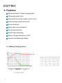
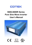
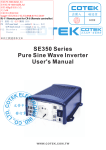
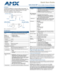
BP- A Series Switch-Mode 3 Stage Battery Charger User’s Manual Table of Contents 1. Important Safety Information……………………………………….………… 1 1-1 General Safety Precautions……………………………………………… 1 1-2 Battery Precautions………………………………...…………………….. 2 2. Features…………………………………………………………………………... 3 2-1 Battery Charging Curve………………………………………………….. 3 2-2 Electrical Characteristics…………..……..……………………………… 4 2-3 Mechanical Drawing..…………………………………………………….. 5 3. Instructions……………………………………………….……………………… 6 3-1 Front Panel Operation..…………………………………………………... 6 3-2 Rear Panel Operation..…………………………………………………… 7 3-3 Troubleshooting…………………………………………………………… 8 3-4 Battery Type Selections………………………………………………….. 8 ©Copyright :This manual is the copyright of COTEK Electronic lnd. Co., Ltd. copied without the express permission of the owner. And may not be reproduced or 1. Important Safety Information WARNING! Before installing or using BP- A Battery Charger, you need to read following safety information carefully. 1-1. General Safety Precautions 1-1-1. Do not expose BP-□□□□A Battery Charger to water, mist, snow, or dust. To reduce the risk of fire, do not cover or obstruct the ventilation shaft. Do not install BP-□□□□A Battery Charger in a zero-clearance Compartment. Overheating may occur. 1-1-2.To avoid the risk of fire and electronic shock, make sure that existing wiring is in good electrical condition and not undersize. Do not operate BP-□□□□A Battery Charger with damaged or substandard wiring. 1-1-3.Do not charge non-rechargeable batteries. 1-1-4.Do not charge batteries in a non-ventilated enclosures. 1-1-5.Only the wire with IEC socket i s allowed to plug to the battery charger. 1-1-6.If the power supply cord is damaged, it must be replaced by the manufacturer, the service agent, or a related qualified person in case of a hazard. 1 1-2. Battery Precautions 1-2-1.If battery acid contacts your skin or clothing, you shall wash it out with soap and water immediately. If battery acid contacts your eyes, you shall wash it out with cold running water for at 1 least 20 minutes and get medical attention immediately. 1-2-2.Never smoke or make a spark or flame in the vicinity of the battery or the engine. 1-2-3.Do not drop metals on the battery. The resulting spark or shortcircuit on the battery or other electrical parts may cause an explosion. 1-2-4.Remove personal metal items such as rings, bracelets, necklaces, and watches when operating with lead-acid batteries. Doing so may cause short circuit and very high temperature, which can melt metal items and even burn you. 2 2. Features High-performance 3-stage charging effect 0.98 typical power factor Advanced 8 bit microprocessor control circuit Reverse polarity protected by fuse Ignition protection Output short circuit protection Over power protection Switch mode technology Statue of charge indication by LED Compact and lightweight design 2-1. Battery Charging Curve 3 2-2. Electrical Characteristics Model Output Input BP-1210A BP-1205A BP-2405A BP-2403A DC Voltage Range 14.4V 14.4V 28.8V 28.8V Rated Current 10A 5A 5A 2.5A Current Range 0 ~ 10A 0 ~ 5A 0 ~ 5A 0 ~ 2.5A Rated Power (max.) 144W 72W 144W 72W Battery Charger Mode 3 - stage Battery Chargers ( Refer to Battery Charging Curve) Indication LED Refer to LED Status Voltage Range 88 ~ 264VAC Frequency Range 47Hz ~ 63Hz Efficiency ( Typ. ) at 230Vac 80% AC Current ( Max. ) 1.9 A / 90VAC Inrush Current ( Typ. ) Cold Start 30A / 230VAC Leakage Current < 0.75mA / 240VAC 0.95A / 180VAC 85°C ± 5°C ( TH1 ) detect on heat sink Over Temperature Protection type : Shut d temperature goes down own output voltage, recovers automatically after Working Temp. - 20°C ~ 50°C Working Humidity 20 ~ 90% RH non-condensing Environment Storage Temp., Humidity - 40 ~ +85°C Temp.Coefficient ± 0.03% / °C ( 0 ~ 50°C ) Vibration 10 ~ 500Hz, 1G 0.5Oct/min, period for 60min. Each along X,Y,Z axes Safety Standards IEC 60950-1, 1st Edition ( 2001 ) ; EN 60950-1, 1st Edition ( 2001+A11 ) Withstand Voltage I/P - O/P:3KVAC I/P - FG:1.5KVAC O/P-FG:0.5KVAC, 1 minute Isolation Resistance I/P - O/P, I/P - FG, O/P - FG:100M Ohms/500VDC EMI Conduction & Radiation EN 55022 : 2006 Class B Harmonic Current EMS Immunity Note 80% Protection type : Consta nt current lim iting, Hiccup m ode, recovers a utomatically after fault condition is removed Protection Others 83% 102~110% rated output power Over Load Safety & EMC 78% MTBF Compliance: MIL-HDBK-217F EN 61000-3-2 : 2006 ; EN 61000-3-3 :1995+A1 : 2001+A2 : 2005 ; EN 55024 : 1998+A1:2001+A2 : 2003 ; IEC 61000-4-2 Edition 1.2 : 2001 -04 ; IEC 6100 0-4-4 : 2004 IEC 61000-4-5 Edition 1.1 : 2001-0 4 ; IEC 6100 0-4-6 Edition 2.1 : 2004-1 1 IEC 61000-4-8 Edition 1.1 : 2001-03 ; IEC 61000-4-11 Second Edition : 2004-03 343.3 KHRS 343.1 KHRS 302.2 KHRS Dimension (L*W*H) (mm) 210 (L) x 85 (W) x 50 (H) mm / 8.26 (L) x 3.34 (W) x 1.96 (H) Inch Packing 1 kg. / 2.2 Lbs. 265.5 KHRS 1. All parameters NOT specially mentioned are measured at 230VAC input, rated load and 25℃ of ambient temperature. 2. The power supply is considered a component which will be installed into a final equipment. 3. The final equipment must be re-confirmed that it still meets EMC directives. *Note : The specifications are subject to change without notice. 4 2-3. Mechanical Drawing 5 3. Instructions BP-□□□□A series are high frequency switch-mode 3-stage battery chargers equipped with micro-controller and PFC circuit to manage battery intelligently and to provide highly reliable operations. Before using BP-□□□□A, read all instructions and precautions marking on this manual. 3-1. Front Panel Operation: 3-1-1.Front view: 0N I 0 AC INPUT 0FF IEC RECEPTACLE TYPE 0N I 0 AC INPUT 0FF POWER CORD TYPE 6 3-1-2.ON / OFF switch: Power ON / OFF switch, leave the status OFF during installation. 3-1-3.LED Status Charging Status LED Signal LED Indication Bulk Charge Fast Green Blink Absorption Charge Slow Green Blink Floating Charge Solid Green Charging Failure or Wire Disconnection Red Blink 3-2. Rear Panel Operation: PUSH DC O U TP U T DC FUSE STATUS 3-2-1.Ventilation Shaft: Be sure to keep it a distance (at least one inch) from surrounding things. 3-2-2.DC Output Terminals: Connect it to 12V/24V batteries. 【+】indicates positive, 【-】indicates negative. Reverse polarity connection will blow the internal fuse and may damage BP-□□□□A permanently. 7 3-3. Troubleshooting: Problems and Symptoms “Red” LED blink Possible Cause Battery is disconnected Polarity reverse LED light off Solutions Check the battery connection. Place proper polarity. Check DC fuse. If broken, replace the same rating fuse. DC fuse broken Check DC output fuse No AC power delivering Check input power connection. Make sure the ventilation shaft is not obstructed. Improve ventilation. Lower the temperature Surrounding it. Thermal shutdown 3-4. Battery Type Selections: Sealed lead acid and open lead acid batteries are as follows: Model No. Battery Capacity (Min.) Battery Capacity (Max.) BP-1205A 12V / 15Ah 12V / 50Ah BP-1210A 12V / 30Ah 12V / 100Ah BP-2403A 24V / 7.5Ah 24V / 25Ah BP-2405A 24V / 15Ah 24V / 50Ah 8 No. 33, Rong Hsin Rd., Pa Teh City, Tao Yuan County, Taiwan Phone:886-3-3661581 FAX:886-3-3676029 E-mail:[email protected] http:// www.cotek.com.tw 2005.08