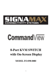
1
Signamax Connectivity Systems 16-Port 10/100 Dual Speed Ethernet Full Duplex Switch Model 065-7530 24-Port 10/100 Dual Speed Ethernet Full Duplex Switch Model 065-7540 U S E R ’ S G U I D E Signamax Connectivity Systems 16-Port 10/100 Dual Speed Ethernet Full Duplex Switch Model 065-7530 24-Port 10/100 Dual Speed Ethernet Full Duplex Switch Model 065-7540 User’s Guide FCC Warning This equipment has been tested and found to comply with the limits for a Class A digital device, pursuant to Part 15 of the FCC Rules. These limits are designed to provide reasonable protection against harmful interference when the equipment is operated in a commercial environment. This equipment generates, uses, and can radiate radio frequency energy and, if not installed and used in accordance with this user’s guide, may cause harmful interference to radio communications. Operation of this equipment in a residential area is likely to cause harmful interference in which case the user will be required to correct the interference at his own expense. CE Mark Warning This is a Class A product. In a domestic environment, this product may cause radio interference in which case the user may be required to take adequate measures. Signamax Connectivity Systems from Advanced Electronic Supports Products Inc. All rights reserved. All brand names are registered trademarks of their relative holders. Trademarks Product names mentioned in this manual may be trademarks or registered trademarks of those products and are hereby acknowledged. • Ethernet is a trademark of Xerox Corporation. • Microsoft Windows Corporation. is a trademark of Microsoft • VT100 is a trademark of Digital Equipment Corporation. • Signamax is a trademark of Advanced Electronic Support Products, Inc. TABLE OF CONTENTS ABOUT THIS GUIDE .................................................. 1 CHAPTER 1: INTRODUCTION.................................... 3 BENEFITS OF SWITCHING .............................................. 3 SIGNAMAX SWITCHES ................................................... 4 PRODUCT F EATURES ................................................... 5 PACKING L IST ............................................................. 6 FRONT PANEL ............................................................. 6 PORTS....................................................................... 8 EXPANSION MODULES .................................................. 9 LED INDICATOR .........................................................11 CHAPTER 2: INSTALLATION....................................14 SELECTING A SITE FOR S witches ..................................14 CONNECTING TO P OWER .............................................15 CONNECTING TO Y OUR N ETWORK .................................15 OPTIONAL MODULE INSTALLATION.................................17 JUMPER S ETTINGS ......................................................18 CHAPTER 3: SWITCH CONFIGURATION ..................19 SETTING UP THE CONSLE PORT CONNECTION .................20 VLAN.......................................................................23 CONFIGURE VLAN GROUPS ........................................25 PORT S ETTING ...........................................................28 MAC-BASED TRUNKING (16-PORT) ...............................31 PORT-BASED TRUNKING (24-PORT )...............................33 N ETWORKING EXAMPLES .............................................37 CHAPTER 4: SPECIFICATIONS ................................41 APPENDIX A: CONNECTOR PINOUTS .....................43 APPENDIX B: CONTACT INFORMATION..................44 Signamax 065-7530/065-7540 Full-Duplex Switches ABOUT THIS GUIDE This manual describes how to install and use Signamax 16-port (model 065-7530) and 24-port (model 065-7540) 10/100 Dual Speed Ethernet Full Duplex Switches. They feature either sixteen or twenty-four RJ-45 ports that auto negotiate the presence of 100/10Mbps and full or halfduplex mode. An optional 100BaseFX multi-mode or single-mode fiber optic module enables long-distance connection. To get the most out of this manual, you should have an understanding of networking concepts such as bridging, IEEE 802.3 Ethernet and 100BaseTX Fast Ethernet, and local area networks (LAN). For more information about these topics, please refer to the Appendices. In this manual, you will find: • Benefits of Ethernet switches • Model 065-7530 and 065-7540 and their features • LED functions illustration • Installation instructions • Configuration instructions for VLAN, Trunking and port speed • Specifications About This Guide 1 Signamax 065-7530/065-7540 Full-Duplex Switches • Ethernet technology, LAN, VLAN and Trunking tutorial information • Definitions of terms used in this manual 2 About This Guide Signamax 065-7530/065-7540 Full-Duplex Switches 1 INTRODUCTION Benefits of Switching Ethernet switching technology has dramatically boosted the total bandwidth of a network. It puts configuration flexibility and bandwidth adaptability into the local workgroups, where the majority of work is generated. It further eliminates congestion problems inherent to the CSMA/CD protocol, and improves predictable response time under heavy network loads. Expensive routing equipment was used in the past to reduce the congestion under heavy loads. The new wave of object-oriented client and server applications demands higher bandwidth and tighter integration of client workstations with servers. The old shared-access (hub/repeater) Ethernet technology provides neither enough bandwidth nor sufficiently predictable response time for this new wave of workgroup computing. Fast Ethernet switching not only satisfies both technical and business requirements, but also preserves the user’s existing investment in the huge 10BaseT Ethernet installed base. Introduction 3 Signamax 065-7530/065-7540 Full-Duplex Switches This compatibility ensures a path for users to add, change, and migrate to Fast Ethernet as demands emerge. It also provides a low cost and flexible bandwidth solution directly to local workgroups where the majority of work is generated, reducing the need for expensive network equipment. Signamax Switches As a Fast Ethernet switch, Signamax 16-port (model 0657530) and 24-port (model 065-7540) 10/100 Dual Speed Ethernet Full Duplex Switches have 16 and 24 10/100Mbps ports with an optional fiber-optic module, flexibly meeting fiber-optic needs. The straightforward design enables ease of operation while providing superior performance. Addressing the demand for fiber, Signamax provides an optional multi-mode or single -mode fiber module for the 0657530 and 065-7540 as an optimum solution for long-distance connectivity. The module supports one SC, ST, MT-RJ, or VF45 port. Signamax Switches represent the newest generation in Ethernet switching technology by supporting both 10Mbps and 100Mbps speed and half or full duplex transmission modes on the same port. By using standard auto-negotiation, Signamax provides both a cost-effective way of integrating legacy 10Mbps segments with 100Mbps Fast Ethernet networks, and an ideal solution for extending the distance between two 100Mbps network segments. 4 Introduction Signamax 065-7530/065-7540 Full-Duplex Switches Signamax 065-7530/065-7540 switches support portbased Virtual Local Area Networking (VLAN). This advanced feature gives the network administrator a powerful, yet easy-to-use tool to reduce unnecessary broadcast traffic, flexibly segment the network, and enhance network security. The Signamax 065-7530/0657540 switches fully comply with IEEE 802.3u, 100BaseTX/FX, and IEEE 802.3, 10BaseT standards. Product Features • 16 ports (065-7530) or 24 ports (065-7540) with NWay auto-negotiation of 10/100Mbps speed and duplex mode • Optional 1-port ST, SC, MT-RJ, or VF-45 module • Plug-and-play • True non-blocking architecture • Full wire speed forwarding • Store-and-forward mechanism • Back pressure and IEEE 802.3x compliant flow control • Supports 8K MAC addresses for 065-7530 • Supports 2K MAC addresses for 065-7540 • Port based VLAN & MAC based Trunking for 065-7530 • Port based VLAN & port based Trunking for 065-7540 • Programmable re-configuration for fixed speed and duplex modes • One uplink port activated by the push of a button • Front panel reset button Introduction 5 Signamax 065-7530/065-7540 Full-Duplex Switches • Front panel status LEDs • Standard 19" rack-mount size Packing List When you unpack this product, you should find the items listed below. Please inspect the contents, and report any apparent damage or missing items immediately to your authorized reseller. * Signamax 065-7530 or 065-7540 switch * User’s Manual * AC power cord * Rackmount Ears with screws * Serial Cable Front Panel The front panel of the Signamax 065-7530 and 065-7540 switches has 16 or 24 ports, one slot for an optional fiber module, and an array of LED indicators to provide you with instant feedback on the status of the switch. 6 Introduction Signamax 065-7530/065-7540 Full-Duplex Switches Figure 1: Front panel of 065-7530 Figure 2: Front panel of 065-7540 Introduction 7 Signamax 065-7530/065-7540 Full-Duplex Switches Ports The Signamax 065-7530/065-7540 switches contain 16/24 RJ-45 10/100 Ethernet ports and one slot for the optional module for fiber connection. The auto-negotiation feature of the 065-7530/065-7540 switches allows communication between 10BaseT (Ethernet) and 100BaseTX (Fast Ethernet) at full or halfduplex mode. If it is desirable to operate at a fixed, rather than auto-negotiated media setting, please refer to the Port Settings section on page 28. The optional module of the 065-7530/065-7540 switches provides an additional port for fiber ST, SC, MT-RJ, or VF-45. The latter are fiber-optic small-form-factor connectors that are smaller and easier to use. The optional module port also allows the use of single-mode fiber for distances up to 75 km. For information on module installation, please refer to page 17. The maximum range of a 100BaseTX network connected to the switch is 100 meters with Category 5 unshielded twisted-pair (UTP) cable. A 10BaseT network may range up to 100 meters with Category 3, 4, or 5 UTP cable. As for the length of fiber link between a switch and a Data Terminal Equipment, it is capable to span up to 2 kilometers (1.24 Mile) using 50/125 or 62.5/125-micron multi-mode fiber-optic cable or up to 15/40/75 kilometers using 9/125 or 10/125 micron single-mode fiber optic cable in full-duplex mode. 8 Introduction Signamax 065-7530/065-7540 Full-Duplex Switches Expansion Modules The following is a list of model numbers for the various modules. All TX ports use RJ-45 connectors. Table 1: Module Model Number Model Ports FO-065-75ST 100BaseFX FO-065-75SC 100BaseFX FO-065-75MT 100BaseFX FO-065-75VF 100BaseFX FO-065-75SM 100BaseFX FO-065-75SMED 100BaseFX Introduction FX Connector ST SC MT-RJ VF-45 SC(Single Mode, 15Km) SC(Single Mode, 40Km) 9 Signamax 065-7530/065-7540 Full-Duplex Switches Table 2: Module Type and Specification Speed Connector Port Speed Half/Full Duplex Cable Distance 10BaseT RJ-45 10/20 Mbps Category 3, 4, or 5 UTP 100 meters 100BaseTX RJ-45 100/200 Mbps Category 5 UTP 100 meters 100BaseFX (Multi mode) ST, SC, MT-RJ, VF-45 100/200 Mbps 50/125 or 62.5/125 micron multimode fiber 2 km 100BaseFX SC 100/200 Mbps 9/125 or 10/125 micron singlemode fiber 15/40/75 km (Single mode) 10 Introduction Signamax 065-7530/065-7540 Full-Duplex Switches LED Indicator The array of LED indicators on the front panel conveys status and configuration information to help you monitor and trouble-shoot the switch. Figure 3: 065-7530/065-7540 Front Panel and LED Indicators Introduction 11 Signamax 065-7530/065-7540 Full-Duplex Switches Œ Power This LED comes on when the switch is connected to a power supply and turned on. • Reset Button If the Signamax 065-7530/065-7540 switches should become unresponsive, you may perform a reset of the switch by pressing this button. Ž Port Status The front panel of Signamax 065-7530 has two segments of eight ports numbered from 1X to 16X and 065-7540 has three segments of eight ports numbered from 1X to 24X. The LEDs are located at the left side of each segment, display status for each respective port. Consult the following chart for clarification. • Uplink Button Depress to connect to another switch or hub. Affects port 16X for 065-7530 or port 24X for 065-7540 only. • Optional Module LEDs Status A set of three LEDs displays the status of the optional modular port. Consult the following chart for clarification. 12 Introduction Signamax 065-7530/065-7540 Full-Duplex Switches Table 3: Port Status LED LNK/ACT State Indication Steady LINK: The port has established a valid network connection ACTIVITY: The port is transmitting or receiving data 100Mbps: The port has established a valid 100Mbps network connection 10Mbps:The port has established a valid 10Mbps network connection. FULL-DUPLEX: The connection is in full duplex mode COLLISION: Collision occurred in the 10/100 domain. The connection is in half duplex mode Flashing Steady 100 Off Steady FDX/COL Flashing Off Table 4: Optional module port status LED State Indication Steady 100Mbps: The port has established a valid network connection Flashing The port is transmitting data Steady 10Mbps: The port has established a valid network connection Flashing The port is receiving data 100/TX 10/RX FDX/COL Steady Flashing The connection is in full duplex mode COLLISION: Collision occurred in the 10/100 domain. Introduction 13 Signamax 065-7530/065-7540 Full-Duplex Switches 2 INSTALLATION This chapter presents step-by-step installation instructions for the Signamax 065-7530/065-7540 switches. Selecting a Site for the Switch As with any electronic device, you should place the Signamax 065-7530/065-7540 switch where it will not be subjected to extreme temperatures, humidity, or electromagnetic interference. Specifically, the site you select should meet the following requirements: • The room temperature should be between 32 and 104 degrees Fahrenheit (0 to 40 degrees Celsius). • The relative humidity should be less than 90 percent, non-condensing. • Surrounding electrical devices should not exceed the electromagnetic field (RFC) standards for IEC 801-3, Level 2 (3V/M) field strength. • Make sure that the switch receives adequate ventilation. Do not block the ventilation holes on the side of the switch or the fan exhaust port on the rear of the switch. The power outlet should be within 1.8 Meter of the switch. 14 Installation Signamax 065-7530/065-7540 Full-Duplex Switches Detailed specifications may be found on page 41. Connecting to Power Connect the supplied AC power cord to the receptacle on the back of the switch, and then plug the cord into a standard AC outlet with a voltage range from 100 to 240 VAC. Turn the 065-7530/065-7540 unit on by flipping the ON/OFF switch on the rear of the unit to the I (ON) position. The O position is OFF. Connecting to Your Network Obtain or prepare cables with corresponding connectors for each type of port in use. Consult Table 5 below for cabling requirements based on connectors and speed. Once the connections are made, the switch is operational. Installation 15 Signamax 065-7530/065-7540 Full-Duplex Switches Table 5: Cable Specifications Speed Connector Port Speed Half/Full Duplex Cable Distance 10BaseT RJ-45 10/20 Mbps Category 3, 4, or 5 UTP 100 meters 100BaseTX RJ-45 100/200 Mbps Category 5 UTP 100 meters 100BaseFX ST, SC, MT-RJ, VF-45 100/200 Mbps 50/125 or 62.5/125 micron multimode fiber 2 km SC 100/200 Mbps 9/125 or 10/125 micron singlemode fiber 15/40/75 km (Multi mode) 100BaseFX (Single mode) When the uplink button is pressed down, port 16X (for 065-7530) or 24X (for 065-7540) can be used to connect to any port of another hub or switch. To connect two regular RJ-45 ports between any switches or hubs, you need a cross-wire cable. The cable must be a Category 5 shielded twisted-pair or unshielded twisted-pair (STP/UTP) cable for 100BaseTX, or Category 3, 4, or 5 STP/UTP cable for 10BaseT. 16 Installation Signamax 065-7530/065-7540 Full-Duplex Switches Optional Module Installation Signamax 065-7530/065-7540 offers an optional one-port module for fiber connection. The fiber module is available in either single or multi-mode; it supports either a MT-RJ, SC, ST, or VF-45 connector. The optional module should be inserted into the extension slot located at the right side of the switch. Port 20X (for 065-7540) will be automatically disabled when optional module is installed. Before installation, ensure that the power is disconnected. The module is not hot-swappable. Unscrew the cover plate in the extension slot. Pull out the cover plate, which has a nonwired board attached. Slide the module in slowly, following the metal guides. Once it is slid in fully, snap in the module to make a proper connection and tighten the screws. Figure 4: Removal of cover plate Figure 5: Module being installed Installation 17 Signamax 065-7530/065-7540 Full-Duplex Switches Jumper Settings The module arrives with pre-set jumpers and should not be reset. Use the jumper settings for trouble-shooting purposes only. Figure 6: Proper jumper settings for fiber module 18 Installation Signamax 065-7530/065-7540 Full-Duplex Switches 3 SWITCH CONFIGURATION This section explains the configuration of VLAN, flowcontrol, and port speed and duplex mode setting. Virtual Local Area Networking (VLAN) enables efficient traffic separation, provides better bandwidth utilization, and alleviates scaling issues by logically segmenting the physical LAN so that packets are switched only between ports within the same VLAN. This also creates secure segments within the existing network. Nodes residing in different VLAN segments cannot communicate with each other although they are connected to the same switch. The resulting security is yet another reason to use VLAN. Auto-negotiation adjusts the speed and the duplex mode of each port, based on the capability of connected devices. Flow control, or back pressure, regulates transmission between two nodes running at different speeds or duplex modes. Auto-negotiation and flowcontrol may require disabling for some operations involving legacy equipment. Disabling the autonegotiation is accomplished by fixing the speed or duplex mode of a port. Disabling of flow control is also performed on an individual port basis. Switch Configuration 19 Signamax 065-7530/065-7540 Full-Duplex Switches Setting up Connection the Console Port To configure these features through the console port, it is necessary to first configure a terminal emulation program in DOS or in Windows, such as HyperTerminal. Check the switch, cables, and computers for proper installation before configuration. Attach a PC or any VT100 compatible terminal to the console port on the back of the switch (see figure 7) using the following settings: Terminal Type VT100 Port Type (COM 1~4) Communication Mode 8 data bits, 1 stop bit, no parity and 9600bps (for initial configuration) Flow Control None Hardware Compression NA Console Port Figure 7. Console Port 20 Switch Configuration Signamax 065-7530/065-7540 Full-Duplex Switches Turn on the switch and press any key to view the main menu shown below: 24-port 10/100 Base Ethernet Switch VLAN Port List V1, 1,2,3,4,5,6,7,8,9,10,11,12,13,14,15,16,17,18,19,20,21,22,23,24 V2 < empty > V3 < empty> V4 < empty > Port Mode FLW VLAN Port 1 Auto Y V1 13 2 Auto Y V1 14 3 Auto Y V1 15 4 Auto Y V1 16 5 Auto Y V1 17 6 Auto Y V1 18 7 Auto Y V1 19 8 Auto Y V1 20 9 Auto Y V1 21 10 Auto Y V1 22 11 Auto Y V1 23 12 Auto Y V1 24 VLAN/Mode/Trunking/Default (V/M/T/D) ? Mode FLW VLAN Auto Auto Auto Auto Auto Auto Auto Auto Auto Auto Auto Auto V1 V1 V1 V1 V1 V1 V1 V1 V1 V1 V1 V1 Y Y Y Y Y Y Y Y Y Y Y Y Mode = Speed and Duplex mode FL = Flow Control This main menu shows you the default configuration of the switch. By default, all ports are set at autonegotiation, flow control on, and all ports are grouped into V1 (VLAN group 1). Switch Configuration 21 Signamax 065-7530/065-7540 Full-Duplex Switches These are the valid commands: [V] Configure VLAN groups [M] Select 10/100Mbps and half or full-duplex mode [T] Select Trunking [D] Restore the default settings [ESC] Abort the menu at any time 22 Switch Configuration Signamax 065-7530/065-7540 Full-Duplex Switches VLAN Virtual local area network (VLAN) is a network configuration in which nodes are grouped into logical, rather than physical networks. Figure 8 & 9 below shows the difference between LAN and VLAN. The segmentation in VLAN creates secured areas where sensitive information is not shared and creates its own broadcast domain within the group to effectively reduce broadcast traffic, providing higher network efficiency and security. Figure 8: LAN Segmentation Switch Configuration 23 Signamax 065-7530/065-7540 Full-Duplex Switches Figure 9: VLAN Segmentation 24 Switch Configuration Signamax 065-7530/065-7540 Full-Duplex Switches Configure VLAN Groups Virtual Local Area Networks (VLANs) enable segmenting of the LAN without regard to physical location. Assign each port to a VLAN group or set of groups according to accessibility needs. Thus, a specific port could be in more than one VLAN group. This switch is able to support up to four port-based Virtual LAN (VLAN) domains. Follow these steps to assign ports to a VLAN group. • Enter [V] from the Main Menu • Select a VLAN group: [V1], [V2], [V3], or [V4] • Enter the port #. Note: If entering more than one port to a VLAN group, separate each port # by commas without spaces. Only one VLAN group can be defined at a time. Repeat selecting VLAN groups and assigning ports until all ports are assigned to at least one VLAN group. Though each VLAN grouping does not need to be utilized, each port must be assigned to at least one VLAN group. Hit the [ESC] key when done. To return to the default settings (in which each port is assigned to V1), enter [D] from the main menu. A prompt appears to verify this action. Switch Configuration 25 Signamax 065-7530/065-7540 Full-Duplex Switches VLAN Example: VLAN/Mode/Trunking/Default (V/M/T/D)? V Please enter the VLAN# or ESC to abort (V1-V4) -> V1 The current V1 is 1,2,3,4,5,6,7,8,9,10,11,12,13,14,15,16 Please enter the new port list -> • Key 1,2,3,8,10,14,15,17,18,19,20,22 Proceed with the assignment of the remainder of the ports into any VLAN grouping: • Enter [V2] • Key 1,4,5,6,8,12,13,19,21,23 • Enter [V3] • Key 1,7,9,11,16,19,21,23 Note: Until assigned, the menu displays **error** for each unassigned port. While any port is in the **error** status, the [ESC] key will not return the screen to the main menu. Assign each port to a VLAN grouping prior to exiting the program. 26 Switch Configuration Signamax 065-7530/065-7540 Full-Duplex Switches View the results on the following illustration. 24-port 10/100 Base Ethernet Switch VLAN Port List V1, 1,2,3,4,5,6,7,8,9,10,11,12,13,14,15,16,17,18,19,20,21,22,23,24 V2 < empty > V3 < empty> V4 < empty > Port Mode FLW VLAN Port Mode FLW 1 Auto Y V1 V2 V3 13 2 Auto Y V1 14 3 Auto Y V1 15 4 Auto Y V2 16 5 Auto Y V2 17 6 Auto Y V2 18 7 Auto Y V3 19 8 Auto Y V1 V2 20 9 Auto Y V3 21 10 Auto Y V1 22 11 Auto Y V3 23 12 Auto Y V2 24 VLAN/Mode/Trunking/Default (V/M/T/D) ? Auto Auto Auto Auto Auto Auto Auto Auto Auto Auto Auto Auto Y Y Y Y Y Y Y Y Y Y Y Y VLAN V2 V1 V1 V3 V1 V1 V1 V2 V3 V1 V2 V3 V1 V2 V3 ??Error Note: Port 24 is not defined to any VLAN, so “Error” appears and the switch can’t work normally. When setting VLAN, each port needs to be defined to at least one of the VLANs. Switch Configuration 27 Signamax 065-7530/065-7540 Full-Duplex Switches Port Setting The duplex and speed settings can be altered and the flow control can be turned off to accommodate special needs. Follow these steps to change the speed/duplex mode setting or to toggle flow control ON/OFF: • Enter [M] (no [ENTER]) • Select a port • Select the media from the list that appears on the screen Note: Only one port can be changed at a time. Consult the following chart for a brief description: # Communication Media Description 0 Flow control Toggles off/on 1 Auto Auto-Negotiation 2 100FD 100Mbps at full duplex mode 3 100HD 100Mbps at half duplex mode 4 10FD 10Mbps at full duplex mode 5 10HD 10Mbps at half duplex mode 28 Switch Configuration Signamax 065-7530/065-7540 Full-Duplex Switches Example: • Enter [M] • Select port 6 • Select communication media 5 View the results on the following illustration. 24-port 10/100 Base Ethernet Switch VLAN Port List V1, 1,2,3,4,5,6,7,8,9,10,11,12,13,14,15,16,17,18,19,20,21,22,23,24 V2 < empty > V3 < empty> V4 < empty > Port Mode FLW VLAN Port Mode FLW 1 Auto Y V1 V2 V3 13 2 Auto Y V1 14 3 Auto Y V1 15 4 Auto Y V2 16 5 Auto Y V2 17 6 10HD Y V2 18 7 Auto Y V3 19 8 Auto Y V1 V2 20 9 Auto Y V3 21 10 Auto Y V1 22 11 Auto Y V3 23 12 Auto Y V2 24 VLAN/Mode/Trunking/Default (V/M/T/D) ? Auto Auto Auto Auto Auto Auto Auto Auto Auto Auto Auto Auto Switch Configuration Y Y Y Y Y Y Y Y Y Y Y Y VLAN V2 V1 V1 V3 V1 V1 V1 V2 V3 V1 V2 V3 V1 V2 V3 V1 29 Signamax 065-7530/065-7540 Full-Duplex Switches When the optional module is being used, port 20 (for 065-7540) will be automatically disabled however, on the program of the switch configuration, port #20 will be showing the status of the optional module. The port setting for the optional module is slightly different from the regular port. Consult the following chart for a brief description: # Communication Media Description 0 Flow control Toggles off/on 1 FX FD 2 FX HD 30 100Mbps at full duplex mode 100Mbps at half duplex mode Switch Configuration Signamax 065-7530/065-7540 Full-Duplex Switches MAC-based Trunking (16-Port) The Signamax 065-7530 switch provides a MAC-Based Trunking function, which is capable of a trunking group of either 2 to 4 ports. This makes a maximum bandwidth connection of 800Mbps (Full-Duplex). The MAC address is the address of the network interface card. When the packet is transmitting, it will contain the source address and destination address of the NIC. The combination of source and destination address give the switches a direction to determine the trunking ports to depart from if the destination address is on another switch. Trunking Rules There are some rules for MAC-Based Trunking setting: a. FO-065-7530 provides two ways of trunking selection: two port-trunking (Port #s 1 & 5) and four-port trunking (Port #s 1, 2, 5 & 6), providing a high bandwidth connection from 400Mbps to 800Mbps. b. Trunking port setting is only available for Port #s 1, 2, 5, & 6. c. For MAC-Based Trunking, it requires two MAC-Based Trunking switches to parallel, and all the trunking ports must be linked together in order to function properly. Therefore, one MAC-Based Trunking switch cannot have the trunking function enabled unless another MAC-Based Trunking switch has enabled its trunking ports. Switch Configuration 31 Signamax 065-7530/065-7540 Full-Duplex Switches MAC-based Trunking Setting Follow these steps to configure trunking. • Enter [T] • Select [1] for 2-port trunking or select [2] for 4-port trunking View the results on the following illustration. 16-port 10/100 Base Ethernet Switch VLAN/Mode/Trunking/Default (V/M/T/D)? T 0 disable 1. 2-port 2. 4-port Select Trunking Group (0-2)? 2 VLAN Port List V1 1,2,3,4,5,6,7,8,9,10,11,12,13,14,15,16 V2<empty> V3 <empty> V4 <empty> Port Mode FLW 1 2 Auto Auto Y Y 3 4 5 Auto Auto Auto Y Y Y 6 7 8 Auto Auto Auto Y Y Y VLAN LIST Port Mode FLW V1 V1 9 10 Auto Auto Y Y V1 V1 TRUNK V1 V1 V1 11 12 13 Auto Auto Auto Y Y Y V1 V1 V1 V1 V1 V1 14 15 16 Auto Auto Auto Y Y Y V1 V1 V1 TRUNK VLAN/Mode/Trunking/Default (V/M/T/D)? 32 VLAN LIST TRUNK TRUNK Switch Configuration Signamax 065-7530/065-7540 Full-Duplex Switches Port-based Trunking (24-Port) The FO-065-7540 switch provides you the capability of trunking either 2 or 4 ports, totaling either a 400 Mbps or an 800 Mbps (Full-Duplex) bandwidth connection. Trunking Rules There are some rules for setting Trunking: a. When configuring Trunking, the VLAN function will be automatically disabled for the entire switch. b. FO-065-7540 provides two selections of trunking: twoport trunking (Port #s 1 & 2) and four port -trunking (Port #s 1, 2, 3 & 4), providing a high bandwidth connection from 400 Mbps to 800 Mbps. c. Trunking port setting is only available for Port #s 1, 2, 3 & 4. d. Trunking port must connect to any ports on another device (FO-065-7520 / 065-7530 / 065-7540) with the trunking setting disabled (Port 1, 2, 3, 4 for FO-0657530/065-7540, Port A1, A2, A3, A4 for FO-065-7520) or any ports except Port 1, 2, 3 & 4 (or A1, A2, A3 & A4 for FO-065-7520). That means when using Trunking, the ports connected in the two switches can’t be set as a trunking port at the same time; only one switch’s ports need to be defined as trunking ports, and the other switch’s ports have trunking disabled. e. Trunking port can connect to Signamax 10BaseT Hubs, 100BaseTX Hubs, 10/100 Dual speed Hubs, Desktop Switches, or any device without a trunking function. Switch Configuration 33 Signamax 065-7530/065-7540 Full-Duplex Switches Port-based Trunking Setting Follow these steps to configure trunking. • Enter [T] • Select [A] for 2-port trunking or select [B] for 4-port trunking View the results on the following illustration. 24-port 10/100 Base Ethernet Switch VLAN/Mode/Trunking/Default (V/M/T/D) ? Select Trunk Port A. 1, 2 B. 1, 2, 3, 4 ?A Port 1 2 3 4 5 6 7 8 9 10 11 12 Mode Auto Auto Auto Auto Auto 10HD Auto Auto Auto Auto Auto Auto FLW Y Y Y Y Y Y Y Y Y Y Y Y Port Trunk Trunk 13 14 15 16 17 18 19 20 21 22 23 24 VLAN/Mode/Trunking/Default (V/M/T/D)? 34 Mode FLW Auto Auto Auto Auto Auto Auto Auto Auto Auto Auto Auto Auto Switch Configuration Y Y Y Y Y Y Y Y Y Y Y Y Signamax 065-7530/065-7540 Full-Duplex Switches Port-Based and MAC -Based Trunking Difference Port-Based Trunking was developed based upon the idea of using the physical ports on a port-based trunking switch that could work with another switch without the trunking function. This makes trunking simpler to implement in an environment where a variety of switches are used. When trunking is enabled on a Port-Based Trunking switch, it can parallel-link to another switch with or without this feature -- but once the port-based trunking is enabled, the VLAN on the Port-Based Trunking switch will be disabled. Using the MAC-Based Trunking approach, the trunking and VLAN functions can work together without any problem. Where the trunking and VLAN functions need to be used together, the MAC-Based Trunking approach works more effectively than the Port -Based Trunking switch. Switch Configuration 35 Signamax 065-7530/065-7540 Full-Duplex Switches Figure 10: Trunking between two 065-7540s and Server Figure 11: Cascading with Trunking Port Connection 36 Switch Configuration Signamax 065-7530/065-7540 Full-Duplex Switches Networking Examples The following illustrates ways in which the 065-7530 and 065-7540 switches can be utilized: Figure 12: High-speed connections for a small workgroup Switch Configuration 37 Signamax 065-7530/065-7540 Full-Duplex Switches Figure 13: Collapsed backbone for workgroups 38 Switch Configuration Signamax 065-7530/065-7540 Full-Duplex Switches Figure 14: Bridging existing hub-based 100BaseTX and 10BaseT networks Switch Configuration 39 Signamax 065-7530/065-7540 Full-Duplex Switches Figure 15: Use FO-065-7540 and FO-065-7520 (MediaRack Switch System) to Define High Fiber Port Density Configuration 40 Switch Configuration Signamax 065-7530/065-7540 Full-Duplex Switches 4 SPECIFICATIONS 065-7530/065-7540 16/24-Port 10/100 Ethernet Switch Applicable Standards 10BaseT, IEEE 802.3 100BaseTX & 100BaseFX, IEEE 802.3u Ports 16 (for 065-7530) / 24 (for 065-7540) 10/100BaseT/TX 200Mbps full-duplex 100BaseFX: 100Mbps half-duplex Speed 100BaseTX: 200Mbps full-duplex 100Mbps half-duplex 10BaseTX: 20Mbps full-duplex 10Mbps half-duplex Performance 148,800bps forwarding rate per port for 100Mbps. LED Indicators Power, Link, Activity, 100Mbps, Fullduplex, Collision Module LED Indicators 100/TX, 10/RX, FDX/COL Dimensions 440 X 205 X 45 mm Rackmount Size 17.3 X 8.1 X 1.8 in. Rackmount Size Specifications 41 Signamax 065-7530/065-7540 Full-Duplex Switches Weight 2.6kg/5.7lb(for 065-7530) 2.9kg/6.4lb(for 065-7540) Power Input 100 ~ 250 VAC, 47/63 Hz, 2 A Power Consumption 15 W for FO-065-7530 25 W for FO-065-7540 Operating Temperature 0° ~ 40°C Humidity 10 ~ 90%, non-condensing Altitude 3048 m 32° ~ 104°F 10,000 ft 42 Emissions FCC part 15 Class A, CISPR Class A, VCCI-I CE Mark Safety UL, CSA, TUV/GS Specifications Signamax 065-7530/065-7540 Full-Duplex Switches A CONNECTOR PINOUTS Pin arrangement of RJ-45 connectors Figure 16: RJ-45 Connector and Cable Pins The following table lists the pinout of 10/100BaseT/TX ports: Table 6: Connector Pinouts Pin Regular Ports 1 Input Receive Data + 2 Input Receive Data 3 Output Transmit Data + 4 NC 5 NC 6 Output Transmit Data 7 NC 8 NC Uplink port Output Transmit Data + Output Transmit Data Input Receive Data + NC NC Input Receive Data NC NC Connector Pinouts 43 Signamax 065-7530/065-7540 Full-Duplex Switches B CONTACT INFORMATION SIGNAMAX CONNECTIVITY SYSTEMS An AESP Company 1810 N.E. 144th Street. North Miami, Florida 33181, U.S.A. Phone: 305-944-7710 Fax: 305-652-8489 Sales: 800-446-2377 Tech. Support: 800-446-2377, ext. 201 Http:\\www.signamax.com E-mail: [email protected] EUROPE AESP Ukraine. (UKRAINE) 2 Timiryazevskaya St. 47 252014 Kiev, Ukraine Phone: +380 44 296.53.57 Fax: +380 44 294.88.60 Http:\\www.aesp.com.ua E-mail: [email protected] AESP Sweden. (SWEDEN) Grevegatan 19-21 SE-815 40 TIERP. SWEDEN Phone:+46-(0)-293-228 88 Fax:+46-(0)-293-228 89 Phone:+49-81-35-9303-0 Http:\\www.aesp.se E-mail: [email protected] 44 AESP Russia. (RUSSIA) Kronshtadtsky Blv. 125499 Moscow, Russia Phone:+7 095-456-0704 Phone:+7 095-456-0344 Fax:+7 095-454-3040 Http:\\www.aesp.ru E-mail: [email protected] AESP Germany GmbH (GERMANY) Weisserfelderstr.2 D-85551 Kircheim b. München, Germany Phone:+49-89-901-097-0 Fax:+49-89-901-097-22 E-mail: [email protected] Contact Information Signamax 065-7530/065-7540 Full-Duplex Switches JOTEC AESP AS. (NORWAY) Telefon 23 14 17 00 Ordrefax 23 14 17 10 Karihaugveien 102 Postboks 50 Ellingsrudasen 1006 Oslo, Norway Phone:+47-23-14-1700 Fax:+47-23-14-1710 Http:\\www.jotec.no E-mail: [email protected] Contact Information 45