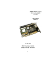
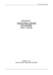
1
TECHNICAL USER'S MANUAL FOR: PC/104 PERIPHERAL BOARD MSMM104 Nordstrasse 11/F CH- 4542 Luterbach Tel.: ++41 (0)32 681 58 00 Fax: ++41 (0)32 681 58 01 Email: [email protected] Homepage: http://www.digitallogic.com DIGITAL-LOGIC AG MSMM104 Manual V1.3 COPYRIGHT 1992- 2000 BY DIGITAL-LOGIC AG No part of this document may be reproduced, transmitted, transcribed, stored in a retrieval system, in any form or by any means, electronic, mechanical, optical, manual, or otherwise, without the prior written permission of DIGITAL-LOGIC AG. The software described herein, together with this document, are furnished under a license agreement and may be used or copied only in accordance with the terms of that agreement. Any information in this manual and of the product are subject to change without notice. REVISION HISTORY: Prod.-Serialnumber: From: To: Product Version V1.1 V1.1 V2.0 V2.1a Document Version V1.0 V1.1 V1.2 V1.3 Date/Vis: 05.97 01.00 STP 04.2000 STP 12.2000 STP Modification: Remarks, News, Attention: Initial Version Jumper description added New board, new sound chip New board Product Registration: Please register your product at: http://www.digitallogic.com -> SUPPORT -> Product Registration After registration, you will receive driver & software updates, errata information, customer information and news from DIGITAL-LOGIC AG products automatically. 2 DIGITAL-LOGIC AG MSMM104 Manual V1.3 Table of Contents 1 1.1 1.2 1.3 1.4 1.5 1.6 1.7 2 2.1 2.2 2.3 2.4 2.5 3 3.1 3.2 PREFACE ............................................................................................................................ 4 HOW TO USE THIS MANUAL ................................................................................................................ 4 TRADEMARKS ................................................................................................................................... 4 DISCLAIMER ..................................................................................................................................... 4 W HO SHOULD USE THIS PRODUCT ..................................................................................................... 4 RECYCLING INFORMATION ................................................................................................................. 5 TECHNICAL SUPPORT ....................................................................................................................... 5 LIMITED W ARRANTY ......................................................................................................................... 5 OVERVIEW.......................................................................................................................... 6 ORDERING INFORMATION .................................................................................................................. 6 GENERAL INFORMATION .................................................................................................................... 6 FEATURES OF THE SOUNDBOARD, V2.0 AND V2.1 ............................................................................. 6 FEATURES OF THE SOUNDBOARD, V1.0............................................................................................. 7 RELATED APPLICATION NOTES .......................................................................................................... 7 MECHANICAL DIMENSIONS.............................................................................................. 8 BOARDVERSION V2.1A...................................................................................................................... 8 BOARDVERSION V2.0........................................................................................................................ 9 4 PC/104 BUS SIGNALS ...................................................................................................... 10 5 INSTALLING THE MSMM104 SOUNDCARD.................................................................... 12 5.1 5.2 6 CHECK THE HARDWARE AND SYSTEM REQUIREMENTS ...................................................................... 12 INSTALLING THE BOARD ................................................................................................................... 12 SOFTWARE DRIVER INSTALLATION.............................................................................. 13 6.1 BOARDVERSION V2.0 / V2.1...................................................................................................... 13 6.1.1 DOS Driver ............................................................................................................................ 13 6.1.2 WIN311, OS2, WIN95, WIN98, WIN NT ............................................................................... 14 6.1.3 Frequency response ............................................................................................................. 15 6.2 BOARDVERSION V1.0 ................................................................................................................ 16 6.2.1 Driver for WIN 3.11 ............................................................................................................... 16 6.2.2 Driver for WIN 95 .................................................................................................................. 16 6.2.3 Driver for NT4.0..................................................................................................................... 17 6.2.4 Bundled Applications, MediaRack ......................................................................................... 17 7 CONNECTORS.................................................................................................................. 18 7.1 THE CONNECTORS OF THE MSMM104, V2.1A ................................................................................. 18 7.2 JUMPERDESCRIPTION ..................................................................................................................... 23 7.3 JUMPERLOCATION........................................................................................................................... 24 7.4 THE CONNECTORS OF THE MSMM104, V2.0................................................................................... 25 7.4.1 Jumper location ..................................................................................................................... 30 The part schematics of the MSMM104, V2.0 .......................................................................................... 31 7.5 THE CONNECTORS OF THE MSMM104, V1.0................................................................................... 32 7.5.1 Amplifier Speaker Output ...................................................................................................... 32 7.5.2 Line Input............................................................................................................................... 32 7.5.3 Line Output............................................................................................................................ 32 7.5.4 Microphone Input................................................................................................................... 32 7.5.5 CD Input ................................................................................................................................ 32 7.5.6 BASS BOOST ....................................................................................................................... 32 7.5.7 EEPROM............................................................................................................................... 32 7.5.8 MASTERVOLUME ................................................................................................................ 32 7.5.9 SERIALPORT, IIS ................................................................................................................. 32 7.5.10 Gameport and Midi................................................................................................................ 33 7.6 THE PART SCHEMATICS OF THE MSMM104, V1.0............................................................................ 34 8 INDEX ................................................................................................................................ 35 3 DIGITAL-LOGIC AG 1 MSMM104 Manual V1.3 PREFACE This manual is for integrators and programmers of systems based on the MicroSpace card family. It contains information on hardware requirements, interconnections, and details of how to program the system. The specifications given in this manual were correct at the time of printing; advances mean that some may have changed in the meantime. If errors are found, please notify DIGITAL-LOGIC AG at the address shown on the title page of this document, and we will correct them as soon as possible. 1.1 How to use this manual This manual is written for the original equipment manufacturer (OEM) who plans to build computer systems based on the single board MicroSpace-PC. It provides instructions for installing and con-figuring the MSMM104 board, and describes the system and setup requirements. 1.2 Trademarks Chips & Technologies MicroSpace, MicroModule DOS Vx.y, Windows PC-AT, PC-XT NetWare Ethernet DR-DOS, PALMDOS ROM-DOS 1.3 SuperState R DIGITAL-LOGIC AG Microsoft Inc. IBM Novell Corporation Xerox Corporation Digital Research Inc. / Novell Inc. Datalight Inc. Disclaimer DIGITAL-LOGIC AG makes no representations or warranties with respect to the contents of this manual and specifically disclaims any implied warranty of merchantability or fitness for any particular purpose. DIGITAL-LOGIC AG shall under no circumstances be liable for incidental or consequential damages or related expenses resulting from the use of this product, even if it has been notified of the possibility of such damage. DIGITAL-LOGIC AG reserves the right to revise this publication from time to time without obligation to notify any person of such revisions. If errors are found, please contact DIGITAL-LOGIC AG at the address listed on the title page of this document. 1.4 - - Who should use this product Electronic engineers with know-how in PC-technology. Without electronic know-how we expect you to have questions. This manual assumes, that you have a general knowledge of PC-electronics. Because of the complexity and the variability of PC-technology, we can’t give any warranty that the product will work in any particular situation or combination. Our technical support will help you to may find a solution. Pay attention to the electrostatic discharges. Use a CMOS protected workplace. Power supply OFF when you are working on the board or connecting any cables or devices. This is a high technology product. You need know-how in electronics and PC-technology to install the system ! 4 DIGITAL-LOGIC AG 1.5 MSMM104 Manual V1.3 Recycling Information Hardware: - Print: epoxy with glass fiber wires are of tin-plated copper - Components: ceramics and alloys of gold, silver check your local electronic recycling - no problems: re-use the diskette after formatting Software: 1.6 Technical Support DIGITAL-LOGIC AG smartModule DesignIn Center Nordstr. 11/F CH-4542 Luterbach (SWITZERLAND) Fax: ++41 32 681 58 01 E-Mail: [email protected] Internet www.digitallogic.com Support request form (fill in and send via fax to DIGITAL-LOGIC AG support center): 1.7 Limited Warranty DIGITAL-LOGIC AG warrants the hardware and software products it manufactures and produces to be free from defects in materials and workmanship for one year following the date of shipment from DIGITAL-LOGIC AG, Switzerland. This warranty is limited to the original product purchaser and is not transferable. During the one year warranty period, DIGITAL-LOGIC AG will repair or replace, at its discretion, any defective product or part at no additional charge, provided that the product is returned, shipping prepaid, to DIGITAL-LOGIC AG. All replaced parts and products become property of DIGITAL-LOGIC AG. Before returning any product for repair, customers are required to contact the company. This limited warranty does not extend to any product which has been damaged as a result of accident, misuse, abuse (such as use of incorrect input voltages, wrong cabling, wrong polarity, improper or insufficient ventilation, failure to follow the operating instructions that are provided by DIGITAL-LOGIC AG or other contingencies beyond the control of DIGITAL-LOGIC AG), wrong connection, wrong information or as a result of service or modification by anyone other than DIGITAL-LOGIC AG. Neither, if the user has not enough knowledge of these technologies or has not consulted the product manual or the technical support of DIGITAL-LOGIC AG and therefore the product has been damaged. Except, as expressly set forth above, no other warranties are expressed or implied, including, but not limited to, any implied warranty of merchantability and fitness for a particular purpose, and DIGITALLOGIC AG expressly disclaims all warranties not stated herein. Under no circumstances will DIGITALLOGIC AG be liable to the purchaser or any user for any damage, including any incidental or consequential damage, expenses, lost profits, lost savings, or other damages arising out of the use or inability to use the product. 5 DIGITAL-LOGIC AG 2 2.1 OVERVIEW Ordering Information MSMM104 2.2 MSMM104 Manual V1.3 Base Board General Information BUS: Standard: Size: PC/104 8 Bit databus, 16Bit only for IRQs Power Supply: Power: V1.0 Power: V2.0 Power: V2.1 Working: 5V / 1W 5V / max 3W 5V / max 3W Physical Characteristics: Dimensions: Length: 90mm Width: 96mm Height: 15mm Operating Environment: Relative humidity: Vibration: Shock: Temperature: 2.3 5 - 90% non condensing 5 to 2000 Hz 10g Operating: Standard version: Industry version: Storage: -55°C to +85°C -25°C to +70°C -25°C to +85°C (ask DIGITAL-LOGIC AG) Features of the Soundboard, V2.0 and V2.1 Features: ESS1869 is compatible with: SoundBlaster and SoundBlaster Pro Microsoft-Windows Sound System Meets PC97/PC98 and WHQL specifications 3D Stereo Enhancement Digital mixer Game Port Ext. volume up/down Programmable IRQs, DRQs and I/O addresses Supports 16 Bit type F DMA playback LM4831 stereo 1W amplifier onboard Optional crystal 14MHz and EEPROM assembling possibilities Any information is subject to change without notice. 6 DIGITAL-LOGIC AG 2.4 MSMM104 Manual V1.3 Features of the Soundboard, V1.0 Features: AD1816 is compatible with: SoundBlasterPro 8 Bit, AD-Lib, MicroSoft-Windows Sound System OPL3 Synthesizer built in 3D Stereo Enhancement Digital mixer Game Port Ext. volume up/down; bass boost Programmable IRQs, DRQs and I/O addresses Supports 16 Bit type F DMA playback LM388 stereo 1W amplifier onboard Any information is subject to change without notice. 2.5 Related Application Notes # Description 079 Soundcontroller with the ELAN400 è Application Notes are availble at http://www.digitallogic.com ->support, or on any Application CD from DIGITAL-LOGIC. 7 DIGITAL-LOGIC AG MSMM104 Manual V1.3 3 MECHANICAL DIMENSIONS 3.1 Boardversion V2.1a 8 DIGITAL-LOGIC AG MSMM104 Manual V1.3 3.2 Boardversion V2.0 9 DIGITAL-LOGIC AG 4 MSMM104 Manual V1.3 PC/104 BUS SIGNALS AEN, output Address Enable is used to degate the microprocessor and other devices from the I/O channel to allow DMA transfers to take place. low = CPU Cycle , high = DMA Cycle BALE, output not used. /DACK[0 , 1 , 3], output DMA Acknowledge 0 to 3 are used to acknowledge DMA requests (DRQO through DRQ3). They are active low. This signal indicates that the DMA operation can begin. DRQ[0 , 1 , 3], input DMA Requests 0 through 3 are asynchronous channel requests used by peripheral devices and the I/O channel microprocessors to gain DMA service (or control of the system). A request is generated by bringing a DRQ line to an active level. A DRQ line must be held high until the corresponding DMA Request Acknowledge (DACK/) line goes active. DRQO through DRQ3 will perform 8-Bit DMA transfers; /IOCHCK, input not used. IOCHRDY, input I/O Channel Ready is pulled low (not ready) by a memory or I/O device to lengthen I/O or memory cycles. Any slow device using this line should drive it low immediately upon detecting its valid address and a Read or Write command. Machine cycles are extended by an integral number of one clock cycle (67 nanoseconds). This signal should be held low for no more than 2.5 microseconds. low = wait, high = normal operation /IOCS16, input not used. /IOR, input/output I/O Read instructs an I/O device to drive its data onto the data bus. It may be driven by the system microprocessor or DMA controller, or by a microprocessor or DMA controller resident on the I/O channel. this signal is active low. /IOW, input/output I/O Write instructs an I/O device to read the data on the data bus. It may be driven by any microprocessor or DMA controller in the system. This signal is active low. IRQ[ 4, 5, 7, 9, 11 , 15], input These signals are used to tell the microprocessor that an I/O device needs attention. An interrupt request is generated when an IRQ line is raised from low to high. The line must be held high until the microprocessor acknowledges the interrupt request. /Master, input not used. /MEMCS16, input not used. /MEMR input/output not used. /MEMW, input/output 10 DIGITAL-LOGIC AG MSMM104 Manual V1.3 not used. OSC, output not used. RESETDRV, output Reset Drive is used to reset or initiate system logic at power-up time or during a low line-voltage outage. This signal is active high. When the signal is active all adapters should turn off or tri-state all drivers connected to the I/O channel. This signal is driven by the permanent Master. /REFRESH, input/output not used. SAO-SA19, LA17 - LA23 input/output Address bits 0 through 19 are used to address memory and I/0 devices within the system. These 20 address lines, allow access of up to 1MBytes of memory. /SBHE, input/output not used. SD[0..7], input/output These signals provide bus bits 0 through 7 for the microprocessor, memory, and I/0 devices. /SMEMR input/output not used. /SMEMW, input/output not used. SYSCLK, output not used. TC output not used. /OWS, input not used. 12V +/- 5% not used. GROUND = 0V used for the entire system. VCC, +5V +/- 0.25V for logic 11 DIGITAL-LOGIC AG 5 MSMM104 Manual V1.3 INSTALLING THE MSMM104 SOUNDCARD 5.1 Check the hardware and system requirements Make sure, that the PC you plan to use with a MSMM104 meets the minimum system requirements. The basic requirements to run the peripheral board are: - Any 386 CPU board but only in DOS- mode. ELAN300/400 are not supported in Windows mode with the generic drivers 5X86, DX or Pentium compatible for WINxx At least 2MB RAM (4MB RAM for WIN 3.1 Apps. or 8MB RAM for WIN95) VGA or SVGA graphics adapter or monitor 2 MB free harddisk space External speakers, microphone or headphones Installed MSDOS, WIN3.11, OS2, WIN95/98 or WIN NT4.0 5.2 Installing the board The next steps to install the board into your computer: 1. 2. 3. 4. 5. 6. 7. Power off the system Stack the MSMM104 board onto the PC/104 CPU BUS Use plastic bolts and screws to mount the board Ensure that the PC/104 bus is 16Bit, that means that all 104pin must be contacted Connect all peripheral components (speakers, headphones, microphone, CD-player) Restart the computer and check, if the system boots up correctly If IRQ corruptions occure, reserve the IRQ in the BIOS setup 12 DIGITAL-LOGIC AG 6 MSMM104 Manual V1.3 SOFTWARE DRIVER INSTALLATION To download the latest chip producer drivers, go to: http://www.esstech.com or http://www.analog.com or http://www.digitallogic.ch 6.1 BOARDVERSION V2.0 / V2.1 6.1.1 DOS Driver ESSCFG.EXE allows the user to configure the ESS sound chip with a base address, a DMA chanel, an IRQ channel, and an address for the MPU-401 port, if a wavetable is supported by the sound card. ESSVOL.EXE allows the user to configure the output volume level of the mixer in the sound chip. Type ESSCFG.exe [Enter] to run the program or ESSCFG.EXE /? [Enter] for help. Type ESSVOL.EXE [Enter] to run the program or ESSVOL.EXE /? [Enter] for help. Typical parameters are: address : 220 DMA : 1 IRQ : 5 MPU-401 : 330 Example for a ELAN300/400 based board: 1) Run esscfg.exe and use the following settings: IRQ DMA 2nd DMA Adr. 2) All other =7 =1 =0 = 220 = disabled 3) Reboot the system 4) Add a VESA driver (vesa.com) to the autoexec.bat (Necessary when using the shareware "SUPERSONIC" and if grafic controller is set to Vesa LocalBus) 5) Add the DMA mapping tool (PDMA0TO0.exe) to the autoexec.bat (FLOPPY does not work anymore until a cold boot and disabled tool). Not necessary on CPU's with enough available DMA's, read also application note 079 13 DIGITAL-LOGIC AG MSMM104 Manual V1.3 6) Install des program SUPERSONIC with install.exe and configure the devices afterwards with the setup.exe (When using the SBPRO driver, one can also record) 7) Add a mouse driver in the autoexec.bat if SUPERSONIC does not detect any EXAMPLES: AUTOEXEC.BAT C:\SOUND\ESSCFG.EXE /A:220 /I:7 /D:1 /E:0 /B:D /J:E @ECHO OFF PROMPT $p$g PATH C:\DOS;c:\ss;c:\sound; SET TEMP=C:\DOS MODE CON CODEPAGE PREPARE=((850) C:\DOS\EGA.CPI) MODE CON CODEPAGE SELECT=850 KEYB SG,,C:\DOS\KEYBOARD.SYS vesa.com c:\sound\pdma0to0.exe lmouse.com CONFIG.SYS DEVICE=C:\DOS\SETVER.EXE DEVICE=C:\DOS\HIMEM.SYS /testmem:off DOS=HIGH COUNTRY=041,,C:\DOS\COUNTRY.SYS DEVICE=C:\DOS\DISPLAY.SYS CON=(EGA,,1) FILES=30 rem DEVICE=C:\SOUND\ES1868.COM /A:0 /I:0 6.1.2 WIN311, OS2, WIN95, WIN98, WIN NT For all the other operating systems (OS), please run the setup program to install the appropriate drivers, if not already recognized by the OS. Note, that depending on the BIOS, one has might to reserve certain IRQ's to avoid corruptions with other devices. 14 DIGITAL-LOGIC AG MSMM104 Manual V1.3 6.1.3 Frequency response - Picture has been taken with an audio testsoftware. Line OUT is connected to the Line IN and oscillator has been created by the software. Red is Right Channel Blue is Left Channel The ±1.5dB window is for the Right Channel 15 DIGITAL-LOGIC AG MSMM104 Manual V1.3 6.2 BOARDVERSION V1.0 6.2.1 Driver for WIN 3.11 Insert the DRIVER DISK FOR WIN3.1, after starting windows V3.1. Run „SETUP.EXE“ on the driver floppydisk A:. Choose „INSTALL“ for all the files to be loaded and system files to be modified. The setup utility allows a different directory to be choosen other than default „ C:\ADISOUND“ for copying. Select „CONTINUE“ to begin copying the files from the disk. After the setup has completed type „EXIT“, restart Windows. You may configure the device before restarting Windows by choosing „CONFIG“. This „AD1816 I/O Configuration“ allows the user to configure the device to something other than default. After exiting setup, other configuration changes must be made using the program item drivers under AD1816 Control Panel ! In the Control Panel for the AD1816 the following setting may be made: Windows Sound System: Base Port: Address 530 - 53fh IRQ IRQ5 DMA Play DMA 01 DMA Rec. DMA 00 MPU401: Base Port: IRQ: Address 330-331h IRQ9 Sound Blaster System: Base Port: 220-22fh Others: OPL3 Port: Game Port: 388h-388h 201h-201h (not free on MSM-P5!) After exiting setup and restarting Windows V3.1 the drivers will be loaded. If there is an I/O, DMA or IRQ conflict between the audio drivers and other devices in the system, use the Willow Pond Universal SoundComm Driver setup to change any setting, it is located in „drivers“ under Control Panel. The MPU401 I/O address and IRQ settings are located in the Roland MPU-401 driver. 6.2.2 Driver for WIN 95 After installing the MSMM104 card, Win95 will recognize the new hardware by displaying a dialog box „New Hardware Found AD1816“. Insert DRIVER DISK WIN95 into the floppydisk A:. Select the option „Driver from disk provided by hardware manufacturer“, and hit ENTER. In the next windows select the default driver and hit OK. Select the default driver also for the GAMEPORT. The DRIVER DISK WIN95 must be in the floppy drive and the correct drivers are loaded. Remove the disk and restart the system when prompted. Your soundcard is now active. 16 DIGITAL-LOGIC AG MSMM104 Manual V1.3 6.2.3 Driver for NT4.0 After installing the MSMM104 card, NT will recognize the new hardware by displaying a dialog box saying „New Hardware Found AD1816“. Insert DRIVER DISK NT4.0 into the floppydisk A:. Select the option „Driver from disk provided by hardware manufacturer“, and hit ENTER. On the next windows select the default driver and hit OK. Select the default driver also for the GAMEPORT. The DRIVER DISK NT must be in the floppy drive and the correct drivers are loaded. Remove the disk and restart the system when prompted. Your soundcard is now active. 6.2.4 Bundled Applications, MediaRack Insert the Disk witch contains all the bundled and optional applications. Run a:\setup.exe (for Win 3.11, Win95, NT4.0). The installer will create a program group called „bundled applications“ and „optional applications“. Included applications: • MEDIA RACK • MEDIA LAUNCHER • WAVE SHAPER • DOC TALKER TTS and NOTE TALKER TTS • KARAOKE PRODUCER • PRESTO ARRANGER 17 DIGITAL-LOGIC AG 7 MSMM104 Manual V1.3 CONNECTORS 7.1 The connectors of the MSMM104, V2.1a Connector J03 J04 J06 J07 J08 J09 J10 J11 J12 J13 J14 J15 J16 J17 J18 J19 Texture GAMEPORT/MIDI MONO IN/OUT CD IN AUX B IN LINE IN LINE IN MIC MIC AUX OUT DSP INTERFACE (not assembled) PC- SPEAKER IN/OUT LINE OUT LINE OUT SPEAKER SPEAKER HEADPHONES 18 Pin Remarks 2x8 2X2 4 3 3 3 2 3 3 2x7 2X2 3 3 4 4 3 2.54mm 2.54mm 2.54mm 2.54mm 2.54mm JACK Ø3.5 2.54mm JACK Ø3.5 JACK Ø3.5 2.54mm 2.54mm 2mm JACK Ø3.5 2.54mm SOLDER JACK Ø3.5 DIGITAL-LOGIC AG MSMM104 Manual V1.3 J1 PC/104 BUS Interface Pin A: B: IOCHCK SD7 SD6 SD5 SD4 SD3 SD2 SD1 SD0 Ground RESET +5V IRQ9 0 1 2 3 4 5 6 7 8 9 10 11 12 13 14 15 16 17 18 19 20 21 22 23 24 25 26 27 28 29 30 31 32 SA15 SA14 SA13 SA12 SA11 SA10 SA9 SA8 SA7 SA6 SA5 SA4 SA3 SA2 SA1 SA0 Ground J8 / J9 LINE IN connector Pin C: D: Ground Ground IRQ10 IRQ11 IRQ12 IRQ15 DACK0DRQ0 DACK5NCDRQ5 +12V AEN SIOW SIOR DACK3DRQ3 DACK1DRQ1 Ground IRQ7 IRQ5 IRQ4 IRQ3 +5 Volt OSC Ground Ground Signal Name 1 L 2 AGND 3 R (Impedance ~125kΩ) 19 Ground Ground DIGITAL-LOGIC AG J10 Pin MSMM104 Manual V1.3 MICROPHONE connector Signal Name 1 AUDIO 2 AGND (Impedance > ~125kΩ) 13kΩ to 5V included As the connector J11 has the signals pulled to GND when microphone is not used, the connector J11 can only be used, when there is a dummy pluged in into J10 or the J10 is removed from the board. J11 Pin MICROPHONE connector Signal Name 1 AUDIO 2 AGND 3 NC (Impedance > ~125kΩ) 13kΩ to 5V included As the connector J11 has the signals pulled to GND when microphone is not used, the connector J11 can only be used, when there is a dummy pluged in into J10 or the J10 is removed from the board. J14 PC-SPEAKER IN / OUT connector, software controlled Pin Signal Name Signal Name 1 3 SPEAKER IN SPEAKER OUT GND GND J15 / J16 Pin Pin 2 4 LINE OUT connector Signal Name 1 L 2 AGND 3 R (Impedance ~10kΩ) J6 Pin CD IN connector Signal Name 1 L 2 AGND 3 AGND 4 R (Impedance ~125kΩ) 20 DIGITAL-LOGIC AG J3 MIDI / GAME connector Pin Signal Name 1 2 3 4 5 6 7 8 9 10 11 12 13 14 15 16 Vcc GPA1 GPAX GND GND GPAY GPA2 Vcc Vcc GPB1 GPBX MIDI OUT GPBY GPB2 MIDI IN NC J17 / J18 Pin MSMM104 Manual V1.3 Loudspeaker connector Signal Name 1 L2 L+ 3 R4 R+ (1.5W at 4Ω, 1.1W at 8Ω) J2 VOLUME UP / DOWN / MUT connector Pin Signal Name Signal Name 1 3 5 VOLUME DOWN VOLUME UP MUTE GND GND GND J4 Pin Pin 2 4 6 MONO IN / OUT connector, software controlled Signal Name 1 MONO IN GND 3 MONO OUT GND (Impedance ~5kΩ, R to 2.25Vpp) J24 Pin 2 4 AUX B IN connector Signal Name 1 AUDIO L 2 GND 3 AUDIO R (Impedance ~125kΩ) 21 DIGITAL-LOGIC AG J26 MSMM104 Manual V1.3 external GPO0 connector Pin Signal Name 1 2 3 4 5 6 7 8 9 10 11 12 13 14 Vcc GPO0 SENA DX DR FSR MMIEB MMCSB MMIRQ MSD MCLK FSX DCLK GND 22 DIGITAL-LOGIC AG MSMM104 Manual V1.3 7.2 Jumperdescription Jumper JP1 JP2 JP3 JP4 Texture EEPROM configuration J14 mode select J17/18/19 mode select J16 J17/18/19 mode select J16 1-2 = open 2-3 = closed 1-2 = ext. EEPROM 1-2 = PC- speaker 1-2 = headphones / LINE OUT mute 1-2 = headphones / LINE OUT normal 2-3 = internal ROM 2-3 = modem 2-3 = speaker / LINE OUT normal 2-3 = speaker / LINE OUT mute Settings written in bold are defaults and shall might not be changed ! Remarks: JP2 (MODE): 1-2 = HIGH: J14(pin1) PCSPKI Normally low digital PC speaker input. This signal is converted to an analog signal with volume control and appears on analog output PCSPKO, J14(pin3). - J14(pin3) PCSPKO Modem interrupt enable active-low input. Generated from the modem UART. 2-3 = LOW: J14(pin1) MMIRQ Modem interrupt request active-high input. IRQ input from the modem device gets mapped to an IRQ output on the ES1869 based on the PnP configuration. - - J14(pin3) MMIEB PC speaker analog output. JP3 (HP-IN): This pin places the output power amplifier in “headphone” mode. If HP-IN is low, the amplifier is in bridged mode and the 2:1 mux passes the input on the EQ_IN pin. If HP-IN is high, the amplifier is in single-ended mode and the 2:1 mux passes the output of the mixing stage. Single-ended mode places the non-inverting amplifier in the output amplifiers into a high impedance state. HP-IN also has priority over the DS-IN pin, so if HP-IN and DS-IN are both high, the device is in singleended mode and the stereo line out amplifier is in a high-impedance state. JP4 (DS-IN): This pin is used to put the LM4831 into “docking-station” mode and control the line out drivers and the state of the internal 2:1 analog multiplexer. If DS-IN is high, the stereo line out amplifier is on and the stereo bridged amplifier is in a high impedance state. Asserting the DS-IN pin also changes the 2:1 analog multiplexer output from the stereo signal on the L_EQIN and R_EQIN pins to the internal path from the stereo input mixer. - There will might be a IRQ10 and DMA reserved by the soundchip when being in MODEM MODE. This IRQ will not be free for other applications, like LAN, etc. By using the HEADPHONES MODE, the generic sound driver will not work properly. Microphone level increases when having JP4 (1-2) and JP3 (2-3) or JP3 (1-2) and JP4 (xx) 23 DIGITAL-LOGIC AG MSMM104 Manual V1.3 7.3 Jumperlocation 24 DIGITAL-LOGIC AG 7.4 J01 J04 J05 J06 J07 J08 J11 J14 J15 J16 J17 J18 J20 J21 J22 J23 J24 J25 J26 MSMM104 Manual V1.3 The connectors of the MSMM104, V2.0 PC104 BUS LINE IN MIC LINE OUT (not used) CD IN MIDI/GAME LS solderpoints LINE OUT STEREO JACK MIC STEREO JACK VOLUME UP VOLUME DOWN AUDIO MUTE PC SPEAKER OUT (modem) LS MONO OUT MONO IN AUX IN PC SPEAKER IN (modem) external GPO0 25 DIGITAL-LOGIC AG MSMM104 Manual V1.3 J1 PC/104 BUS Interface Pin A: B: IOCHCK SD7 SD6 SD5 SD4 SD3 SD2 SD1 SD0 Ground RESET +5V IRQ9 0 1 2 3 4 5 6 7 8 9 10 11 12 13 14 15 16 17 18 19 20 21 22 23 24 25 26 27 28 29 30 31 32 SA15 SA14 SA13 SA12 SA11 SA10 SA9 SA8 SA7 SA6 SA5 SA4 SA3 SA2 SA1 SA0 Ground J4 LINE IN connector, RM2.54mm Pin C: D: Ground Ground IRQ10 IRQ11 IRQ12 IRQ15 DACK0DRQ0 DACK5NCDRQ5 +12V AEN SIOW SIOR DACK3DRQ3 DACK1DRQ1 Ground IRQ7 IRQ5 IRQ4 IRQ3 +5 Volt OSC Ground Ground Signal Name 1 L 2 AGND 3 R (Impedance ~125kΩ) J5 Pin MICROPHONE connector, screws Signal Name 1 AUDIO 2 AGND (Impedance > ~1kΩ) 1kΩ to 3.3V included 26 Ground Ground DIGITAL-LOGIC AG J6 Pin MSMM104 Manual V1.3 LINE OUT connector, screws (not enabled) Signal Name 1 L 2 AGND 3 AGND (Impedance ~10kΩ) J7 Pin CD IN connector, 2.54mm Signal Name 1 L 2 AGND 3 AGND 4 R (Impedance ~125kΩ) J8 MIDI / GAME connector, 2x8 RM2.54mm Pin Signal Name 1 2 3 4 5 6 7 8 9 10 11 12 13 14 15 16 Vcc GPA1 GPAX GND GND GPAY GPA2 Vcc Vcc GPB1 GPBX MIDI OUT GPBY GPB2 MIDI IN NC J11 Pin Loudspeaker amplified connector, solderpoints Signal Name 1 R2 R+ 3 L4 L+ (1.5W at 4Ω, 1.1W at 8Ω) 27 DIGITAL-LOGIC AG J14 Pin MSMM104 Manual V1.3 LINE OUT connector, 3.5mm stereo jack Signal Name 1 L 2 R 3 AGND (Impedance ~10kΩ, max 1Vpp) J15 Pin MICROPHONE MONO connector, 3.5mm stereo jack Signal Name 1 AUDIO 2 3 AGND (Impedance > ~1kΩ) J16 VOLUME UP connector, RM2.54mm Pin Signal Name 1 2 AUDI GND J17 VOLUME DOWN connector, RM2.54mm Pin Signal Name 1 2 AUDO GND J18 AUDIO MUTE connector, RM2.54mm Pin Signal Name 1 2 AUSK GND J21 Pin 1kΩ to 3.3V included Loudspeaker amplified connector, RM2.54mm Signal Name 1 R2 R+ 3 L4 L+ (1.5W at 4Ω, 1.1W at 8Ω) 28 DIGITAL-LOGIC AG J22 Pin MSMM104 Manual V1.3 MONO OUT connector, RM2.54mm Signal Name 1 AUDIO 2 AGND (Impedance ~5kΩ) J23 MONO IN connector, RM2.54mm Pin Signal Name 1 2 AUDIO AGND J24 Pin AUX connector, RM2.54mm Signal Name 1 AUDIO L 2 GND 3 AUDIO R (Impedance ~125kΩ) J25 PC SPEAKER IN connector, RM2.54mm Pin Signal Name 1 2 AUDIO GND J26 external GPO0 connector, 2x7 RM2.54mm Pin Signal Name 1 2 3 4 5 6 7 8 9 10 11 12 13 14 Vcc GPO0 SENA DX DR FSR MMIEB MMCSB MMIRQ MSD MCLK FSX DCLK GND 29 DIGITAL-LOGIC AG MSMM104 Manual V1.3 7.4.1 Jumper location RM2.54mm Jumpers on the front side J19 Sound chip supply 1-2 = open 2-3 = closed 5V 3.3V 1-2 = open 2-3 = closed 1-2 = ext. EEPROM 1-2 = modem 2-3 = internal ROM 2-3 = PC- speaker Jumpers on the front side, solder jumpers J12 J13 EEPROM configuration J22 / J23 mode select 30 DIGITAL-LOGIC AG MSMM104 Manual V1.3 7.4.2 The part schematics of the MSMM104, V2.0 LINE IN LINE OUT 31 DIGITAL-LOGIC AG 7.5 MSMM104 Manual V1.3 The connectors of the MSMM104, V1.0 7.5.1 Amplifier Speaker Output J11 Pin 1 Pin 2 Pin 3 = = = R Output Ground L Output (1 watt >4Ω) Use passive speakers with 1-2watts min. 8Ohm. 7.5.2 Line Input J6 Pin 1 Pin 2 Pin 3 = = = L Input Ground R Input (Impedance ≈12kΩ /1000Hz) = = = R Output Ground L Output (Impedance ≈40Ω /1000Hz; 47kΩ for DC) = = Mic. Input (+9V /10kΩ) Ground (Impedance ≈4kΩ /1000Hz) = = = L Input Ground R Input (Impedance ≈22kΩ /1000Hz) 7.5.3 Line Output J4 Pin 1 Pin 2 Pin 3 7.5.4 Microphone Input J5 Pin 1 Pin 2 7.5.5 CD Input J7 Pin 1 Pin 2 Pin 3 7.5.6 BASS BOOST J9 J10 Left channel Right channel 7.5.7 EEPROM J12 J13 SPEEC (clk out) SPEED (data in) (not used) 7.5.8 MASTERVOLUME J14 J15 Volume down – Volume up + 7.5.9 SERIALPORT, IIS J2 not supported 32 DIGITAL-LOGIC AG MSMM104 Manual V1.3 7.5.10 Gameport and Midi J1 Use an 1=1 connection between the 16pin header and a 15pin DSUB connector. The 15pin connector is compatible with the MIDI / GAME port. Pin definition on the 15pin DSUB connector Pin 1 Pin 8 Pin 9 Pin 4 Pin 5 VCC VCC VCC GND GND Pin 2 Pin 3 Pin 6 Pin 7 GP_A1 GP_AX GP_AY GP_A2 Pin 10 Pin 11 Pin 13 Pin 14 GP_B1 GP_BX GP_BY GP_B2 Pin 12 Pin 15 MIDI_OUT MIDI_IN 33 DIGITAL-LOGIC AG 7.6 MSMM104 Manual V1.3 The part schematics of the MSMM104, V1.0 Speaker out L GND R 3 2 1 Line-in L GND R 1 2 3 Line-out R GND L 1 2 3 J11 J6 J4 J5 2 GND 1 MIC-IN 1 CD-Left 2 GND 3 CD-Right J7 J1 Gameport Midi 2 34 1 DIGITAL-LOGIC AG 8 MSMM104 Manual V1.3 INDEX A J AUDIO MUTE.................................................................28 AUX............................................................................21, 29 Jumper.............................................................................. 30 L B LINE IN ..................................................................... 19, 26 Line Input......................................................................... 32 LINE OUT ........................................................... 20, 27, 28 Loudspeaker........................................................... 21, 27 Loudspeaker amplified .............................................. 28 BASS BOOST ..................................................................32 C CD IN .........................................................................20, 27 CD Input ...........................................................................32 Connectors........................................................................18 M MASTERVOLUME......................................................... 32 MICROPHONE .................................................. 20, 26, 28 Microphone Input............................................................. 32 MIDI / GAME............................................................ 21, 27 MONO IN ........................................................................ 29 MONO OUT.............................................................. 21, 29 D DOS ..................................................................................13 E P EEPROM..........................................................................32 ELAN300/400 ...........................................................12, 13 PC SPEAKER IN........................................................... 29 PC/104 BUS Interface ........................................... 19, 26 F S Frequency response ..........................................................15 Software Driver ................................................................ 13 G V Gameport and Midi...........................................................33 GPO0.........................................................................22, 29 VOLUME DOWN........................................................... 28 VOLUME UP.................................................................. 28 VOLUME UP / DOWN .................................................. 21 I Installing...........................................................................12 35