1
Page No.
Title
IDP2310UX
1 / 44
(AL23PUX)
USER’S MANUAL
IDP2310UX
1600 x 1200 TFT LCD MONITOR
23.1" COLOR DISPLAY
Proprietary Data Notice:
This document as well as all reports, drawings, data, information, or other material, whether accompanying it are the property of
WIDE Corporation, are disclosed by WIDE only in confidence, and, except as WIDE may otherwise permit in writing, are to be
used, disclosed, or copied only to the extent necessary for the evaluation thereof by recipient, or higher-tier contractor or
subcontractor.
Information in this document is subject to change without prior notice.
Revision Status
V2.2
Issued Date
2009-2-20
Page No.
Title
IDP2310UX
2 / 44
(AL23PUX)
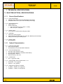
Table of Contents
SAFETY INSTRUCTIONS .................................................................................................................4
FCC INFORMATION ..........................................................................................................................5
VCCI ...................................................................................................................................................6
BRIEF DESCRIPTION .......................................................................................................................7
GENERAL ..........................................................................................................................................7
1. TECHNICAL SPECIFICATIONS ...............................................................................................8
1.1
ELECTRO-OPTICAL SPECIFICATIONS ............................................................................8
1.1.1
Screen Specifications .................................................................................................8
1.1.2
Optical Characteristics ...............................................................................................8
1.1.3
Input Signal Specifications .........................................................................................9
1.1.4
Controls of the Display .............................................................................................10
1.1.5
LED Indicator .............................................................................................................10
1.1.6
Power Supply Specification .....................................................................................10
1.1.7
Connectors .................................................................................................................10
1.1.8
Connection & PIN Assignment ................................................................................. 11
1.2
MECHANICAL SPECIFICATIONS ....................................................................................14
1.2.1
Dimension and Weight (Rack Mount ) .....................................................................14
1.2.2
Mounting.....................................................................................................................17
1.2.3
Finishing .....................................................................................................................17
1.2.4
Screws/Bolts ..............................................................................................................17
1.2.5
Components ...............................................................................................................17
1.2.6
Cooling .......................................................................................................................17
1.3
ENVIRONMENTAL SPECIFICATIONS .............................................................................17
1.3.1
Temperature ...............................................................................................................17
1.3.2
Humidity .....................................................................................................................17
1.3.3
Vibration .....................................................................................................................17
1.3.4
Altitude .......................................................................................................................18
1.3.5
EMC .............................................................................................................................18
1.3.6
Safety ..........................................................................................................................18
1.3.7
Certificate for ECDIS .................................................................................................18
1.3.8
Drip-proof ...................................................................................................................18
1.4
OHTER SPECIFICATIONS................................................................................................18
1.4.1
Reliability ....................................................................................................................18
1.4.2
Maintainability ............................................................................................................18
1.4.3
Use of toxic materials ...............................................................................................19
1.4.4
Packing .......................................................................................................................19
1.4.5
Buzzer Option. ...........................................................................................................19
2. Communication ......................................................................................................................20
2.1
Protocol ......................................................................................................................20
2.1.1
ASCII Characters Table .............................................................................................20
2.2.2
Communication Data Format ...................................................................................21
2.2.3
Commadns Table .......................................................................................................22
3
User Controls .........................................................................................................................26
3.1
Operation ..........................................................................................................................26
3.2
USER Control Access ......................................................................................................27
3.3
OSD(ON SCREEN DISPLAY) Navigation ........................................................................27
Revision Status
V2.2
Issued Date
2009-2-20
Page No.
Title
IDP2310UX
3 / 44
(AL23PUX)
3.3.1
3.3.2
3.3.3
3.3.4
Revision Status
V2.2
Adjustment .................................................................................................................28
COLOR ADJ ................................................................................................................31
PIP(Picture In Picture) ...............................................................................................34
SETUP MENU .............................................................................................................37
Issued Date
2009-2-20
Page No.
Title
IDP2310UX
4 / 44
(AL23PUX)
SAFETY INSTRUCTIONS
CAUTION
RISK OF ELECTRIC SHOCK
DO NOT OPEN
CAUTION: TO REDUCE THE RISK OF ELECTRIC SHOCK,
DO NOT REMOVE COVER (OR BACK).
NO USER-SERVICEABLE PARTS INSIDE.
REFER SERVICING TO QUALIFIED SERVICE PERSONNEL.
CAUTION: DOUBLE POLE / NEUTRAL FUSING.
DISCONNECT POWER BEFORE CHANGING FUSE.
Precautions
ON SAFETY
1. Before connecting the AC power cord to monitor, make sure the voltage designation of the monitor
corresponds to the local electrical supply..
2. Never insert anything metallic into the cabinet openings of the monitor; doing so may create the
danger of electric shock..
3. To avoid electric shock, never touch the inside of the monitor. Only a qualified technician should open
the case of the monitor.
4. Never use your monitor if the power cord has been damaged. Do not allow anything to rest on the
power cord, and keep the cord away from areas where people can trip over it.
5. Be sure to hold the plug, not the cord, when disconnecting the monitor from an electric socket.
6. Unplug your monitor when it is going to be left unused for an extended period of time.
7. Unplug your monitor from AC outlet before any service.
8. If your monitor does not operate normally - in particular, if there are any unusual sounds or smell
coming from it – unplug it immediately an authorized dealer or service center.
ON INSTALLATION
1. Openings and fans in the monitor cabinet are provided for ventilation. To prevent overheating, these
openings and fans should not be blocked or covered. Also avoid using the monitor on a bed, sofa rug,
or other soft surface, doing so may block the ventilation openings and fans in the monitor cabinet. If
you put the monitor in the enclosed space, be sure to provide adequate ventilation.
2. Put your monitor in a location with low humidity and minimum of dust.
3. Do not expose the monitor to rain or use it near water. If the monitor, accidentally, get wet, unplug it
and contact an authorized dealer immediately. You can clean the monitor with damp cloth if necessary,
but be sure to unplug the monitor first.
4. Place your monitor on a solid surface and treat it carefully.
5. Locate your monitor near an easily accessible AC outlet.
6. High temperature can cause problems. Do not use your monitor in direct sunlight and keep it away
from heater, stoves and other sources of heat.
ON CLEANING
The screen is made of thin glass with a plastic surface and can be damaged if dropped, hit and scratched.
Revision Status
V2.2
Issued Date
2009-2-20
Page No.
Title
IDP2310UX
5 / 44
(AL23PUX)
Do not clean the front panel with keton-type materials(e.g., acetone), ethyl alcohol, toluene, ethyl acid,
methyl or chloride – these may damage the panel.
ON REPACKING
Do not throw away the carton and packing materials. They make an ideal container which to transfer the
unit. If you have any questions about this unit, contact your authorized dealer.
ON DISPOSAL
This unit contains which can pollute the environment if disposed carelessly. Please contact our nearest
representative office or your local environmental office in case of disposal of this unit.
ON VESA MOUNTING
Make sure to unplug before installing this product. Otherwise, it may cause a fire or could give
an electric shock.
Do not install this product by yourself. Contact the qualified service technician. Otherwise, it may
cause injuries.
Do not install this product on the place where it cannot be supported. Otherwise, it may cause
the product to fall and could cause injuries.
Contact the qualified service technician for moving or replacing this product after installing.
Installing the product needs specified technique, so it may cause safety problem to move or
install it by yourself.
Do not hang on or impact on this product. Otherwise, it may cause the product to fall and could
cause injuries.
Do not install this product by alone. Get some help from others. Otherwise, it may cause the
product to fall and could cause injuries.
Do not place a heat source or a humidifier under the installed product. Otherwise, it may cause a
fire or could give an electric shock.
Do not install this product near a high voltage electric line, any power source or the place where
impact or vibration can affect.
Do not install this product barehanded. Otherwise, it may cause injuries.
The screw is not provided to user as default. Use the screw, which can stand the weight of this
product. And, we recommend the machine screw BH(+)M4 x 14mm to 18mm as type.
FCC INFORMATION
USER INSTRUCTIONS
The Federal Communications Commission Radio Frequency Interference Statement includes the
following warning:
NOTE
This equipment has been tested and found to comply with the limits for a Class A digital device,
pursuant to Part 15 of the FCC Rules. These limits are designed to provide reasonable
protection against harmful interference when the equipment is operated in a commercial
environment. This equipment generates, uses, and can radiate radio frequency energy and, if
not installed and used in accordance with the instruction manual, may cause harmful
interference to radio communications. Operation of this equipment in a residential area is likely
to cause harmful interference in which case the user will be required to correct the interference
at his own expense.
USER INFROMATION
Revision Status
V2.2
Issued Date
2009-2-20
Page No.
Title
IDP2310UX
6 / 44
(AL23PUX)
Changes or modifications not expressly approved by the party responsible for compliance could void the
user’s authority to operate the equipment.
If necessary, consult your dealer or an experienced radio/television technician for additional suggestions.
You may find the booklet called How to identify and Resolve Radio/TV Interference Problems helpful. This
booklet was prepared by the Federal Communications Commission. It is available from the U.S.
Government Printing Office, Washington, DC 20402, Stock Number 004-000-00345-4.
WARNING
User must shielded signal interface cables to maintain FCC compliance for the product.
DECLARATION OF CONFORMITY FOR PRODUCTS MARKED WITH FCC LOGO
This device complies with Part 15 of the FCC Rules. Operation is subject to the following two conditions:
(1) this device may not cause harmful interference, and (2) this device must accept any interference
received, including interference that may cause undesired operation.
This party responsible for product compliance:
Provided with this monitor is a detachable power supply cord with IEC320 style terminations. It may be
suitable for connection to any UL Listed personal computer with termination. Before making the
connection, make sure the voltage rating of the computer convenience outlet is the same as the monitor
and that the ampere rating of computer convenience outlet is equal to or exceeds the monitor voltage
rating.
For 120 Volt applications, use only UL Listed detachable power cord with NEMA configuration 5-15P type
(parallel blades) plug cap. For 240 Volt applications use only UL Listed detachable power supply cord
with NEMA configuration 6-15P type (tandem blades) plug cap.
VCCI
この裝置は、情報處理裝置等電波障害自主規制協議會(VCCI)の基準に基づくクラスA情報 この裝置は、情
報處理裝置等電波障害自主規制協議會(VCCI)の基準に基づくクラスA情報技術裝置です。 この裝置を家庭
環境で使用すると電波妨害を引き起こすことがあります。この場合には使用者が適切な對策を 講ずるよ
う要求されることがあります。
Revision Status
V2.2
Issued Date
2009-2-20
Page No.
Title
IDP2310UX
7 / 44
(AL23PUX)
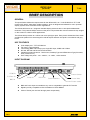
BRIEF DESCRIPTION
GENERAL
This specification defines the requirements for the IDP2310UX, 23.1” COLOR DISPLAY TFT LCD
monitor with 1600 X 1200 pixels visible resolution, which is designed and tailored for use in operator
display systems such as ECDIS monitor applications.
The IDP2310UX has a 23.1” diagonal viewable display area and 1600 x 1200 pixels addressable
resolution. The (0.098 X RGB) X 0.294 mm dot pitch LCD provides the most accurate and crisp images
on the screen for mission critical applications.
The IDP2310UX provides 16.7 million true colors (8-bit) per pixel. Each pixel is divided into Red, Green
and Blue sub pixels which are arranged in vertical stripes and each sub-pixel is controlled in 256 grey
levels.
KEY FEATURES
Color display 23.1” TFT LCD Monitor
Full 1600 x 1200 resolution
Two Analog (BNC and D-sub) input, single DVI input, CVBS and S-Video.
RS-422, RS-485 and RS-232 Communication
Versatile mechanical version : Rack mount, Desktop Type and VESA Mount Type(if it needs,
firstly contact for us)
Free Voltage AC power : 100 – 264Vac , 47 ~63Hz, 1.0A at 230Vac
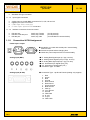
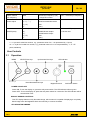
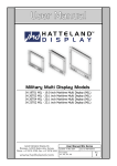
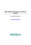
INPUT DIAGRAM
CVBS In
Power Switch
S-Video In
D-sub In
BNC In
DVI-D In
Serial Interface
Power Inlet
Power outlet
Revision Status
V2.2
BNC and D-sub input connectable to any source compatible to general CRT monitor
Digital input fully compatible to DVI-D Standard of VESA DDWG
Chain of Power just one level through power output totally
Issued Date
2009-2-20
Page No.
Title
IDP2310UX
8 / 44
(AL23PUX)
1. TECHNICAL SPECIFICATIONS
1.1 ELECTRO-OPTICAL SPECIFICATIONS
1.1.1
1.1.1.1
1.1.1.2
1.1.1.3
1.1.1.4
1.1.1.5
Screen Specifications
Panel Technologies
AMLCD (Active Matrix Liquid Crystal Display) technology
Amorphous silicon TFT (Thin Film Transistor) technology
Screen Dimensions
Aspect ratio 4:3
Active screen size:
470.4 (H) x352.8 (V) mm (18.52” x 13.89”)
588.0 mm (23.1”) diagonal
Display colors
16,777,216 true colors (8-bit), 256 grey scales
Resolution
1600 (H) x 1200 (V) pixels
Pixel arrangement: RGB (Red dot, Green dot, Blue dot) Vertical Stripe
Pixel pitch: 0.294 (W) x 0.294 (H) mm
Display mode
Normally Black
1.1.2
1.1.2.1
1.1.2.2
1.1.2.3
1.1.2.4
1.1.2.5
Optical Characteristics
Protective Filter Glass
Clear, tempered glass
Anti Reflective Film and Anti-Static Treatment
Luminance (Brightness)
250 cd/m² (max. typical on LCD)
240 cd/m² (max. typical on Protective Filter Glass)
Dimming Ratio: 1000 to 1
White uniformity: 75% max..
Contrast ratio
500 : 1 (typical on LCD)
Viewing Angle: At the contrast ratio > 10:1
Horizontal: +/- 85 (typical)
Vertical: +/- 85 (typical)
Response time @ 25C ambient
Tr (White Black): 10 ms (typical)
Td (Black White): 20 ms (typical)
Revision Status
V2.2
Issued Date
2009-2-20
Page No.
Title
IDP2310UX
9 / 44
(AL23PUX)
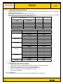
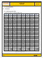
1.1.3
Input Signal Specifications
IDP2310UX provides maximum five (5) input signal interfaces, 2 x Analog (BNC,D-sub) Input ,1x Digital Input,
1xCVBS input and 1xS-video.
Standard input resolution is UXGA (1600 x 1200 pixels)
Other resolutions are supported as specified below. No scaling is provided for input signals with resolutions
less than the standard input resolution 1600x 1200 pixels.
Hsync
Vsync
Resolution
(KHz)
(Hz)
31.0 - 43.0
60.0 - 85.0
VGA
640 x 480
35.0 - 53.7
SVGA
800 x 600
56.0 - 85.0
48.4 - 68.3
60.0 - 85.0
XGA
1024 x 768
64.0 – 91.2
60.0 - 85.0
SXGA
1280 x 1024
UXGA(analog)
1600 x 1200
75.0 – 93.8
60.0 - 75.0
UXGA(digital)
1600 x 1200
75
60.0
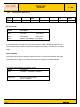
- Specified support resolutions
Resolution
1600x1200(digital)
1600x1200(analog)
1280x1024
1024x768
800x600
640x480
720x400
1.1.3.1
H-Frequency (kHz)/(polarity)
75(+)
93.75(+)
87.5(+)
81.25(+)
75(+)
91.146(+)
79.976(+)
63.981(+)
68.667(+)
60.023(+)
56.476(-)
48.363(-)
53.674(+)
46.875(+)
48.1(+)
37.879(+)
35.1(+)
43.269(-)
37.5(-)
37.7(-)
31.469(-)
31.469(-)
V-Frequency(Hz)/(polarity)
60(+)
75(+)
70(+)
65(+)
60(+)
85(+)
75(+)
60(+)
85(+)
75(+)
70(-)
60(-)
85(+)
75(+)
72(+)
60(+)
56(+)
85(-)
75(-)
72(-)
60(-)
70(+)
Analog Input
Analog RGB input signal shall be as follows:
Video Signal Level: 0.714 Vp-p nominal
Video Signal Polarity: Positive (Black to White). Polarity is detected automatically.
Both 0 V to +0.714 Vp-p and -0.714 V to 0 Vp-p is allowed.
Video Input Impedance: 75 Ohm terminated (RGB Video Signal)
Sync: TTL voltage levels, External Separate H & V Sync.
Interlace: Non-interlaced
1.1.3.2 Input Selection
In case multiple input source is connected, input to be displayed can be selected by:
Revision Status
V2.2
Issued Date
2009-2-20
Page No.
Title
IDP2310UX
10 / 44
(AL23PUX)
Manual: Operator can select the input manually using control panel.
1.1.4
1.1.4.1
1.1.4.2
Controls of the Display
Remote Control via serial ports (JH Communication compatible)
There are serial ports on the back side of the IDP2310UX for remote control of the monitor by customer
application.
RS-422 port:
Sub D, 15p, Female
(for JH protocol)
RS-232/485 port:
Sub D, 9p, Female
(for JH protocol)
RS-485 port:
Sub D, 9p, male as output (for Inter-Monitor Communication)
Control via OSD
Control block with the push buttons is available: Menu, Select, ◀ and ▶. Settings are selected by the Menu
that guides you through the OSD menu.
Control block also has Volume for dimming brightness.
Control block also has LED indicators, refer to 1.1.5.
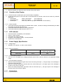
1.1.5
LED Indicator
Fault information in available by LED indicators
Normal : Green indicator
Soft Power Off: Amber indicator
No signal : Amber Blinking (every 1 second) indicator
System Fault : Red indicator
1.1.6
1.1.6.1
1.1.6.2
Power Supply Specification
Voltage range
Standard :100 –264Vac, 47~63Hz,1.0A at 230Vac
Power consumption
Normal
Max.
(100% Light output)
IDP2310UX
1.1.6.3
1.1.6.4
90W
Power variation protection
Unit will not be damaged when Voltage transients remain within value as defined in the applicable voltage
range
Over-temperature protection
When the internal temperature gets above than the warning level (65℃), the light output of the backlight is
half. And, LED as red color
When the internal temperature reaches above the critical Value (80℃), the light output of the backlight is
turned off. And, LED as red color
When the internal temperature gets below than the safe level (64℃), the light output of the backlight is
restored. And, LED recovers to green.
1.1.7
Connectors
1.1.7.1
Power connectors
Revision Status
V2.2
80 W
Issued Date
2009-2-20
Page No.
Title
IDP2310UX
11 / 44
(AL23PUX)
Standard: IEC type connector
1.1.7.2
Input signal connectors
Analog Input: 5 Coaxial BNC connectors for R, G, B, HS and VS
Digital input: DVI-D connectors
CVBS input: RCA connectors
S-video input: 4pin mini DIN connectors
1.1.7.3
Interface connectors for remote control
RS-422 port:
RS-232 or RS-485 port:
RS-485 port:
1.1.8
Sub D, 9p, Female
Sub D, 9p, Female
Sub D, 9p, male
(for JH protocol)
(for JH protocol)
(for Inter-Monitor communication)
Connection & PIN Assignment
Power Input / output
● 90-264Vac, 47~63Hz with double pole / neutral fusing,
250V F3.15AL
● Disconnect power before changing fuse
● Chain thru power output to limit to one level totally
Analog Input (BNC)
●
●
●
●
●
●
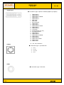
Analog Input (D-Sub)
● Connection Type : 15p D-aub Female (Analog only support)
R : Analog Red Signal Input (0.7 Vpp, 75 ohm)
G : Analog Green Signal Input (0.7 Vpp, 75 ohm)
B : Analog Blue Signal Input (0.7 Vpp, 75 ohm)
HS : Horizontal Sync Signal Input (TTL)
VS : Vertical Sync Signal Input (TTL)
Connection Type : 5 x BNC
1.
2.
3.
4.
5.
6.
7.
8.
9.
10.
11.
12.
13.
14.
15.
Revision Status
V2.2
Red
Green
Blue
Ground
DDC Ground
Red Ground
Green Ground
Blue Ground
back up
sync Ground
Ground
DDC Data
H sync
V sync
DDC Clock
Issued Date
2009-2-20
Page No.
Title
IDP2310UX
12 / 44
(AL23PUX)
Digital Input
● Connection Type : 29p DVI-I Female (Digital only support)
1.
2.
3.
4.
5.
6.
7.
8.
9.
10.
11.
12.
13.
14.
15.
16.
17.
18.
19.
20.
21.
22.
23.
24.
S-Video
TMDS Data 2TMDS Data 2+
TMDS Data 2/4 Shield
TMDS Data 4TMDS Data 4+
DDC Clock
DDC Data
No Connection
TMDS Data 1TMDS Data 1+
TMDS Data1/3 Shield
TMDS Data 3TMDS Data 3+
+5V power
Ground (Return for +5V)
Hot Plug Detection
TMDS Data 0TMDS Data 0+
TMDS Data 0/5 Shield
TMDS Data 5TMDS Data 5+
TMDS Clock Shield
TMDS Clock+
TMDS Clock-
C1 ~ C5 : No Connection
● Connection Type : 4-pin DIN Jack
1.
2.
3.
4.
GND
LUMA
CROMA
GND
CVBS
● Connection Type : RCA Jack
Revision Status
V2.2
Issued Date
2009-2-20
Page No.
Title
IDP2310UX
13 / 44
(AL23PUX)
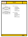
Serial Interface
● Remote In(female)
1.
2.
3.
4.
5.
6.
7.
8.
9.
No connection
RxD (for RS-232)
TxD (for RS-232)
TxIN_B (for RS-485)
RxIN_B (for RS-485)
No connection
Ground
TxIN_A (for RS-485)
RxIN_A (for RS-485)
● Remote out(male)
1. No connection
2. No connection
3. No connection
4. TxOUT_B (for RS-485)
5. RxOUT_B (for RS-485)
6. No connection
7. Ground
8. TxOUT_A (for RS-485)
9. RxOUT_A (for RS-485)
Revision Status
V2.2
Issued Date
2009-2-20
Page No.
Title
IDP2310UX
14 / 44
(AL23PUX)
1.2 MECHANICAL SPECIFICATIONS
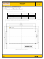
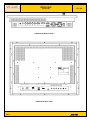
1.2.1 Dimension and Weight (Rack Mount )
The dimension of the unit is as shown in the table below:
Monitor only
Packing
Height (mm / inch)
534 / 21.02
780/ 30.71
Width (mm / inch)
584 / 22.99
790/ 31.10
Depth (mm / inch)
93.8 / 3.69
297.5/ 11.72
Weight (kg / lbs)
15.5 / 34.2
20.5 / 45.2
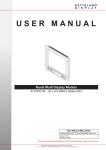
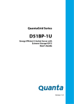
The following figures show a Rack Mount version mechanical dimension. IDP2310UX basically provides three
input connectors and all connectors are located the bottom side of monitor.
< IDP2310UX Front View : unit mm >
Revision Status
V2.2
Issued Date
2009-2-20
Page No.
Title
IDP2310UX
15 / 44
(AL23PUX)
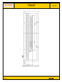
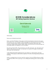
< IDP2310UX Bottom View >
< IDP2310UX Rear View >
Revision Status
V2.2
Issued Date
2009-2-20
Page No.
Title
IDP2310UX
16 / 44
(AL23PUX)
< IDP2310UX Side View : unit mm>
Revision Status
V2.2
Issued Date
2009-2-20
Page No.
Title
IDP2310UX
17 / 44
(AL23PUX)
1.2.2 Mounting
The weight for the unit shall not exceed 15.5 kg (34.2 lbs)
Fixing: using 4 captive M6 bolts in front bezel
IDP2310UX can be Standard rack mounted with an optional adapter plate
1.2.3 Finishing
Standard Bezel color is Black (Rack Mount Type)
Other bezel colors can be made available on request
1.2.4 Screws/Bolts
Number of screws to use for maintenance: reduced to minimum
Type of screws requires maximum 3 standard tools
1.2.5 Components
Industrial extended temperature range components are used for cost, maintainability and reproducibility
purposes.
1.2.6 Cooling
The Unit does not need any forced air-cooling
1.3 ENVIRONMENTAL SPECIFICATIONS
The unit is designed to meet the following environmental standards:
1.3.1 Temperature
Operating : -15C ~ + 55C (+5F ~ +131F)
Storage : - 40C ~ + 70C (-40F ~ + 158F)
IEC60945
Note: The unit may show limited performance in case of continuous operation at low temperature due to the
increased response time and reduced brightness, and may not confirm to the requirements of this
specification.
1.3.2 Humidity
Operating: 10% - 90%
Storage: 5% - 95%
IEC60945
1.3.3 Vibration
Revision Status
V2.2
1.03 Grms for 5 ~ 200Hz Random Vibration
1 hour (Z : 30 min, X,Y : 15 min, respectively)
Chassis Type with packing in carton box
IEC60945
Issued Date
2009-2-20
Page No.
Title
IDP2310UX
18 / 44
(AL23PUX)
1.3.4 Altitude
Non-operating
Operating
: Up to 30,000 ft
: Up to 10,000 ft
1.3.5 EMC
FCC Part 15 subpart B, Class A
CE(EMC)
-EN55022(EMI)
-EN55024(EMS)
MIC
VCCI Class A
IEC60945
1.3.6 Safety
CE & CB
EN60950-1
UL / cUL
UL60950-1
1.3.7 Certificate for ECDIS
EN61174(IEC61174)
1.3.8 Drip-proof
Front side is drip-proof. Test shall be done when the unit is mounted in a console.
Front bezel: IP64
NOTE: The unit is type approved according to EN60945(2002),4.4, equipment category b)Protected from the
weather (formerly class B)
1.4 OHTER SPECIFICATIONS
1.4.1 Reliability
MTBF (Mean Time Between Failures)
Standard calculated MTBF : 40,986h (MIL-HDBK-217F)
Ship calculated MTBF : 19,468h (MIL-HDBK-217F)
1.4.2 Maintainability
MTTR (Mean Time Between Repair)
IDP2310UX is defined as a Line Replaceable Unit (LRU) and the unit is designed to allow for an MTTR
less than 0.5 hour (30 minutes).
Revision Status
V2.2
Issued Date
2009-2-20
Page No.
Title
IDP2310UX
19 / 44
(AL23PUX)
Use of maintenance equipment
A modular design is taken for the unit. No special tools or equipment are required for maintenance
purpose.
1.4.3 Use of toxic materials
Cold Cathode Fluorescent Lamp (CCFL) in the backlight assemblies contains a small amount of mercury. The
backlight assembly is placed inside of the monitor and is not exposed to user.
1.4.4 Packing
The unit shall be packaged for international transport by air freight in accordance with best practices for insuring
arrival at customer site in an undamaged condition.
1.4.5 Buzzer Option.
Revision Status
V2.2
Issued Date
2009-2-20
Page No.
Title
IDP2310UX
20 / 44
(AL23PUX)
2. Communication
2.1
Protocol
2.1.1 ASCII Characters Table
:
All communications are based on ASCII Code.
ASCII
ASCII
ASCII
Char.
Char.
Code
Code
Code
Char.
ASCII
Code
Char.
0x00
NULL
0x20
SP
0x40
@
0x60
`
0x01
SOH
0x21
!
0x41
A
0x61
a
0x02
STX
0x22
"
0x42
B
0x62
b
0x03
ETX
0x23
#
0x43
C
0x63
c
0x04
EOT
0x24
$
0x44
D
0x64
d
0x05
ENQ
0x25
%
0x45
E
0x65
e
0x06
ACK
0x26
&
0x46
F
0x66
f
0x07
BELL
0x27
'
0x47
G
0x67
g
0x08
BS
0x28
(
0x48
H
0x68
h
0x09
HT
0x29
)
0x49
I
0x69
i
0x0a
LF
0x2a
*
0x4a
J
0x6a
j
0x0b
VT
0x2b
+
0x4b
K
0x6b
k
0x0c
FF
0x2c
,
0x4c
L
0x6c
l
0x0d
CR
0x2d
-
0x4d
M
0x6d
m
0x0e
SO
0x2e
.
0x4e
N
0x6e
n
0x0f
SI
0x2f
/
0x4f
O
0x6f
o
0x10
DLE
0x30
0
0x50
P
0x70
p
0x11
DC1
0x31
1
0x51
Q
0x71
q
0x12
DC2
0x32
2
0x52
R
0x72
r
0x13
DC3
0x33
3
0x53
S
0x73
s
0x14
DC4
0x34
4
0x54
T
0x74
t
0x15
NAK
0x35
5
0x55
U
0x75
u
0x16
SYN
0x36
6
0x56
V
0x76
v
0x17
ETB
0x37
7
0x57
W
0x77
w
0x18
CAN
0x38
8
0x58
X
0x78
x
0x19
EM
0x39
9
0x59
Y
0x79
y
0x1a
SUB
0x3a
:
0x5a
Z
0x7a
z
0x1b
ESC
0x3b
;
0x5b
[
0x7b
{
0x1c
FS
0x3c
<
0x5c
\
0x7c
|
0x1d
GS
0x3d
=
0x5d
]
0x7d
}
0x1e
RS
0x3e
>
0x5e
^
0x7e
~
0x1f
US
0x3f
?
0x5f
_
0x7f
DEL
– End of ASCII Characters Table –
Revision Status
V2.2
Issued Date
2009-2-20
Page No.
Title
IDP2310UX
21 / 44
(AL23PUX)
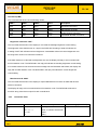
2.2.2
Byte#
Communication Data Format
0
1
2,3,4
5
6
7,ect
7+LEN
ATTN
ADDR
CMD
LEN
IHCHK
DATA
IDCHK
Attention (ATTN)
This byte is used to identify a start of message. It can be one of 3 values:
ATTN
Description
0x07
Command
(ASCII BELL)
0x06
Acknowledge
(ASCII ACK)
0x15
Negative Acknowledge (ASCII NAK)
A device shall send a command using the 0x07 Attention Code. The display will respond to the
Command with either an ACK if the command completed successfully, or a NAK if the command
failed.
Address (ADDR)
This byte is used to specify a particular display to receive a command and to identify the display
responding (ACK or NAK) to a command. All displays will support the broadcast address.
The display will meet all functional requirements without individual Display addressing
The Address field shall have the following values:
ADDR
Description
0xFF
Broadcast – Addressed to all display
0x00 to 0x0f
Address of a specific display
(max of 16 Display)
Revision Status
V2.2
Issued Date
2009-2-20
Page No.
Title
IDP2310UX
22 / 44
(AL23PUX)
Command (CMD)
The command shall be one of the following values:
CMD 0
CMD1
CMD2
ASCII
Description
0x42
0x52
0x54
“BRT”
Brightness Command
0x4D
0x41
0x4E
“MAN”
Manufacturer ID Code
0x4D
0x43
0x43
“MCC”
Display Control Command
0x54
0x59
0x50
“TYP”
Type/Model Number Command
Brightness Command “BRT”
This command shall be sent to the display to command the backlight brightness control setting.
The brightness value shall be sent as 1 byte in the DATA field. A setting of 0x00 will indicate off.
A setting of 0xFF will indicate maximum brightness. Intermediate values will control brightness over
the range from minimum to maximum luminance.
If the data checksum is valid and the brightness was set, the display will reply to this command with
an ACK attention code. The DATA field in the reply will indicate the resulting brightness control setting.
If an invalid checksum was received and the message was not Broadcast and RS485, the display will
reply with an NAK attention code. The DATA field in the reply will indicate the current brightness
control setting.
Manufacturer ID “MAN”
This command shall be sent to the display to request Manufacturer ID Code. No data shall be sent
with this command.
The display will reply to this command with an ACK attention code. The DATA field will be set to
an ASCII string value that is unique for each manufacturer.
2.2.3
Commadns Table
function
Brightness control
Revision Status
V2.2
Command
Description
0x81,
Set brightness =
nn l “+” l ”-“ l
Value / increment / decrement
“r” l “R” l
Reset
“?”
Query
Acknowledge (if enabled)
Brightness.
Issued Date
2009-2-20
Page No.
Title
IDP2310UX
23 / 44
(AL23PUX)
Contrast control-
0x82, ”a” l “A”,
Set all contrast =
all channels
nn l “+” l “-“ l
Value / increment / decrement
“r” l “R”
Reset
“?”
Query
Color temperature
0xb3,
Select color temperature =
Main selected
select
nl
Value
“0”-9200K.
“r” l “R” l
Reset
“1”-6400K.
“?”
Query
“2”-5600K.
0xb4,
Set the level of the red
Red level for selected color
channel
temperature
Red level for selected
Color temperature
nn l ”+” l “-“ l
“r” l “R” l
“?”
Contrast
for the selected color temp. =
Value
/
increment
/
decrement
Reset
Query
Green
level
for
0xb5,
selected
Color temperature
Set the level of the green
Green level for selected color
channel
temperature
nn l ”+” l “-“ l
for the selected color temp. =
“r” l “R” l
Value / increment / decrement
“?”
Reset
Query
bule
level
for
0xb6,
selected
Color temperature
Set the level of the Bule
Bule level for selected color
channel
temperature
nn l ”+” l “-“ l
for the selected color temp. =
“r” l “R” l
Value / increment / decrement
“?”
Reset
Query
Clock ( frequency )
0x8b
Set H active size =
Graphic mode H active size
(Analog , bnc only)
nnn l “+” l “-“ l
Value / increment / decrement
(in pixels)
“r” l “R” l
Reset
“?”
Query
Phase
0x85
Set dot clock phase =
(Analog , bnc only)
nnn l “+” l “-“ l
Value / increment / decrement
“r” l “R” l
Reset
“?”
Query
0xbb
Status of OSD
OSD status enquiry
dot clock phase
“0”-OSD turned off
“1”-OSD turned off
H position
Revision Status
V2.2
0x86,
Set H position
nnn l “+” l “-“ l
Value / increment / decrement
“r” l “R” l
Reset
“?”
Query
Horizontal position
Issued Date
2009-2-20
Page No.
Title
IDP2310UX
24 / 44
(AL23PUX)
V position
0x87,
Set H position
nnn l “+” l “-“ l
Value / increment / decrement
“r” l “R” l
Reset
“?”
Query
PIP window size
0xa6,
Select PIP window size =
PIP window size selected
Select
nl
PIP window size value
“0”-small size
“r” l “R” l
Reset
“1”-large size
“?”
Query
0xa7,
Select input main =
Main selected.
nl
Video source value
“0”-CVBS
“r” l “R” l
Reset
“1”-S-video
“?”
Query
0xa4,
Select location =
Select ed PIP location
nl
PIP location value
“0”-left top
“r” l “R” l
Reset
“1”-right top
“?”
Query
“2”-right bottom
PIP source select
PIP Location
vertical position
“3”-left bottom
PIP ON / OFF
0xa5,
Select PIP ON /OFF =
Select ed PIP location
nl
PIP ON / OFF value
“0”-PIP turned off
“r” l “R” l
Reset
“1”-PIP turned on
“?”
Query
Video brightness
0x84,
Set video brightness =
control
nn l “+” l “-“ l
Value / increment / decrement
(CVBS,S-video only)
“r” l “R” l
Reset
“?”
Query
Video contrast
0x83,
Set video contrast =
control
nn l “+” l “-“ l
Value / increment / decrement
(CVBS,S-video only)
“r” l “R” l
Reset
“?”
Query
Graphic mode
0x89,
Set graphic mode sharpness
sharpness
nnn l “+” l “-“ l
=
(Analog, BNC only)
“r” l “R” l
Value / increment / decrement
“?”
Reset
video brightness
video contrast
Graphic mode sharpness
Query
Video sharpness
0x8a,
Set video mode sharpness =
(CVBS,S-video only)
nnn l “+” l “-“ l
Value / increment / decrement
“r” l “R” l
Reset
“?”
Query
Select OSD
0x95,
Select language =
“0”-English
language
nl
English, Korea
“1”-Korea
“r” l “R” l
Reset
Revision Status
V2.2
video mode sharpness
Issued Date
2009-2-20
Page No.
Title
IDP2310UX
25 / 44
(AL23PUX)
Input main select
“?”
Query
0x98,
Select input main =
Main selected
n l “+” l “-“ l
PC or VIDEO or next available
“0”-Analog RGB(PC)
“r” l “R” l
Reset
“1”-Digital DVI(PC)
“?”
Query
“2”-BNC(PC)
“3”-CVBS
“4”-S_video
Select menu timeout
0x93,
Select menu timeout =
OSD menu timeout selected
n l “+” l “-“ l
Value / increment / decrement
“0”-20s
“r” l “R” l
Reset
“1”-30s
“?”
Query
“2”-50s
“3”-100s
OSD H position
OSD H position
Soft Power On / Off
Query information
0x90,
Set OSD H position
OSD Horizontal position
nnn l “+” l “-“ l
Value / increment / decrement
“r” l “R” l
Reset
“?”
Query
0x91,
Set OSD H position
nnn l “+” l “-“ l
Value / increment / decrement
“r” l “R” l
Reset
“?”
Query
0xc8
Soft power
“0”-soft power off
“0” l “1” l
Off/on
“1”-soft power on
“?”
Query
0xc9
read the status of information
OSD Horizontal position
“0”-serial number
“1”-s/w ver
status
“2”-temperature value
“3”-input satus
“4”-communication
“5”-backlight value
Query PCBA
0xcb, “1”
Read PCBA number
“nnnn” = PCBA number
0xce
Reset all parameters to default
“1”-successful
number
Factory Recall
Value.
Graphic horizontal
0xb7
Resolution enquiry
Horizontal
resolution
(in
“nnn” = Horizontal resolution
pixels)
In 3 digit hex number
Graphic Vertical
0xb8
Resolution enquiry
Graphic horizontal
Sync frequency
Vertical resolution (in lines)
“nnn” = Vertical resolution
In 3 digit hex number
0xb9
Horizontal
Sync
frequency
(KHz)
“nnn”
=
Horizontal
frequency
In 3 digit hex number
Revision Status
V2.2
Issued Date
2009-2-20
Sync
Page No.
Title
IDP2310UX
26 / 44
(AL23PUX)
Graphic Vertical
0xba
Sync frequency
Vertical Sync frequency (Hz)
“nnn” = Vertical Sync frequency
In 3 digit hex number
Buzzer control-
0x80,”a” | ”A”,
Set Buzzer Volume =
Volume adjust
n | “+” | “ - ”|
Value/increment/decrement
“r” | “R”|
Rest
“?”
Query
Buzzer control-
0x80,”m” | ”M”,
ON/OFF(mute)
“0” |
Disable Buzzer Output
“1” |
Enable Buzzer Output
“r” | “R”|
Rest
“?”
Query
Buzzer Volume Control
“0” Buzzer OFF(mute)
“1” Buzzer ON.
n = 1- byte ascii-coded hex number, e.g., parameter value of 0 x 1 is represented by “1”(0x31)
nn = 2 – byte ascii coded hex number, e.g., parameter value of 0 x 1e is represented by “1”,”e” l ”E”
(0x31,0x6el0x4e)
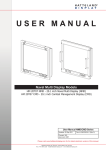
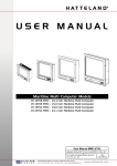
3 User Controls
3.1
Operation
MENU
Hot Key4
SELECT/Hot Key1
Up/Increase /Hot Key3
Down/Decrease/Hot Key2
LED indicator
Brightness Knob
Soft Power Switch
POWER ON AND OFF
Power ON: To turn the display on, press the soft-power switch. The LED indicator will turn green.
Power OFF: To turn the display off, press the soft power switch for 5 seconds. The LED indicator will be
turned Amber color.
DISPLAY DIMMING CONTROLS
This TFT display features a fully dimmable image, which means it is capable of displaying a completely
Black image when the Brightness Knob is turned fully to counter-clockwise.
LED INDICATOR DIMMING
Revision Status
V2.2
Issued Date
2009-2-20
Page No.
Title
IDP2310UX
27 / 44
(AL23PUX)
The LED light intensity is adjusted with the backlight Knob.
HOT KEY
The user can assign various display function as hot keys
Hot Key1 is able to directly source change. Press the “SELECT”.
Hot Key2 is able to directly PIP. Press and hold the “◀” for 5seconds
Hot Key3 is able to directly auto adjustment in Analog. Press the “▶” for 5 seconds.
When auto adjustment is preformed on the special pattern, if it needs, firstly contact for us.
Hot Key4 is able to protect directly OSD. Press and hold the “MENU and SELECT” for 5 second
simultaneously.
3.2
USER Control Access
1: Press the ”MENU” button. The OSD menu will show all the available functions you can
adjust or control.
2: You can move to the next icon by pressing “◀ and ▶”.
3: Select options within icon menu by pressing “SELECT” button. The select option will turn yellow.
4: Use “◀” or “▶” button to decrease/increase values.
5: Move the selection left or right by using “◀” or “▶” button. The selected option will turn blue bar.
6: You can exit the pressing “MENU”.
3.3
OSD(ON SCREEN DISPLAY) Navigation
The description below is how to operate the control functions via OSD. The following is the initial OSD menu
displayed by pressing “MENU”. It looks like the general computer monitor, so it is more users friendly.
Revision Status
V2.2
Issued Date
2009-2-20
Page No.
Title
IDP2310UX
28 / 44
(AL23PUX)
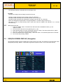
3.3.1 Adjustment
The “Adjustment” menu is for controlling the brightness, contrast, positions, sharpness, clock and phase.
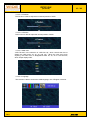
3.3.1.1 BRIGHTNESS
The function is able the user to adjust brightness for the display, 50 is default value.
“Brightness” adjusts the light output by controlling the opening of Liquid Crystal, it is different from “Dim
Brightness” which is adjusted by controlling the amount of light of backlight directly. But their effects are
very similar. Its adjustment range is -127 to +127. The closer to -127 it is, the darker it is and the closer
to +127 it is, the brighter it is. When one of the submenu of “Adjustment” is selected, the select button
push to select it., so that adjusts the values of the brightness. When the menu button is pushed , going
back to the upper menu.
To adjust the brightness is to remap the input data to output data in terms of black and white level. It is
to change the range of data, it means that if the brightness is 127, input data 0 - 255 is remapped to
output data 127 – 255, so it looks like brighter. On the other way, if the input data is remapped to 0 –
127, it’ll be darker. It is to remap the data to LCD panel newly, but it is not to change the real input data.
The brightness adjustment acts on the displayed image of all input data - R, G, and B by the same
level.
Revision Status
V2.2
Issued Date
2009-2-20
Page No.
Title
IDP2310UX
29 / 44
(AL23PUX)
3.3.1.2 CONTRAST
The function is able the user to adjust contrast for the display, 50 is default value.
“Contrast” is the submenu of “Adjustment”, which sets up the gain of output video signal to panel. Its
adjustment range is 0 to +100. When one of the submenus of “Adjustment” selected, the select
button push to select it. so that adjust the values of the Contrast. When the menu button pushed,
going to the upper menu.
To adjust the contrast is to remap the input data to the output data in terms of white level only. It
means that if the contrast is max. 100, input data over 127 is mapped to 255, so, the depth between
black and white is expanded. On the other way, if it is min. 0, input data 0 – 255 is mapped to 0 –
127, so, the depth is reduced. The contrast adjustment acts on the displayed image of all input data R, G, and B by the same level. And it also controls the data to panel, but it does not adjust the input
i
l
3.3.1.3 H.POSITION
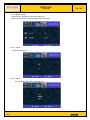
The function is able the user to adjust horizontal position of image
“H-Position” is the submenu of “Adjustment”, which controls the horizontal position of image, Its
adjustment range is 0 to +100 and default is 50. When the H-position of the submenu of
“Adjustment” is selected, the select button push to select it. so that adjust the values of the
H-position. When the encoder switch pushed , going to the upper menu.
Adjusting the “H-position” shifts the horizontal position of image. If the value of “H-position” is
increased or decreased by pressing “◀ and ▶”, the “H-position” shifts to the right or to the left.
Revision Status
V2.2
Issued Date
2009-2-20
Page No.
Title
IDP2310UX
30 / 44
(AL23PUX)
3.3.1.4 V.POSITION
The function is able the user to adjust vertical position of the display.
“V-Position” is the submenu of “Adjustment”, which controls the vertical position of image, Its
adjustment range is 0 to +100 and default is 50. When the V-position of the submenu of “Analog
adjustment” is selected, the select button push to select it. so that adjust the values of the
V-position. When the encoder switch pushed , going to the upper menu.
Adjusting the V-position shifts the vertical position of image. If the value of “V-position” is
increased or decreased by pressing “◀ and ▶”, the “V-position” shifts the upper or the lower.
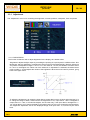
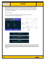
3.3.1.5 SHARPNESS
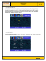
The function is able the user to adjust sharpness for the display
Closer to 0
Original
Closer to 100
“Sharpness” is for making a clear image. Its adjustment range is 0 to +100. When it is 100, the
image is the most clear. When it is closer to 0, the image is blurred. This is not the absolute value
on all signals. It may differ from every signal because the original source quality is very various. If
the original signal is good quality, the image may be looked rather artificially than clearly in max.
value 100. In this time, the value should be adjusted to lower value. If the original source is poor
quality, the image becomes clearly more by adjusting closer to 100. The default value is 50.
Revision Status
V2.2
Issued Date
2009-2-20
Page No.
Title
IDP2310UX
31 / 44
(AL23PUX)
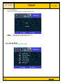
3.3.1.6 CLOCK
The function is able the user to adjust the number of sampling clock.
The “Clock” is the menu for the setting of the number of pixels corresponding to the pixel rate of
the applied analog input signal. It represents the number of sampling clock during one period of
horizontal sync signal.
3.3.1.7 PHASE
The function is able the user to adjust phase of sampling clock
Its range is 0˚ to 360˚ , which is adjusted by 5.625˚ per one step and can be totally adjusted to
64 steps. This is not represented on OSD by a real phase value, but it is represented by 0 to 100 on
OSD.
3.3.2 COLOR ADJ
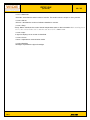
The “COLORADJ” menu is for controlling the Color Temperature, RGB ADJ and Black.
Revision Status
V2.2
Issued Date
2009-2-20
Page No.
Title
IDP2310UX
32 / 44
(AL23PUX)
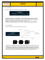
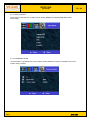
3.3.2.1 COLOR TEMPERATURE
The function is able the user to modify the color temperature of the picture for the Display.
Higher temperature : “cooler” picture. Lower temperature : “warmer” picture.
User can select one of 9200K, 6400K, 5600K and User color temperature measured
You can adjust color temperature via the User(RGB)
3.3.2.2 RGB ADJ
The function is able the user to adjust Red, Green and Blue offset for the display
These set up the gain of black level of input video signal to ADC amp (Analog to Digital Converter).
.
Revision Status
V2.2
Issued Date
2009-2-20
Page No.
Title
IDP2310UX
33 / 44
(AL23PUX)
When all white levels are on the points of OSD 50, the amount of color is the same each other.
But, if the level is moved closed to OSD 100, the amount of color to adjust is more, so, the color
to adjust looks like strong. On the other way, if it goes to OSD 0, the amount of color to adjust is
less, so, the color is felt weakly. If the color is changed in brighter level, adjust the white level.
But it also effects on dark level.
3.3.2.3 BLACK LEVEL
The function is able the user to adjust Red, Green and Blue gain for the display
These set up the offset of video signal of ADC amp.
When all black levels are on the points of OSD 50, the amount of color is the same each other. But,
if the level is moved closed to OSD 100, the amount of color to adjust is more, so, the color to adjust
looks like strong. On the other way, if it goes to OSD 0, the amount of color to adjust is less, so, the
color is felt weakly. If the color is changed in darker level, adjust the black level. But it also effects on
bright level.
Revision Status
V2.2
Issued Date
2009-2-20
Page No.
Title
IDP2310UX
34 / 44
(AL23PUX)
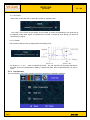
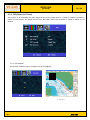
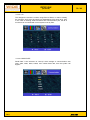
3.3.3 PIP(Picture In Picture)
This function is for displaying the video image window on the image from PC. CVBS or S-Video is possible to
display on PIP window. The image from PC over DVI, BNC and D sub connector is unable to display on the
window.
3.3.3.1 PIP ON/OFF
This function is able the user to configure PIP window ON/OFF
< PIP ON >
Revision Status
V2.2
Issued Date
2009-2-20
Page No.
Title
IDP2310UX
35 / 44
(AL23PUX)
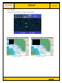
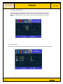
3.3.3.2 PIP SIZE
This function is able the user to configure PIP window size.
<PIP Size: Small>
Revision Status
V2.2
<PIP Size: Large>
Issued Date
2009-2-20
Page No.
Title
IDP2310UX
36 / 44
(AL23PUX)
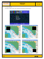
3.3.3.3 PIP LOCATE
The function is able the user to the configure PIP horizontal and vertical position
Revision Status
V2.2
<Left Top>
<Right Top>
<Left Bottom>
<Right Bottom>
Issued Date
2009-2-20
Page No.
Title
IDP2310UX
37 / 44
(AL23PUX)
3.3.3.4 PIP SOURCE
The function is able the user to configure PIP input source.
CVBS
= manual select composite video signal only
SVIDEO = manual select S-Video signal only.
3.3.4 SETUP MENU
In this menu, user can set up the setting values.
Revision Status
V2.2
Issued Date
2009-2-20
Page No.
Title
IDP2310UX
38 / 44
(AL23PUX)
3.3.4.1 INPUT SELECT
The function is able the user to select one of Analog RGB(D-sub), Digital RGB, BNC,CVBS
and S-Video
3.3.4.2 COMMUNICATION
“Communication” represents the communication setting between monitors or between the control
system and the monitor
Revision Status
V2.2
Issued Date
2009-2-20
Page No.
Title
IDP2310UX
39 / 44
(AL23PUX)
3.3.4.2.1 ID
This assigns the monitor’s number, range Zero to fifteen, in order to identify
the monitors, and it must be unique for distinguishing from each other. And,
In the case of chaining several monitors thru communication port, the ID of
monitor to be connected with control system must by Zero.
3.3.4.2.2 BAUD RATE
“Baud Rate” is the submenu of “Set-Up” which assigns a communication rate,
1200, 2400, 4800, 9600, 57600, and 115200 baud rate, that the system can
support.
Revision Status
V2.2
Issued Date
2009-2-20
Page No.
Title
IDP2310UX
40 / 44
(AL23PUX)
3.3.4.2.3 Communication
This assigns the communication mode. The monitor connecting with the control
system is assigned the RS232 or RS422 and it connecting with other monitor is
assigned to the RS485. So, one of three must be chosen as input communication
mode.
3.3.4.3 OSD SETUP
“OSD Set Up” is the submenu of “Set-Up” which sets up the position of OSD, and OSD Timeout.
Revision Status
V2.2
Issued Date
2009-2-20
Page No.
Title
IDP2310UX
41 / 44
(AL23PUX)
3.3.4.3.1 H.Position
This function is able to adjust the horizontal position of OSD.
3.3.4.3.2 V.Position
This function is able to adjust the vertical position of OSD.
3.3.4.3.3 TIME OUT
“OSD Timeout” is the submenu of “OSD Set Up”, which controls the time to
display the OSD menu 20, 30, 50, and 100 : When the user don’t touch
anything, the OSD menu is disappeared after 20, 30, 50 or 100 seconds,
which keeps display OSD.
3.3.4.3.4 Language
This function is able to choose the OSD language, one of English or Korean.
Revision Status
V2.2
Issued Date
2009-2-20
Page No.
Title
IDP2310UX
42 / 44
(AL23PUX)
3.3.4.4 Buzzer Set Up.
This function is available to the buzzer model only
This function is buzzer on/off and adjusts volume controls.
3.3.4.4.1 On/Off
Buzzer On/Off control
3.3.4.4.2 Volume
The sound adjust the ‘low, middle and high’
Revision Status
V2.2
Issued Date
2009-2-20
Page No.
Title
IDP2310UX
43 / 44
(AL23PUX)
3.3.4.5 FACTORY RECALL
“Factory Recall” is the menu for restoring to the factory setting values. The settings with which
the display leaves factory are stored in a factory settings storage area on main control board.
And the current settings are stored in a user settings storage area on main control board. At
administrator level, the current settings are replaced by the factory settings. The user settings
disappear after changing by the factory settings.
3.3.4.6 INFOMATION
This function describes the Serial Number, S/W version, Temperature, input source, communication
Mode and the light of Backlight.
Revision Status
V2.2
Issued Date
2009-2-20
Page No.
Title
IDP2310UX
44 / 44
(AL23PUX)
3.3.4.6.1 Serial NO.
“Serial No.” describes the serial number of monitor. The serial number is unique on every monitor.
3.3.4.6.2 SW ver.
“S/W ver.” describes the version of software installed on monitor.
3.3.4.6.3 Temp.
“Temp. Status” describes the current internal temperature status or the information of the warning level
(65℃), the critical Value (80℃) and the safe level (64℃). See 1.1.6.4.
3.3.4.6.4 Input
A signal to display now on screen is described.
3.3.4.6.5 Comm.
“Comm.” represents a communication mode.
3.3.4.6.6 Backlight
“Backlight” represents the light of backlight.
Revision Status
V2.2
Issued Date
2009-2-20