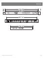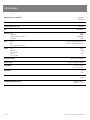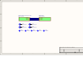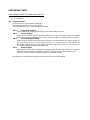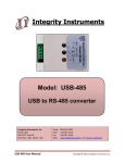
1
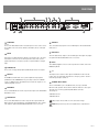
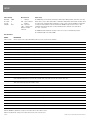
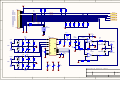
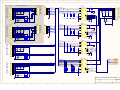
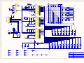
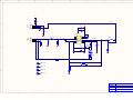
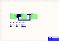
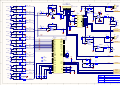
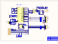
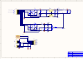
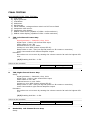
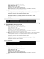
SERVICE INFORMATION
IN400
AV CONTROLLER
CONTENTS:
OPERATION MANUAL
SCHEMATIC DIAGRAMS
TEST PROCEDURE
Australian Monitor
1 Clyde Street, Silverwater NSW 2128 Australia
+61 2 9647 1411
www.australianmonitor.com.au
IN400
AV SWITCHING AMPLIFIER
INSTALLATION AND OPERATION MANUAL
IMPORTANT SAFETY INFORMATION
PRÉCAUTIONS DURANT UTILISATION
1.
Read these instructions.
1.
LISEZ ces instructions.
2.
Keep these instructions.
2.
Tenez ces instructions.
3.
Heed all warnings.
3.
Notez tous les avertissements.
4.
Follow all instructions.
4.
Suivez toutes les avertissements.
5.
Do not use this apparatus near water.
5.
N’utilisez pas ce produit près de l’eau (la piscine, la plage, le lac, etc.).
6.
Clean only with dry cloth.
6.
Nettoyez seulement avec une étoffe sèche.
7.
Do not block any ventilation openings. Install in accordance with the
manufacturer’s instructions.
7.
Ne bloquez aucuns troux de ventilation. Installez en accord avec
les instructions du manufacturier.
8.
Do not install near any heat sources such as radiators, heat registers,
stoves, or other apparatus (including amplifiers) that produce heat.
8.
N’installez près aucunes sources de chaleur comme radiateurs,
registres de chaleur, fours ou les autres équipements (y compris
amplificateurs) qui produisent la chaleur.
9.
Do not defeat the safety purpose of the polarized or grounding-type
plug. A polarized plug has two blades with one wider than the other.
A grounding type plug has two blades and a third grounding prong.
The wide blade or the third prong are provided for your safety. If the
provided plug does not fit into your outlet, consult an electrician for
replacement of the obsolete outlet.
9.
Ne défaites pas le but de sécurité de la fiche polarisée ou base-type.
Une fiche polarisée a deux tranchants avec un plus large que l’autre.
Une fiche de base type a deux a deux tranchants et une troisième
pointe de base, le tranchant large ou la troisième pointe est fourni
pour votre sécurité. Si la fiche donnée ne conforme pas votre prise
de contact, consultez un électricien pour remplacement de la prise
de contact obsolète.
10. Protect the power cord from being walked on or pinched particularly
at plugs, convenience receptacles, and the point where they exit from
the apparatus.
11. Only use attachments/accessories specified by the manufacturer.
12. Use only with the cart, stand, tripod, bracket, or table
specified by the manufacturer, or sold with the
apparatus. When a cart is used, use caution when
moving the cart/apparatus combination to avoid injury
from tip-over.
13. Unplug this apparatus during lightning storms or when
unused for long periods of time.
14. Refer all servicing to qualified service personnel. Servicing is required
when the apparatus has been damaged in any way, such as powersupply cord or plug is damaged, liquid has been spilled or objects have
fallen into the apparatus, the apparatus has been exposed to rain or
moisture, does not operate normally, or has been dropped.
15. This appliance shall not be exposed to dripping or splashing water and
that no object filled with liquid such as vases shall be placed on the
apparatus.
16. Plug this apparatus to the proper wall outlet and make the plug to be
disconnected readily operable.
17. Main plug is used as disconnected device and it should remain readily
operable during intended use. In order to disconnect the apparatus from
the mains completely, the mains plug should be disconnected from the
mains socket outlet completely.
10. Protegez le cordon de secteur contre être marchée dessus ou pincez
en particulier aux fiches, aux douilles de convenance, et au point où ils
sortent de l’appareil.
11. Seulement utilisez attachements/accessoires spécifiés par le
manufacturier.
12. Utilisez seulement avec un chariot, un stand, un
trépied, un support ou une table indiquée par le
manufacturier, ou vendue avec l’appareil. Quand un
chariot est utilisé, faites attention en déplaçant la
combinaison d’appareil/chariot pour éviter de se
déséquilibrer.
13. Arrachez la fiche du dispositif durant éclair et orage ou quand
pas utilisé pour longues périodes de temps.
14. Référez au personnel qualifié de service pour toutes réparations.
La réparation est donnée quand le système a été endommagé à
n’importe façon, par exemple un fil ou une fiche endommagé(e)
de la source d’alimentation. Avoir été exposé à pluie ou humidité,
n’opère pas normalement, ou avoir été tombé.
15. L’appareil ne doit pas être exposé aux écoulements ou aux
éclaboussures et aucun objet ne contenant de liquide, tel qu’un vase,
ne doit être placé sur l’objet.
16. Branchez l’appareil à une source appropriée et faire que la prise à
débrancher soit facilement accessible.
18. WARNING: To reduce the risk of fire or electric shock, do not expose this
apparatus to rain or moisture.
17. La prise du secteur ne doit pas être obstruée ou doit être facilement
accessible pendant son utilisation. Pour être complètement déconnecté
de l’alimentation d’entrée, la prise doit être débranchée du secteur.
19. An appliance with a protective earth terminal should be connected to a
mains outlet with a protective earth connection.
18. AVERTISSEMENT: Pour éviter le risque d’incendie ou de chocs
électriques, ne pas exposer cet appareil à la pluie ou à l’humidité.
19. Un appareil avec la borne de terre de protection doit être connecté au
secteur avec la connexiion de terre de protection.
INTRODUCTION AND CONTENTS
The Innovation series from AMAV is a huge step forward in the interfacing and
management of audio and visual sources. Integrating a host of smart, high end
features in a compact package that offers the end user extremely simple control
over their complex audio visual system. The Innovation series is as ground
breaking as it is simple to operate.
The IN400 is a compact AV switching amplifier with a host of extra features
available to the AV integrator. With 8 AV inputs as well as mix in, stereo line
output, 2 composite video outputs, VGA video output, 80 watt per channel
powered outputs, IR control, RS485 control and video away from audio split the
IN400 is perfect for boardroom, lecture theatre or training facility installations as
a stand alone control unit or as part of a larger system interfacing with a third
party control system.
INTRODUCTION
3
FRONT PANEL
4
REAR PANEL
5
SETUP
6
INSTALLATION
7
BLOCK DIAGRAM
8
DIMENSIONS
9
SPECIFICATIONS
10
AUS, EUR, USA
Copyright 21st Aug 2008
REV A 21st Aug 2008
REV B 9th Dec 2008
REV C 8th Apr 2010
REV D 7th June 2010
WARNING!
TO PREVENT FIRE OR SHOCK HAZARD, DO NOT USE THE PLUG WITH AN EXTENSION CORD, RECEPTACLE OR
OTHER OUTLET UNLESS THE BLADES CAN BE FULLY INSERTED TO PREVENT BLADE EXPOSURE.
TO REDUCE THE RISK OF FIRE OR ELECTRIC SHOCK, DO NOT EXPOSE THIS APPLIANCE TO RAIN OR MOISTURE.
TO PREVENT ELECTRICAL SHOCK, MATCH WIDE BLADE PLUG TO WIDE SLOT, FULLY INSERT.
CAUTION
RISK OF ELECTRIC SHOCK
DO NOT OPEN
The lightning flash with arrowhead symbol,
within an equilateral triangle, is intended
to alert the user to the presence of
uninsulated “dangerous voltage” within
the product’s enclosure that may be of
sufficient magnitude to constitute a risk
of electric shock to persons.
WARNING: TO REDUCE THE RISK
OF ELECTRIC SHOCK, DO NOT
REMOVE COVER (OR BACK).
NO USER SERVICEABLE PARTS INSIDE.
REFER SERVICING TO QUALIFIED
SERVICE PERSONNEL.
The exclamation point within an equilateral
triangle is intended to alert the user to
the presence of important operating and
maintenance (servicing) instructions in the
literature accompanying the appliance.
Rating plate and caution marking are marked on the back enclosure of the apparatus
IN400 INSTALLATION AND OPERATION MANUAL
PAGE 3
FRONT PANEL
6
8
4
5 7
3
2
1
1 MASTER VOLUME
This pot controls the audio output level.
2 MASTER VOLUME LEDS
These LED’s indicate the position of the volume control. They do not indicate the
strength of the signal.
3 SOURCE SELECT SWITCHES
These switches select the input that is routed to the audio and video outputs.
4 SOURCE SELECT LEDS
The LED above the switch indicates when the channel is being routed to the
outputs.
LED State
1. A solid LED means that both audio and video from that source is routed to the
respective outputs.
2. A long flasing LED means that audio from that source is routed to the audio
output.
3. A short flasing LED means that video from that source is routed to the video
output.
Source audio and video splitting is achievable through RS485. See the section on
Communications on page 6 for more information.
5 POWER SWITCH
This switch switches the unit on.
6 POWER ON LED
This indicates the unit is on.
7 IR SENSOR
This is the sensor used for IR control. A hand held remote control is supplied with
the IN400. Line of sight is required for the remote control to work.
8 COMMS LED
This LED indicates when data is sent or revceived via IR or RS485.
PAGE 4
IN400 INSTALLATION AND OPERATION MANUAL
REAR PANEL
4
11
1
2
3
5
6
10 9
1 AUDIO INPUT
Sources
These are the RCA unbalanced line level audio inputs for each of the 8 sources.
The top RCA connector is the left channel, bottom RCA connector is the right
channel.
7
8
7 VGA INPUT
These are high densisty 15pin D connector VGA inputs for the PC1/PC2/AUX3/
AUX4 sources.
8 VGA OUTPUT
2 MIX IN
This input is not switched but mixes with the selected audio source. The bass/
treble/volume controls do not affect this input. This feature can be used in
paging environments or emergency systems in conjuction with the L1 trigger
input.
3 AUDIO OUTPUT
These are the left (top) and right (bottom) RCA unbalanced line level outputs.
4 AMP OUT
The IN400 has a built in audio stereo power amplifier. The input signal is
parallelled from the AUDIO OUTPUT. The power amp is rated at 2 x 80W into
4 ohm, 2 x 50W into 8ohm. The minimum load is 4ohm. The outputs are on a
5.08mm pluggable connector.
5 VIDEO INPUT
These are RCA unbalanced 75ohm composite video inputs for the DVD1/DVD2/
AUX1/AUX2 sources.
6 VIDEO OUTPUT
These are the RCA unbalanced 75ohm composite video outputs. OUT1 and
OUT2 output the same signal but they are individually buffered. These outputs
only output the signal from DVD1/DVD2/AUX1/AUX2 sources if selected.
IN400 INSTALLATION AND OPERATION MANUAL
This is the high densisty 15pin D connector VGA output. This output only outputs
the signal from PC1/PC2/AUX3/AUX4 sources if selected.
9 RS485
This 5.08mm pluggable connector socket is provided for external control of the
IN400 using RS485.
10 L1
This input is used to mute the audio outputs. The MIX IN is not affected. This
feature can be used in paging environments or emergency systems. Short it to
the RS485 ground pin to activate it.
11 IEC MAINS INPUT SOCKET
This is a standard IEC 3 pin socket (IEC320-C14). It accepts a standard
IEC mains cable, provided. The fuse draw contains the mains fuse and a spare.
The mains fuse is a time lag (slow blow) HRC 20mm x 5mm fuse.
The ratings are:
230V Model T3.15A
120V Model T6.3A
Always replace the fuse with one of the same value and type.
Note: Always disconnect power to the amplifier before replacing fuses.
PAGE 5
SETUP
RS485 Settings
Word Structure
RS485 Setup
Baud Rate:
No. of Bits:
Stop Bit:
Parity Bit:
! - Start byte
XXX - 3 byte command
: - delimiter
XXX - 3 byte data
<CR> - carriage return
All bytes are ASCII
characters.
The IN400 data port is an RS485 serial data port. Twisted pair cabling should be used when connecting
RS485 devices, such as CAT3, CAT5, CAT5e or CAT6 UTP cabling. RS485 data networks should be wired
in a ‘daisy chain’ configuration with a maximum of 32 devices in the chain. The IN400 is not terminated
so may be inserted anywhere in the data network. If the IN400 is being used at the end of a chain,
a 120ohm (characteristic impedance of UTP) terminating resistor should be connected between
the + and - connections.
9600
8
1
None
The IN400 has built in failsafe bias circuitry so there are no need for external biasing resistors.
The maximum length of the chain is 500m.
Data Commands
COMMS
DESCRIPTION
!VER:???<CR>
Version request. Device replies with !VER=xyz where xyz is the version ID of the firmware.
!GMD:???<CR>
Global Mode request. Device replies with !GMD=00x, where x is 0 if global mode is not active and 1 if global mode is active.
!LOK:???<CR>
Panel Lock request. Device replies with !LOK=00x, where x is 0 if panel lock is not active and 1 if panel lock is active.
!PWR:???<CR>
Soft Power request. Device replies with !PWR=00x, where x is 0 if soft power state if off and 1 if soft power state is on.
!BAS:???<CR>
Bass request. Device replies with !BAS=0xy, where xy is the current setting of bass.
!TRE:???<CR>
Treble request. Device replies with !TRE=0xy, where xy is the current setting of treble.
!VOL:???<CR>
Volume request. Device replies with !VOL=xyz, where xyz is the current setting of volume.
!MUT:???<CR>
Mute request. Device replies with !MUT=0xy, where x represents the audio mute and y represents the video mute.
!SRS:???<CR>
Source request. Device replies with !SRS=0xy, where x represents the audio source and y represents the video source.
!GMD:000<CR>
Global Mode set. Global mode is deactivated. Device replies with !GMD=000 when done.
!GMD:001<CR>
Global Mode set. Global mode is activated. Device replies with !GMD=001 when done.
!LOK:000<CR>
Panel Lock set. Panel lock is deactivated. Device replies with !LOK=000 when done.
!LOK:001<CR>
Panel Lock set. Panel lock is activated. Device replies with !LOK=001 when done.
!PWR:000<CR>
Soft Power set. Device is put into soft power off. Device replies with !PWR=000 when done.
!PWR:001<CR>
Soft Power set. Device is put into soft power on. Device replies with !PWR=001 when done.
!MUT:0xy<CR>
Mute set. If x is 0, the audio is muted. If y is 0, the video is muted. If x is 1, the audio is unmuted. If y is 1, the video is unmuted. Device
replies with !MUT=0ab, where a represents the new audio mute state and b represents the new video mute state.
!SRS:0xy<CR>
Source Select set. The audio source is set to x. The video source is set to y. Device replies with !SRS=0ab, where a represents the new
audio source and b represents the new video source.
!VOL:xyz<CR>
Volume set. The volume is set to xyz. The device replies with !VOL=abc where abc is the new volume.
!VOL:+++<CR>
Volume increment. The volume is incremented by 1. The device replies with !VOL=abc where abc is the new volume.
!VOL:---<CR>
Volume decrement. The volume is decremented by 1. The device replies with !VOL=abc where abc is the new volume.
!BAS:0xy<CR>
Bass set. The bass is set to xy. The device replies with !BAS=0ab where ab is the new bass.
!BAS:+++<CR>
Bass increment. The bass is incremented by 1. The device replies with !BAS=0ab where ab is the new bass.
!BAS:---<CR>
Bass decrement. The bass is decremented by 1. The device replies with !BAS=0ab where ab is the new bass.
!TRE:0xy<CR>
Treble set. The treble is set to xy. The device replies with !TRE=0ab where ab is the new treble.
!TRE:+++<CR>
Treble increment. The treble is incremented by 1. The device replies with !TRE=0ab where ab is the new treble.
!TRE:---<CR>
Treble decrement. The treble is decremented by 1. The device replies with !TRE=0ab where ab is the new treble.
Global Mode
When the IN400 is in global mode, changes to the volume and tone affect all the sources.
When not in global mode, changes to the volume and tone affects the selected source.
PAGE 6
IN400 INSTALLATION AND OPERATION MANUAL
INSTALLATION
All installation work should be done with the power disconnected. The following inforamtion will help with installation. After installation is complete power up all the
sources before turning on the IN400.
POWER CONNECTION
OUTPUT CONNECTIONS (cont.)
Ensure the mains voltage supply matches the rear of the IN400 (+/- 10%)
Video
Video outputs are on either unbalanced RCA sockets (composite) or 15 pin high
density female connectors D-connectors (VGA). The maximum cable length for
composite video is typically less than 3m for shielded wire and 10m for coaxial
before signal degradation. This will depend on the cable quality.
Ensure that all system grounds (earth) are connected to a common point. Avoid
powering equipment within a system from multiple power sources that may be
separated by large distances. This will eliminate ground loops that are heard as
50/60Hz humming or buzzing in speakers and seen as moving or stationary bars
on video equipment.
INPUT CONNECTIONS
Audio
All the inputs are unbalanced RCA sockets. Unbalanced RCA wiring should be
keep as short as possible. Typically less than 3m.
Video
Video inputs are on either unbalanced RCA sockets (composite) or 15 pin high
density female connectors D-connectors (VGA). The maximum cable length for
composite video is typically less than 3m for shielded wire and 10m for coaxial
before signal degradation. This will depend on the cable quality.
OUTPUT CONNECTIONS
Audio
The line level outputs are unbalanced RCA sockets. Unbalanced RCA wiring should
be keep as short as possible. Typically less than 3m.
The amplifier outputs are 5.08mm pluggable connectors. Use the following table
for selecting a suitable guage wire for the cable you are running over a particular
distance. The table is for a 1dB drop in level which is generally considered
acceptable.
AWG10 AWG13 AWG14 AWG16 AWG17 AWG18 AWG20 AWG22 AWG24 AWG26
Speaker
16
279
125
100
75
51
38
26
17
11
6
8
139
62
50
37
26
19a
13
9
6
3
4
70
31
25
19
13
10
There are two composite outputs for running to 2 different monitors without the
need for an external distribution amplifier.
VGA pin out
1
Red out
2
Green out
3
Blue out
4
Monitor ID 2 in
5
Ground
6
Red return
7
Green return
8
Blue return
9
no pin
10 Sync return
11 Monitor ID 0 in
12 Monitor ID 1 in
13 Horizonal Sync out
14 Vertical Sync out
15 reserved (monitor ID 3)
Only pins 1,2,3,5,6,7,8,10,13,14 are used in the IN400.
RS485 CONNECTIONS
The RS485 data port is on a 5.08mm pluggable connectors. Twisted pair cabling
should be used When connecting RS485 devices, such as CAT3, CAT5, CAT5e
or CAT6 UTP cabling. RS485 data networks should be wired in a ‘daisy chain’
configuration with a maximum of 32 devices in the chain. The IN400 is not
terminated so may be inserted anywhere in the data network. If the IN400 is
being used at the end of a chain, a 120ohm (characteristic impedance of UTP)
terminating resistor should be connected between the + and - connections.
The maximum length of the chain is 500m.
Do not connect a total impedance of less than 4ohm per channel.
IN400 INSTALLATION AND OPERATION MANUAL
PAGE 7
BLOCK DIAGRAM
PAGE 8
IN400 INSTALLATION AND OPERATION MANUAL
DIMENSIONS
IN400 INSTALLATION AND OPERATION MANUAL
PAGE 9
SPECIFICATIONS
POWER OUTPUT (0.5%THD, 1kHz)
8ohm 50W,
4ohm 80W
THD (20-10kHz, 8ohm, -2dBr)
Better than 0.1%
Frequency Response(+/-3dB)
20-20kHz
Gain
24dB @ 8ohm
Line Audio THD
Noise Floor
Frequency Response(+/-3dB)
Headroom
Video
VGA
Video
Video follows Audio switching
Comms
Type
Baud Rate
No of Data Bit
Parity
No of Stop Bits
Power Consumption
Thermal output
SIZE (WXHXD)
<0.5%
-90dBu
20Hz-20kHz
+5dBu
High speed RGB+Sync switching
Composite 75ohm Buffered outputs
RS485
9600
8
None
1
1/8th power 150VA (0.65A)
1/8th power 100W (341.2Btu/hr)
482 x 44 x 325mm
19 ” x 1.75” x 12.8”
NET WEIGHT
7.0kg
15.4lb
SHIPPING WEIGHT
9.0kg
19.8lb
SHIPPING DIMENSIONS (WXHXD)
PAGE 10
520 x 90 x 420 mm
19.0” x 3.5” x 16.5”
IN400 INSTALLATION AND OPERATION MANUAL
AUSTRALIA AND NEW ZEALAND
www.australianmonitor.com.au
SYDNEY
MELBOURNE
ADELAIDE
AUCKLAND
(NSW SALES)
(VIC & TAS SALES)
(SA & NT SALES)
(NZ SALES)
1 Clyde Street
Silverwater
NSW 2128
Private Bag 149
Silverwater NSW 1811
Phone: (02) 9647 1411
Fax: (02) 9648 3698
Email:
[email protected]
22/277
Middleborough Road
Box Hill VIC 3128
PO Box 151 Blackburn
South VIC 3130
Phone: (03) 9890 7477
Fax: (03) 9890 7977
Email:
[email protected]
31 Walsh Street
Thebarton
SA 5031
PO Box 157
Hindmarsh SA 5007
Phone: (08) 8352 4444
Fax: (08) 8352 4488
Email:
[email protected]
9C Piermark Drive
Albany 0752
New Zealand
PO Box 300-512
Albany 0752
Phone: (09) 415 9426
Fax: (09) 415 9864
Email:
[email protected]
CANBERRA
BRISBANE
PERTH
(ACT SALES)
(QLD SALES)
(WA SALES)
1st Floor,
Campion Street
Deakin ACT 2600
PO Box 109
Deakin West ACT 2600
Phone: (02) 6260 4544
Fax: (02) 6260 4744
Email: gordon.anderson@
hillssvl.com.au
42 Commercial Road
Fortitude Valley
QLD 4006
PO Box 2578 Fortitude
Valley BC QLD 4006
Phone: (07) 3852 1312
Fax: (07) 3252 1237
Email:
[email protected]
3/11 Howe Street
Osborne Park WA 6017
PO Box 1281
Osborne Park BC
WA 6916
Phone: (08) 9204 0200
Fax: (08) 9244 3783
Email:
[email protected]
EUROPE / ASIA / MIDDLE EAST
www.australianmonitor.com.au
INTERNATIONAL SALES
1 Clyde Street Silverwater NSW 2128 Australia
Private Bag 149 Silverwater NSW 1811
Phone: + 61 2 9647 1411
Fax: + 61 2 9748 2537
Email: [email protected]
1
2
3
4
A
A
Composite Switching & Main Board Connection
CD6383-1-B.SchDoc
RGBHV Switching
CD6383-2-B.SchDoc
VGA-EN
VGA-SD
VGA-A0
VGA-A1
VGA-EN
VGA-SD
VGA-A0
VGA-A1
B
B
MH1
Mounting Hole
MH2
Mounting Hole
MH3
Mounting Hole
MH4
Mounting Hole
FID1
FIDUCIAL
FID2
FIDUCIAL
FID3
FIDUCIAL
FID4
FIDUCIAL
FID5
FIDUCIAL
C
C
Australian Monitor IN400
D
1
2
3
D
4
1
2
3
4
+5VD
CN1
+5V
+5V
VGA-A0
VGA-A1
VGA-EN
VGA-SD
CMP-A0
CMP-A1
CMP-EN
CMP-SD
GND
GND
DIP1
DIP2
-5V
-5V
1
2
3
4
5
6
7
8
9
10
11
12
13
14
15
16
R1
47k
RP1
100
R5
100
RP2
100
R2
47k
R3
47k
R4
47k
A
VGA-A0
VGA-A1
VGA-EN
VGA-SD
COMP-A0
COMP-A1
COMP-EN
COMP-SD
VGA-A0
VGA-A1
VGA-EN
VGA-SD
R6
47k
DIP1
DIP2
R12
100
R7
47k
R8
47k
R9
47k
R10
47k
R11
47k
3
1
A
SW1
2pole DIP
To Main Board
VGND
B
VGND
R75
D1
PGB1010603
1
5
D28
R17
75
C
AUX2
PGB1010603
6
5
R19
75
PGB1010603
2
14
C3
0.1uF
DVD2
D
PGB1010603
D6
2
4
4.7uF
GND
GND
V-
VGND
10
11
8
9
VGND
R70
6k8
R71
470
-5VD
R20
560
C4
0.1uF
6
R21
560
VGND
-5VD
R14
75
C2
0.1uF
VIDEO OUT
D2
PGB1010603
VGND
CN3
VGND
U1B
LT6206
C
D4
PGB1010603
VIDEO OUT
5
7
6
D30
R23
75
R18
10k
C17
4.7uF
4.7uF
R22
75
VGND
R73
10k
BAS40
+5VD
CN2A
3
VGND
V+
VGND
3
2
R16
150
12
IN3
EN
SD
A0
A1
U1A
LT6206
1
+5VD
R72
10k
BAS40
C19
D5
VGND
FB
D27
BAS40
13
R15
1k5
IN2
7
D29
OUT
IN1
BAS40
C18
DVD1
IN0
3
R13
10k
CN2B
D3
C16
4.7uF
U2
LMH6574MA
C1
0.1uF
8
VGND
C15
4.7uF
AUX1
+5VD
AOT
4
-5VD
4
2
B
VGND
+5VD
VGND
D31
R26
75
R25
560
VGND
R74
10k
C5
22uF
BAS40
C20
4.7uF
R24
560
VGND
C6
22uF
-5VD
C7
22uF
Australian Monitor IN400
-5VD
D
CD6383-1
1
2
3
4
SGND
ID0
ID1
HSYNC
VSYNC
ID3
DVD1
U3
LMH6574MA
DVD1-R
1
DVD1-G
DVD2-R
3
DVD1-B
PC1-R
5
DVD1-V
PC2-R
7
R31
75
DVD1
R32
75
R33
75
R34
75
14
VGND
R35
AOT
D13
SP0502BAHTG
R36
10k
2
4
SGND
ID0
ID1
HSYNC
VSYNC
ID3
10
9
8
7
6
5
4
3
2
1
PGB1010603
D17
PGB1010603
D16
PGB1010603
D15
CN10
-5VD
RGND
RED
GGND
GREEN
BGND
BLUE
SGND
VSYNC
GND
HSYNC
10
9
8
7
6
5
4
3
2
1
DVD1-G
1
PC1-R
DVD2-G
3
PC1-G
PC1-G
5
PC1-B
PC2-G
7
R41
75
PC1-H
R42
75
R43
75
R44
75
14
C10
0.1uF
PC1
2
4
R45
AOT
D18
R46
10k
R47
10k
VGA OUT
VGND
R39
560
IN1
IN2
SP0502BAHTG
R38
75
13
OUT
12
FB
R40
560
IN3
VGND
V+
GND
GND
VGA-EN
VGA-SD
VGA-A0
VGA-A1
10
11
8
9
EN
SD
A0
A1
B
C11
0.1uF
6
V-
-5VD
DVD1-B
1
DVD2-B
3
PC1-B
5
PC2-B
7
PGB1010603
D21
PGB1010603
D20
PGB1010603
D19
VGND
IN0
R49
560
IN1
IN2
R48
75
13
OUT
12
FB
R50
560
IN3
VGND
+5VD
R51
75
R52
75
R53
75
R54
75
14
C12
0.1uF
2
4
V+
GND
GND
VGA-EN
VGA-SD
VGA-A0
VGA-A1
10
11
8
9
EN
SD
A0
A1
C13
0.1uF
6
V-
C
DVD2-H
DVD2-V
VGND
R55
AOT
D22
SP0502BAHTG
R56
10k
U6
M74HCT153M1R
6
5
4
3
DVD1-V
DVD2-V
PC1-V
PC2-V
10
11
12
13
3k3
3k3
3k3
3k3
PGB1010603
VGND
R66
R67
R68
R69
1C0
1C1
1C2
1C3
Y1
2C0
2C1
2C2
2C3
Y2
7
R58
75
VGA-EN
VGA-SD
9
VGA-A0
R59
75
VGA-A1
VGA-EN
VGA-SD
VGA-A0
VGA-A1
+5VD
16
R27
R63
R64
R65
D25
PGB1010603
D24
D23
PGB1010603
PC2-R
PC2-G
PC2-B
DVD1-H
DVD2-H
PC1-H
PC2-H
3k3
3k3
3k3
3k3
CN12
1
2
3
4
5
6
7
8
9
10
11
12
13
14
15
-5VD
R57
10k
VGND
D
VGND
U5
LMH6574MA
DVD2-R
DVD2-G
DVD2-B
1
2
3
4
5
6
7
8
9
10
11
12
13
14
15
DVD2
SGND
ID0
ID1
HSYNC
VSYNC
ID3
IN0
VGND
CN11
RED
GREEN
BLUE
ID2
GND
RGND
GGND
BGND
SGND
ID0
ID1
HSYNC
VSYNC
ID3
+5VD
PC1-V
VGND2
SGND
ID0
ID1
HSYNC
VSYNC
ID3
C14
0.1uF
PC2-H
PC2-V
8
VCC
1OE
2OE
GND
A
B
1
15
VGA-EN
14
2
VGA-A0
VGA-A1
D
PC2
R60
AOT
D26
SP0502BAHTG
R61
10k
R62
10k
VGND
Australian Monitor IN400
VGND
CD6383-2
1
A
VGND
SP0502BAHTG
C
C9
0.1uF
6
V-
OUT-H
OUT-V
RED
GREEN
BLUE
ID2
GND
RGND
GGND
BGND
D14
PC1
PC1
RED
GREEN
BLUE
ID2
GND
RGND
GGND
BGND
GND
GND
EN
SD
A0
A1
U4
LMH6574MA
CN8
B
VGND
VGA-EN
VGA-SD
VGA-A0
VGA-A1
10
11
8
9
VGND
CN9
1
2
3
4
5
6
7
8
9
10
11
12
13
14
15
R30
560
IN3
V+
1
2
3
4
5
6
7
8
9
10
11
12
13
14
15
12
FB
R37
10k
VGND1
RED
GREEN
BLUE
ID2
GND
RGND
GGND
BGND
CN7
OUT-R
OUT-G
OUT-B
R29
560
IN1
IN2
R28
75
13
OUT
+5VD
DVD1-H
C8
0.1uF
DVD1
IN0
D12
DVD1-R
PGB1010603
10
9
8
7
6
5
4
3
2
1
8
D11
RGND
RED
GGND
GREEN
BGND
BLUE
SGND
VSYNC
GND
HSYNC
7
PGB1010603
CN6
10
9
8
7
6
5
4
3
2
1
PGB1010603
D9
PGB1010603
D8
PGB1010603
1
2
3
4
5
6
7
8
9
10
11
12
13
14
15
D7
A
RED
GREEN
BLUE
ID2
GND
RGND
GGND
BGND
6
2
CN5
CN4
5
D10
TO BE PLACED ON BREAK-OFF PCB
4
PGB1010603
3
1
2
3
1
2
3
4
5
6
7
8
3
LVOL9
LVOL10
LVOL11
LVOL12
4
5
6
7
8
9
10
11
LSRC1
LSRC2
LSRC3
LSRC4
LSRC5
LSRC6
LSRC7
LSRC8
13
14
15
16
17
18
19
20
LSRCOFF
LPOWER
LCOMMS
TP4
GND
12
GND
+5V
Red 3mm
1k8
R43
470
SWPOWER
LPOWER
LCOMMS
D21
10nF
10nF
10nF
B
R21
1k8
D2
R22
1k8
D3
R23
1k8
D4
R24
1k8
D5
R25
1k8
D6
R26
1k8
D7
D22
R50
1k8
R51
1k8
Blue 3mm
D1
D23
R52
1k8
LVOL12
LVOL11
LVOL10
LVOL9
LVOL8
LVOL7
LVOL6
LVOL5
LVOL4
LVOL3
LVOL2
LVOL1
C
D8
Volume 1
C13
10nF
Comms
Blue 3mm
Power
SW10
Power
Switch
D20
R29
47k
R30
10nF
GND
GND
L8
Ferrite
10nF
R31
470
D9
R32
470
D10
R33
470
D11
R34
470
D12
R35
470
D13
R36
470
D14
R37
470
D15
R38
470
D16
R39
470
D17
R40
470
D18
R41
470
Grn 2mm
GND
10nF
Volume 12
R53
47k
IO1.0
IO1.1
IO1.2
IO1.3
IO1.4
IO1.5
IO1.6
IO1.7
10nF
Grn 2mm
C12
10nF
A0
A1
A2
10nF
Volume 11
C
21
2
3
10nF
Source Off
Source Off
R28
10k
INT
SCL
SDA
C16
Grn 2mm
1
22
23
IO0.0
IO0.1
IO0.2
IO0.3
IO0.4
IO0.5
IO0.6
IO0.7
C15
Source 8
SW9
Alpha Switch
Volume 10
GND
FP-SCL
FP-SDA
C11
10nF
VCC
R49
10k
C8
Source 7
SW8
Alpha Switch
Blue 3mm
A
C
B
R48
47k
C7
Source 6
SW7
Alpha Switch
Grn 2mm
A
C
B
R19
10k
R47
47k
C6
Source 5
SW6
Alpha Switch
Source 8
U4
PCA9555D
C17
0.1uF
C5
Source 4
SW5
Alpha Switch
Volume 9
RE1
Alpha Encoder
R18
10k
C4
Source 3
SW4
Alpha Switch
Blue 3mm
R17
10k
C3
Source 2
SW3
Alpha Switch
A
GND
+5V
24
C2
Source 1
SW2
Alpha Switch
LSRCOFF
LSRC8
LSRC7
LSRC6
LSRC5
LSRC4
LSRC3
LSRC2
LSRC1
GND
+5V
L10
Ferrite
SWSRCOFF
SW1
Alpha Switch
Source 7
GND
13
14
15
16
17
18
19
20
L9
Ferrite
SWSRC8
Grn 2mm
12
LVOL1
LVOL2
LVOL3
LVOL4
LVOL5
LVOL6
LVOL7
LVOL8
Blue 3mm
TP2
GND
IO1.0
IO1.1
IO1.2
IO1.3
IO1.4
IO1.5
IO1.6
IO1.7
4
5
6
7
8
9
10
11
Source 5
R20
47k
IO0.0
IO0.1
IO0.2
IO0.3
IO0.4
IO0.5
IO0.6
IO0.7
Grn 2mm
A0
A1
A2
L7
Ferrite
SWSRC7
Volume 6
INT
SCL
SDA
21
2
3
GND
L6
Ferrite
Blue 3mm
1
22
23
To Main PCB
L5
Ferrite
SWSRC5
Source 4
R16
10k
FP-SCL
FP-SDA
FP-INT
ENCA
ENCB
IR-RX
L4
Ferrite
SWSRC4
Grn 2mm
R15
47k
GND
L3
Ferrite
SWSRC3
Volume 5
R14
47k
FP-SCL
VCC
L1
Ferrite
L2
Ferrite
Blue 3mm
C10
0.1uF
R46
47k
SWSRC2
U2
PCA9555D
24
C9
10uF
FP-SDA
R27
47k
SWSRC6
+5V
1
2
3
4
5
6
7
8
9
10
R7
47k
Source 3
TP1
+5V
R6
47k
Volume 8
GND
R5
47k
SWSRC1
GND
CN1
B
12
R4
47k
Grn 2mm
TP3
GND
+5V
IO1.0
IO1.1
IO1.2
IO1.3
IO1.4
IO1.5
IO1.6
IO1.7
SWSRCOFF
SWPOWER
R3
47k
Blue 3mm
U3
TSOP36238
GND
+5V
+5V
SDA
GND
SCL
GND
IRQ
ENCA
ENCB
IR
A0
A1
A2
13
14
15
16
17
18
19
20
R2
47k
Source 6
21
2
3
GND
GND
R1
47k
Grn 2mm
IR-RX
SWSRC1
SWSRC2
SWSRC3
SWSRC4
SWSRC5
SWSRC6
SWSRC7
SWSRC8
Volume 4
OUT
2
1
INT
SCL
SDA
4
5
6
7
8
9
10
11
Blue 3mm
4
1
22
23
IO0.0
IO0.1
IO0.2
IO0.3
IO0.4
IO0.5
IO0.6
IO0.7
Source 2
FP-INT
FP-SCL
FP-SDA
V+
VCC
R13
10k
Grn 2mm
3
C14
10uF
R12
47k
Volume 3
GND
R44
100
R11
47k
Blue 3mm
GND
R10
47k
Volume 7
24
R9
47k
8
+5V
IR-RX
R8
47k
7
U1
PCA9555D
GND
1
6
Source 1
3
A
+5V
C1
0.1uF
V+
OUT
5
Grn 2mm
+5V
U3A
TSOP32238
2
4
Volume 2
2
Grn 2mm
1
D19
R42
470
GND
MH1
Mounting Hole
MH9
Mounting Hole
MH8
Mounting Hole
MH4
Mounting Hole
MH2
Mounting Hole
MH10
Mounting Hole
MH7
Mounting Hole
MH5
Mounting Hole
MH3
Mounting Hole
MH6
Mounting Hole
D
D
Project
FID1
FIDUCIAL
FID2
FIDUCIAL
FID3
FIDUCIAL
Number
FID4
FIDUCIAL
Name
Australian Monitor
IN400
Front Panel Board
Date
1
2
3
4
5
6
7
8
1
2
3
4
5
6
7
8
A
A
+35V
F1
3.15A Slow
OUTPUT
CN1
VV+
GND
Output
1
2
3
4
C1
0.1uF
+35V
To Main PCB
GND
F2
3.15A Slow
C2
47uF
GND
U1
LM3886TF
B
-35V
C3
10uF BP
CN2
Input
Mute
In Shld
1
2
3
INPUT
To Main PCB
11
2
R13
R12
4k7
Link
R2
100k
R1
Link
NC
NC
+V
+V
NC
10
B
1
5
6
R11
Link
3
C4
220pF
RAWOUTPUT
9
R3
4k7
7
GND
MUT
-V
8
4
R4
LK1
Mute Link
GND
GND
L1
1uH
GND
10 3W
R5
22k
C5
47uF
C6
0.1uF
R6
2.7 3W
C7
0.1uF
C8
47uF
GND
-35V
GND
GND
U2
CNY17-1
MUTE+
C
C
R7
390
R8
MH1
Mounting Hole
16k
MH2
Mounting Hole
C9
220pF
R10
1k
MH3
Mounting Hole
R9
16k
C10
47uF
MH4
Mounting Hole
GND
D
D
Project
Number
Name
Australian Monitor
IN400
Power Amplifier Board
Date
1
2
3
4
5
6
7
8
1
2
3
4
5
6
7
8
A
A
Processor
CD07900-2-E.SchDoc
SPI-MISO
B
FID5
FIDUCIAL
C
Power Supply
CD07900-3-E.SchDoc
Audio Switching
CD07900-1-E.SchDoc
SPI-MOSI
SPI-CS
SPI-SCK
AMP1-MUTE
AMP2-MUTE
OUT1-MUTE
OUT2-MUTE
CTRL-AD
RS485-A
RS485-B
FID6
FIDUCIAL
SPI-MOSI
SPI-CS
SPI-SCK
AMP1-MUTE
AMP2-MUTE
OUT1-MUTE
OUT2-MUTE
CTRL-AD
FID7
FIDUCIAL
CTRL-IN
B
FID8
FIDUCIAL
MH1
Mounting Hole
MH2
Mounting Hole
MH4
Mounting Hole
MH5
Mounting Hole
CTRL-IN
RS485-A
RS485-B
FID9
FIDUCIAL
MH3
Mounting Hole
C
R100
Link
0VAMP
MH6
Mounting Hole
D
D
Project
Number
Australian Monitor
IN400
Name
Date
1
2
3
4
5
6
7
8
D1
SD24C
R2
470
IN1L
INPUT 2 L
D3
SD24C
R8
470
C14
10uF BP
R15
470
C8
10uF BP
IN1R
U2A
MC33204D
R9
+5V
0VMAIN
-5V
0VMAIN
5
D6
SD24C
R21 0VMAIN
22k
C21
10uF BP
R22
470
C12
0.1uF
C23
10uF BP
R27
470
-5V
R16
100k
15
R19
100k
6
D8
SD24C
C18
68pF
C22
10uF BP
IN3R
R25
0VMAIN
13
43k
12
INPUT 4 L
D9
SD24C
R39
470
IN4L
0VMAIN
7
14
4
U2D
MC33204D
R41
22k
Y
R20
47
R30
100k
VCC
Y1
Y0
X
X0
X1
GND
VEE
-5V
4
EXTMIXR
C31
10uF BP
8
C32
0.1uF
IN3L
R23
43k
R35 0VMAIN
22k
C28
10uF BP
R36
470
CN14
1
2
3
R57
47
7
+5V
SIGNAL
MUTE
GND
To Amp 1
R13
10k
U2B
MC33204D
1
2
U3A
MC33202D
C7
0.1uF
R12
1
Z
EN
A
B
C
Z0
Z1
R18
10k
14
12
13
AMP1-MUTE
C10
10uF BP
47
C15
0.1uF
R14
100k
D4
SD24C
0VMAIN
6
11
10
9
A
0VMAIN
3
2
C30
0.1uF
IN2R
R31
22k
R106
470
+5V
0VMAIN
0VMAIN
CN2B
B
U4
CD4053
R10
10k
EXTMIXL
R17
22k
R42
47
100pF
2
5
16
D5
SD24C
INPUT 2 R
INPUT 3 R
R101
100k
R11
47
1
1
3
R5
10k
8
0VMAIN
CN1A
INPUT 3 L
C5
JB1
Signal Jumper Block
0VMAIN
2
43k
IN2L
7
6
4
6
R7 0VMAIN
22k
C11
10uF BP
11
INPUT 1 R
D2
SD24C
6
C4
0.1uF
+5V
CN1B
A
C2
68pF
R1
43k
R4
22k
5
LSND
+5V
LRET
GND
CTRLIN
CTRLAD
RSND
GND
RRET
-5V
C1
10uF BP
4
8
5
3
4
INPUT 1 L
2
1
2
3
4
5
6
7
8
9
10
1
-5V
OUT L
0VMAIN
CN4A
0VMAIN
5
3
OUT R
R26
10k
0VMAIN
OUT1-MUTE
R28
100k
0VMAIN
OUT2-MUTE
B
0VMAIN
CN2A
D10
SD24C
INPUT 4 R
INPUT 5 L
5
D11
SD24C
R44 0VMAIN
22k
C34
10uF BP
R45
470
C35
10uF BP
R46
470
MAINR
MAINL
IN4R
U5
NJW1153
IN1L
IN1R
IN2L
IN2R
IN3L
IN3R
IN4L
IN4R
IN5L
IN5R
IN6L
IN6R
IN7L
IN7R
IN8L
IN8R
IN5L
R48
22k
CN3B
INPUT 5 R
6
D12
SD24C
R51 0VMAIN
22k
C41
10uF BP
R52
470
C43
10uF BP
INPUT 6 L
D13
SD24C
R55
470
IN5R
IN6L
R56
22k
CN3A
C
D14
SD24C
INPUT 6 R
INPUT 7 L
R60 0VMAIN
22k
C49
10uF BP
R61
470
C16
10uF BP
5
D17
SD24C
R34
470
C19
13
14
15
16
17
18
19
20
21
22
23
24
25
26
27
28
32
33
34
35
36
37
IN6R
IN7L
R37
22k
FID1
FIDUCIAL
R40 0VMAIN
22k
C17
10uF BP
FID2
FIDUCIAL
38
39
40
41
42
43
CN5B
INPUT 7 R
6
D18
SD24C
R43
470
C20
10uF BP
INPUT 8 L
D19
SD24C
R47
470
IN7R
44
IN8L
64
1
R50
22k
D20
SD24C
INPUT 8 R
2
3
C46
4.7uF BP
CN5A
R54 0VMAIN
22k
C25
10uF BP
C52 10uF BP
R59
470
48
47
IN8R
46
45
D16
SD24C
R65
100k
R62
22k
C58
220nF
R63
100k
C57
4.7nF
D15
SD24C
C56
220nF
MIX L
C55
4.7nF
D
C54
1uF BP
EXTMIXL
5
INL1
INR1
INL2
INR2
INL3
INR3
INL4
INR4
INL5
INR5
INL6
INR6
INL7
INR7
INL8
INR8
LAIN
RAIN
CAIN
SLAIN
SRAIN
SWAIN
RECL1
RECR1
RECL2
RECR2
RECL3
RECR3
FL+
FLFR+
FRDCLA1
DCLA2
DCRA1
DCRA2
49
50
51
52
53
54
10
0VMAIN
GND
GND
4.7uF BP
C53
V-
C37
10uF BP
47
R33
100k
R67
22k
C
R71
10k
SPI-MOSI
SPI-SCK
SPI-CS
R98
47k
R99
470
Q1
BC847A
R66
470
C3
0.1uF
CTRL-IN
CTRL-IN
D21
SD05
55
4
56
57
C47
0.1uF
C48
10uF
C50
0.1uF
C51
10uF
0VMAIN
SPI-MOSI
-5V
SPI-SCK
SPI-CS
0VMAIN
D
0VMAIN
Number
EXTMIXR
Name
Date
3
CTRL-AD
+5V
R64
29
30
31
CTRL-AD
47
0VMAIN
2
D7
SD24C
0VMAIN
9
10
11
12
Project
6
C24
10uF BP
0VMAIN
C59 10uF BP
1
R29
6
CN4B
MIX R
MC33202D
U3B
R38
10k
+5V
FIL-L1
FIL-L2
FIL-L3
FIL-L4
U2C
MC33204D
AMP2-MUTE
R32
10k
7
FIL-R1
FIL-R2
V+
To Amp 2
8
3
5
R53
47k
FIL-R3
FIL-R4
SIGNAL
MUTE
GND
0VMAIN
C40
10uF BP
DATA
CLOCK
LATCH
1
2
3
9
58
59
60
61
62
63
5
6
7
8
CN15
R58
47
+5VD
LBIN
RBIN
CBIN
SLBIN
SRBIN
SWBIN
SURTC
R24
10k
R102
100k
LOUT
ROUT
COUT
SLOUT
SROUT
SWOUT
R49
47
100pF
4
5
6
7
Australian Monitor
IN400
Main Board
Audio Processing
8
1
2
3
4
FID3
FIDUCIAL
5
6
7
8
FID4
FIDUCIAL
A
A
Extra Decoupling Caps
U9
MC9S08AW16CFGE
+5VD
34
29
C92
0.1uF
C93
0.1uF
30
35
+5VD
VREFH
VDDAD
PTA0
PTA1
VSSAD
VREFL
PTB0/AD1P0
PTB1/AD1P1
PTB2/AD1P2
PTB3/AD1P3
0VMAIN
17
C94
10uF
C95
0.1uF
16
39
PTC0/SCL1
PTC1/SDA1
PTC2/MCLK
PTC3/TXD2
PTC4
PTC5/RXD2
VDD
VSS
VSS
PTD0/AD1P8
PTD1/AD1P9
PTD2/KBI1P5/AD1P10
PTD3/KBI1P6/AD1P11
0VMAIN
C97
22pF
R73
X1
3.6864MHz
B
R74
2M2
37
XTAL/PTG5
PTE0/TXD1
PTE1/RXD1
PTE2/TPM1CH0
PTE3/TPM1CH1
PTE4/SS1
PTE5/MISO1
PTE6/MOSI1
PTE7/SPSCK1
100
38
EXTAL/PTG6
C98
22pF
0VMAIN
+5VD
R82
47k
CN11
BKGD
GND
NC
RESET
NC
VDD
R83
4k7
R84
4k7
2
3
36
R88
1
2
3
4
5
6
PTF0/TPM1CH2
PTF1/TPM1CH3
PTF4/TPM2CH0
PTF5/TPM2CH1
PTG0/KBI1P0
PTG1/KBI1P1
PTG2/KBI1P2
PTG3/KBI1P3
IRQ
RST
BKGD/MS
21
22
VGA-DIP1
VGA-DIP2
23
24
25
26
COMP-SD
COMP-EN
COMP-A1
COMP-A0
40
41
42
43
1
44
I2C-SCL
I2C-SDA
27
28
31
32
VGA-SD
VGA-EN
VGA-A1
VGA-A0
8
9
10
11
12
13
14
15
CTRL-AD
AMP1-MUTE
AMP2-MUTE
SPI-CS
SPI-MISO
SPI-MOSI
SPI-SCK
4
5
6
7
IR-RX
OUT1-MUTE
OUT2-MUTE
+5V
C91
10uF
U1
SN65HVD3082ED
RX-485
A
B
P2
TXEN-485
TX-485
3
4
R103
5
C9
0.1uF
L2
Ferrite
RS485-A
6
R
TX-485
TXEN-485
RX-485
C6
0.1uF
7
RS485-B
Ferrite
L3
GND
C33
1nF
0VMAIN
RS485-A
RS485-B
D22
SM712
C36
1nF
0VMAIN
+5V
FP-ENCA
FP-ENCB
18
19
20
33
B
CN10
VGA-A0
VGA-A1
VGA-EN
VGA-SD
COMP-A0
COMP-A1
COMP-EN
COMP-SD
R75
R76
R77
R78
R79
R80
R81
R85
100
100
100
100
100
100
100
100
VGA-DIP1
VGA-DIP2
R86
R87
100
100
1
2
3
4
5
6
7
8
9
10
11
12
13
14
15
16
FP-INT
100
R89
100
C29
0.1uF
R72
120
D
47k
C13
0.1uF
0VMAIN
8
VCC
2
1
C89
0.1uF
+5V
+5V
VGA-A0
VGA-A1
VGA-EN
VGA-SD
CMP-A0
CMP-A1
CMP-EN
CMP-SD
GND
GND
DIP1
DIP2
-5V
-5V
To Video PCB
C99
0.1uF
C100
0.1uF
+5VD
0VMAIN
-5V
+5VD
0VMAIN
8
VCC
MODE
GND
SDA
SCL
E0
E1
E2
C101
0.1uF
C
4
7
5
6
1
2
3
R90
4k7
R91
4k7
CN12
I2C-SDA
I2C-SCL
U11
24C01
CTRL-AD
I2C-SDA
R92
100
I2C-SCL
R93
100
FP-INT
FP-ENCA
FP-ENCB
IR-RX
R94
R95
R96
R97
100
100
100
100
1
2
3
4
5
6
7
8
9
10
C
To Front PCB
0VMAIN
SPI-CS
+5V
+5V
SDA
GND
SCL
GND
Front Panel IRQ
Encoder A
Encoder B
IR
CTRL-AD
SPI-CS
SPI-MISO
SPI-MOSI
SPI-SCK
SPI-MISO
SPI-MOSI
SPI-SCK
0VMAIN
OUT1-MUTE
OUT1-MUTE
OUT2-MUTE
OUT2-MUTE
AMP1-MUTE
AMP1-MUTE
AMP2-MUTE
AMP2-MUTE
R3
47k
R6
47k
R104
47k
R105
47k
D
D
Project
0VMAIN
Number
Name
Date
1
2
3
4
5
6
7
Australian Monitor
IN400
Main Board
Processor & Digital
8
1
2
3
4
5
6
7
8
A
A
C60
10nF
CN7
3
C64
0.1uF
C71
470uF
C73
0.1uF
C65
10uF
C66
0.1uF
C74
10uF
C75
0.1uF
+5VD
C67
10uF
C68
0.1uF
1
C70
10nF
DB1
DB104
Power
C62
470uF
1
L1
Ferrite
3
2
0
C61
10nF
C69
10nF
TP1
+5V
+5V
Vout
Gnd
Pad
4
Vin
0
2
Pad
Vin
Gnd
50VAC, CT (2x 25VAC)
VPOS
1
1
2
3
4
5
6
7
8
6
12VAC, CT (2x 6VAC)
AC1
CT1
CT1
AC1
AC2
CT2
CT2
AC2
U7
MC7805CT
Vout
U8
MC7905CT
VNEG
3
-5V
TP3
-5V
0VMAIN
B
B
F1
Link
+35V
TP4
+35V
2
C76
10nF
C77
10nF
C78
3300uF
4
C84
3300uF
R68
33k
1
R70
C83
10nF
DB2
GBU8G
Link
3
C82
10nF
C26
3300uF
F2
Link
-35V
C27
3300uF
TP6
0VMAIN
R69
33k
TP5
-35V
0VAMP
CTRL-IN
CTRL-IN
C
RS485-A
RS485-A
C
RS485-B
RS485-B
+35V
CN6
CN8
VV+
GND
Output
1
2
3
4
1
2
3
4
5
6
7
SPKL+
Power Amp 1
SPKR+
8
CN13
RS485, Speakers
1
2
3
4
VV+
GND
Output
CTRL IN
RS485 +
RS485 GND
SPKR L+
SPKR LSPKR R+
SPKR R-
Integrator
Power Amp 2
-35V
0VMAIN
0VAMP
D
D
Project
Number
Name
Date
1
2
3
4
5
6
7
Australian Monitor
IN400
Main Board
Power Supply
8
TEST PROCEDURE IN400
Revision
A
B
Date
22nd May 2008
6th May 2008
Comments
Original
Changed some signal gen sensitvities.
Outline
1. Physical checks
2. Set up device for test
2.1. Fuse check
2.2. Connections
3. Power up
3.1. Voltages
4. Programming
5. Functional Checks
5.1. General Operation
5.2. IR Operation
5.3. RS485 Operation
6. Basic Amplifier Checks
6.1. Left Channel
6.2. Right Channel
7. THD, Left Channel Power Amp
8. THD, Right Channel Power Amp
9. Bandwidth, Left Channel Power Amp
10. Bandwidth, Right Channel Power Amp
11. Noise Floor, Left Channel Power Amp
12. Noise Floor, Right Channel Power Amp
13. A/V Switching Tests
13.1. Sources DVD1, DVD2, AUX1, AUX2
13.2. Sources AUX3, AUX4, PC1, PC2
14. Mix Inputs
15. Non-Volatile Memory Setting
16. Final check for damage
17. Factory setting
18. Listening Test
18.1. Switch on thump
18.2. Audio quality
18.3. Control Input Fading
18.4. Bass/Treble
Test Procedure
VISUAL INSPECTION STAGE
1.
Physical checks
•
All screws for tightness, referring to the torque setting of the manufacturing tools
•
Capacitors for polarity where applicable
•
All wiring points for good contacts (soldering and crimping)
PRETESTING
PRE TESTING SETUP REQUIREMENT
a) Oscilloscope
b) Variac
c) Multimeter
d) Load [8ohm]
2.
Set up device for test :
2.1. Fuse check
2 x DC fuses (3.15A), 20x5mm
1 x AC fuses (2A), 20x5mm
2.2. Connections
Connect unit to:
Variac (240Vac), power initially off
Signal generator (DVD1 left input, no signal)
Resistive load (8ohm on left amplifier output) with meters/oscilloscope
3.
Power up :
Adjust voltage to 240VAC. Turn on variac power. Watch current meter for excess current
draw.
(P/F) Current shall not exceed <?>A (AC current)
3.1. Voltages
(P/F) Measure the following DC voltages with a multimeter referenced to ground
testpoint TP6 on the 07900 PCB.
Low Rail Filtered Pos
Low Rail Filtered Neg
Regulated +5V
Regulated -5V
High Rail Filtered Pos
High Rail Filtered Neg
4.
Location
U7 pin 1
U8 pin 2
TP1
TP3
TP4
TP5
Programming :
Connect the programming pod to connector CN11 and follow the programming procedure
document.
(P/F) The programming must complete successfully.
5.
Pass Range
7VDC to 10VDC
-7VDC to -10VDC
4.7VDC to 5.3VDC
-4.7VDC to –5.3VDC
35VDC to 39VDC
-35VDC to -39VDC
Functional Checks :
5.1. General Operation
Ensure that power is applied to the unit. On first power-up, all front panel indicators
should be OFF.
(P/F) Press the power button. The power LED should light. Source Off should be by
default active and the LED above it lit.
(P/F)
(P/F)
(P/F)
(P/F)
(P/F)
(P/F)
(P/F)
(P/F)
Press
Press
Press
Press
Press
Press
Press
Press
the
the
the
the
the
the
the
the
source
source
source
source
source
source
source
source
DVD1 button. The LED above it should light.
DVD2 button. The LED above it should light.
AUX1 button. The LED above it should light.
AUX2 button. The LED above it should light.
AUX3 button. The LED above it should light.
AUX4 button. The LED above it should light.
PC1 button. The LED above it should light.
PC2 button. The LED above it should light.
(P/F) Rotate the rotary encoder in either direction to ensure that all LEDs can be
lit, one at a time. Ensure that there are no strange “jumps” in the lighting pattern.
Note that source PC2 should still be selected for this test.
(P/F) Move the rotary encoder such that the highest volume LED is lit (fully CW).
On the rear panel, connect logic input L1 to the ground pin in the same 4-way
connector. The lit volume LED should commence flashing. Disconnect L1 from
ground. The volume LED should stop flashing.
(P/F) Move the rotary encoder and observe the Comms LED. It should briefly flash
with each movement of the encoder.
5.2. IR Operation
Ensure that the power LED of the unit is lit. If not, press the power button.
(P/F) Press each button on the IR remote control supplied with the unit and verify
that for each button, the Comms LED on the main unit flashes briefly. Depending
on the button pushed, the unit will light other LEDs and change volume etc but this
can be ignored at present.
5.3. RS485 Operation
Ensure that the power LED of the unit is lit. If not, press the power button.
This section to be completed once external control panel specifications
have been defined.
6.
Basic Amplifier Check :
6.1. Left Channel
Setup
Signal generator = 350mVAC, Sine, 1kHz
Signal input = DVD1, left channel RCA input
Power state of unit: ON
Selected source on unit: DVD1
Volume on unit: MIN (lowest volume LED lit).
Bass/Treble on unit = flat (use Eq Flat button on IR remote to reset this)
Load: Connected to left channel amplifier output
Procedure
Set volume on unit to max by rotating the volume control CW until the highest
LED is lit.
(P/F) Measure the voltage on the load. It should be 20VAC (+/- 2VAC), with
no gross signal clipping evident.
6.2. Right Channel
Setup
Signal generator = 350mVAC, Sine, 1kHz
Signal input = DVD1, right channel RCA input
Power state of unit: ON
Selected source on unit: DVD1
Volume on unit: MIN (lowest volume LED lit).
Bass/Treble on unit = flat (use Eq Flat button on IR remote to reset this)
Load: Connected to right channel amplifier output
Procedure
Set volume on unit to max by rotating the volume control CW until the highest
LED is lit.
(P/F) Measure the voltage on the load. It should be 20VAC (+/- 2VAC), with
no gross signal clipping evident.
FINAL TESTING
REQUIREMENTS FOR FINAL TESTING:
a) THD meter
b) Signal generator
c) Load 8ohm
d) Multimeter
e) Oscilloscope
f) Variac 240VAC, voltage selector switch on DUT set to 240V
g) Composite video source
h) Composite video display
i) RGBHV video source (capable of 1280 x 1024 resolution)
j) RGBHV video display (capable of 1280 x 1024 resolution)
7.
THD, Left Channel Power Amp
Setup
Signal generator = 300mVAC, Sine, 1kHz
Signal input = DVD1, left channel RCA input
Power state of unit: ON
Selected source on unit: DVD1
Volume on unit: MIN (lowest volume LED lit).
Bass/Treble on unit = flat (use Eq Flat button on IR remote to reset this)
Load: Connected to left channel amplifier output
Procedure
Set volume on unit to max by rotating the volume control CW until the highest LED
is lit.
(P/F) Reading shall be < 0.2%.
Values to be recorded:
Value
7.
8.
THD, Left Amp
Pass Range
0% – 0.2%
THD, Right Channel Power Amp
Setup
Signal generator = 300mVAC, Sine, 1kHz
Signal input = DVD1, right channel RCA input
Power state of unit: ON
Selected source on unit: DVD1
Volume on unit: MIN (lowest volume LED lit).
Bass/Treble on unit = flat (use Eq Flat button on IR remote to reset this)
Load: Connected to right channel amplifier output
Procedure
Set volume on unit to max by rotating the volume control CW until the highest LED
is lit.
(P/F) Reading shall be < 0.2%.
Values to be recorded:
Value
8.
9.
THD, Right Amp
Bandwidth, Left Channel Power Amp
Setup
Pass Range
0% – 0.2%
Signal generator = 300mVAC, Sine, 1kHz
Signal input = DVD1, left channel RCA input
Power state of unit: ON
Selected source on unit: DVD1
Volume on unit: MIN (lowest volume LED lit).
Bass/Treble on unit = flat (use Eq Flat button on IR remote to reset this)
Load: Connected to left channel amplifier output
Procedure
Set volume on unit to max by rotating the volume control CW until the highest LED
is lit. Adjust the frequency on the signal generator until the output is 16VAC.
(P/F) The frequency shall be between 10Hz and 30Hz.
Adjust the frequency on the signal generator up till the output is 16VAC.
(P/F) The frequency shall be >18kHz.
Values to be recorded
Value
9a.
9b.
10.
BW Left Amp - low
BW Left Amp - high
Pass Range
10Hz – 30Hz
>18kHz
Bandwidth, Right Channel Power Amp
Setup
Signal generator = 300mVAC, Sine, 1kHz
Signal input = DVD1, right channel RCA input
Power state of unit: ON
Selected source on unit: DVD1
Volume on unit: MIN (lowest volume LED lit).
Bass/Treble on unit = flat (use Eq Flat button on IR remote to reset this)
Load: Connected to right channel amplifier output
Procedure
Set volume on unit to max by rotating the volume control CW until the highest LED
is lit. Adjust the frequency on the signal generator until the output is 16VAC.
(P/F) The frequency shall be between 10Hz and 30Hz.
Adjust the frequency on the signal generator up till the output is 16VAC.
(P/F) The frequency shall be >18kHz.
Values to be recorded
Value
10a.
10b.
11.
BW Right Amp - low
BW Right Amp - high
Pass Range
10Hz – 30Hz
>18kHz
Noise Floor, Left Channel Power Amp
Setup
Signal generator = OFF
Signal input = DVD1, left channel RCA input
Power state of unit: ON
Selected source on unit: DVD1
Volume on unit: MIN (lowest volume LED lit).
Bass/Treble on unit = flat (use Eq Flat button on IR remote to reset this)
Load: Connected to left channel amplifier output
Procedure
Set volume on unit to max by rotating the volume control CW until the highest LED
is lit.
(P/F) The residual noise floor should be <1mV.
Values to be recorded
Value
11a.
12.
Noise Left Amp
Pass Range
<1mV
Noise Floor, Right Channel Power Amp
Setup
Signal generator = OFF
Signal input = DVD1, right channel RCA input
Power state of unit: ON
Selected source on unit: DVD1
Volume on unit: MIN (lowest volume LED lit).
Bass/Treble on unit = flat (use Eq Flat button on IR remote to reset this)
Load: Connected to right channel amplifier output
Procedure
Set volume on unit to max by rotating the volume control CW until the highest LED
is lit.
(P/F) The residual noise floor should be <1mV.
Values to be recorded
Value
12a.
Noise Right Amp
Pass Range
<1mV
At this point the load can be removed from the device under test.
13.
A/V Switching Tests
13.1.
Sources DVD1, DVD2, AUX1, AUX2
Setup
Signal generator = 350mVAC, Sine, 1kHz
Signal input = DVD1, left channel RCA input
Power state of unit: ON
Selected source on unit: DVD1
Volume on unit: MAX (highest volume LED lit).
Bass/Treble on unit = flat (use Eq Flat button on IR remote to reset this)
Composite Video Source: DVD1 RCA input
Composite Video Display: Video RCA output
Procedure
(P/F) The reading on the left line output RCA connector should be 1.1VAC +/- 0.1V
(P/F) The video display should be displaying the video source. Check for a clean,
crisp image with all colours present.
Attach the signal generator to the DVD1 right channel RCA input, and measure the
level from the right line output RCA connector.
(P/F) It should be 1.1VAC +/- 0.1V
Repeat for inputs DVD2, AUX1 and AUX2, testing L+R audio channels and video
switching.
Values to be recorded
Value
Pass Range
13a.
13b.
13c.
13d.
A/V
A/V
A/V
A/V
Test
Test
Test
Test
DVD1
DVD2
AUX1
AUX2
Pass
Pass
Pass
Pass
13.2.
Sources AUX3, AUX4, PC1, PC2
Setup
Signal generator = 350mVAC, Sine, 1kHz
Signal input = AUX3, left channel RCA input
Power state of unit: ON
Selected source on unit: AUX3
Volume on unit: MAX (highest volume LED lit).
Bass/Treble on unit = flat (use Eq Flat button on IR remote to reset this)
RGBHV Video Source: AUX3 15p input
RGBHV Video Display: Video 15p output
Procedure
(P/F) The reading on the left line output RCA connector should be 1.1VAC +/- 0.1V
(P/F) The video display should be displaying the video source. Check for a clean,
crisp image with all colours present.
Attach the signal generator to the AUX3 right channel RCA input, and measure the
level from the right line output RCA connector.
(P/F) It should be 1.1VAC +/- 0.1V
Repeat for inputs AUX4, PC1 and PC2, testing L+R audio channels and video
switching.
Values to be recorded
Value
13e.
13f.
13g.
13h.
14.
A/V
A/V
A/V
A/V
Test
Test
Test
Test
AUX3
AUX4
PC1
PC2
Pass Range
Pass
Pass
Pass
Pass
Mix Inputs
Setup
Signal generator = 440mVAC, Sine, 1kHz
Signal input = Mix left channel RCA input
Power state of unit: ON
Selected source on unit: OFF
Volume on unit: MAX (highest volume LED lit).
Bass/Treble on unit = flat (use Eq Flat button on IR remote to reset this)
Procedure
The mix volume is independent of the front level volume control.
(P/F) The output level from the left output RCA should be 1.1VAC +/- 0.1VAC
Change the signal generator input to the right mix RCA input.
(P/F) The output level from the right output RCA should be 1.1VAC +/- 0.1VAC
Values to be recorded
Value
14a.
14b.
Mix Input - Left
Mix Input - Right
Pass Range
1.0 – 1.2VAC
1.0 – 1.2VAC
[Setup for next test] Set the frequency back to 1kHz.
15.
Non-Volatile Memory Setting
Procedure
Ensure power to the unit is ON. Press the power button so that the unit is ON and
active.
Select source DVD1.
Remove mains power (without pressing the power button).
Reapply mains power.
(P/F) The unit should come back up in power ON mode, with DVD1 selected.
Values to be recorded
Value
15a.
NV Memory Test
Pass Range
Pass
16.
Final check for damage
Disconnect from test bench and inspect for scratches on external paint.
17.
Factory setting
Set up the unit for default factory setting as below:
With power to the unit ON,
Select source DVD1,
Set the volume to the LED just to the right of vertical at the top of the knob.
Select source OFF.
Press the power button to turn power OFF.
Disconnect mains power.
Attach tested sticker.
LISTENING TEST
REQUIREMENTS FOR LISTENING TEST SETUP:
a) CD Player
b) 2x Speakers
18.
Listening Test
Connect unit to mains power (240VAC).
Connect the CD Player to source DVD1.
Connect speakers to L and R amplifier outputs.
18.1.
Switch on thump
Upon switch ON, ensure that thump is of reasonably low level.
18.2.
Audio quality
Select source DVD1. Ensure that the audio is of crisp, clean sound with no audible
distortion artefacts. Repeat this test for all audio inputs, including the mix inputs.
18.3.
Control Input Fading
Select source DVD1 and ensure the CD player is connected to the DVD1 inputs on
the rear of the unit. On the rear panel of the unit, ground input L1. The volume of
the audio playing should ramp down smoothly. Unground input L1. The volume of
the audio should smoothly ramp back up.
18.4.
Bass/Treble
With source DVD1 still selected and audio playing, use the IR remote to increase
and decrease the bass and treble. Listen for changes to the bass frequencies
(around 100Hz) and the treble frequencies (around 10kHz).
Should any of these listening tests fail the unit should not be passed.