1
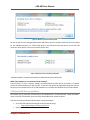
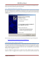
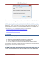
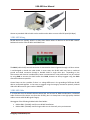
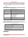
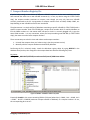
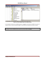
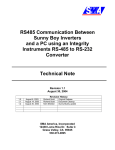
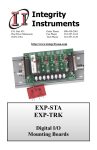
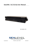
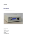
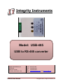
Integrity Instruments
Model: USB-485
USB to RS-485 converter
Integrity Instruments, Inc.
PO Box 451
2642 20th Ave SW
Pine River, MN 56474 USA
USB-485 User Manual
Order:
Tech:
Fax:
Web:
800-450-2001
218-587-3120
218-587-3414
www.integrityusa.com and www.rs-485.com
Copyright © 2011, Integrity Instruments, Inc.
USB-485 User Manual
Copyright
Copyright © 2011-2012, Integrity Instruments, Inc. All rights reserved.
No part of this manual may be reproduced, copied, or transmitted in any form or by any means without
the prior written permission of Integrity Instruments, Inc.
Acknowledgements
Microsoft Windows is a registered trademark of Microsoft Corporation.
All other trademarks and/or registered trademarks are the property of their respective owners.
Warranty
Integrity Instruments warranties select products against defective workmanship and components for the
life of the unit. Integrity Instruments agrees to repair or replace, at its sole discretion, a defective
product if returned to Integrity Instruments with proof of purchase. Products that have been misused,
improperly applied, or subject to adverse operating conditions fall beyond the scope of defective
workmanship and are not covered by this warranty.
Document:
Filename:
Revision:
Date:
USB-485 User Manual
USB-485 User Manual (1-6-2011).docx
1.00
January 6, 2012
Integrity Instruments, Inc.
ii
USB-485 User Manual
1
2
Table of Contents
Introduction .......................................................................................................................................... 1
Driver Installation.................................................................................................................................. 1
2.1
Windows 7 Driver Installation....................................................................................................... 1
2.2
Windows XP Driver Installation .................................................................................................... 2
2.2.1
Windows XP Manual Driver Installation ............................................................................... 4
2.3
Increasing Comport Numbers (Windows) .................................................................................... 4
2.4
Other Operating Systems (Linux, Mac OS, Embedded Windows, Windows, etc.) ....................... 6
3 Operation .............................................................................................................................................. 6
3.1
USB Cable ...................................................................................................................................... 6
3.2
RS-485 Wiring................................................................................................................................ 7
3.3
RS-485 Cable ................................................................................................................................. 7
3.4
LED Indicators ............................................................................................................................... 8
3.5
Termination Resistor ..................................................................................................................... 8
3.6
Using EZTerm ................................................................................................................................ 9
4 Specifications ...................................................................................................................................... 10
4.1
Electrical Protection Measures ................................................................................................... 10
5 Comport Number Registry Fix............................................................................................................. 11
Figures
Figure 1: USB-485 Converter ........................................................................................................................ 1
Figure 2: Windows 7 Automatic Driver Install .............................................................................................. 2
Figure 3: Windows 7 Driver Installation Completed ..................................................................................... 2
Figure 4: Windows XP FTDI Setup EXE Launch.............................................................................................. 3
Figure 5: FTDI setup executable MS-DOS window........................................................................................ 3
Figure 6: Windows XP New Hardware Wizard .............................................................................................. 4
Figure 7: Increasing comport numbers (COM6) ........................................................................................... 5
Figure 8: Uninstall comport to release assigned number ............................................................................. 6
Figure 9: RS-485 Connection Terminals ........................................................................................................ 7
Figure 10: LED indicators (left to right) RX / TX / PWR ................................................................................. 8
Figure 11: Termination resistor jumper (installed) ....................................................................................... 9
Figure 12: EZTerm used with USB-485 protocol converter .......................................................................... 9
Figure 13: REGEDIT "COM Name Arbiter" Key Name ................................................................................. 11
Figure 14: ComDB value COM1, COM3, COM4 and COM6 are allocated................................................... 12
Figure 15: ComDB value only COM1 remains (bit0) ................................................................................... 12
Figure 16: Corrected "COM Name Arbiter" with COM1 remaining ............................................................ 13
Tables
Table 1: LED Indicators.................................................................................................................................. 8
Table 2: USB-485 Converter Specifications................................................................................................. 10
Table 3: USB-485 Electrical Protection ....................................................................................................... 10
Integrity Instruments, Inc.
iii
USB-485 User Manual
1 Introduction
The Integrity Instruments USB-485 is a fully automatic USB to RS-485 protocol converter. It is a USB 2.0
compliant USB Full Speed device (12 Mbps) and is capable of handling multi-drop RS-485 serial
communications from 300 baud to 3M baud. The USB-485 is robust and reliable, yet easy to use.
The USB-485 converter behaves exactly like a standard RS-232 UART comport device in all supported
operating systems, so your legacy comport software stays exactly the same. In most cases the USB-485
converter is a simple drop-in replacement for your current RS-232 UART interface.
A new virtual UART comport is created when the USB-485 is plugged into the computer. In Windows this
is often COM3 and in Linux this is often /dev/ttyUSB0 (the exact ordinal number x of COMx and
/dev/ttyUSBx depends on the system configuration).
Figure 1: USB-485 Converter
More details about the operating parameters and specifications can be found in the Specifications
section later in this document.
2 Driver Installation
The Integrity Instruments USB-485 converter uses the FTDI FT232R chip which has excellent support for
USB device drivers in most common operating systems. All Microsoft Windows operating systems are
supported including Windows Embedded versions and Windows CE. Linux support has been included in
2.6.31 kernels and later so the driver is built-in. Also, Mac OS X is supported.
2.1 Windows 7 Driver Installation
You’re in luck! FTDI has released fully qualified WHQL drivers available through Microsoft.
Who cares? What does this mean?
The latest Microsoft certified drivers will be downloaded and installed automatically by Windows 7
when you plug in the USB-485 converter! The following screen capture shows the Windows 7 driver
installation dialog in action. Drivers for both x86 (32-bit) and x64 (64-bit) are automatically installed.
Integrity Instruments, Inc.
1
USB-485 User Manual
Figure 2: Windows 7 Automatic Driver Install
As you can see from the dialog windows above and below, there are actually two drivers that are loaded
for the USB-485 converter (i.e., FTDI FT232R chip): 1) the USB Serial Converter driver, and 2) the USB
Serial Port driver (which is the virtual comport driver VCP).
Figure 3: Windows 7 Driver Installation Completed
“Windows Update” retrieves the latest driver updates directly from Microsoft.
What if my computer is not connected to the Internet?
Are you living in a cave? Seriously though, we understand that there will be time when a computer
cannot be connected directly to the internet. The drivers still need to be obtained through the internet,
but that can be installed from a CD or USB thumb drive. Just follow the Windows XP instructions below.
2.2 Windows XP Driver Installation
The easiest way to install the FTDI VCP drivers for Windows XP is to download the “setup executable”
version from the FTDI website, then launch the executable which installs the driver.
Here are the steps to load the FTDI VCP driver “setup executable”:
•
•
Go to the FTDI website and navigate to the VCP Drivers page
o http://www.ftdichip.com/Drivers/VCP.htm
Download the Windows “setup executable”
Integrity Instruments, Inc.
2
USB-485 User Manual
•
•
o http://www.ftdichip.com/Drivers/CDM/CDM20814_Setup.exe
o The exact file name will change as FTDI releases new versions
o Save the file on your hard drive
Launch the setup executable previously saved
Attach the USB-485 converter. It should function immediately after the driver automatically
loads (since it was previously installed when the “setup executable” was launched).
Figure 4: Windows XP FTDI Setup EXE Launch
When you see the MS-DOS command window shown below, you know the FTDI “setup executable” ran.
Figure 5: FTDI setup executable MS-DOS window
Integrity Instruments, Inc.
3
USB-485 User Manual
Once the setup executable has been successfully executed, you can now plug in the USB-485 converter
and the driver will be automatically (and silently) installed.
2.2.1 Windows XP Manual Driver Installation
You can also download the driver package from FTDI, extract the driver to a location of your choosing,
then select “Install from a list or specific location (Advanced)” from the Hardware Wizard dialog when
plugging in the USB-485 converter for the first time and selecting the directory where the drivers were
extracted earlier.
Figure 6: Windows XP New Hardware Wizard
More information and step-by-step instructions can be found at FTDI website using the following URL:
http://www.ftdichip.com/Support/Documents/InstallGuides.htm
2.3 Increasing Comport Numbers (Windows)
If you use several different USB-485 converters or other products with the FTDI FT232R chip in it, you
may notice the phenomenon of increasing comport numbers. The issue of increasing comport numbers
is related to how many new and unique USB-485 devices that have been plugged into a computer
system. Windows will assign a new comport number each time a new USB-485 (or a new FTDI FT232R
USB/UART chip) is plugged into the system.
Since each USB-485 (and FT232R chip) has a unique serial number, Windows assigns a new comport
number to it when it is plugged into the computer to create a permanent association between USB
Integrity Instruments, Inc.
4
USB-485 User Manual
device and comport number. In the example below, the USB-485 converter was assigned COM6 even
though there are no other USB-485 or RS-232 comport devices currently plugged into the computer.
Figure 7: Increasing comport numbers (COM6)
Device manager can be launched by typing DEVMGMT.MSC into the Windows run/start launch box.
The device manager can be reached via the Windows Control Panel as well.
The issue of increasing comport numbers can be circumvented by uninstalling the USB-485 (or FT232R)
device before removing it. This is accomplished by right clicking on “USB Serial Port (COM6)” and
selecting “Uninstall”. Once it is uninstalled, the comport number can then be reused by another device.
Integrity Instruments, Inc.
5
USB-485 User Manual
Figure 8: Uninstall comport to release assigned number
There is also another method to remove the comport numbers through a manual registry edit process.
Please see Comport Number Registry Fix later in this manual.
2.4 Other Operating Systems (Linux, Mac OS, Embedded Windows, Windows, etc.)
Some operating systems like Linux have the FTDI drivers built right into the kernel. In that case, you
should be able to plug it in and you’re off and running immediately without any driver installation steps.
If you need support for other operating systems, please visit the FTDI website at:
http://www.ftdichip.com/Support/Documents/InstallGuides.htm
http://www.ftdichip.com/Drivers/VCP.htm
3 Operation
The USB-485 converter is very simple to use:
•
•
•
•
Plug the USB-485 into a PC or Laptop via a standard USB A-B cable
Load the drivers (exact steps dependent on the OS running on the PC or laptop)
Wire the RS-485 A/B communication lines to the RS-485 device network
Use it like a standard serial RS-232 comport that handles serial data from 300 to 3M baud
It’s fully automatic and will handle the RS-485 multi-drop drive enable for you as well as automatically
adjust to any baud rate to which you configure the comport.
3.1 USB Cable
The USB-485 uses the standard USB B connector and connects to a PC or Laptop with the common USB
A-B cable. See the pictures of the connector used by the USB-485 converter and the USB cable below
Integrity Instruments, Inc.
6
USB-485 User Manual
Almost any standard USB A-B cable can be used since the device runs are USB Full Speed (12 Mbps).
3.2 RS-485 Wiring
RS-485 devices are typically wired in a daisy chain fashion where all devices on the RS-485 network
backbone share the same RS-485 A and B data lines.
Figure 9: RS-485 Connection Terminals
The SHLD (cable shield) terminal connection is connected to electrical ground through a 10 ohm resistor
is and designed to handle the cable shield. In some cases, the RS-485 cable may have a combined
ground and shield connection through a braided shield or single drain wire. Depending on the
environment and electrical considerations, better communications noise performance may be realized
by using GND to connect the shield rather than SHLD, however we always suggest using the SHLD
connection whenever possible.
Ground loops can be a problem if there is a voltage difference in the grounding of different RS-485
devices connected together. In that case we suggest using the Integrity Instruments optically isolated
USB to RS-485 converter (part number USB-485I).
3.3 RS-485 Cable
It is imperative that the RS-485 cable be twisted pair and at least 24 AWG stranded wire. Unshielded
cable can be used for shorter runs (less than 50 feet), but it is always best to use high quality shielded
cable to ensure solid RS-485 signal integrity.
We suggest of the following shielded cable from Belden:
•
•
Belden 9841 (24 AWG) used for most RS-485 installations
Belden 9463 (20 AWG) used for longer cable runs in electrically noisy environments
Integrity Instruments, Inc.
7
USB-485 User Manual
3.4 LED Indicators
Three different LED indicator lights are present on the USB-485 converter. Their color and meaning is
listed in the table below.
Table 1: LED Indicators
LED Color
GREEN
RED
YELLOW
ALL ON CONTINUOUSLY
Meaning
Receive RS-485 data
Transmit RS-485 data
Unit power on (from USB)
USB bus is disconnected from the
PC/laptop, it is powered off, or in
suspend mode
The LED indicators for RS-485 Transmit and Receive are high-efficiency clear lens LED’s that will blink
briefly when RS-485 data is transferred. They have a narrow field of light, but are bright. The LED
indicator for Power is on continuously as long as there is power available on the USB bus.
Figure 10: LED indicators (left to right) – RX | TX | PWR
Receive:
Transmit:
Power:
When data is being received on the RS-485 line, the GREEN LED will flash on.
When data is being transmitted on the RS-485 lines, the RED LED will flash on.
When USB power is available, the YELLOW LED will be on continuously.
Note: If the USB-485 converter is connected to a powered USB hub, ALL three LED indicators will be ON
when the PC/Laptop is powered down, thus indicating the USB bus is not operating.
3.5 Termination Resistor
Integrity Instruments, Inc.
8
USB-485 User Manual
A termination resistor of 120 ohms can be enabled by simply using a jumper shunt on the JP1 pins
positioned next to the terminal strip. When the jumper shunt is installed (shown BELOW), the 120 Ω
termination resistor is enabled.
Figure 11: Termination resistor jumper (installed)
It is important that the first and last nodes each end of the RS-485 cable be terminated using a 120 ohm
resistor, especially for longer cable runs.
3.6 Using EZTerm
Ok, we got sick of dealing with programs like Hyper Terminal, so we wrote our own EzTerminal program.
You can download EZTerm from our website at: http://www.rs-485.com/downloads.asp
The nice thing about EZTerm is that you can reconfigure the comport settings on the fly, capture entire
serial terminal sessions, display data in raw hexadecimal mode, and the transmit and receive data is
color coded so you can better understand what data was sent by the PC and what data was received.
Figure 12: EZTerm used with USB-485 protocol converter
Integrity Instruments, Inc.
9
USB-485 User Manual
In the example above, the USB-485 converter was used to communicate with our 485M300 RS-485 data
acquisition module. Data in GREEN was received by the PC through the USB-485 (sent by the 485M300)
while data in RED was transmitted by the PC through the USB-485 protocol converter to the 485M300.
4 Specifications
Please see the USB-485 converter specifications table below:
Specification
Power Consumption
USB communications
RS-485 baud rate
Operating Temperature Range
Windows OS Support
Embedded Windows Support
Linux OS Support
Mac OS Support
Table 2: USB-485 Converter Specifications
Value
< 90 ma typical @ 5V powered from USB bus
250 ma max. @ 5V (RS-485 drives into a dead short)
USB 2.0 compatible Full Speed (12 Mbps)
300bps to 3Mbps (depends on the device driver for the
specific operating system used) Windows 7 = 921600bps
-40°C to 85°C
Legacy: Windows 98/98SE, 2K, and 2K3
Windows XP x86 and x64
Windows Vista x86 and c64
Windows Server 2008
Windows 7 x86 and x64
Windows XP Embedded
Windows CE 4.2, 5.0, and 6.0
2.4 and greater
Mac OS 8/9, OS-X
4.1 Electrical Protection Measures
There are several technical measures built into the USB-485 designed to protect the computer
equipment connected to the device as well as the USB-485 converter itself.
Table 3: USB-485 Electrical Protection
Electrical Protection Measures
Transient suppression on USB communication lines D+/D- and USB power VBUS
TVS avalanche diode (Little fuse SP0503BAHTG)
Transient suppression on the RS-485 data communication lines A/B
TVS avalanche diode (Little fuse SP0502BAHTG)
Current/voltage limiting resistors on RS-485 data communication lines A/B
These 10 ohm resistors also act as fuses if there is a catastrophic fault on the RS-485 data lines
such as 110 VAC bridging or short
Resettable fuse on USB power line VBUS limits current to the USB-485 at 500 ma
More information and details can be found on the USB-485 schematic online. See our website at:
http://www.rs-485.com/
Integrity Instruments, Inc.
10
USB-485 User Manual
5 Comport Number Registry Fix
If you’re lucky enough to use dozens of different USB-485 converters on the same machine, you may
have noticed that each time a new USB-485 converter (or, in fact, any device using the FFTDI FT232R
chip), the comport number continues to increase, even though you may only have one USB-485
currently connected to the PC. A progression of comport numbers such as COM3, COM4, COM5, etc.
keep building as new USB-485 converters are introduced.
The phenomenon is a simple artifact of Windows associating a specific USB-485 (or FTDI FT232R) with a
specific comport number. Each FTDI FT232R gets a unique serial number which is used by Windows to
link the COMx number to it. No matter what USB port or hub it is currently plugged into, it gets the
same COMx number. It is very convenient, unless you keep introducing new USB-485 (or FTDI FT232R
chips), but want to use the lower comport numbers.
There are two ways to solve this issue and release used comport numbers:
1. Uninstall the comport when you’re done using it (see the previous section)
2. Manually edit the comport database maintained by Windows
Performing the fix is relatively simply. Launch the Windows registry editor by typing REGEDIT in the
Windows start/run box, then navigate to the comport data base with the following key name:
Key Name:
HKEY_LOCAL_MACHINE\SYSTEM\CurrentControlSet\Control\COM Name Arbiter
Figure 13: REGEDIT "COM Name Arbiter" Key Name
Essentially ComDB is a bit vector containing 256 bits (32 bytes) where bit:0 = COM1, bit:1 = COM2, bit:2
= COM3 … bit:255 = COM256 (maximum comport number in Windows) If a comport number is in use,
the corresponding bit is set to 1.
Integrity Instruments, Inc.
11
USB-485 User Manual
In this example, ComDB is 0x2D = 00101101 binary where COM1, COM3, COM4, and COM6 are all
allocated for use and COM2 and COM5 are not allocated. However, when a new USB-485 is plugged in
COM7 will be used (as opposed to claiming the unused COM5 bit 4).
To free a comport number, simply delete the corresponding bit in binary value ComDB. The value
ComDB can be edited by either double clicking on it or selecting the Edit menu in REGEDIT.
Figure 14: ComDB value COM1, COM3, COM4 and COM6 are allocated
After removing the unused comport numbers, only COM1 remains (binary value 0x01);
Figure 15: ComDB value only COM1 remains (bit0)
Integrity Instruments, Inc.
12
USB-485 User Manual
Figure 16: Corrected "COM Name Arbiter" with COM1 remaining
In this example, the next time a USB-485 converter is plugged in, the OS will use COM3 for the new VCP
comport number. Note that COM1 and COM2 are reserved for the motherboard comport numbers.
Note: This is a manual registry edit operation which can be dangerous and possibly leave your computer
unbootable if incorrect modifications are made to key values other than ComDB
Integrity Instruments, Inc.
13