1
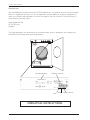
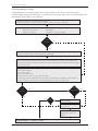
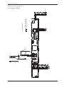
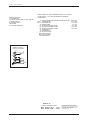
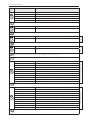
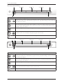
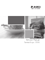
Service Manual
Tumble Dryer - TD70
Service Manual
Contents
Tumble Dryer TD70
Updates...................................................................................................................................................................................................................................................4
Introduction..........................................................................................................................................................................................................................................5
Troubleshooting strategy...............................................................................................................................................................................................................6
Product overview..............................................................................................................................................................................................................................7
Technical data.......................................................................................................................................................................................................................................9
Component descriptions........................................................................................................................................................................................................... 10
Components and measurement values....................................................................................................................................................................... 10
Components and function description......................................................................................................................................................................... 12
Control unit....................................................................................................................................................................................................................................... 16
Circuit diagram TD70.1......................................................................................................................................................................................................... 16
Circuit diagram TD70.2......................................................................................................................................................................................................... 18
Circuit diagram TD70.2 HP................................................................................................................................................................................................. 20
Circuit diagram TD70.2 HWC.......................................................................................................................................................................................... 22
Circuit diagram TD70.3......................................................................................................................................................................................................... 24
Troubleshooting............................................................................................................................................................................................................................... 26
Fault indicators TD70.1.......................................................................................................................................................................................................... 26
Fault indicators TD70.2.......................................................................................................................................................................................................... 27
Fault indicators TD70.3.......................................................................................................................................................................................................... 29
Other faults.................................................................................................................................................................................................................................. 30
Service menu and settings......................................................................................................................................................................................................... 32
Service menu TD70.1............................................................................................................................................................................................................. 32
Service menu TD70.2............................................................................................................................................................................................................. 34
Service menu TD70.3............................................................................................................................................................................................................. 36
Settings............................................................................................................................................................................................................................................ 38
Activating heating element 2 TD70.1 ..................................................................................................................................................................... 38
Activating heating element 2 TD70.2 ..................................................................................................................................................................... 38
Activating heating element 2 TD70.3 ..................................................................................................................................................................... 38
Store program....................................................................................................................................................................................................................... 38
Service and installation
Removing top plate and rear panel .............................................................................................................................................................................. 39
Replacing the panel and the control unit .................................................................................................................................................................. 41
Transporting a tumble dryer with a heat pump .................................................................................................................................................... 43
Service Manual TD70
Updates
Rev
Date
Description
Initials
01
2011-09-06
First version
FH
02
2011-10-03
BRAND OTHER included
FH
03
2011-10-20
New document structure
FH
04
2012-01-20
New revision circuit diagram
EH
05
2012-05-03
Changed the info about Autofilter
BPA
06
2012-05-04
Updated part no control units, irrelevant articles deleted.
EH
07
2012-07-05
Troubleshooting TD70 HP, LCD F29, removing back rear included.
EH
4
Service Manual TD70
Introduction
You are holding the service manual for TD70 tumble dryers. It should be easy to service a tumble
dryer. It is important that you, as a service technician, are provided the necessary conditions to
work in an efficient and satisfactory manner. Our hope is that this Service & Training Guide is a
useful tool for your daily work.
Asko Appliances AB
SE-534 82 Vara
Sweden
The type designation can be found on the machine plate, which is located on the inside of the
front panel by the door catch (see image below).
Type designation
Product number
TYPE TD70.3
Year Week Serial number
OPERATING INSTRUCTIONS
Always have the operating instructions for the machine available during service
5
Service Manual TD70
Troubleshooting strategy
Troubleshooting is an important part of the service callout, and as such we have drawn up a
troubleshooting strategy that describes, in broad terms and step by step, what you need to do to find
and diagnose faults arising in our machines.
• Ask the customer to describe the problem.
• Check whether the customer’s description matches the reported fault.
• Check that the machine is correctly installed:
- Electrical connection
- Drainage
- Water connection
- Machine correctly levelled
Fault
found?
No
Yes
Incorrect installation or external factors that affect performance and functionality (for
example, water pressure, electrical supply, drainage).
The machine operates normally. No deviations can be found. The customer probably
needs to be informed about proper use of the machine. If necessary, also inform the
customer about the warranty conditions and the fact that the customer will be charged
for the service call.
Open the service menu:
1. Check the settings
2. Run a test cycle
3. Note any fault codes
If the above actions do not uncover the fault:
• Conduct general troubleshooting. Use the documentation available at ServiceSaver
(service manuals, service memos, wiring diagrams and other documents).
Fault
found?
No
Fault
diagnosed?
Yes
Yes
Yes
OK?
No
Repair and check
function/safety.
Contact technical support
for assistance.
Carry out the actions
suggested by technical
support.
Satisfied customer!
6
No
Service Manual TD70
Product overview
TD70.1, Paneltype A - (BRAND ASKO)
S1
S4
S7
S11
J1
Programs:
4
Options:
2
Settings:
1
S10
TD70.1, Paneltype B - (BRAND ASKO)
S7
S11
/
S1
J1
Programs:
6
Options:
5
Settings:
1
S3
S4
TD70.1 - (BRAND OTHER)
S1
6
Options:
5
Settings:
1
S3
TD70.2 - (BRAND ASKO)
S1
J1
Programs:
6-15
Options:
5
Settings:
1
S4
S2 S3
DISPLAY
S10
S7
J1
Programs:
S9
S11
S9
S10
S8
S9
S4 S5 S6 S7
7
Service Manual TD70
Product overview
TD70.2 - (BRAND OTHER)
S1
J1
Programs:
6-15
Options:
5
Settings:
1
TD70.3
S1
DISPLAY
DISPLAY1
S2 S3
S8
S9
S4 S5 S6 S7
DISPLAY2
DISPLAY3
J1
S3
S2
Programs:
10, plus settings menu
Options:
5
Settings:
4
TD70.3 (Integrerad)
S4
S1
DISPLAY1
S5
S3
DISPLAY3
S2
Programs:
10, plus settings menu
Options:
5
Settings:
4
8
DISPLAY2
Service Manual TD70
Technical data
Technical information
Height
850 mm
Width
595 mm
Depth
585 mm
Weight
43 kg (Vented)
47 kg (Condenser)
55 kg (Heat pump)
44 kg (Heating Water Circuit)
Cylinder volume
112 litres
Capacity
EU 7.0 kg
US/AU 7.0 kg
Speed
50-55 rpm
Connection
1-phase 230 V, 50/60 Hz, (10 A/16 A) **
Rated power
1950 W = 10 A** (Vented/Condenser)
3000 W = 16 A** (Vented)
2500 W = 16 A** (Condenser)
1300 W = 10 A** (Heat pump)
1950 W = 10 A** (Heating Water Circuit)
The control buttons are used to switch between 10 A and 16 A via the software.
Does not apply to Heat Pump or Heating Water Circuit.
Drum material
Stainless steel
Outer panels
Powder-coated and hot-galvanised sheet steel or stainless steel
Installation
Stacked or freestanding
Protection class
IP X4
** See type plate.
Energy consumption and program times
See the operating instructions for information on energy consumption and program times.
9
Service Manual TD70
Component description
Components and measurement values
The specified resistance values apply at room temperature (about 20°C/68°F). Values within
±10% are considered normal.
Article no. Component
Measurement value
Comment
80 839 15
Motor 50 Hz,
220/240 V
80 839 16
Motor 60 Hz,
220/240 V
The motor is a 2-pin motor and is
directly connected to the fan for
internal air and the gearing for driving
the cylinder. On condenser dryers, the
motor also drives the fan for external air.
80 903 13
80 903 14
80 902 70
80 821 28
80 846 48
80 762 02
Capacitor
Capacitor
Capacitor heat pump
Condensate pump
Condensate pump
EMC-filter with inductor
Winding resistance:
cable colour red-white 26.5 Ω
cable colour red-blue 53.5 Ω
cable colour white-blue 27.0 Ω
Current: 0.7 A; 140 W; 2850 rpm
Winding resistance:
cable colour red-white 26.5 Ω
cable colour red-blue 53.5 Ω
cable colour white-blue 27.0 Ω
Current: 0.7 A; 140 W; 3300
rpm
8 μF
6 μF
17 μF
80 833 44
Thermistor
4.8 kΩ (at 25°C)
80 902 72
80 902 73
80 902 24
80 761 04
Termostat 150
Termostat 135
Thermostat 110
Door switch
150°C manual reset
135°C manual reset
110°C automatic
10
50 Hz
60 Hz
50 and 60 Hz
50 Hz
60 Hz
The filter eliminates interference to and
from the machine.
The thermistor controls temperature
regulation. If the thermistor is shortcircuited or detaches from the control
unit, the program is stopped.
The thermostat/overheating cut-out
stops the program if the temperature
becomes too high.
The front door triggers a door switch
which stops the program when the door
is open. If the door has been opened and
closed during the program the machine
must be restarted using the Start/Stop
button.
Service Manual TD70
Component description
Article no. Component
80 761 03
Microswitch float
Overflow guard
80 824 92
80 915 90
Heating element 1950 W
Heating element 2500
W
Heating element 3000
W
Base heat pump
complete
Base heat pump
complete
Reversing valve
Control unit compl.
TD70.1 A
Control unit compl.
TD70.1 B
Control unit complete
TD70.2
Control unit complete
TD70.2 HP/HWC
Control unit complete
TD70.3
Control unit complete
TD70.3 FI
LED-light compl.
80 824 91
80 821 22
80 821 23
80 88 415
88 015 18
88 015 19
88 015 20
88 015 21
88 015 00
88 015 01
80 846 49
Measurement value
Comment
If both containers in the tumble dryer
are full the program is stopped by a float
switch installed in the lower container.
“Over flow” is indicated on the display.
Heater 1: 1950 W, 24.5 Ω
Heater 1: 1950 W, 24.5 Ω
Heater 2: 550 W, 91.4 Ω
Heater 1: 1950 W, 24.5 Ω
Heater 2: 1050 W, 45.5 Ω
50 Hz
60 Hz
1.9 kΩ
The control unit contains
microprocessors for controlling
programs, the motor, the heating
elements etc.
LED-technology for the machine’s
internal light.
11
Service Manual TD70
Component descriptions
Components and function description
Here we describe the function and
specification of the most important
components. Certain components are found
only in more highly specified machines or in
particular markets. See the Troubleshooting
chapter for fault and information codes.
CU (Control Unit)
The CU (Control Unit) functions as both a
control panel and a logic component. The
control panel is equipped with knobs/buttons
for selecting programs, Start/Stop buttons and
a display. It is an integrated part of the CU
and cannot be replaced separately. The logic
component manages functions needed for
drying programs and diagnosis. The CU has an
internal power supply for the logic component.
In the event of a fault, the CU can diagnose
a number of components and functions, and
a total of 4 fault codes can be displayed. To
facilitate troubleshooting there is a component
testing function in which the outputs are
activated according to a special sequence.
Power supply
Mains voltage, built-in internal voltage
converter for the logic component.
Thermistors
The thermistors are of the NTC type (Negative
Temperature Coefficient), which means their
resistance decreases as temperature increases.
Thermistor 1 is in the air duct on the front frame,
after the internal impeller. If there is an interruption
in the thermistor circuit or if it short circuits, the
drying program stops and the display shows
“Thermistor fault”.
Purpose: Measures the temperature of the air that
has passed the load and controls the drying process
and the heating element.
Thermistor 2 is on condenser dryers located after the
condenser and on heat pump dryers located on the
evaportator pipe by the comperssor. Purpose: Measures the temperature of the
dehumidified air, the value of which is used as a
parameter in the drying process.
Resistance values for thermistors 1 and 2
Temperature
Light
Certain machines have an internal light
that is activated when the door is opened.
LED technology is used to improve energy
efficiency.
12
Resistance
20°C
5989
25°C
4869
30°C
3946
35°C
3197
40°C
2598
45°C
2126
50°C
1758
55°C
1471
60°C
1240
65°C
1043
70°C
857
Tolerance: ±1%
Service Manual TD70
Component descriptions
Thermostat
Reset
Overheating cut-out
EMC filter
The filter is installed next to the cable fasteners
where the connection cable enters the
machine. The filter consists of a number of coils,
condensers and resistors.
Purpose: To eliminate electromagnetic
interference to and from the machine.
Overflow guard
The overflow guard comprises a microswitch
triggered by a float. When the lower condensed
water container becomes full the float rises and
triggers the microswitch. The microswitch is
normally closed; when activated it opens the
circuit. When the microswitch has been open
for more than 30 seconds, the drying program
stops and the display shows “Over flow”. You
can erase this message by turning the program
selector or pressing the Start/Stop buttons.
Purpose: To provide protection from any
water leaks or flooding from the machine.
Co
ver
pla
te
(65
8x
48
3m
m)
Thermostat and overheating cut-out
The thermostat is installed next to the heating
element and is used to reduce the element output
by turning it off if the ambient temperature
exceeds 135°C (±5°C) for condenser dryers and
110°C (±5°C) for others.
The machine is equipped with a overheating
cut-out, which is available in two versions, one
automatically resettable and one manual. The
overheating cut-out switches off the power supply
to all components if the temperature exceeds
150°C (±5°C) and closes the circuit once the
temperature drops below 135°C (±8°C). The
drying program stops and must be restarted if the
overheating cut-out is triggered.
To reset the manual overheating cut-out,
the cover plate on the machines back must be
removed. Press the button on the overheating cutout for manual reset. The automatic overheating
cut-out resets when the temperature drops below
135°C (±8°C) for condenser dryer and 120°C
(±5°C) for others.
Purpose: The thermostat measures
temperature and controls heating element
output. The overheating cut-out controls the
temperature and cuts the power supply if the
machine overheats.
13
Service Manual TD70
Component descriptions
Door switch
The door switch is located in a holder in the
middle of the front support and is activated by
a pin in the front door. The switch is normally
open and closes when the door is closed. If the
front door is opened during operation the CU
stops the drying program. The program starts
from the beginning if restarted.
Purpose: To prevent the machine from running
while the door is open.
Drainage pump (condenser dryer)
The drainage pump is located in the lower
condensed water container. The condensed
water is pumped to the condensed water
container or directly to the drain. When a
drying program is running, the drainage pump
is activated constantly in cycles of 30 seconds
ON and 210 seconds OFF.
Purpose: To pump condensed water to the
condensed water container or the drain.
Drying motor
The motor is at the bottom and drives the
impeller that is directly fitted to the shaft
journal. The motor is a unit with a belt
tensioner and springs and drives the drying
drum via a poly V-belt.
Purpose: To drive the impeller and drum during
the drying process.
Heating element
The heating element is located in the rear section
and consists of two separate heating coils. Each
heating coil is made from resistance wire.
Purpose: To heat the drying air to the right
temperature.
14
Service Manual TD70
Component descriptions
Heat pump (HP)
Certain types of machine are fitted with heat
pump systems. These systems are closed
circuits that are replaced by replacing the
machine’s base plate with a new module.
The function settings are adjusted in the
service menu.
2
1B
1A
Heating Water Circuit (HWC)
A certain type of machine is adapted for
connection to the building’s existing heated
water supply (such as district heating) to
reduce energy consumption.
The function settings are adjusted in the
service menu.
Evaporator filter and Auto filter
for Heat pump (HP)
Tumble dryers with heat pump are fitted with
evaporator filter containing a net filter (1A)
and a foam filter (1B). Some dryers can also be
fitted with auto filter, which consists of a water
filter (2), that is located under the condensed
water container.
15
Service Manual TD70
Programs and control unit
Circuit diagram TD70.1
CABLE POSITIONS
1: THERMISTOR
4: MOTOR, DRAIN PUMP, FLOAT SWITCH
5: DOOR SWITCH
8: POWER
9: HEATING ELEMENT
WIRES IN ALL MACHINES
WIRES IN SOME MACHINES
*A CONDENSE DRYER
DB
S
INKB
MO
L
F
EL 550W/1050W
T1
T2
EL 1950W
SE
TU
WA
HO
TU
PR
PR
RO
PR
M
AP *A
FB *A
CONNECTION BOX
FOR USA & CANADA
L1 2
L
L1 2
L
RECL
N
L
16
L2 2
L2 2
RECL
N
RECG
INKB
N
TO
TU
WA
HO
TU
NTC 2 *A
NTC 1
Service Manual TD70
RESISTANCES AT ROOM TEMPERATURE (CA. 20°C/68°F)
VALUES WITH +/-10% ARE REGARDED AS NORMAL
COMPONENT
AT SWITCH
F: RADIO INTERFERENCE SUPPRESSION FILTER 680K Ohm
NTC 1: THERMISTOR 1
4 - 6 K Ohm
NTC 2: THERMISTOR 2:
4 - 6 K Ohm
AP: DRAIN PUMP:
111 Ohm
EL: HEATING ELEMENT 550W
91.4 Ohm
EL: HEATING ELEMENT 1050W
45.3 Ohm
EL: HEATING ELEMENT 1950W
20.5 Ohm
MO: MOTOR
T1: THERMOSTAT, OVERHEATING
T2: THERMOSTAT, OVERHEATING
FB: FLOAT SWITCH
DB: DOOR SWITCH
ES
INES
S3
S4
S1
S7
S9
S10 S11
TOTAL RESET
TURN OFF POWER (S1)
WAIT FOR AT LEAST 5 SEC
HOLD STOP (S11)
TURN ON POWER (S1)
SERVICE MENU
TURN OFF POWER (S1)
WAIT FOR AT LEAST 5 SEC
HOLD S10
TURN ON POWER (S1)
PRESS S10 5 TIMES TO ENTER SERVICE MENU
PRESS STOP (S7) TO CHANGE MENU STEP
ROTATE DIAL TO CHANGE IN STEP
PRESSING START (S10) STORES AND EXITS SERVICE MENU
2012-01-11
CIRCUIT DIAGRAM TD70.1
80 902 52-01
This document must not be copied without
our written pemission, and the contents
thereof must not be imparted to a third party
nor be used for any unauthorized purpose.
Contravention will be prosecuted.
Asko Appliances AB
17
Service Manual TD70
Programs and control unit
Circuit diagram TD70.2
RES
CABLE POSITIONS
VALU
CABLE POSITIONS
1: THERMISTOR
COM
1: THERMISTOR
4: MOTOR, DRAIN PUMP,
FLOAT SWITCH
5: DOOR SWITCH 4: MOTOR, DRAIN PUMP, FLOAT
NTC
7: INTERIOR LIGHT 5: DOOR SWITCH
7: INTERIOR LIGHT
NTC
8: POWER
8: POWER
A
9: HEATING ELEMENT
9: HEATING ELEMENT
E
NTC 1
L1 2
L2 2
L2 2
NTC 2 *A
BE
BE
S1
SERVICE M
TURN OFF
WAIT FOR A
HOLD S2 O
TURN ON P
PRESS S2 O
EL 1950W
T2
EL 550W/1050W
T2
PRESS STO
ROTATE DI
PRESSING
EL 1950W
EL 550W/1050W
T1
NECTION BOX
USA & CANADA
L1 2
NTC 1
NTC 2 *A
E
E
WIRES IN ALL MACHINES
MO
WIRES IN ALL MACHINES
WIRES IN SOME MACHINES
T
WIRES IN SOME MACHINE
T
*A CONDENSE DRYER
F
*A CONDENSE DRYER
D
B
L
RECL
MO
CONNECTION BOX
FOR USA & CANADA
L1 2
L
L1 2
L
N
FT1
INKB
L
MO
RECL
DB
DB
RECL
FB *A
FB *A
AP *A
AP *A
M
M
STEP 1: PR
STEP 2: FAI
N
STEP 3: CO
F
L
TOTAL RES
INKB
TURN OFF
WAIT FOR A
HOLD STOP
TURN ON P
N
RECL
L
N
RECG
INKB
18
L2 2
L2 2
N
RECG
INKB
8
Service Manual TD70
RESISTANCES AT ROOM TEMPERATURE (CA. 20°C/68°F)
VALUES WITH +/-10% ARE REGARDED AS NORMAL
COMPONENT
FLOAT SWITCH
F: RADIO INTERFERENCE SUPPRESSION FILTER 680K Ohm
NTC 1: THERMISTOR 1
4 - 6 K Ohm
NTC 2: THERMISTOR 2:
4 - 6 K Ohm
AP: DRAIN PUMP:
111 Ohm
EL: HEATING ELEMENT 550W
91.4 Ohm
EL: HEATING ELEMENT 1050W
45.3 Ohm
EL: HEATING ELEMENT 1950W
20.5 Ohm
MO: MOTOR
T1: THERMOSTAT
T2: THERMOSTAT
FB: FLOAT SWITCH
DB: DOOR SWITCH
BE: INTERIOR LIGHT
CHINES
MACHINES
S1
S8 S9
S2 S3
SERVICE MENU
TURN OFF POWER (S1)
WAIT FOR AT LEAST 5 SEC
HOLD S2 OR S3
TURN ON POWER (S1)
PRESS S2 OR S3 3 TIMES TO ENTER SERVICE MENU
PRESS STOP (S9) TO CHANGE MENU STEP
ROTATE DIAL TO CHANGE IN STEP
PRESSING START (S8) STORES AND EXITS SERVICE MENU
N
L
STEP 1: PRODUCT DATA
STEP 2: FAILURE DATA
STEP 3: COMPONENT TEST
TOTAL RESET
TURN OFF POWER (S1)
WAIT FOR AT LEAST 5 SEC
HOLD STOP (S9)
TURN ON POWER (S1)
2012-01-11
CIRCUIT DIAGRAM TD70.2
80 902 54 - 01
This document must not be copied without
our written pemission, and the contents
thereof must not be imparted to a third party
nor be used for any unauthorized purpose.
Contravention will be prosecuted.
Asko Appliances AB
19
Service Manual TD70
Programs and control unit
Circuit diagram TD70.2 HP
RES
12
2
22
NTC 1
NTC 2
NTC 2
NTC 3
NB
NB
B
WIRES IN ALL MACHINES WIRES IN ALL MACHI
N
WIRES IN SOME MACHINES
WIRES IN SOME MACC
S
F
NTC 3
BE
BE
S1
SERVICE M
TURN OFF
WAIT FOR
HOLD S2 O
TURN ON P
PRESS S2
FA
FA
SP
SP
SV
SV
CO
CO
SH
SH
PRESS ST
ROTATE D
PRESSING
CONNECTION BOX
FOR USA & CANADA
L1 2
L
L
RECL
L1 2
CO
L
MO
INKB
F
L
CO
DB
RECL
STEP 1: PR
STEP 2: FA
STEP 3: CO
N
F
ECTION BOX
SA & CANADA
12
NTC 1
CABLE POSITIONS
CABLE POSITIONS
VAL
1: THERMISTOR
1: THERMISTOR
CO
2: THERMISTOR, LEVEL2:SWITCH
THERMISTOR, LEVEL SW
3: STEAM PUMP, SWITCHING
3: STEAM
VALVE
PUMP, SWITCHI
4: MOTOR, DRAIN PUMP,
4: FLOAT
MOTOR,
SWITCH
DRAIN PUMP,
F
NTC
NTC
5: DOOR SWITCH
5: DOOR SWITCH
NTC
5: COOLING FAN
5: COOLING FAN
7: INTERIOR LIGHT
7: INTERIOR LIGHT
M
8: POWER
8: POWER
F
9: STEAM HEATER, COMPRESSOR
9: STEAM HEATER, COMPR
D
MO
DB
TOTAL
INKB RES
TURN OFF
WAIT FOR
HOLD STO
TURN ON P
N
RECL
N
RECG
INKB
20
L
L2 2
L2 2
RECL
N
RECG
INKB
FB
FB
AP
AP
M
M
8
Service Manual TD70
EL SWITCH
TCHING VALVE
MP, FLOAT SWITCH
OMPRESSOR
MACHINES
E MACHINES
RESISTANCES AT ROOM TEMPERATURE (CA. 20°C/68°F)
VALUES WITH +/-10% ARE REGARDED AS NORMAL
COMPONENT
F: RADIO INTERFERENCE SUPPRESSION FILTER 680K Ohm
NTC 1: THERMISTOR 1
4 - 6 K Ohm
NTC 2: THERMISTOR 2
4 - 6 K Ohm
NTC 3: THERMISTOR 3
61 K Ohm
AP: DRAIN PUMP:
111 Ohm
MO: MOTOR
FB: FLOAT SWITCH
DB: DOOR SWITCH
BE: INTERIOR LIGHT
NB: LEVEL REED SWITCH
CO: COMPRESSOR
SV: SWITCHING VALVE
1.9 K Ohm
FA: COOLING FAN
637 Ohm
SP: STEAM PUMP
2.15 M Ohm
SH: STEAM HEATER
68 Ohm
S1
S8 S9
S2 S3
SERVICE MENU
TURN OFF POWER (S1)
WAIT FOR AT LEAST 5 SEC
HOLD S2 OR S3
TURN ON POWER (S1)
PRESS S2 OR S3 3 TIMES TO ENTER SERVICE MENU
PRESS STOP (S9) TO CHANGE MENU STEP
ROTATE DIAL TO CHANGE IN STEP
PRESSING START (S8) STORES AND EXITS SERVICE MENU
F
N
L
STEP 1: PRODUCT DATA
STEP 2: FAILURE DATA
STEP 3: COMPONENT TEST
TOTAL RESET
TURN OFF POWER (S1)
WAIT FOR AT LEAST 5 SEC
HOLD STOP (S9)
TURN ON POWER (S1)
2011-05-24
CIRCUIT DIAGRAM TD70.2 HP
80 902 56 - 00
This document must not be copied without
our written pemission, and the contents
thereof must not be imparted to a third party
nor be used for any unauthorized purpose.
Contravention will be prosecuted.
Asko Appliances AB
21
Service Manual TD70
Programs and control unit
Circuit diagram TD70.2 HWC
CABLE POSITIONS
1: THERMISTOR
4: MOTOR
5: SOLENOID VALVE
5: DOOR SWITCH
7: INTERIOR LIGHT
8: POWER
9: HEATING ELEMENT
NTC 1
RESIST
VALUES
COMPO
F:
NTC 1:
NTC 2:
EL:
MO: M
T1:
T2:
DB:
BE:
MV:
WIRES IN ALL MACHINES
WIRES IN SOME MACHINES
NTC 2
BE
S1
Relay board
SERVICE M
TURN OFF
WAIT FOR A
HOLD S2 O
TURN ON P
PRESS S2 O
MV
PRESS STO
ROTATE DI
PRESSING
T2
1950 W
T1
F
MO
INKB
N
L
STEP 1: PR
STEP 2: FAI
STEP 3: CO
TOTAL RES
TURN OFF
WAIT FOR A
HOLD STOP
TURN ON P
DB
M
CI
8
22
Service Manual TD70
RESISTANCES AT ROOM TEMPERATURE (CA. 20°C/68°F)
VALUES WITH +/-10% ARE REGARDED AS NORMAL
COMPONENT
F: RADIO INTERFERENCE SUPPRESSION FILTER 680K Ohm
NTC 1: THERMISTOR 1
4 - 6 K Ohm
NTC 2: THERMISTOR 2
4 - 6 K Ohm
EL: HEATING ELEMENT 1950W
20.5 Ohm
MO: MOTOR
T1: THERMOSTAT
T2: THERMOSTAT
DB: DOOR SWITCH
BE: INTERIOR LIGHT
MV: MAGNETIC VALVE
866 Ohm
ACHINES
MACHINES
S1
S8 S9
S2 S3
SERVICE MENU
TURN OFF POWER (S1)
WAIT FOR AT LEAST 5 SEC
HOLD S2 OR S3
TURN ON POWER (S1)
PRESS S2 OR S3 3 TIMES TO ENTER SERVICE MENU
PRESS STOP (S9) TO CHANGE MENU STEP
ROTATE DIAL TO CHANGE IN STEP
PRESSING START (S8) STORES AND EXITS SERVICE MENU
F
N
L
STEP 1: PRODUCT DATA
STEP 2: FAILURE DATA
STEP 3: COMPONENT TEST
TOTAL RESET
TURN OFF POWER (S1)
WAIT FOR AT LEAST 5 SEC
HOLD STOP (S9)
TURN ON POWER (S1)
2011-05-24
CIRCUIT DIAGRAM TD70.2 HWC
80 902 57 - 00
This document must not be copied without
our written pemission, and the contents
thereof must not be imparted to a third party
nor be used for any unauthorized purpose.
Contravention will be prosecuted.
Asko Appliances AB
23
24
L
N
L
L2 2
L2 2
L1 2
L1 2
N
RECG
INKB
RECL
RECL
L
CONNECTION BOX
FOR USA & CANADA
*A
FB
MO AP
T1
3
6
4
5
F
N
T2
EL
550W/
1050 W
TB
EL
1950 W
80 902 62 - 02
CIRCUIT DIAGRAM TD70.3
2012-01-11
BE DB
WIRES IN ALL MACHINES
WIRES IN SOME MACHINES
*A CONDENSE DRYER
NTC 2 *A
This document must not be copied without
our written pemission, and the contents
thereof must not be imparted to a third party
nor be used for any unauthorized purpose.
Contravention will be prosecuted.
Asko Appliances AB
NTC 1
F: RADIO INTERFERENCE SUPPRESSION FILTER 680K Ohm
NTC 1: THERMISTOR 1
4 - 6 K Ohm
NTC 2: THERMISTOR 2:
4 - 6 K Ohm
AP: DRAIN PUMP:
111 Ohm
EL: HEATING ELEMENT 550W
91.4 Ohm
EL: HEATING ELEMENT 1050W
45.3 Ohm
EL: HEATING ELEMENT 1950W:
20.5 Ohm
T1: THERMOSTAT
T2: THERMOSTAT
FB: FLOAT SWITCH
DB: DOOR SWITCH
MO: MOTOR PUMP
TB: MAIN SWITCH
Circuit diagram TD70.3
*A
MO
INKB
L
CABLE POSITIONS
1: THERMISTOR
4: MOTOR, DRAIN PUMP, FLOAT SWITCH
5: DOOR SWITCH
5: INTERIOR LIGHT
TB: POWER
EL: HEATING ELEMENT
RESISTANCES AT ROOM TEMPERATURE (CA. 20°C/68°F)
VALUES WITH +/-10% ARE REGARDED AS NORMAL
COMPONENT
Service Manual TD70
Programs and control unit
5
6
Service Manual TD70
T2
T1
CABLE POSITIONS
1: THERMISTOR
4: MOTOR, DRAIN PUMP, FLOAT SWITCH
5: DOOR SWITCH
5: INTERIOR LIGHT
TB: POWER
EL: HEATING ELEMENT
N
3
N6
TB
T2
EL
550W/
1050 W
3
6
TB
EL
550W/
1050 W
EL
1950 W
RESISTANCES AT ROOM TEMPERATURE (CA. 20°C/68°F)
VALUES WITH +/-10% ARE REGARDED AS NORMAL
COMPONENT
F: RADIO INTERFERENCE SUPPRESSION FILTER 680K Ohm
NTC 1: THERMISTOR 1
4 - 6 K Ohm
NTC 2: THERMISTOR 2:
4 - 6 K Ohm
AP: DRAIN PUMP:
111 Ohm
EL: HEATING ELEMENT 550W
91.4 Ohm
EL: HEATING ELEMENT 1050W
45.3 Ohm
EL: HEATING ELEMENT 1950W:
20.5 Ohm
T1: THERMOSTAT
RESISTANCES AT ROOM TEMPERATURE (CA. 20°C/68°F)
T2: THERMOSTAT
VALUES WITH +/-10% ARE REGARDED AS NORMAL
FB: FLOAT SWITCH
CABLE POSITIONS
COMPONENT
DB:
DOOR SWITCH
1: THERMISTOR
MO: MOTOR PUMP
4: MOTOR, DRAIN PUMP, FLOAT SWITCH
F: RADIO INTERFERENCE SUPPRESSION FILTER 680K Ohm
TB: MAIN SWITCH
5: DOOR SWITCH
NTC 1: THERMISTOR 1
4 - 6 K Ohm
5: INTERIOR LIGHT
NTC 2: THERMISTOR 2:
4 - 6 K Ohm
TB: POWER
AP: DRAIN PUMP:
111 Ohm
EL: HEATING ELEMENT
EL:
HEATING ELEMENT
91.4 Ohm
CONDENSE
DRYER 550W
*A
*A *A
EL: HEATING ELEMENT 1050W
45.3 Ohm
EL
EL: HEATING ELEMENT 1950W:
20.5 Ohm
1950 W
T1: THERMOSTAT
WIRES IN ALL MACHINES
T2: THERMOSTAT
WIRES IN SOME MACHINES
MO AP FB:
FBFLOAT
SWITCH
CONNECTION BOX
DB:
DOOR
SWITCH
FOR USA & CANADA
MO: MOTOR PUMP
L1 2
TB: MAIN SWITCH
L
L
T2
EL
550W/
1050 W
L1 2
RECL
N
EL
L
1950 W
*A CONDENSE DRYER
L2 2
L2 2
RECL
N
RECG
INKB
WIRES IN ALL MACHINES
WIRES IN SOME MACHINES
NTC 1
NTC 2 *A
NTC 1
NTC 2 *A
BE DB
2012-01-11
DIAGRAM TD70.3
BECIRCUIT
DB
80 902 62 - 02
This document must not be copied without
our written pemission, and the contents
thereof must not be imparted to a third party
nor be used for any unauthorized purpose.
Contravention will be prosecuted.
Asko Appliances AB
2012-01-11
CIRCUIT DIAGRAM TD70.3
80 902 62 - 02
This document must not be copied without
our written pemission, and the contents
thereof must not be imparted to a third party
nor be used for any unauthorized purpose.
Contravention will be prosecuted.
Asko Appliances AB
25
Service Manual TD70
Troubleshooting
Fault indicators TD70.1
In the case of a fault the following fault indicators are shown.
L4
Panel type A
L7
Auto Dry
S4
S7
Auto Normal Dry
S11
L35
T 7 4 3 C
S1
L3
L2
J1
L9
L34
L32
Auto Iron Dry
Auto Extra Dry
L33
L8
L24
L29
B U T T E R F L Y
L37 S10
D R Y I N G
L36
Indication
Cause
Action
The light to the left of the
Start button flashes
The microswitch is opened when a
full condensed water tank is detected.
Detection begins 30 seconds after the
program starts. If the microswitch is open
>30 seconds the program cycle is stopped.
Check whether the customer has:
• Emptied the tank and restarted the machine.
Service action:
• Clean hoses and check drainage pump
voltage and resistance.
• Check that the float has not got “stuck” and
check the function of the microswitch.
The light above the Start
button flashes
The program cycle time exceeds 200
minutes. The cycle is stopped and the
program is reset.
High ambient temperature combined
with low heater output and low drying
temperature leads to poor condensation
formation.
Poor condensation due to blocked
external air
Check whether the customer has:
• Tried spinning at a higher speed.
• Had the machine switched off for 30 minutes
before restarting.
• Good ventilation in the room.
Service action:
• Ensure that the external air has free passage.
After carrying out corrective actions as above, reset the fault indication on the display by switching off the machine
at the main power switch.
Panel type B
L4
L7
S3
S4
L31
S7
LCD
S11
/
S1
LCD
L3
L2
J1
L9
L8
L18
L24
Cause
L29
S9
S10
Action
F10 is shown on the display The microswitch is opened when a
full condensed water tank is detected.
Detection begins 30 seconds after the
program starts. If the microswitch is open
>30 seconds the program cycle is stopped.
After carrying out corrective actions as above, reset the fault indication on the display by switching off the machine at
the main power switch.
HP
Check whether the customer has:
• Emptied the tank and restarted the machine.
Service action:
• Clean hoses and check drainage pump
voltage and resistance.
• Check that the float has not got “stuck” and
check the function of the microswitch.
F29 flashes on the display
Check whether the customer has:
• Cleaned the evaporator filter (net filter
+ foam filter) and the evaporator.
F30 is shown on the display The program cycle time exceeds 200
Check whether the customer has:
minutes. The cycle is stopped and the
• Tried spinning at a higher speed.
program is reset.
• Had the machine switched off for 30 minutes
before restarting.
High ambient temperature combined
• Good ventilation in the room.
with low heater output and low drying
temperature leads to poor condensation Service action:
formation.
• Ensure that the external air has free passage.
Poor condensation due to blocked
external air
Service Manual TD70
Troubleshooting
Fault indicators TD70.2
In the case of a fault the following fault indicators are shown on the display.
S2 S3
S1
J1
Display
Over flow fault, Overflow
Fault, Over flow fault,
Överfyllnad, Overløbsfejl,
Overflom, Ylitulviminen, Trop
plein, Überlauf, Troppo pieno,
Desborde, Пeрeлив вoды,
Te veel water
DISPLAY
S8
S9
S4 S5 S6 S7
Cause
The microswitch is opened when a
full condensed water tank is detected.
Detection begins 30 seconds after the
program starts. If the microswitch is open
>30 seconds the program cycle is stopped.
Action
Check whether the customer has:
• Emptied the tank and restarted the
machine.
Service action:
• Clean hoses and check voltage and
resistance of drainage pump.
• Check that the float has not got “stuck”
and check the function of the microswitch.
The auto filter is clogged, defective or the Check whether the customer has:
auto filter/sealing is improper fitted.
• Cleaned the auto filter and installed the
auto filter/sealing properly.
Defective or improper installed antisiphon valve.
Service action:
• Clean the hose and replace the
anti-siphon valve.
The reversing valve is clogged or
defective.
Service action:
• Clean the auto filter and replace
the anti-siphon valve.
Hoses improper installed after service.
Service action:
• Check hose installation.
Max Program Time, Max
The program cycle time exceeds 200
program time, Maximal
minutes. The cycle is stopped and the
programtid, Maksimal
program is reset.
programtid, Maks programtid,
Max ohjelma-aika, Durée
High ambient temperature combined
maxi prog., Tijd overschreden, with low heater output and low drying
Tempo max. progr., Duración temperature leads to poor condensation
máx prog, Пpeвышeниe
formation.
вpeмeни, Max. Programmzeit
Poor condensation due to blocked
external air
Check whether the customer has:
• Tried spinning at a higher
speed.
• Had the machine switched off for
30 minutes before restarting.
• Good ventilation in the room.
Thermistor fault, Thermistor 1. Thermistor circuit open
Fault, Thermistor fault,
2. Thermistor malfunction
Termistorfel, Termostat fejl,
Termistor, Termistorivika,
Défaut, Termistorfehler,
Termistore, Fallo, Teрмистoр,
Temp. sensor fout
Service action:
Check the thermistor. Replace if
necessary.
HP (heat pump)
Service action:
• Replace the auto filter and/or the
sealing.
Service action:
• Ensure that the external air has free
passage.
27
Service Manual TD70
Troubleshooting
Fault indicators TD70.2 cont.
In the case of a fault the following fault indicators are shown on the display.
Display
Clean condenser, Rengör
kondensor, Rens kon.
sator, Rens kon.sator,
Puhdista lauhdutin,
Nettoyage condenseur,
Reinigen kondensor, Pulizia
condensatore, Limpiar
condensador, Oчистить
кoндeнсaтoр, Kondenser
reinigen
Clean Lint Filter, Clean Lint
Filter, Rengör filtret, Rengør
fnugfilter, Rens filter, Puhdista
sihti, Nettoyage filtre, Reinig
filter, Pulizia filtro, Limpie el
filtro, Oчистить фильтp, Sieb
reinigen
Cause
Action
1. Displayed automatically every
Check whether the customer has:
100 cycles.
• Cleaned the condenser and the filter.
2. Displayed if the machine has indicated • Cleaned the other air passages.
“Clean filter” twice in a row.
Check whether the customer has:
• Cleaned the lint filter.
Check whether the customer has:
• Cleaned the evaporator filter (net filter
+ foam filter) and the evaporator.
After carrying out corrective actions as above, reset the fault indication on the display by switching off the machine
at the main power switch.
28
HP (heat pump)
Clean filter, Rengör filter,
Rens filter, Rengjøring filter,
Puhd. suodatin, Nett. Filtre,
Filter reinigen, Pulizia filtro,
Limpiar el filtro, Очистите
фильтр, Filter reinigen
HP (heat pump)
Clean auto filter, Rengör
1. Displayed automatically every 10 cycles Check whether the customer has:
autofilter, Rens aut. filter,
• Cleaned the water filter.
Rengjøring autofilter, Puhd.
autom. suodatin, Nett. filtre
auto, Auto. filter reinigen,
Pulizia filtro auto, Limpiar
el autofiltro, Очистите
автофильтр, Autofilter
reinigen
Service Manual TD70
Troubleshooting
Fault indicators TD70.3
In the case of a fault the following fault indicators are shown on the LCD display.
S1
LCD1
LCD2
LCD3
J1
S3
S2
LCD
Cause
Action
Over flow fault, Overflow
Fault, Over flow fault,
Överfyllnad, Overløbsfejl,
Overflom, Ylitulviminen, Trop
plein, Überlauf, Troppo pieno,
Desborde, Пeрeлив вoды, Te
veel water
The microswitch is opened when a full
condensed water tank is detected. Detection
begins 30 seconds after the program starts.
If the microswitch is open >30 seconds the
program cycle is stopped.
Check whether the customer has:
• Emptied the tank and restarted the
machine.
Service action:
• Clean hoses and check drainage pump
voltage and resistance.
• Check that the float has not got “stuck” and
check the function of the microswitch.
The program cycle time exceeds 200 minutes. Check whether the customer has:
The cycle is stopped and the program is reset. • Tried spinning at a higher speed.
• Had the machine switched off for 30
High ambient temperature combined with low minutes before restarting.
heater output and low drying temperature leads • Good ventilation in the room.
to poor condensation formation.
Service action:
Poor condensation due to blocked external air • Ensure that the external air has free
passage.
Max Program Time, Max
program time, Maximal
programtid, Maksimal
programtid, Maks programtid,
Max ohjelma-aika, Durée
maxi prog., Tijd overschreden,
Tempo max. progr., Duración
máx prog, Пpeвышeниe
вpeмeни, Max. Programmzeit
Thermistor fault, Thermistor 1. Thermistor circuit open
Service action:
Fault, Thermistor fault,
2. Thermistor malfunction
Check the thermistor. Replace if necessary.
Termistorfel, Termostat fejl,
Termistor, Termistorivika,
Défaut, Termistorfehler,
Termistore, Fallo, Teрмистoр,
Temp. sensor fout
Clean condenser, Rengör
1. Displayed automatically every 100 cycles.
Check whether the customer has:
kondensor, Rens kon.
2. Displayed if the machine has indicated “Clean • Cleaned the condenser and the filter.
sator, Rens kon.sator,
filter” twice in a row.
• Cleaned the other air passages.
Puhdista lauhdutin,
Nettoyage condenseur,
Reinigen kondensor, Pulizia
condensatore, Limpiar
condensador, Oчистить
кoндeнсaтoр, Kondenser
reinigen
Clean Lint Filter, Clean Lint
Check whether the customer has:
Filter, Rengör filtret, Rengør
• Cleaned the lint filter.
fnugfilter, Rens filter, Puhdista
sihti, Nettoyage filtre, Reinig
filter, Pulizia filtro, Limpie el
filtro, Oчистить фильтp, Sieb
reinigen
After carrying out corrective actions as above, reset the fault indication on the display by switching off the machine at the
main power switch.
S4
S1
S5
DISPLAY1
DISPLAY2
S3
DISPLAY3
S2
29
Service Manual TD70
Troubleshooting
Other faults
If the tumble dryer does not work, you should first check whether this is due to a simple fault,
something that the customer can rectify.
Fault symptom
Cause
Action
The machine will not
start.
The outer door is not properly closed.
• Check that the door pin is activating the
door switch.
The machine is not supplied with power. • Check the fuses and connections.
The machine stops.
The washing does not
get dry.
Drying is uneven.
Tumble-drying takes
too long.
Service action:
• Clean internal impeller, condenser, air
ducts and element.
• Check the seals.
The overheating cut-out in the motor
has been tripped.
• Clean and check the motor.
• If necessary, replace motor.
Defective control unit
• Replace control unit.
Air leakage through the door seals is
affecting the drying results.
• Check the sealing strips.
Air leakage around the motor shaft is
affecting the drying results.
• Check the seal around the motor shaft.
Defective rear thermistor
• Replace thermistor.
Defective control unit
• Replace control unit.
Mixing various types of items can lead
to uneven drying results.
Information to customer:
• Ensure that different types of items are
not dried in the same load. Remove any
dry items.
How full the machine is affects the
drying results.
Information to customer:
• Check that the machine is not overfilled.
Remove some of the washing if necessary.
The lint filter is blocked.
Information to customer:
• Clean the lint filter.
The condenser unit is blocked.
Information to customer:
• Clean the condenser.
The washing machine’s spinning affects
drying.
Information to customer:
• Spin at a minimum of 800 rpm.
The machine is in a room with poor
ventilation.
Information to customer:
• Open doors to adjacent rooms.
The evacuation hose is too long,
blocked or bent.
Information to customer:
• Try to make the hose length as short as
possible with as gentle bends as possible.
The evaporator filter (net filter + foam
filter) and the evaporator is clogged.
Information to customer:
• Clean the evaporator filter (net filter +
foam filter) and the evaporator.
Defective evaporator filter (net filter +
foam filter).
• Replace the net filter and/or foam filter.
The auto filter is clogged.
Information to customer:
• Clean the Auto filter.
Defective magnetic coil.
• Replace the defect magnetic coil.
HP (heat pump)
30
The manuel overheating cut-out has
tripped. Not heat pump dryers (HP).
Service Manual TD70
Troubleshooting
Other faults cont.
Cause
Action
The machine is leaking
water.
Improper installed auto filter and/or
sealing
Information to customer:
• Check that the auto filter and the sealing
is proper installed.
Defective auto filter and/or sealing
Information to customer:
• Handle the auto Filter and sealing
carefully when cleaning.
Service action:
• Replace the auto filter and/or the sealing.
The anti-siphon valve hose connection
improper installed
• Fit the hose connection to the return
valve properly.
Defective hose connection to the
anti-siphon valve
• Replace the anti-siphon valve hose
connection.
31
HP (heat pump)
Fault symptom
Service Manual TD70
Service menu TD70.1
L4
Auto Dry
L7
S4
S7
Auto Normal Dry
S11
L35
T 7 4 3 C
S1
L3
L2
J1
L9
L34
L32
Auto Iron Dry
Auto Extra Dry
L33
L8
L24
L29
B U T T E R F L Y
L37 S10
D R Y I N G
L36
Paneltype A
Opening the service menu
Auto skåptorrt
Auto extratorrt
Tidsprogram
+
T 7 5 3 C
Check that the machine is switched off. Otherwise switch off the main power by pressing
the main power switch (S1). Press and hold the Start button (S10) while turning on the main
power with the main power switch (S1).
Press the Start button (S10) 5 times within 5 seconds. The service menu is now activated,
which is indicated by L2 flashing. The service menu can be closed by turning off the power with
the main power switch (S1).
Press the button S7 to navigate the menu system step by step.
T 7 5 3 C
B U T T E R F L Y
D R Y I N G
x5
T 7 5 3 C
Auto normaltorrt
Auto stryktorrt
Luftningsprogram
B U T T E R F L Y
D R Y I N G
T 7 5 3 C
B U T T E R F L Y
D R Y I N G
Turn the program selector (J1) to make selections from the menus.
Confirm the selection and continue to the next menu by pressing the button S7.
B U T T E R F L Y
D R Y I N G
Press the Start button (S10) to confirm the settings and exit the service menu.
T 7 5 3 C
T 7 5 3 C
B U T T E R F L Y
Turn/
Push
B U T T E R F L Y
D R Y I N G
D R Y I N G
Indication
Comments/instructions
L2 flashes
L2 and L4 flash
L2 and L7 flash
No component tested
The motor runs at normal speed
The motor runs at normal speed. Heating element 1 is switched on
and off by the CU depending on the values registered by thermistors 1
and 2. Max. temp. 70°C.
The motor runs at normal speed. Heating element 2 is switched on
and off by the CU depending on the values registered by thermistors 1
and 2. Max. temp. 70°C.
The condensed water pump starts (condenser machines only)
L2, L7 and L9 flash
L2 and L9 flash
T 7 5 3 C
B U T T E R F L Y
L33 flashes
L34 flashes
L35 flashes
L36 flashes
L37 flashes
D R Y I N G
Drying time extended by 0, default setting
Drying time extended by 5 min
Drying time extended by 10 min
Drying time extended by 15 min
Drying time extended by 20 min
Press the button S7 to return to the beginning of the service menu
T 7 5 3 C
B U T T E R F L Y
D R Y I N G
Press the Start button (S10) to confirm the settings and exit the service menu.
T 7 5 3 C
32
B U T T E R F L Y
D R Y I N G
Panel key: S = Push button, J = Knob, L = LED
Service Manual TD70
Service menu TD70.1
L4
L7
S3
S4
L31
S7
DISPLAY S11
/
S1
L3
Paneltype B
L2
J1
L9
Opening the service menu
Auto skåptorrt
Auto extratorrt
Tidsprogram
L24
L29
S9
S10
Auto normaltorrt
Auto stryktorrt
Luftningsprogram
T 7 5 3 C
B U T T E R F L Y
D R Y I N G
x5
T 7 5 3 C
L18
Check that the machine is switched off. Otherwise switch off the main power by pressing
the main power switch (S1). Press and hold the Start button (S10) while turning on the main
power with the main power switch (S1).
Press the Start button (S10) 5 times within 5 seconds. The service menu is now activated,
which is indicated by L2 flashing. The service menu can be closed by turning off the power with
the main power switch (S1).
Press the button S7 to navigate the menu system step by step.
+
T 7 5 3 C
L8
B U T T E R F L Y
D R Y I N G
T 7 5 3 C
B U T T E R F L Y
D R Y I N G
Turn the program selector (J1) to make selections from the menus.
Confirm the selection and continue to the next menu by pressing the button S7.
B U T T E R F L Y
D R Y I N G
Press the Start button (S10) to confirm the settings and exit the service menu.
T 7 5 3 C
T 7 5 3 C
B U T T E R F L Y
Turn/
Push
B U T T E R F L Y
D R Y I N G
D R Y I N G
Display/Indication
Comments/instructions
L2 flashes
L2 and L4 flash
L2 and L7 flash
No component tested
The motor runs at normal speed
The motor runs at normal speed. Heating element 1 is switched on
and off by the CU depending on the values registered by thermistors 1
and 2. Max. temp. 70°C.
The motor runs at normal speed. Heating element 2 is switched on
and off by the CU depending on the values registered by thermistors 1
and 2. Max. temp. 70°C.
The condensed water pump starts (condenser machines only)
L2, L7 and L9 flash
L2 and L9 flash
L0
L5
L 10
L 15
L 20
T 7 5 3 C
B U T T E R F L Y
D R Y I N G
Drying time extended by 0, default setting
Drying time extended by 5 min
Drying time extended by 10 min
Drying time extended by 15 min
Drying time extended by 20 min
Press the button S7 to return to the beginning of the service menu
T 7 5 3 C
B U T T E R F L Y
D R Y I N G
Press the Start button (S10) to confirm the settings and exit the service menu.
T 7 5 3 C
B U T T E R F L Y
D R Y I N G
Panel key: S = Push button, J = Knob, L = LED
33
Service Manual TD70
Service menu TD70.2
S1
J1
S2 S3
DISPLAY
Opening the service menu
Auto skåptorrt
Auto extratorrt
Tidsprogram
B U T T E R F L Y
T 7 5 3 C
B U T T E R F L Y
Turn/
Push
D R Y I N G
D R Y I N G
Turn the program selector (J1) to make selections from the menus.
Confirm the selection and continue to the next menu by pressing the Stop button (S9).
Press the Start button (S10) to confirm the settings and exit the service menu.
B U T T E R F L Y
D R Y I N G
D R Y I N G
SP: xxxx
CM: xxxx
SV: xxxxxxxxx
NC: xxxxxxxxx
Date the software was programd (Year_Week)
Date of manufacture of the control unit (Year_Week)
Software version number
Number of cycles/programs run
“Fault No. of cycles (1)”
“Fault No. of cycles (2)”
“Fault No. of cycles (3)”
Last three faults and number of cycles (when the fault occurred) shown.
A total reset deletes the fault indications from the system. If the same
fault recurs at different times, this is shown, but only once in the list.
Test
Test motor
Heater test 1
No component tested
The motor runs at normal speed
The motor runs at normal speed. Heating element 1 is switched on and
off by the CU depending on the values registered by thermistors 1 and
2. Max. temp. 70°C. (Only if setting for heat pump is Heat Pump Off )
Heater test 2
The motor runs at normal speed. Heating element 2 is switched on
and off by the CU depending on the values registered by thermistors 1
and 2. Max. temp. 70°C. (Only for condenser and vented machines and
where setting for steam is Steam Off )
Temperature sequence on (only machines with heat pump)
Steam heater on (only machines with steam function)
Steam pump on (only machines with steam function)
Switching valve on (only machines with heat pump)
Fan/Valve on (Fan only for machines with heat pump and Valve only for
HWC)
The condensed water pump starts (only condenser and heat pump
machines)
Buzzer on continuously
T 7 5 3 C
B U T T E R F L Y
D R Y I N G
D R Y I N G
Testing compressor
Testing steam heater
Testing steam pump
Testing switching valve
Testing Fan/Valve
Test drain
Test buzzer
B U T T E R F L Y
D R Y I N G
Panel key: S = Push button, J = Knob
HP / HWC
Comments/instructions
B U T T E R F L Y
T 7 5 3 C
B U T T E R F L Y
Display
T 7 5 3 C
34
S4 S5 S6 S7
Auto normaltorrt
Auto stryktorrt
Luftningsprogram
T 7 5 3 C
x3
T 7 5 3 C
S9
Check that the machine is switched off. Otherwise switch off the main power by pressing the
main power switch (S1).
Press and hold either of the buttons S2 and S3 while turning on the main power with the main
power switch (S1).
Press the button S2 3 times within 5 seconds. The service menu is now activated, as seen in
the display window. The service menu can be closed by turning off the power with the main
power switch (S1).
Press the Stop button (S9) to navigate the menu system step by step.
+
T 7 5 3 C
S8
Service Manual TD70
Turn/
Push
Display
Comments/instructions
Dry level 0
Dry level +5
Dry level +10
Dry level +15
Dry level +20
D R Y I N G
T 7 5 3 C
B U T T E R F L Y
D R Y I N G
T 7 5 3 C
B U T T E R F L Y
D R Y I N G
Steam Off
Steam On
Heat Pump Off
Heat Pump On
Autofilter Off
Autofilter On
Setting for Steam Off, default setting
Setting for Steam On (only machines with steam function)
Setting for Heat Pump Off, default setting
Setting for Heat Pump On
Setting for self-cleaning filter off, default setting
Setting for self-cleaning filter on
HP / HWC
B U T T E R F L Y
HP / HWC
T 7 5 3 C
Drying time extended by 0, default setting
Drying time extended by 5 min
Drying time extended by 10 min
Drying time extended by 15 min
Drying time extended by 20 min
Press the Stop button (S9) to return to the beginning of the service menu
T 7 5 3 C
B U T T E R F L Y
D R Y I N G
T 7 5 3 C
B U T T E R F L Y
D R Y I N G
Interval for indication ”Clean condense”, default setting (not shown)
Condense Interval 1
Interval for indication ”Clean condense” (every 10th cycle)
Condense Interval 2
Interval for indication ”Clean condense” (every 20th cycle)
Condense Interval 3
Interval for indication ”Clean condense” (every 30th cycle)
Condense Interval 4
Interval for indication ”Clean condense” (every 40th cycle)
Condense Interval 5
Interval for indication ”Clean condense” (every 50th cycle)
Condense Interval 6
Interval for indication ”Clean condense” (every 60th cycle)
Condense Interval 7
Interval for indication ”Clean condense” (every 70th cycle)
Condense Interval 8
Interval for indication ”Clean condense” (every 80th cycle)
Condense Interval 9
Interval for indication ”Clean condense” (every 90th cycle)
Condense Interval 10
Interval for indication ”Clean condense” (every 100th cycle)
B U T T E R F L Y
D R Y I N G
Auto filter Interval 2
Interval for indication ”Clean auto filter”, default setting (every 20th cycle)
Auto filter Interval 3
Interval for indication ”Clean auto filter” (every 30th cycle)
Auto filter Interval 4
Interval for indication ”Clean auto filter” (every 40th cycle)
Auto filter Interval 5
Interval for indication ”Clean auto filter” (every 50th cycle)
Auto filter Interval 6
Interval for indication ”Clean auto filter” (every 60th cycle)
Auto filter Interval 7
Interval for indication ”Clean auto filter” (every 70th cycle)
Auto filter Interval 8
Interval for indication ”Clean auto filter” (every 80th cycle)
Auto filter Interval 9
Interval for indication ”Clean auto filter” (every 90th cycle)
Auto filter Interval 10
Interval for indication ”Clean auto filter” (every 100th cycle)
Auto filter Interval 1
Interval for indication ”Clean auto filter” (every 10th cycle)
Auto filter Interval 0
Interval for indication ”Clean auto filter” (not shown)
B U T T E R F L Y
CLEAN AUTO FILTER
T 7 5 3 C
Condense Interval 0
CLEAN CONDENSE (Condenser)
T 7 5 3 C
Press the Start button (S10) to confirm the settings and exit the service menu.
D R Y I N G
Panel key: S = Push button, J = Knob
35
Service Manual TD70
Service menu TD70.3
S1
DISPLAY1
DISPLAY2
DISPLAY3
J1
S3
S2
Opening the service menu (non-integrated)
+
Check that the machine is switched off. Otherwise switch off the main power by pressing the
main power switch. Press and hold the program selector (S1) while turning on the power with
the main power switch.
× 3
Press the program selector (S1) 3 times within 5 seconds. The service menu is now activated,
and is shown in display window 2. The service menu can be closed by turning off the power
with the main power switch.
Press the program selector (S1) to navigate the menu system step by step.
Turn the program selector (J1) to make selections from the menus. Confirm the selection and
continue to the next menu by pressing the program selector (S1).
Press the Start button (S2) to confirm the settings and exit the service menu.
S4
S1
DISPLAY1
S5
DISPLAY2
S3
DISPLAY3
S2
Opening the service menu (integrated)
+
× 3
Check that the machine is switched off. Otherwise switch off the main power by pressing the
main power switch. Press and hold the program selector (S1) while turning on the power with
the main power switch.
Press the program selector (S1) 3 times within 5 seconds. The service menu is now activated,
and is shown in display window 2. The service menu can be closed by turning off the power
with the main power switch.
Press the program selector (S1) to navigate the menu system step by step.
Press the arrows (S5) to make selections from the menus. Confirm the selection and continue
to the next menu by pressing the program selector (S1).
Press the Start button (S2) to confirm the settings and exit the service menu.
36
Panel key: S = Push button, J = Knob
Service Manual TD70
Service menu TD70.3 cont.
Turn/
Push
Display 2
Comments/instructions
DataSerialNo xxxx
CU date code xxxx
Software 1 xxxxxxxxxx
Software 2 xxxxxxxxxx
No. of cycles xxxx
Date the software was programd (Year_Week)
Date of manufacture of the control unit (Year_Week)
Software version number
Software version number
Number of cycles/programs run
“Fault_No. of cycles (1)”
“Fault_No. of cycles (2)”
“Fault_No. of cycles (3)”
Last three faults and number of cycles (when the fault occurred)
shown. A total reset deletes the fault indications from the system. If the
same fault recurs at different times, this is shown, but only once in the
list.
Test
Test motor
Test heater 1: XX°C YY°C
ZZ°C
Test drain
No component tested
The motor runs at normal speed
The motor runs at normal speed. Heating element 1 is switched on
and off by the CU depending on the values registered by thermistors 1
and 2. Max. temp. 70°C.
The motor runs at normal speed. Heating element 2 is switched on
and off by the CU depending on the values registered by thermistors 1
and 2. Max. temp. 70°C.
The condensed water pump starts
Test buzzer
Buzzer on continuously
Test heater 2: XX°C YY°C
ZZ°C
LCD Contrast LCD Contrast LCD Contrast LCD Contrast LCD Contrast +3
+2
+1
0
-1
LCD Contrast -2
LCD Contrast -3
Dry level Dry level Dry level Dry level +0
+5
+10
+15
Dry level +20
Total reset
LCD contrast +3
LCD contrast +2
LCD contrast +1
LCD contrast 0, default setting
LCD contrast -1
LCD contrast -2
LCD contrast -3
Drying time extended by 0, default setting
Drying time extended by 5 min
Drying time extended by 10 min
Drying time extended by 15 min
Drying time extended by 20 min
Reset next time S2 is pressed. After the reset the settings for
Language, Clock and Time must be entered. Confirm each selection by
pressing the Start button (S2).
(S1) to return to the beginning of the service menu
Press the Start button (S2) to confirm the settings and exit the service menu.
Service Manual TD70
Settings
User settings are is described in the machine’s
operating instructions.
TD70.1 - Total reset
To reset the machine to its factory settings:
1. Turn off the main power switch (I/0).
2. Wait at least 5 seconds.
3. Press and hold the Stop button (S11).
4. Switch on the main power switch (I/0).
5. Release the Stop button (S11).
TD70.1 - Activating heating element 2
Heating element 2 can be activated/deactivated as
follows:
1. Turn off the main power switch (I/0).
2. Wait at least 5 seconds.
3. Press and hold the button (S4).
4. Switch on the main power switch (I/0).
5. Press button S7 to activate/deactivate heating
element 2. (L7) and (L24) flash when the
element is deactivated. (L7), (L24) and (L9)
flash when the element is activated.
6. Press the Stop button (S11) to save the
settings.
TD70.2 - Total reset
To reset the machine to its factory settings:
1. Turn off the main power switch (I/0).
2. Wait at least 5 seconds.
3. Press and hold the Stop button (S9).
4. Switch on the main power switch (I/0).
5. Release the Stop button (S9).
TD70.2 - Activating heating element 2
Heating element 2 can be activated/deactivated as
follows:
1. Turn off the main power switch (I/0).
2. Wait at least 5 seconds.
3. Press and hold (S4).
4. Switch on the main power switch (I/0).
5. Turn the program selector (J1) to change
between “Heater 2 On” and “Heater 2
Off ”.
6. Press the Stop button (S8) to save the
settings.
TD70.3 - Total reset
To reset the machine to its factory settings
1. Turn off the main power switch (I/0).
2. Wait at least 5 seconds.
3. Press and hold the Stop button (S3).
4. Switch on the main power switch (I/0).
5. Release the Stop button (S3).
TD70.3 - Activating heating element 2
Heating element 2 can be activated/deactivated as
follows:
1. Turn off the main power switch (I/0).
2. Wait at least 5 seconds.
3. Press and hold the Stop button (S3).
4. Switch on the main power switch (I/0).
5. Release the Stop button (S3)
6. Press the Stop button (S3) 5 times
within 10 seconds.
7 Turn the program selector (J1) to change
between “Heater 2 On” and “Heater 2 Off ”.
Press the program selector (S1) to save the
settings.
Store program
Available on TD70.3 but not on TD70.2 or TD70.1.
1. Activating the store program
+
x5
If the machine is on: First turn off the power at the main power switch. Press and hold the
Start button (S2) while turning on the main power with the main power switch, then press
the button (S1) 5 times within 10 seconds. The store program starts after 3 minutes and can
be cancelled with the buttons (J1), (S1), (S2) and (S3). If the store program is activated, it
starts immediately when the main power to the machine is turned on. The machine cannot be
started when the store program is activated.
2. Stopping the store program
+
38
First turn off the power at the main power switch. Press and hold the Start button (S2) while
turning on the main power with the main power switch. The store program is now stopped.
Service Manual TD70
Service and installation
Dismount top cover and back rear
Instructions
Illustration
1. Unscrew the top cover.
2. Dismount the panel rear cover by
removing the screws and carefully
bend in the upper edge.
3. Dismount the heating element by
removing the screws and disconnect
the cables.
4. Release the nut bearing lock
(socket wrench 19).
5. Remove the external fan wheel
(socket wrench 10) and unscrew the
encircling screws (Torx 10).
39
Service Manual TD70
Service and installation
Dismount top cover and back rear cont.
Instructions
Illustration
6. Disconnect the rubber hose.
7. Remove the screws on the rear
panel (Torx 20).
Note!
Make sure that the cylinder not fall
down.
A
40
B
C
A Screw for plastic
B Long screw for plastic
CScrew for plastic
Service Manual TD70
Service and installation
Replacing the panel and the control unit
Instructions
Illustration
1. Attach the anti-static wristband
to a part of the machine that is
earthed!
NOTE! An anti-static wristband
must be used, otherwise you risk
destroying the control card.
2. Unscrew the top cover.
2. Carefully press the catches
that secure the panel to the front
support. Release the catches from
the front support by working the
panel outwards.
3. Detach the panel by angling and
pulling it carefully outwards at the
lower edge.
Note: Be careful not to damage the
wiring!
4. Carefully disconnect the wiring
from the control unit.
41
Service Manual TD70
Service and installation
Replacing the panel and the control unit
Instructions
6. Carefully pull the program
selector from the panel.
7. Use a screwdriver to free the
control card from the panel. NOTE!
The control card must be placed in
an ESD-safe bag.
8. Check that the push button, lens
and decorative inlay are in place.
Now carefully press the new control
card into place.
9. Attaching the panel: Attach
all wiring to the appropriate
connectors on the control card.
Angle the panel outwards and
place the mounting plates in the
corresponding grooves in the front
frame. Angle the panel downwards
and secure it with the catches
Note: Be careful not to damage the
wiring!
10. Screw the top cover into place.
42
Illustration
Service Manual TD70
Service and installation
Transporting a tumble dryer with a heat pump
Machines with a heat pump must only be transported upright or placed on the left side when
viewed from the front. In extreme cases, laying the machine on any other side, or transporting it
in an incorrect manner, may result in making the machine unusable. Let the machine stand for 24
hours after transport before use, otherwise the heat pump may be damaged.
OK
OK
Examples of incorrect transport methods
Machines with a heat pump must only be transported as shown above.
NOT OK
NOT OK
Let the machine stand for 24 hours after transport before use, otherwise the heat pump may
be damaged.
43
80 925 38 Rev07 2012-07-05
We reserve the right to make changes.
www.asko.com