1
@
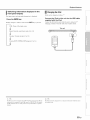
YSP-4300
[ YSP-CU4300 + NS-WSWI60]
YSP-3300
[YSP-CU3300 + NS-WSW160]
Digital Sound Projector TM
Owner,s Manual
English
for North America
J
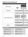
What you can do with this unit
TV
Audio/video device
Preparation
Connections/Basic
Playback
2En
settings
p. 39
3En
Contents
PREPARATION
Controls
and
functions
...............................................
Center unit front panel (front, top) ...........................................
Center unit rear panel (back) ..................................................
Subwoofer rear panel (back) ...................................................
Front panel display ..................................................................
Remote control ........................................................................
Installation
.................................................................
Recommended installation ....................................................
Conditions that make it difficult for sound beams
to achieve surround sound ....................................................
5
5
6
7
8
9
11
11
11
Enjoying surround effects regardless of conditions
(My Surround) .......................................................................
12
If the TV remote control does not work properly after the center
unit is installed (TV Remote Repeater function) ................... 12
If the center unit cannot be installed on a TV stand
(increasing the height of the center unit) ...............................
12
Positioning the subwoofer on its side ....................................
13
Installing this unit ..................................................................
14
Preparing
remote control ..............................................
16
Installing the batteries ...........................................................
16
Operation range ....................................................................
16
Connections
..............................................................
17
Connecting
Connecting
satellite/cable
a TV and a Blu-ray disc player ...................
a game console
or
TV tuner .................................................
18
Connecting
Connecting
the FM antenna
(YSP-4300
only) ..............
the wireless
subwoofer
..............................
20
20
19
Initial
settings
............................................................
21
Establishing
a wireless
connection
...............................
21
Group IDs ..............................................................................
21
Displaying
the menu screen on the TV .........................
21
Selecting
the language
for menu display ......................
22
Auto setup for appropriate
surround
effects
(IntelliBeam)
..................................................................
23
Installing the IntelliBeam microphone ...................................
23
Using AUTO SETUP (IntelliBeam) ........................................
24
Saving this unit's settings to system memory ....................... 28
Operating
the unit by TV's remote control
(HDMI
control)
...............................................................
30
PLAYBACK
Playback
features
......................................................
32
Basic operation
for playback .........................................
32
Enjoying sound based on your preference
...................
33
Switching between surround playback, stereo playback, and
target playback modes ..........................................................
33
Playing back digitally compressed formats (MP3, WMA, etc.)
with enriched sound (Compressed Music Enhancer) ........... 33
Adjust volume for each channel ............................................
33
Enjoying realistic surround sounds (CINEMA DSP) ............. 34
Changing the audio output method for surround playback ... 36
Setting the surround decoder ................................................
38
Delivering sound to a specified location
(Target playback mode) ........................................................
39
Using useful features ....................................................
40
Automatic volume level adjustment (UniVolume) ................. 40
Saving energy with the Eco function .....................................
41
Switching information displayed in the front panel display.... 41
Settings each input source (Option menu) ............................
42
FM tuning (YSP-4300
only) ...........................................
44
Tuning into the desired FM station (Frequency tuning) ........ 44
n_l'n
ooil
nan
.1Cat
ont_
nan
4En
:01_
fO
tlD
_mp_
_the
),
y
n
_P
Receiving weak signal ...........................................................
45
Registering FM stations and tuning in (Preset tuning) ........... 45
Playing music stored on an iPod or computer
over a wireless
connection
...........................................
48
Playing music stored on an iPod or USB device
over a USB connection
(YSP-4300
only) .....................
48
Connecting an iPod ...............................................................
48
Operating an iPod via the TV screen .....................................
49
Using the iPod to control operation .......................................
52
Charging the iPod ..................................................................
53
Connecting a USB device ......................................................
54
Operating a USB device via the TV screen ........................... 55
SETTINGS
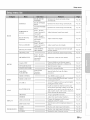
Setup
menu ...............................................................
Setting the setup menu ................................................
Setup menu list ............................................................
BEAM settings ..............................................................
HORIZONTAL ANGLE ..........................................................
BEAM TRAVEL LENGTH ......................................................
FOCAL LENGTH ...................................................................
IMAGE LOCATION ................................................................
CHANNEL OUT .....................................................................
SOUND
settings ...........................................................
SPEAKER LEVEL .................................................................
Adaptive DRC ........................................................................
DYNAMIC RANGE ................................................................
62
62
62
63
Dolby PLIIx PARAMETER .....................................................
HDMI setup ..................................................................
HDMI CONTROL ...................................................................
HDMI AUDIO OUT .................................................................
TV INPUT ..............................................................................
63
63
63
63
63
yAired settings ..............................................................
iPod INTERLOCK ..................................................................
GROUP ID .............................................................................
64
64
64
DISPLAY
settings .........................................................
DIMMER ................................................................................
OSD LANGUAGE ..................................................................
DISTANCE UNIT ...................................................................
65
65
65
65
INFORMATION
settings ...............................................
AUDIO ...................................................................................
VIDEO ...................................................................................
SYSTEM ................................................................................
65
65
65
65
Advanced
setup
........................................................
66
TROUBLESHOOTING
Troubleshooting
.......................................................
General ..................................................................................
FM tuner (YSP-4300 only) .....................................................
USB device (YSP-4300 only) ................................................
Remote control ......................................................................
Messages
..................................................................
iPod (when connected via USB jack)/
USB device (YSP-4300 only) ................................................
68
68
70
70
70
71
71
APPENDIX
Glossary
....................................................................
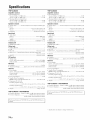
Specifications
...........................................................
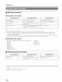
Available
signal information
.........................................
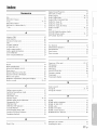
Index ..........................................................................
tli
m_t
58
58
59
60
60
60
60
61
61
[l
ons _or _
72
74
76
77
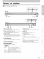
Controlsand functions
Centerunit front panel(front, top)
I
iNPUT
--
YSP-CU4300
VOLUME
+
V
I
NPUT
- VOLUME
+_
YSP-CU3300
ilii_i_i_ii
_
1
V
', ,,iiiiii_'_!_i_i
II!............
Remote control sensor
Receives
infrared
Remote
signals
control
Receives
infrared
the TV Remote
sensor
signals
Repeater
@ STATUS indicator
from
the remote
control
(_'p.
9).
of a TV
fi'c)m the TV remote
function
is enabled
control
when
(_ p. 12).
O Wireless module
Receives
signals.
in front of the wireless
with the w'ireless
wireless
up when
standby
mode.
INPUT
the power
is turned
on, and goes off in the
)
key
Selects
the playback
component
(_ p. 32).
VOLUME (+/-) key
and sends w'ireless
objects
Lights
module's
Do not place
module
ability
as they
to receive
metal
may interfere
and send
signals.
Adjusts
the volume
of the unit (_ p. 32).
@ _ key
Turns
on the unit or set it to the standby
mode.
Front panel display
Show's
information
about
the operational
status
of this unit
n the standby
(_ p. 8).
ower
USB jack (YSP-4300 only)
Enables
connection
of a USB
device
(_ p. 48, 54).
infi:ared
in order
signals
mode,
this unit consumes
to search
for HDM[
fi:om the remote
a small amount
signals
of
or to receive
control.
SURROUND indicator
Lights
up according
to the input
Displayed
color
signal.
Input
signal
Blue
Following surrotmd audio signal lormats:
Dolby TrueHD, Dolby Digital Plus, DTS-HD
Master Audio, DTS-HD High Resolution,
Multi-channel Linear PCM
Orange
Surround audio signal other than above
Off
Stereo/monam'al
audio signal or no signal
SEn
Controls and functions
Center unit rear panel (back)
@
FM ANTENNA jack (YSP-4300 only)
Connect
all FM antenna
(_ p. 20).
satellite
INTELLIBEAM MIC jack
Connect
the supplied
[ntelliBeam
microphone
(_p.
24).
Q
analog
cable
to the external
components
O
(_*_p. 19).
components
a coaxial
digital
audio
cable
to the external
(_*_p. 19).
expansion
jacks
(_*:p. 18).
SEn
an HDM[
disc player,
console
(_p.
18, 19).
expansion
terminal
for commercial
use only.
INPUT DIGITAL TV/OPTICAL jacks
an optical
cable
to the external
components
@
TV
Remote
Repeater
Receives
signals from a TV remote control via the front of
the center unit and transmits those signals to the TV when the
center unit obstructs
the remote control sensor on the TV
for commercial
use only.
HDMI OUT (ARC)jack
For connecting
Blu-ray
(_Xp. 18, 19).
IR IN/OUT jacks
Control
compatible
TV tuner and game
RS-232C terminal
For connecting
AUX INPUT DIGITAL jack
For connecting
HDM[
and cable
A control
O INPUT ANALOG L/R jacks
For connecting
HDMI IN jacks
For connecting
compatible
(_*:p. 12).
Power cable
TV and monitor
For connecting
to an AC wall outlet
(_p.
18).
Controls and functions
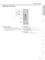
Subw00ler rear panel (back)
ilii
_i_i_ii
_
', ,,iiiiii_'_!_i_i
II!............
Group ID switches
When the center unit and subwoofer are connected
LINK indicator
wirelessly, sound is output from the subwoofer (yAired). For
a wireless connection, use the same group ID as the center
unit and YIT-WI2TX (r'p. 20).
Heat discharge unit
Shows
wireless
Discharges
cover
O
connection
heat
the heat
generated
discharge
status
inside
(_p.
21).
the subwoofer.
Do not
unit.
Power cable
For connecting
)
to an AC wall outlet
(_Xp. 20).
_ :7
7En
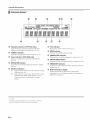
Controls and functions
Frontpanel display _)
mmmJl
li_ml
mmmml
mmm_m
mmlJJ
_l|mm
gm|ml
Playback
indicators
(YSP-4300
only)
Lights while music stored on an iPod or USB device
connected to the USB jack is playing (_ p. 48, 54).
TARGET
(YSP-4300
RX
indicator
indicators
Lights while the connection to the subwoofer is being
established (_,:p. 20).
Lights while the connection to YIT-WI2TX is being
established. For details of YIT-WI2TX, refer to
"Safety and Accessory [nformation" (separate
booklet).
Note that the front panel display turns off when the Eco fnnctinn is
enabled and remains off unless an operation is perfnrmed.
SEn
_mWU
|JJJ_
_umll
_Jm_m
lJ_ml
ilgll
M_WMm
ll|ll
iU|_m
mmm_u
miami
llmll
HDMI indicator
CINEMA
only)
Lights when the TV Remote Repeater function is enabled
(_ p. 10).
TX
gff_ng
Lights tip when HDM[ signals are input.
DSP indicator
Lights tip when a sound field program is selected (_ p. 34).
Lights up when this unit is tuned into an FM station
(_:'p. 44).
Wireless
UB|_
Indicates the current volume level (_ p. 32).
@
Lights when target playback mode enabled (_,:p. 39).
REPEATER
BJg_B
VOL indicator
indicator
Tuner indicators
gHgHB
UNIVOLUME
indicator
Lights tip when the UniVolume function is enabled (_: p. 40).
@
ENHANCER
indicator
Lights tip when the Compressed Music Enhancer function is
enabled (_: p. 33).
O
Multi information
display
Display playback device input source and surround
information (_,:p. 41). Displays settings and information as
alphanumeric characters.
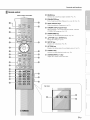
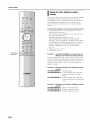
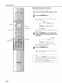
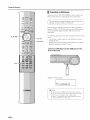
Controls and functions
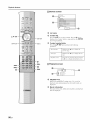
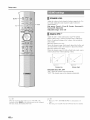
Remotecontrol
@
Infrared signal transmitter
BEAM key
Switches
tile sound
beam
output
lllethod
(ir_ p. 37).
@
ENHANCER
key
Turns Compressed Music Enhancer to on or off (_p. 33).
@
Input selector keys
Select the playback component (_ p. 32).
@
CINEMA
DSP program
keys
When playback is ill surround playback mode, select the
CINEMA DSP programs (_,: p. 34).
@
SURROUND
key
Switches to surround playback mode (_,:p. 34).
@
A/V/_/I_
keys, ENTER
key
Change the setting (_ p. 58).
@
SETUP key
Displays the setup menu (_p. 58).
@
OPTION key
Displays
@
menu
for each
input source
(_ p. 42).
', ,,iii;ii_'_!_i_i
II!............
TARGET key
Switches
@
the option
ilii_i_i_ii
_
to target
playback
mode
(_,: p. 39).
SUBWOOFER (+/-) key
Adjusts
the volume
of the subwoofer.
)
|
YSP-3300
_:_i_iii!i_
!!iiii';
\
/
YEn
..
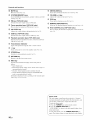
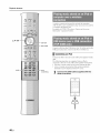
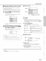
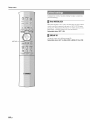
Controls and functions
@ MUTE key
Mute
the sound
@ SYSTEM MEMORY keys
Saves
[ntelliBeam
settings
@
UNIVOLUME
key
Turns the UuiVolume function on or off (_ p. 40).
@
VOLUME
(_: p. 32).
measurements,
speaker
volume,
(_: p. 28).
@
@ FM key (YSP-4300 only)
Switches
this tmit's
input source
to FM radio.
@
@ Tuner operation keys (YSP-4300 only)
Press
to select or register
all FM station
the volume
balance
during
(_ p. 44).
playback
ECO key
Turns the Eco function on or off (_ p. 41).
REMOTE
REPEATER
key
Turns the TV Remote Repeater function on or off (_ p. 12).
@
@ CH LEVEL key
Adjusts
(+/-) key
Adjusts the volume of the unit (_ p. 32).
and other
(_ p. 33).
iPod CONTROL key (YSP-4300 only)
Press to display the iPod browse/playback screen on the TV
(_ p. 51 ).
@ USB key (YSP-4300 only)
Switches
@
this unit's
Perform
USB
input source
to USB
(_ p. 48).
operation keys (YSP-4300
Playback
playback
device
operations
for music
only)
stored
on an iPod or
(_: p. 48).
@ Transmission indicator
Lights
with
operation
using this unit's
remote
control.
@ (.5key
Turns
on the unit or set it to the standby
mode
(_ p. 32).
@ STEREO key
Switches
to stereo playback
mode
(_ p. 33).
@ RETURN key
Returns
to the previous
menu screen.
@ INFO key
Switches
follows.
the information
•
[nput:
[nput
•
Beam:
Beam
surround
•
Decoder:
•
Cinema
(only
mode
Sound
panel
as
setting
displayed
(stereo,
beam
stereo,
target,
or
mode)
signal decoder
Sound
in surround
[nformatiou
source
on the front
name
playback
DSP:
display
field
playback
varies
currently
program
selected
of CINEMA
DSP
mode)
according
to the selected
input
(_: p. 41, 51, 53, 56).
Demo
mode
This uuit outputs
moving
souud
horizontally
beam
dowu-mixed
can feel how' sound beam
To activate Demo mode:
is output
from
"1 Press
the TARGET
key on the remote
2 Press
the CINEMA
DSP OFF
"AUTO DEMO" is shown
demo mode starts.
To exit demo
again.
mode,
The display
to 1 chauuel
to right and left. By this function,
control.
key.
in the front panel
press the CINEMA
returns
to target
you
this unit.
DSP
playback
display
OFF
mode
when
key
display.
J
lO En
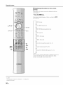
Installation
To achieve
waves,
desired
referred
connect
external
surround
sound
to as "sound
devices
effects,
beam(s)"
such
install
this unit where
ill this manual
there
are no objects
(_,: p, 14), Depending
as a TV first, See "Connections"
such as furniture
on the location
where
obstructing
the path of sound
the unit is installed,
it may be easier
to
(_,: p, 17),
f
Notes
• This unit requires sufficient sp_ce li)r heat discharge.
A mininmm of 5 cm (2 in) above and behind and 1 cm (13/32 in) to the sides of the center unit
A minimum of 21) cm (7-7/8 in) above, behind, and to the sides of the subwoofer
Do not cover the subwoofer heat discharge unit on the back of the subwooli2r.
• Be sure to install this unit where it does not fall subject to vibrations, such as from an earthquake, and where it is out of the reach of children.
• When using a cathode-ray tube (CRT) TV, do not install this unit directly above your TV.
• If the picture on your TV screen becomes blurred or distorted, we recommend moving this unit away li'om your TV.
Center unit
--
Subwoofer
ilii_i_i_ii
_
', ,,;ii;ii_'_!_i_i
II!............
Some
TVs have sensors
the seusors
or sigual
such as the motion
trausmitter
seusor
or signal
from fuuctiouiug,
transmitter
Set the ceuter
for 3D glasses
uuit away
in frout. Iustalliug
from your
the ceuter
uuit may iuterrupt
TV.
)
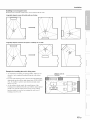
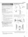
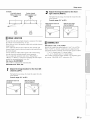
Recommendedinstallation
Center
unit
Subwoofer
• [nstall the center unit in the center of the left and right walls,
• Place the center unit on a TV stand in front of the TV,
• To prevent
slightly
Use the TV Remote
Repeater
obstructs
control
the remote
[ncrease
the height
for center
function
sensor
of the center
unit installation
• The listening position
the front of the center
unit can be mounted
BRACKET
SPM-K20
Manual and SPM-K20
• When
strong
is too high
12),
enough
sufficient
position
be located
and the center
at
unit
off of walls,
angle
the subwoofer
of the room.
the subwoofer
to support
on a rack,
the subwoofer
be sure the rack is
and that it leaves
space for heat discharge,
unit and subwoofer
Subwoofer
performance
i©
communicate
may be affected
placed on a metal rack, or if there
subwoofer
and the center unit,
• The subwoofer
on a wall using WALL
reflecting
the center
installing
• The center
as sofa, etc,) should
• The distance between the listening
should be more than 1,8 m (6 ft),
• This
unit
unit if the TV stand
(_,:p,
(such
unit,
if the center
on the TV (_,: p, 12),
sound
toward
can also be placed
wirelessly.
if the subwoofer
is a metal plate
between
is
the
i
on its side (_,: p, 13),
MOUNT
(option),
Refer to the SPM-K20
[nformation
for YSP-CU4300/
[nstall
YSP-CU3300.
Conditionsthat make it difficultfor soundbeamsto achievesurroundsound
This unit creates
surround
sound
by reflecting
produced
by this unit may not be sufficient
• Rooms
with walls
• Rooms
with acoustically
inadequate
for reflecting
absorbent
projected
when
sound
beams
this unit is installed
sound
• Rooms
beams
walls
of your
where
listening
room.
The surround
sound
effects
locations,
objects
the path of sound
• Rooms with measurements
outside the following
range:
W (3 to 7 m (10 to 23 ft)) x H (2 to 3,5 m (7 to 11,5 ft)) x
D (3 to7
off the walls
in the following
such
as furniture
are likely
to obstruct
beams
• Rooms
where
the listening
position
is close to the walls
• Rooms
where
the listening
position
is not in front
of this unit
m (10 to 23 ft))
• Rooms with less than
this unit
1,8 m (6 ft) from the listening
position
iiili_i_ii:i
to
11 En
Installation
Enj0ying surround effects regardless of conditions (My Surround)
The My Surround
"Changing
function
the audio
creates
output
rich surround
method
sound
for surround
effects
playback"
ill rooms
with less than optimal
surround
sound
conditions
(,_p.
11 ). See
(,_ "p. 36, 37) for more information.
If the TV remotecontroldoesnotwork properly after the centerunit is installed(TV Remote
Repeaterfunction)
The TV may not respond
to commands
from
its reruote control if the center unit obstructs
the remote
control
this occur,
press
sensor
on the TV. Should
the RI_MOTI _
RI_pI_ATI_R
key on this unit's remote
control more than 3 seconds to set the TV
Remote
Repeater
REPEATER
function
indicator
display will light.
When the TV remote
center
unit's
Remote
remote
Repeater
transmits signals
to the TV.
Signals
@
from
to enable.
TV remote
TV remote
control sensor
control
The
on the front panel
control
control
is aimed
sensor,
at the
the TV
TV Remote Repeater
on the back of this unit
from the TV remote
the TV remote
control
control
can be transmitted
to the TV while this unit is in standby
mode.
Note
This function
can be used
while
the TV remote
control
is using infrared
signals.
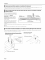
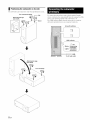
If the centerunit cannotbe installed on a TV stand(increasingthe heightof the centerunit)
In most cases,
necessary.
the center
Attach
unit can be placed
on a TV stand. The supplied
both the left and right spacers
Align the protrusions on the back of the spacer with the
mounting holes on the bottom of the center unit and press
the spacer firmly into place.
Spacer
can be attached
to increase
Removing the spacers
Pull the spacers
straight
up.
Pull the spacer straight up.
Protrusions
Mounting
Bottom of the center unit
12 En
spacers
to the unit.
holes
the height
of the unit if
Installation
Positioning the subwoofer on its side
The subwoofer
call be laid on its side when
_ositioned
on a rack.
Turn counterclockwise
Removing the legs
and sheets
Sheet
ilii_i_i_ii
_
$
', ,,iiiiii_'_!_i_i
II!............
Attaching the legs
and sheets
i!il Z;i:i_
_!_iZI_II'I!II
I
!i!i _iiiii_iiii_
_
Turn clockwise
$
13 En
Installation
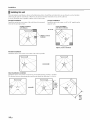
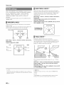
Installing this unit
This unit outputs
obstructing
You may install
Parallel
sound
beam
the path of sound
this unit ill parallel
ill the illustrations
Otherwise,
below'. Install this unit where
the desired
surround
sound
Corner
center
effects
there
are no obstacles
such
of the wall when
it is measured
the left and right corners,
installation
[nstall this unit in the corner
adjacent
at a 40 ° to 50 ° angle
walls.
Corner installation
Parallel installation
(with 5Beam)
(with Stereo+3Beam)
40° to 50 °
Objects, such as
furniture
Objects, such as furniture
Parallel installation
[nstall this unit as close to the exact center of the wall as possible.
Ideal
installation
condition
[nstall this unit as close to the exact front of your normal listening position as possible.
The distance between
listening position and the unit should be more than 1.8 m (6 ft).
More
than
1.8 m
(6 ft)
¥
14 En
as furniture
may not be achieved.
with the wall or ill the corner.
installation
[nstall this unit in the exact
from
as shown
beams.
from the
Installation
Installing in a non-square room
[nstall this unit so that the sound beams call be reflected off the walls.
Irregularly
shaped rooms with solid walls on all sides
Irregularly
shaped rooms that are open to a hallway
ilii_i_i_ii
_
on one side
', ,,iiiiii_'_!_i_i
II!............
c:
Example
for installing
• As sound
obstacles.
sounds.
•
beams
the unit
normally
And a cupboard
In a case of the listening
adjusting
the position
(_: p. 23) enables
effects
installed
facing
room as shown
tables
are not
the wall reflects
--
Objects, such as
furniture
in the right illustration,
of the right channel
to achieve
room
tables,
after AUTO
more desired
surround
SETUP
sound
(_: p. 61).
• As the curtains
listening
in living
pass through
room
absorb
and the case with
function
enables
listening
room
sounds,
is different
the sound
features
of the
from the case with the curtain
the curtain
closed.
Using
to save the best settings
saving
opened
settings
for each case of
(_: p. 28).
15 En
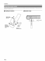
Installation
Before
installing
Information"
batteries
(separate
o1"using
the remote
control,
be sure to read battery
Installingthe batteries
Pull up on the
latch to release
the cover
and remote
control
precautions
ill "Safety
and Accessory
booklet).
Operation range
1
ll
,_i
¸¸
_,ii,ii,i_,_,_J_,_
_"_'_'_ii_iiiiiiiii!!!!!i!!i!!!
iii!iiiiiiiiiiiiiiiiiiiiiiiiiiiiiiii
!i!i!iiiiiiiii!
iiiiiiiiiiiiiiiiii
ft)
3
Insert the
protrusions
into the slots
and close the
cover
G
Battery x 2
(AAA, R03, UM-4)
16 En
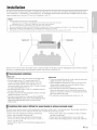
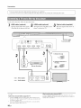
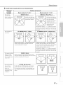
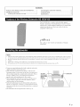
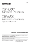
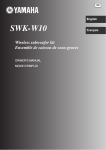
Connections
When external devices such as a TV, Blu-ray disc player, and/or game console are connected, audio
and video signals are transmitted as shown below.
_
_
Audio connection
Video connection
_
f_
_;
_
Audio and video connection
This unit: Plays audio from TV broadcasts,
Blu-ray discs, etc.
HDMI cable
iliiii_iiii_
_
iC,
i
P
Use to connecl a TV that does not
support audio return channel
(AR() to this unit (*_'p. 18).
', ,,iiiiii_'_!_i_i
II!............
HDMI cable
Game console
(HDMI compatible)
__
W
%_ _ __ _ __ _ __
__#
/
i
Optical cable _
f
_
Blu-ray disc player
Comp_ite
video cable
Satellite and cable TV tuner
(not HDMI compatible)
TV: Plays video from TV
broadcasts, Blu-ray disc
player, etc.
_ ;!i;¸
17 En
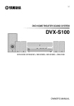
Connections
_]
Do not use
connect
excessive
the power
force cable
when until
inserting
all connections
the cable
For the cable
connection,
follow
the procedure
plug,
are completed,
Doing so may damage
the cable
;he digital
Of the Blu-ray
audi;/video
disc player
;ignMs
to this unit.
J
jack.
below,
HDMI Cable (optional)cable(opti0nal)3
inpu[
plug and/or
optical Cable(supplied)
The digital
player
videO ofihe
is reflected
BiuT;ay
disc
on TV:
back digital
soun]ts
of TV ;n
this unit.
To AC wall outlet
INr b._AM
FV '_N_T?_NA
_,_lC
OUT
(ARO]
INPUT ANA O_
IN_
2
AUX
I_LT ;;ISI [_t
IN2
HOMI
INS
V_IN
InO
INa
1
RZ-2a2C
DD]
TV
INPtr
OmlCAL
01_1 _E
3
i
Blu-ray disc player
_
" Video signals
_
" Audio signals
Audio return channel (ARC) supported TV
• ColmectanHDMlcabletotheaudioremrnchannelsupl_ortedjack
(the jack with "ARC" indicated) on TV. In this case, you do not need
to connect an optical cable.
• Activate the HDMI control function of this trait so as to activate the
audio return channel (ARC) (_,p. 63).
18 En
TV
What is audio return channel (ARC)?
A [iulction transmits digital audio signal output l]'orn TV to this tlnit
through an HDMI cable. By this flmction, an optical cable to connect TV
and this trait is not needed.
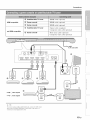
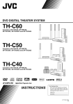
Connections
HDMI compatible
not HDMI compatible
Satellite/cable TV tuner
HDMI cable (optional)
Game console
HDMI cable (optional)
Game console
HDMI cable (optional)
Satellite/cable TV tuner
Optical cable (supplied)
Composite video cable (optional)
Game console
RCA stereo cable (optional)
Composite video cable (optional)
>
ilii
_i_i_ii
_
To AC wall outlet
-,\
', ,,iiiiii_'_!_i_i
II!............
iiili{_ii_i
To connect a device with an AUX output jack, connect its AUX output
jack to the AUX INPUT DIGITAL (coaxial)jack on this unit via a
commercial coaxial digital audio cable.
19 En
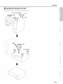
Connections
Connect
the supplied
FM antenna
via the FM ANTENNA
jack.
FM antenna
\
To connect
the subwoofer
wirelessly
center
(yAired),
unit and subwoofer.
components
plugging
When
must
wireless
power
using the transmitter
subwoofer
and center
the center unit enters
indicator
turn off.
unit and subwoofer.
standby
outlet.
1}, the same group
2TX is A 1.
lights when the subwoofer
ID
The default
is on and the
wirelessly.
mode,
Group ID switches
by simply
into an electrical
unit are connected
to the
ID for both
connection
cable
unit
be assigned
group
(Y[T-WI2TX)
to the center
group ID of YIT-WI
The LINK indicator
to the center
ID must
The default
is A 1, enabling
the subwoofer's
be assigned
When
LINK
(NS-WSWI60)
the same group
LINK indicator
the subwoofer
and
O
?,_'- Tip
ee page 21 t:_rmore int:_rmalionon group ID.
)
Blinks:
Lights:
LINK
Establishing
connection
Connection
established
To AC wall outlet
For details of"YIT-WI2TX,
(separale booklet).
20
En
re[er lo "Safety and Accessory
hfformation"
Initial settings
Yamaha's
connection
proprietary
yAired technology
enables the wireless
of the center unit and subwoofer.
Wireless
connection
of the subwoofer
concern
allows
for cables.
iPods
or computers
stored
on these
for subwoofer
When
through
of YIT-WI2TX,
[nformatiou"
(separate
When
playing
center
unit transmits
When
group
2TX)
is used,
YIT-WI2TX
the
stored
signals
for switching
_
on an
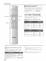
Switch
'snoPuU
tce s
select
this unit.
When
this unit and the TV
are connected
by the
to play songs
sends audio
TV remote control (example)
its
between input sources on the
TV's remote control to
disc player,
that are received
is used
YIT-WI2TX
of this unit
Use the button
and Accessory
fi'om a TV or Blu-ray
signals
operation
is possible by displaying
menu screen on the TV.
to play music
this unit.
refer to "Safety
audio
by the center
The same
(YIT-WI
wirelessly
Visual
without
booklet).
content
iPod or computer,
received
the transmitter
call be connected
devices
For details
subwoofer.
installation
as shown
below', select
"HDM[
1".
that are
unit and subwoofer.
[D must be assigned
default,
the ceuter
unit,
subwoofer,
a group
ID of A 1. This group
to all components.
aud YIT-WI2TX
ID does
By
are assigned
uot ueed to be chauged.
GrouplDs
TV
The center
group
unit, subwoofer,
ID from three
AI-A3,
BI-B3:
C1-C3:
Use when
unit ff_p.
and YIT-Wl2TX
possible
Audio
sets: A I-A3,
delay
playing
can be assigned
B I-B3,
C 1-C3.
is less than that of the C1-C3
music
stored
a
on a computer
set.
via this
48).
IN1
To prevent
wireless
system
or device
assign
a different
connection
installed
group
of another
yAired
Yamaha
sound
IN2
,,,/
ID to this unit and the YIT-WI2TX.
Changing the group ID
Center
unit
Change
the group
ff_p.
ID from
"GROUP
this unit
ID" in the setup
The menu
meuu
64).
The setup
display
meuu
key is pressed.
Subwoofer
Use the group
change
[D switches
the group
on the back of the subwoofer
[D ff_p.
INS
H_MI
near this unit or the YIT-WI2TX,
to
is displayed
When
on the TV screeu
the TV is receiving
menu is superimposed
over video
second
setup
time to cancel
content.
HDM[
when
the SETUP
signals,
the
Press the SETUP
key a
meuu display.
20).
SETUP MENU
YIT-W12TX
Use the group
the group
Accessory
[D switches
ID. For details
[nformatiou"
on the side of YIT-Wl2TX
of YIT-WI2TX,
(separate
to change
refer to "Safety
and
]HDMI
lyAired
]DISPLAY
booklet).
I_FORMATION
It
he setup
Notetnenu (_Tp. 58) can only be displayed on a TV screen. It
1
annol be shown in the lront panel display.
21
En
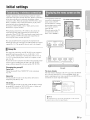
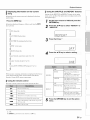
Initial settings
Turn the unit and TV on.
Switch the TV's input to display video
input from this unit (_,p. 21).
J'_ Press and hold the SETUP key until the
"OSD LANGUAGE" menu appears on your
TV._
At'it
OSDLANGUAGE
A
ENTER
B_N
SETUP
DEUTSCH
FRAN_AIS
ESPANOL
ITALIANO
NEDERLAND
PYCCKHN
SVENSKA
Y
Selectable item: E_2k_, ENGLISH, DEUTSCH,
FRAN(_AIS, ESPANOL, ITALIANO, NEDERLANDS,
PYCCKI/II_I, SVENSKA
Initial setting: ENGLISH
When
the
Confirm
screen
the following
is not displayed
cases.
The HDMI input jack of your
of the unit are connected.
The input
22
En
of your TV
TV and the HDMI
is set to "HDMI
OUT
1 (example)".
(ARC)
jack
Initial settings
Assembling the supplied cardboard
microphone stand
Due to differences
in room
unit, and the lifestyle
adjusted
in order
sizes
of users,
and shapes,
settings
positioning
for each
for this unit to provide
channel
the optimal
of this
must be
listening
experience.
This unit is equipped
adjusts
settings
"beam
optimization"
Beam
optimization:
This feature
with
for each
optimizes
the beam
your
listening
Sound
optimization:
optimizes
that the parameters
which
automatically
IntelliBearn
and "sound
matches
This feature
IntelliBearn,
channel.
offers
two features,
optimization".
angle
so that the parameter
Place
best
4
environment.
the beam
best match
delay,
your
volume,
listening
and quality
5
horizontally
so
f
f
f
environment.
This unit performs these two automatic
optimizations
of the supplied
[ntelliBeam
microphone.2)
with the aid
Run through
• The AUTO SETUP procedure nmy not be run successffflly if this
unit is installed in one of the rooms described in "Conditions that
make it difficult lor sotmd beams to achieve surround sound" on
page 11. The My SurromM fimction can be used to enjoy rich
surround sound in these types of rooms as well. See "Changing
the audio output method tk_rsurround playback" 0_p. 36, 37) lor
more information.
Make
sure that there
microphone
obstruct
are no obstacles
and the walls
the path of sound
However,
any objects
regarded
as a protruding
that are in contact
as these
objects
with the walls
will be
part of the walls.
nficrophone
Upper
limit
:h_of
)
Keep the lntelliBeam microphone away from direct sunlight.
Do not place the lntelliBeam microphone on top of this unit.
Within 1 m i3 3 iii!i
:Jj
J
:
t
i' wi
rd
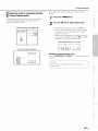
Installingthe IntelliBeam microphone
=
st lnd_
1.8
Place the IntelliBeam microphone
normal listening position.
the [ntelliBeam
room
beams.
llltelliBeam
• Do not connect the lntelliBeam microphone to an extension
cable as doing so may result in an inaccurate sound optimization.
• After you have completed the AUTO SETUP procedure, be sure
to disconnect the lntelliBeam microphone.
• The IntelliBeam microphone is sensitive to beat.
between
in your listening
m (6.0
fl)
__
Lower
limil
at your
f
• Use the supplied
place
cardboard
the [ntelliBeam
ears would
be when
microphone
microphone
stand
or a tripod
at the same height
i;_{:_
¸¸
to
as your
you are seated.
• Position
the [ntelliBeam
the floor.
microphone
so that
it is parallel
with
i
CaMboard
•
Up to three
lhis unil's
• "BEAM+SOUND
OPTIMIZE" screen appears automatically when
the lntelliBeam microphone is connected. "BEAM OPTIMIZE
ONLY" or "SOUND OPTIMIZE ONLY" can be selected separately
in the setup menu(_ p. 26).
on lislening
microphone
sels of aulornatically
memory
room
(_p.
configured
28). You
and you can
stand
can save
change
sellings
the several
lhe setting
can be stored
in
Z
dala depending
conveniently.
23
En
Initial settings
Using AUTO SETUP (IntelliBeam)
f-
• It is normal for loud test tones to be ot/tput dm'ing the AUTO
SETUP procedure. Make sure that there are no children around
in the listening room while the ALTTOSETUP procedure is in
progress.
• If there are curtains in ynur listening room, we recnmmend
lollowing the procedure below.
1 Open the curtains to improve snund reflectinn.
2 Run "BEAM OPTIMIZE ONLY" (_,p. 26).
3 Close the cm'tains.
4 Run "SOUND OPTIMIZE
ONLY" (_p.
26).
• Make sure that your listening room is as quiet as possible. For
accurate measurement, turn oft" air conditioner or other devices
that make noises.
ENTER
_RETURN
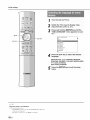
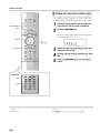
Turn the unit and your TV on.
Switch TV input to display video input
from this unit (_p. 21).
SYSTEM
MEMORY
Connect
the IntelliBeam
microphone
the
INTELLIBEAM
MIC jack on
the rear oftothe
unit.
II
24
En
® 2¢01
_,'
_'_][NNA
I
IMI
'c "'
UNPU
•
ANALOG
Initial settings
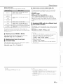
The screen
[ntelliBeam
below' is displayed
after connecting
microphone
to the unit. 1)
AUTO
SETUP
(PREPARATION
Please
connect
Please
place
1.8m/6tt
away
Measurement
& CHECK)
the MIC.
the MIC
from
results
are applied
to this unit.
at [east
Sound
AUTO
Pro-
SETUP
COMPLETE
jector.
The MIC should
be set
at ear level when
seated.
Measurement
After
takes
[ENTER[
please
about
Please
3rain.
[ENTER]:Start
remove
the
MIC
from Sound
Prolector
and the listening
position.
is pressed,
leave the room.
[RETURN]:Cancel
Press
[SYSTEM
to save
set-up
MEMORY1
key
in the memory.
• The measurement results are stored in the internal
in lhe room, you may obslruc/the beam, or the microphone may pick
up
any sOUnLIsyou
make,
possibly
resulling
Follovv'
the inslructions
below
anLIthen
leave in
theimproper
room. If you remain
cnnfiguralion ol sellings.
memory of this unit until you run the AUTO SETUP
procedure again or configure the settings manually.
• You can save the several measurement results pressing
the SYSTEM MEMORY key (_<p. 28).
/
6
Remove the IntelliBeam microphone
i
/. .................
i>
ilii
_i_i_ii
_
The "AUTO SETUP COMPLETE"
The screen
SETUP
automatically
changes
during
screen closes. 5}
Keep the [ntelliBeam microphone in a safe place.
the AUTO
procedure.
', ,,iiiiii_'_!_i_i
II!............
AUTO
Wi[[
SETUP
begin
Please
START
in 10 sec.
leave
the room
[RETURN]:Cancel
m
(After
=
3 min.)
)
SHOW
RESULT
MESUREMENT
ENVIRONMENT
BEAM
MODE:
COMPLETE.
CHECK:
[ENTER]:Save
[RETURNI:Do
If the AUTO
rings
SETUP
the chimes.
Success
5Beam/Plus2
set-up.
not
procedure
save
set-up.
is complete,
this unit
3}
"BEAM+SOUND OPTIMIZE" is selected automatically. When you
perlorm "BEAM OPTIMIZE ONLY" or "SOUND OPTIMIZE ONLY"
only, relier to "AUTO SETUP via setup menu" (_,p. 26).
_ng
•
•
•
Wait outside the room during the AUTO SETUP procedure.
Remaining in the room after the AUTO SETUP process begins may
result in the improper configuration of settings as your body may
obstruct sound beams or the microphone may pick up sounds you
make inadvertently.
The AUTO SETUP procedure takes about 3 minutes.
To cancel the AUTO SETUP procedure after it is started, press the
RETURN key.
II an
error
occtlrs,
all error
bLizzer
sounds
and
an
error
message
is
displayed. For details on error messages, see "If an error message is
displayed" <_p. 27).
• lf"ENV1RONMENT
CHECK:Faihu'e" is displayed, accurale
measuremem may not have been possible. See "ERROR-El" uncler
"Error messages" 0_ p. 27) for the remedy 1o Ihis mosl common error.
Press the RETURN key, and begin measurement again.
• Depencling on lhe environmem ol your lislening room, lhe firont lelt
and righl beam angles ancl leR and righl surround beam angles may be
sel to Ihe same value even it""BEAM MODE :5Beam" is displayed as
a result.
_ng
11you do not warn to apply' the resulls, press RETURN
key,.
When AUTO SETUP is performed from the setup menu. the menu
selection screen ollhe setup menu appears.
25
En
Z
Initial settings
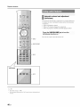
AUTO SETUP via setup menu
1
Place the IntelliBeam microphone at you r
normal
listening position, and press the
SETUP key.
See "Installing
instructions
the [ntelliBeam
on positioning
microphone"
(,_xp. 23) for
the IntelliBeam
microphone.
At'it
Fiiiiiiiiiiiiiiiiiiiiiiiiiiiill
ENTER
SETUP
RETURN
Select
Item:
"BEAM+SOUND
(Beam
OPTIMIZE"
optimization
and sound
optimization)
Select this optimization
feature if you make
first time. This menu takes about 3 minutes.
"BEAM
OPTIMIZE
(Beam
optimization
Use to optimize
for the
ONLY"
only)
the beam
matches your listening
1 minute.
angle
so that the parameter
environment.
"SOUND
OPTIMIZE
ONLY"
(Sound
optimization
only)
Use to optimize
settings
the beam
best
This menu takes about
delay,
volume,
and quality
so that
the paraineters
best match your
menu takes about 2 minutes.
listening
environment.
This
You must optimize
OPTIM[ZE
ONLY".
cases:
the beam
ONLY"
Select
before
this optimization
• If you have opened
listening
• If you
room
(PREPARATION
displayed.
refer to 'Using
or closed
before
have manually
For the details
angle
"BEAM
"SOUND
feature
OPTIM[ZE
in the following
the curtains
in your
using this unit
set the beam
angle.
& CHECK)" screen is
.........
on connecting
AUTO
with
starting
SETUP
[ntelliBeam
......
microphone,
(IntelliBeam)"
(_,:'p. 24).
Follow steps 4,
and 6 under :fUsing
AUTO SETUP (IntelliBeam)' to configure
settings, and then remove the microphone.
The ENTER key,
26
En
performs
lhe same function as lhe • key.
Initial settings
If an error message is displayed
If all error message
messages"
Follow'
below'
is displayed
to determine
the instructions
below'
on the TV screen,
see "Error
the cause and resolve
to begin
the problem.
measurement
again.
[ERROR E-l]
Press the ENTER key to run the AUTO SETUP procedure again.
Or press the • key to continue the measurement.
[ERROR
Press
AUTO
Remedy
The hnelliBeam microphone is
not placed in h'ont ol this unit.
Position
SETUP
procedure
again
after turning
connection
2
3
The "IntelliBeam"
menu is displayed.
Select "BEAM+SOUND
OPTIM[ZE",
ONLY",
or "SOUND
mode,
then run
this unit on.
betweeu
center unit has been established
Press the RETURN
key.
and begin
in fl'ont ol 1his unit
measurement
again.
the subwoofer
Follow'
Cause
Remedy
The lntelliBeam microphone is
not placed in the right distance
from this unit.
Position the hltelliBeam
microphone at a distance of more
than 1.8 m (6.0 1:) from this unit
and begin measurement again.
Cause
Remedy
The lntelliBeam microphone
cannot collect the sound
produced by this unit.
Position the lntelliBeam
microphone properly, check the
connection, and then begin
measurement again.
Cause
Remedy
An internal s}stem error
occurred,
Press the @ key to mrn this unit
to the standby mode, then run
AUTO SETUP procedure again
after turlfing this unit on.
and
OPTIM[ZE
"BEAM
ONLY"
OPTIM[ZE
and press
the •
steps 4, 5, and 6 to measure
again
(_:p.
25).
[ERROR E-2] through [ERROR E-6]
1 Press the RETURN key.
3
lhe I ntelliBeam
(_: p. 20).
key. I)
2
microl?hone
E-7]
the (}) key to turu this uuit to the standby
[ERROR
E-9]
1 Be sure that a wireless
4
Cause
The "IutelliBeam" menu is displayed.
Select "BEAM+SOUND OPTIMIZE", "BEAM OPTIMIZE
ONLY", or "SOUND OPTIMIZE ONLY" and press the •
key. I)
Follow' steps 4, 5, and 6 to measure again (_:p. 25).
Error messages
Cause
Remedy
There is too much noise in _our
listening room.
Make sure that 2tour listening
room is as quiet as possible. You
may want to choose certain hours
during the day when there is not
much noise coming from outside.
(3
Cause
Remedy
The s[]hx_roo]_r is not connected
wirelessly,
Be sure that at vvrireless
colmection between the
subwooli_r and center unit has
been established 0_ p. 20) and
measure again.
f
)
ii _i_i;iiiiiiii
Cause
The lntelliBeam
disconnected,
Remedy
microphone
is
Connect the lntelliBeam
microphone to the
1NTELL1BEAM MlCjack
rear of this unit and begin
measurement again.
_ :7
on the
Cause
Remedy
Some other operations were
performed on this unit.
Begin measurement again. Do
not perform any other operations
with this unit during
measurement.
Z
27
En
Initial settings
Savingthisunit'ssettingstosystem
memo_
Three
sets of settings
quick
loading
environmental
changes
save [ntelliBeam
surround
can be saved to this unit's
of settings
optimized
as needed.
measurement
setting
memory,
for specific
enabling
listeners
or
Refer to the examples
results
and settings
to system
memory,
settings
can be saved
below' to
such as
or to load a pre-defined
settings.
The following
•
Surround
playback
(_ p. 33), stereo
target playback
rnode (_,_p. 33)
(The sound beam output method
for surround
playback
memory.
(_ p. 33), or
(_,_p. 36) can also be saved
rnode.)
• [ntelliBeam
measurernent
(When "HOR[ZONTAL
LENGTH",
to system
playback
"FOCAL
results (_p. 23)
ANGLE",
"BEAM
LENGTH",
TRAVEL
and "IMAGE
LOCATION"
are configured
in the setup rnenu (_,_p. 58), these settings
applied to IntelliBearn's
AUTO SETUP measurements.)
•
Surround:
CINEMA
(_ p. 38)
• Channel level
• Tone
SYSTEM
MEMORY
control
Example
1
(_:p.
DSP (_,_p. 34), surround
beams,
33, 62)
Saving
the IntelliBeam
that absorb
open
settings
to system
settings
as needed.
sound,
such
of those
and again
memory
Saving
with
frequently
SYSTEM
3:
obstruct
decreases.
closed.
for
memory
sound
Measure
Save
with
both sets of
1 and 2, and load the appropriate
memory
MEMORY
1: Surround
MEMORY
as curtains,
them
2
SYSTEM MEMORY2:
to system
beams
Example
SYSTEM
measurements
environments
the effectiveness
the curtains
decoder
(_,:p. 43)
different
[f materials
are
used
settings
to system
setting
A target
playback
projects
kitchen
sound
mode
beams
A target
playback
projects
sound beams
setting
toward
mode
setting
toward
that
the
that
the living
room
Example 3 Saving preferred listener settings to system
memory
SYSTEM MEMORY 1: Settings configured for Dad
SYSTEM MEMORY 2: Settings configured for Morn
SYSTEM MEMORY 3: Settings configured for parties
28
En
Initial settings
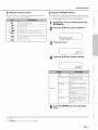
Saving settings to system memory
Loading settings
7
Hold down the SYSTEM, MEMORY 1,:2,
or 3 key until M1Save? ;'M2Save?
;O r
,M3 Save?", corresponding to the button
pressed,
is displayed,
I') Press the same SYSTEM
again])
MEMORY
key
the SYSTEM
1 key is pressed,
"M 1
When
Saving"
is displayed,
MEMORY
and settings
1
Press theSYSTEM
key corresponding
loaded.
If the SYSTEM
Load'?"
9
i..
are saved.
MEMORY
MEMORY
112' or3
to settings to be
1 key is pressed,
Press the same SYSTEM
again.
When
"MI
will be displayed.
the SYSTEM
Loading"
is displayed,
MEMORY
and settings
MEMORY
key
1 key is pressed,
"MI
are loaded.
ilii
_i_i_ii
_
', ,,iii;ii_'_!_i_i
II!............
• If system settings are already stored in the selected memory number,
this unit overwrites the old settings.
• The memory ftmction cannot be set when "MEMORY
set to "ON" in the advanced setup melm (_,p. 66).
PROTECT"
is
29
En
Initial settings
What is the HDMI control function?
HDMI1
This trait call be operated
supports
the HDM[
using a TV's
control
ftmction
reruote
control
if the TV
and is connected
via HDM[ cable (e.g. REGZA
Link; some
The following
6 ftmctions
are supported)}
to this unit
TVs excluded).
Remote control of TV (Example)
1.
Turn on/off
Both
the
TV
and
this/mit
turn
on/off
at
tile same time.
2. Switch
input
sources
• The input source lklr this unit switches
accordingly
when the TV's input
source is switched. The input source
lkw this unit also switches when a
Blu-ray disc player is selected as the
input source from the TV's menu
display.
• The input source
can be switched
while this unit is in standby
3. Control
mode.
volume
This unit's volume can bc ad.justcd when
"HDMI AUDIO OUT" 0" P. 63) is set to
"AMP" (default).
4. Switch the audio output
device (TV or this unit)
5. HDMI signal pass-through
HDMI
input signals
are output
audio content from an HDMI
unit is in standby mode.
6.
ARC
operating
are not able
settings
above
on tilt' TV can bc input to
with
your TV's
these operations,
your TV's
these operations,
remote
configure
remote
you may
control.
HDM[
If you
control
(_: p. 31 ).
• Turning
the UuiVolume
• Operating
En
this unit with
to perform
TVs, the following
device
(AR()jack
described
With some
controlled.
• Navigating
30
from the HDMI
If you are able to perform
continue
• Even if your TV supports the HDMI control Rmction, some functions
may not be available. For details, refer to the manual supplied with
your TV.
• If you connect this unit to a device such as a Blu-ray disc player that
supports HDMI control via HDMI cable, you can control that device
using the HDMI control flmction. For details, relier to the manual
supplied with each device.
• We suggest using devices (TV, Bh>ray disc player, etc.) fi'om the
same manufacturer.
output
try the operations
control.
Video and
from tile TV when this
function
Audio signals
this unit.
First,
from the HDMI OUT (ARC)jack.
input source art.' output
this unit's
function
setup
the browse/playback
connected
additional
functions
can be
on and off
menu displayed
screens
to the USB jack
on the TV
for an iPod or USB
(YSP-4300
only)
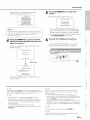
Initial settings
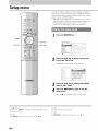
Setting the HDMI control function
If the HDMI control function
Be sure that all components
unit, and that settings
below'.
2
The TV is connected
unit.
Enable the HDMI control function of all
components connected to this unit via
HDMI cable.
"HDM[
CONTROL"
CONTROL"
For external components,
with each component.
3)
refer
to "ON"
to the manual
are properly
connected
configured
to the HDM[
to this
as described
OUT (ARC)
(_,: p. 63) ix set to "ON"
jack of this
in the setup
menl.1.
The HDM[
For this unit, set "HDM[
is not working
are correctly
(_xp. 63)9
check
supplied
or speaker
control
the relative
Nnction
settings
is enabled
on the TV. (Also
such as power
interlock
Nnction
priority.)
When the HDM[ control Nnction
after the above has been checked,
ix not still working
Turn off this unit and the TV, and then turn them
even
back on
again.
Disconnect
external
Registering HDMI compatible
components to the TV 4)
the AC power
components
When the connected
If the Blu-ray
press
disc player
the HDMI1
is connected
of the unit and
cable.
via HDM[
the input
source
connected
{Y)
for the TV and
via HDM[
cable.
Changing the connection method and
connected components
Turn
on an
external
a Blu-ray
disc
player,components,
connected tosuch
this as
unit via HDMI cable.
Select the input source of this unit to
Blu-ray disc player and check whether the
image in the player is correctly displayed
or not.
switch
this unit to the components
Select this unit as the input source of the
TV.
jack,
cable
to the unit via HDM[
Plug them in again after about 30 seconds.
After OPTICAL,
ANALOG,
AUX, YIT, or USB 5) input
has been enabled,
7
I
supply
connected
unit with the following
1
components
and jacks
a:e changed,
reset this
procedure.
ii
Disable the HDMI control function of the
TV and Blu,ray disc player, turn off all
_ii
4
IN I
key.
Zi
Check if the HDMI control function works
(turn on this unit o r adjust the volume level
using the remote control of the TV),
2) :(_s
• The del_.mlt setting is "OFF".
• When "HDMI CONTROL"
4) _(_
is set to "ON"
When the Eco functinn (_,_p. 41 ) is emd_led, this unit enters smndb>
mode if the TV is selected lot audio output using the TV's remote
control.
s> 4<
<i:!
iii iiii!il}_iiii!i
ili {;il)
Input source name
i"i
i;!i¸¸
ii! _ i;_
!
For some HDMI compatible components, registering HDMI compatible
components to TV is not required in this case when the HDMI control
function is enabled.
5) _
YSP-4300 only
The example of TV settings
• From the setup menu on your TV, select "Link setting" _ "HDM]
control setting", then set a setting such as "HDMI control fimction" to
"ON".
• Setting such as "Speaker priority" should be set to "AV amplifier".
31
En
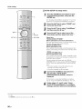
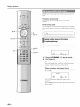
Playbackfeatures
ENHANCER
unit.
d_
HDMI1
Turn
components
disc to
player,ongame
console, (TV,
etc.)Blu-ray
connected
this unit.
In_
keys
SURROUND
Select
by pressing
selectora component
key corresponding
to thethe input
connection of external components.
STEREO
Press
the HDMI1
Blu-ray
key to play audio/video
disc player
connected
content
via the HDM[
from
a
INI jack.
Input source name
)
H[:,l"ii; .t
UNIVOLUME
SUBWOOFER
(+/-)
MUTE
VOLUME
(+/-)
I
Press the SUBWOOFER (+/.) key to
adjust the volume of the subwoofer])
CH LEVEL
•
When
audio
unit, mute
•
When
is output
sound
the VOLUME
input to HDM[
panel
YSP=3300
MUTE
6
CH LEVEL
volume.
• Lowering the subwoofer
32
En
vohlme is recommended
at night.
key.
press the MUTE key. While the mute
blinks.
key again
fl'om the
even if you press
the VOL
To resume
indicator
ill the front
the volume,
o]"press the VOLUME
press the
(+/-) key.
Sra_ebt:k°
mrStUrr:°e_n
dP'baYbkCkod:re°
P y
, i i g P y
,
d
configure sound setting according to you r
preferences (_p; 33).
ress the
ode.
• Tile stlbwoo_'or vohlme Call be adiusted separalely lroln the whole
is output
(+1-) key or the MUTE
is activated,
display
IN jack
level does not change
To mute the sound,
function
and this
the TV sound.
TV, the volume
•
fl'om both TV speaker
.............
(_
key to turn
this
unit
to the
standby
/
/
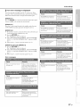
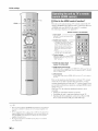
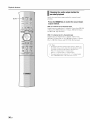
Playback features
Playing back digitally compressed formats
(MP3, WMA, etc.) with enriched sound
(Compressed Music Enhancer)
This unit supports
the following
capabilities
to enjoy
sound
based
on your preference.
• Switching
target
between
playback
• Compressed
surround
stereo
playback,
and
i! '{3¸¸¸
)nodes
Music
iiii il;i;iiiii_;il
Enhancer
• Volume adjustment
• CINEMA
DSP
• Switching
• Surround
playback,
_i'8
ii >
Play back digitally compressed
format such as MP3 and WMA,
with emphasis on bass and treble for extended
dynamic sounds.
for each
channel
Press the key agaiu
between
surround
sound decoder
audio
output
to turu the fuuctiou
off.
methods
Adjustvolumefor each channel
Switchingbetweensurroundplayback,
stereoplayback, and target playbackmodes
Volume
balance
for each chauuel
audio output, s}
cau be adjusted
during
playback
to
Stereo playback mode
FL: Front
playback mode.
left
Press the STEREO key to switch between standard stereo and
FR: Front right
C: Center
beam
SL: Surround
stereo
playback
modes.
Stereo (standard)
Beam stereo
................
I
I
J
! i,.;i
i
left
SR: Surround
right
SW: Subwoofer
....; i i,..i'..i,..;,.;
When "STEREO" is selected, the front channels are the primary
channel sources for output of stereo sound.
When "BM STEREO" is selected, left and right channel sounds
are output as sound beams from the front left and right channels.
C: Center
SL/SR: Surrouud
left and right
Wheu Subwoofer
My Surround
(MY SUR.)
SW:
is selected
(_Xp. 37):"_
This expands the area to which sound is output.
Surround playback
mode
Adjustable
Press the SURROUND
key to switch
surround
playback
mode.
Surround
souud
instructions
methods.
is output
on switching
as sound
beams.
betweeu
the souud
See page
beam
range: -20 to +20
t°
# .................
36 for
output
_;j 133
_ii!G'_!
_
iiiI ({i}iiii
Target playback mode
!i!iii_!_i_}!_i
iiii {iiiii)
iiii ,_'"{'i
playback mode.
Target
playback
mode focuses
souuds
from all channels
beams from a single channel to achieve optimal listening
specified
listener. See page 39 for more information.
as sound
for a
# ...................
4) _(_>_
• By delault, this fimctiou is set to "ON" when the input source is Y1T
or USB (YSP-4300 only). It is set to "OFF" with any other input
source.
• Compressed Music Enhancer does not work in case nllhe following
digital audio signals:
- Dolby TrueHD, DTS-HD Master Audio, etc.
- Signal that sampling rate is more than 48 kHz.
_ng
Example of volume balance
• It" _ou have problems hearing words: Select C (center) to increase the
level.
iili!i!iiii!!iii
When the sound is not like surround sound: Select SL (surrnnnd left)
and SR (surround right) to increase the level.
• The volume of the subwooli_r also can be adjusted by using the
SUBWOOFER (+/-) key.
ii:i;il}iii_i_
;>:_ii
s) _:_
Relier to "SPEAKER LEVEL" (_p.
each channel with the test sound.
62) when adjusting the volume of
33
En
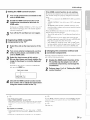
Playback features
Enjoying realistic surround sounds (CINEMA
DSP)
Playback
DSP.
surround
sounds
using
Yamaha's
exclusive
CINEMA
1)
Press the SURROUND
the surround mode.
2
DSP
key to switch to
Press the CINEMA DSP (MOVIE, MUSIC,
or ENTERTAINMENT)
key repeatedly to
select the desired program.83_
SURROUND
The
CINEMA
This
DSP
unit is equipped
processing)
enhance
chip
concert
containing
your playback
are precise
digital
balls,
with
music
a Ymnaha
several
experience.
recreations
relines,
CINEMA
sound
Most
of actual
and movie
DSP
(digital
sound
field
field programs
used
to
of the CINEMA
DSP
programs
acoustic
theaters.
envirolm/ents
of fi_mnus
CINEMA
panel
display
lights
up.
The CINEMA
conditions.
•
Audio
DSP
and
category
the
DSP programs
signals
being
played
•
When
using
•
When
playing
•
When
target
name
CINEMA
are not available
witll sampling
fi'equellcy
appears
DSP
ill the
indicator
front
(_,: p. 8)
in the following
of higher
than
48 kHz are
back.
My Surroundfimction6_
back
in stereo
playback
mode
p. 37).
playback
mode.
is enabled
6_p.
39).
s) _:_
This
unit
source.
automaticall_
When
last settings
34
En
you select
memnrizes
annther
for the selected
input.
tlle settings
input,
the unit
assigned
tn each
automatically
inptlt
recalls
tlle
Playback features
CINEMA DSP options
Sports
Sci-Fi
This program
clearly
effects
of the latest
broad
and expansive
reproduces
science
dialogs
fiction
cinematic
films
and special
This program
sound
and lets you feel a
center
space,
reproduces
sports broadcasting,
the energetic
converging
and broadening
the overall
atmosphere
and lets you feel as if you are seated
Adventure
reproduces
latest action
excitement
the thrilling
environment
films and lets you feel the dynamic
of fast-moving
stadimn
or a
il;i;iiiii_;il
and
This program
reproduces
excitement
of live talk
enhances
the ambience
of gaiety while
conversations
at a comfortable
volume.
reproduces
lets you have
added impressions
strong
impacts.
visual
the wide
and grand
environment
on spectacular
scenes
effects
around
Concert
creates
a rich surround
hall with a great
of sounds,
close
to the center
Jazz
Club
This program
Line",
effect
deal of presence,
and lets you feel
of a large
round
emphasizing
the
as if you are seated
of the stage.
recreates
a famous
environment
of "The
jazz club in New York
reverberations
from
and offers
serious
that match
dramas
an optimum
tones and background
clear words.
3D feeling,
music
a wide range
to musicals
softly
and
reproducing
but cubically
Game
This program
games.
is suitable
It utilizes
scenes
for role-playing
the sound
field effects
and adventure
for movies
to
play,
in the game.
right in front of the stage.
Set CINEMA
produces
It
once and lets
Video
This program
stables
genres
represent
the depth and spatial feeling of the field during
while offering movie-like
surround effects in the movie
the acoustic
you feel as if you are seated
shows.
the
Drama
This program
comedies,
This program
keeping
and
with
of movie
Music
at an actual
Talk Show
scenes.
This program
Bottom
on the
of the stadium,
of the
Spectacle
extension
of live
voice
ball park.
This program
concert
environment
a commentator's
a vibrant
feel as if you are at an actual jazz
environment
or rock
DSP to Off.
and lets you
concert.
)
35
En
Playback features
Changing the audio output methodfor
surroundplayback
Specify
BEAM
the sound
beam
output
method
for surround
sound
playback.
Press the BEAM key to switch the sound beam
output method.
With
Sound
5.1-channel
beams
(5 Beam),
Sound
5BEAM+2
(Stereo
Choose
+ 3 Beam),
from 5BEAM
3BEAM
(3 Beam),
(My Surround).
(or 6.1-channel)
7.1-channel
beams
input
from 5. l channels.
ST+3BEAM
and MY SUR.
With
(or 2-channel)
are output
are output
(5 Beam
Plus 2), 3BEAM
input
from 7.1 channels.
Choose
Plus 2), ST+3BEAM+2
(3 Beam),
from
(Stereo
and MY SUR.
+ 3 Beam
(My Surround).
f
:_>_ Tips
• The delimit sound beam channel output selling is "AUTO". At
the def:mlt
of channels
setting,
sound
according
With
2-/5.1
With
6.1 -/7.1 -channel
The output
from
-channel
method
"CHANNEL
is output
to input
input:
as indicated
5.1-channel
input:
output
at 5.1 or 7.1-channel
in the setup
number
above.
output
7.1 -channel
can be locked
OUT"
fl'om the appropriate
signal
menu
output
(_ p. 61 ).
.J
36
En
Playback
features
Sound beam output options and characteristics
Number of channels
Objective/
possible
scenario
Beam modes for "5.1ch"
5BEAM
For enjoying
Sl.lrrOl.1
nd
effects
(5 Beam)
Outputs
SOl.1 nd
on the movie,
etc. to the fullest
Beam modes for "7.1ch"
5BEAM+2
sound
(5 Beam
beams
Plus
Outputs
from the front right and
left, center, and surround
right and left channels.
back right and left
channels.
Surround
mixed
sources
that output
channels.
Outputs
channels
surround
(Stereo + 3 Beam)
normal sound from the front right and left
and sound beams from the center and
right and left channels.
sound
ST+3BEAM+2
Outputs
channels
beams.
with front
back
channel
sources.
The same
(Stereo
a movie
fi'om a position
a back wall.
near
For small listening
areas or when
surround
effects
sound
are
insubstantial
due to
the listening
conditions.
room
is true for right
Plus
2)
surround back right and left channels.
Surround
channel sources are mixed with front left and
that output
channels.
watching
left and
left
is generated
left channels
+ 3 Beam
back
left channel
sound beams.
left
)
sources.
Surround
left channel ()
content
from the front left and surround back
3BEAM
left
normal sound from the front right and left
and sound beams from the center and
surround
For a group watching
movies, or when
il;i;iiiii_;il
are
surround
Surround
left channel ()
content
from the front left and surround back
ST+3BEAM
beams
fi'orn the fi'ont right and
left, center, and surround
channel
For watching live
recordings
2)
sound
The same
is generated
left channels
is true for right
(3 Beam)
Outputs sound beams from the front right and left
and center channels. Other channel sources are mixed
into the front right
and left channels.
MY SUR.
For the full effect
(My Surround)
of My Surround,
your listening
position must face toward the front of this unit.
Even surround
sound effects are insubstantial
with
other settings,
effects.
you can enjoy
sound
with surround
"iiil)i_
_ii_711_ii!!i_i
I
iillii:i;iiiiiii_
..
37
En
Playback features
Setting thesurrounddecoder
When
this unit plays
back 2-channel
or 5.1 -channel
sources
in the
surround
mode, surround decoder
enables them playback
for
7. l-channel.
I) You call enjoy a variety of surround
sound effects
by switching
the decoder.
To enable a surround
select "DSP Oft"'.
2}
decoder,
press the SURROUND
key to
Selec t the desired decoder from the setup
menu --* !,SOUND,! --*,!MATRIX DECODER,'i
STEREO
SURROUND
See "Setting
instructions
the setup
oil accessing
menu"
under
the setup
"Setup
menu"
ffX'p. 58) for
menu.
Available decoders and recommended
sources
2ch -_ 5ch
TARGET
PLII
(Dolby Pro Logic 11)
Nero6 (DTS Neo:6)
Movie
Music
Game
Movies
Music
Games
Cinema
Music
Movies
Music
Movie
Music 3)
Game
Movies
Cinema
Music
Movies
Music
2ch -_ 7ch
PLllx
(Dolby Pro Logic llx)
Nero6 (DTS Neo:6)
Music
Games
2} :(_
About the surround
sources
decoder for playback
of 5,1-channel
When "Ch Out" (channel output) is set to "7. l ch', this unit decodes
5.1-channel sources and then playback them in up to 7.1-channel
surround 0_ p. 36). One of the following decoders is automatically
selecled
depending
on the input
signals.
•
Available decoders vary depending upon the selected sound beam
chalmel output setting 0_ p. 37).
• Decoders are disabled when stere<) playback mode (_'_p. 33), My
Surround 0_p. 36, 37), or target playback mode 0_p. 39) is enabled.
S} _
Dolby Pro Logic llx Music parameters (Center Width, Panorama, and
Dimension) can be adjusted from the setup menu 0_p. 63).
PCM,
EX,
Dolby
Dolby
Digital,
TrueHD,
Dolby
Dolby
Digital
Digital
Surround
Plus
Dolby Pro Logic
llx Movie/Music
DTS Digital, DTS-ES matrix, DTS-HD Master
Audio, DTS-HD High Resohltion Audio
DTS-ES matrix
DTS-ES discrele
DTS-ES discrete
38
En
Playback features
Deliveringsoundto a specifiedlocation
(Target playback mode)
Target
playback
mode outputs
sound
beams
channel for optimal listening from a specific
Refer to the illustrations
below'.
from
a single
Beam
angle
call be adjusted
while
audio
o1"video
content
is
playing.
Press the TARGET
key.
position.
Use the 41/1_key to adjust beam angle.
ii ;iii!;;;
To limit sound to the immediate
area
ii ii;i;ilii_;ii
•
Angle
to the left increases
pressed: angle
key is pressed.
direction
•
each
time the •
to the right increases
each
A maximum
angJe of 90
key is
time the •
in either
is possible.
When playing content stored on an iPod or USB device
connected
to the USB jack, press the •/l_
key while
"TARGET"
is displayed
(YSP-4300
only).
Beam angle adjusted 16 ° to the left
TARGET
TX
i i:.',
i:;: i:[i L
For clear sound at a distance
k____J
Disabling target playback mode
Press the SURROUND
or STEREO
key to turn target playback
mode off.
tlrrotuM decoders and CINEMA DiP are disabled in target
V--Tip
)
layback mode.
i)
)
39
En
Playback features
Automatic
volumeleveladjustment
(UniVolume)
This function
automatically
compensates
ill volume for more comfortable
listening
of situations.
• When
• When
switching
the channel
a TV program changed
• When
one program
is finished
for extreme differences
ill the following
types
to commercial
and another
program
started
Press the UNIVOLUME
key to turn the
UniVolume function on.l!
Press
INFO
UNIVOLUME
ECO
YSP=3300
ECO
• The defitull selling is "OFF".
• We recommend
of music.
40
En
turning oil the UniVolume
function during playback
the key again
to turn the function
off.
Playback features
Switchinginformationdisplayedin thefront
panel display
Saving energy with the Eco function
When
the Eco function
is enabled,
standby mode as follows.
• No operations
are performed
• No input
signal
• Playback
of content
is received
stored
this unit automatically
The input
source
and surround
information
is displayed.
with this unit for 3 hours 2}
for 30 minutes
on the iPod connected
YIT-WI2TX
is stopped for 2 minutes
• The iPod to which YIT-WI2TX
is connected
• The iPod to which
mode.
enters
YIT-WI2TX
is connected
to
is turned
enters
• The YIT-WI2TX
is disconnected
fi'om the iPod.
• The YIT-WI2TX
is disconnected
from the computer.
off.
Display
sleep
changes
The specific
source.
Input
as follows
information
source:
HDMI
each
time the
displayed
INFO key
varies according
1- 4, YIT, TV, OPTICAL,
is pressed.
to the input
ANALOG,
FM 3)
--1
[nput:
Press the ECO key.
"ECO
ON"
is displayed
and the front panel
display
turns off.
Beam:
Name
of the input source
displayed.)
(When FM is input,
an FM station
Beam
ff_:p. 36)
mode
setting
frequency
is
£C0 0 i..i
Decoder:
The brightness
minimized.
The
of STATUS
and SURROUND
indicators
Current
decoder
(_: p. 38)
is
Cinema
follovvillg
restrictions appl) when the Eco lhnction is enabled.
This unit will not turn on when content stored on the iPod to
DSP:
CINEMA
DSP program
See pages 53 and 56 for instructions
the input source is USB. 3}
which YIT-Wl2TX is connected is played. For details of
Y1T-WI2TX, refer to "Salbty and Accessory hflormation"
(separate booklet).
If this unit is configured to output audio lk'om the TV using the
HDMI control flmction (_p. 31 ), this trait will enter standby
mode.
ff_:p. 34)
on switching display when
i)
J
Disabling the Eco function
Press
"ECO
the ECO key.
OFF"
is displayed
in the front
panel
display.
2} _(_>_
This unil enters standby mode alter 12 hours have passed since the lasl
operation was perlk)rmed, even when Ihe Eco funclion has been set to
"OFF".
YSP-4300 only
)
41
En
Playback features
Settingseach inputsource(Optionmenu)
Option
settings
can be specified
4, TV, OPTICAL,
configurable
items
AUX,
for each
ANALOG,
vary depending
YIT,
input
source
(HDM[I-
FM Q, USB1)).
on the input source
The
selected.
InF
keys
The option
menu
is not displayed
is displayed
in the front panel
display
on the TV screen).
,A/V
Fiiiiiiiiiiiiiiiiiiiiiiiiiiiil
ENTER
"T" r"= r"
r"= i
!....
i r':. c. c, L..C.
OPTION
Change setting value by pressing the i/V
key.
Press the OPTION
menu.
key to exit the option
YSP=4300
FM
USB
2} :(_>s
YSP-4300 only
42
En
The I=NTI=R key performs the same funclion as the li> key.
(it
Playback features
Option
menu
Tile following
items
menu items are provided
for each
Audio delay control (AUDIO DELAY)
input.
TV images
function
TREBLE, BASS, VOLUME TRIM, AUDIO
DELAY, AUDIO ASSIGN
HDMI 1 4
video
OPTICAL
TREBLE. BASS. VOLUME TRIM, AUDIO
DELAY
AUX
Y1T
TREBLE, BASS. VOLUME TRIM, AUTO
PRESET a . CLEAR PRESET _), FM MODE a)
only)
TREBLE. BASS, VOLUME TRIM, REPEAT L0,
SHUFFLE 4
USB
(YSP-4300 only)
Adjustable
menu items
applied to the currently
are marked with "*"
are listed below'. These
selected
input source.
settings
are
The default
settings
Adjusting tones (TREBLE, BASS)
tile output
Adjustable
level
range:
of high (treble)
and low' (bass)
-12 to +12 (default:
tones.
0)
Adjusting input level of each jack
(VOLUME TRIM)
Adjust
tile input level
in volume
Adjustable
it with the
range:
4: AUTO*,
0 ms to 500 ms
TV, OPTICAL,
AUX,
When
is selected,
"AUTO"
ANALOG:
0 ms* to 500 ms
output
timing
CII;)
is automatically
Assigning HDMI audio to a different input
jack (AUDIO ASSIGN)
When
HDM[I-
4 is tile selected
from the OPTICAL
Adjust
You can use this
to synchronize
TREBLE. BASS. VOLUME TRIM
FM
The option
tile sound.
output
adjusted. This setting is only available
when the TV connected
via HDM[ cable supports the audio delay automatic
adjustment
feature.
ANALOG
(YSP-4300
lag behind
the sound
image.
HDMI1-
TV
sometimes
to delay
between
range:
for each jack
different
to compensate
for variations
HDM[
or AUX
input source,
(digital
coaxial)jack
sound
can be input
rather
than the
jack.
Selectable
item:
HDMI*,
OPTICAL,
AUX
:_: Tip
While the AUX INPUT DIGITAL (coaxial)jack is the default AUX
setting, sound is input as follows depending upon the setting
specified li)r "TV INPUT" 0_p. 63) in the setup metal
"TV INPUT" set to "OPTICAL"
(default)
When "AUX" is selected, sound is input from the AUX INPUT
DIGITAL (coaxial)jack.
"TV INPUT" set to "COAXIAL"
When "AUX" is selected, sound is input from the INPUT DIGITAL
TV (optical) jack.
input devices.
-12 to +12 (default:
0)
i)
.....{i
_ :;7
4) _(_,':
See "FM tuning (YSP-431)(t only)" (_p. 44).
• See "Connecting
a USB device" (_ p. 54).
• The REPEAT and SHUFFLE ligatures in the option menu can be used
when an iPod is connected to this unit via the USB cable supplied
with theiPod0_
p. 51).
• The REPEAT ligature can be used when a USB device is connected to
this unit(_
p. 57).
43
En
)
Playback features
The FM tuner of this unit provides the following two modes for
tuning.
Frequency tuning mode
You call tulle into a desired
FM station
by searching
its
frequency.
Preset tuning mode
Up to 40 stations
Select
a preset
call be registered
number
and assigned
a preset
to tune into the station registered
number.
with that
preset.
A/V
Hiiiiiiii/lii]iiiiiiiiiiiiiiiiil
ENTER
djusl file FM antelma connecled lo lhis uni'. htr the besl reception.
RETURN
OPTION
Tuningintothe desired FM station
(Frequencytuning)
'r
FM
Press the FM key'
PRESET
(/>
Fi"i
44 / >>
98,: i
When you press the key more than 1 second
Tile tuner
stations.
automatically
Once
searches
the search
starts,
for active
release
broadcasting
the key.
When you press and release the key
Each time a key is pressed,
frequency
increases
or decreases
by 0.2 MHz.
TUNED STEREO
F!"i
44
En
'::":":''"
;...:;...::; jj:;
The TUNED
received.
indicator
lights while
station
The STEREO
stereo sound.
indicator
also lights when
signal
is
that signal contains
Playback features
Receivingweak signal
If reception
improved
is poor,
making
by switching
from
listening
difficult,
it may be
stereo
to monaural
sound.
Press the OPTION
The option
Land
menu
(_'p.
RegisteringFM stationsand tuningin
(Preset tuning)
You call register
key.
up to 40 FM stations
42) appears.
The tuner automatically
detects
and registers the stations.
1
Press
FM stations
with strong
signals
i©
key,
,=.°
The option
Press the A/V
iii .':_i_
_:'_
the FM key:
t Press the OPTION
,==
o1"manually.
Registering stations automatically
Pres s the A/V key to select ,!FM MODE,:
press the I_ key.!!
,=..........
automatically
menu
(r*:'p. 42) appears.
key to select ,MONO' _
!"i :...E i
"...E
!":, !2. 2)!2,
r"
_
Blinks
.."_;_-_ "..
iJ;;;.."J.."
"i .."
Preset number
• Press
the ENTER
stations,
Frequency
key to begin
or wait 5 seconds
registering
for automatic
FM radio
registration
to
begin.
• "Complete"
• Press
is displayed
the ENTER
when
key to search
registration
stations
is complete.
again.
2} :(_>s
The ENTER key performs the same function as the I_ key.
• You can select the preset number at which the preset starts by pressing
the lk/V or PRESET </> key after pressing the _" key in step 3.
• To cancel the registration,
press the RETURN key.
45 E_
Playback features
Registering stations manually
You call manually
register
FM stations.
The preset number to which
registered
is displayed.
the selected
station
will be
Blinks
A/V
Fiiiiiiiiiiiii:iiiiiiiiil
ENTER
=...
":::',
=_
:..
=...
MEMORY
EMP'rY
Preset number
RETURN
OPTION
•:- £!7
_
Proceed
to step 4 to register
number
displayed.
the selected
station
with preset
Press the PRESET (/> key to selec t the
preset number to which the station will be
registered.
FM
MEMORY
_
PRESET
4/)
Lights
MEMORY
EMPTY
=.m
=m
.
=
!""i::ji:::,":.. _::;!
7'
=.==
When
you select
registered,
a preset
EMPTY
number
indicator
returns
registration
"::;
=.==
to which
no station
is
key'
is complete,
to the original
:..
blinks.
Press the MEMORY
When
=_
the front
panel
display
state.
By holding dowl] Ihe MEMORY key, in step 2 lk)r more Ihan 2
seconds, you can skip the lk4lovving steps and automatically
register the selected slalion to an empty presel munber (nexl lo
lhe laslly-registered preset number).
',_$
<ToTips
cancel registration, press lhe RETURN key in step 3 or leave 1
lhis unil vvrithotll all 5,operations
46
En
for about 30 seconds.
Playback features
Calling a preset station
You can call preset
Clearing preset stations
stations.
You can clear registration
of the preset
stations.
i ;>
_ Press the OPTION
key'
...........
ii;i;ilii_;ii
The option menu (r,:'p. 42) appears.
• Preset numbers to which no stations are registered are skipped.
74>% Tips
• "No Presets" is displayed if no stations are registered.
1
A preset
station
is displayed.
,-,, ,-., ,;
,.
.,'....i::j ..,'.;;
;% ";:
-;;;,
:2.".," :: ....."
clearing operation, press the RETURN
key.
J
thePRESET
V>key2!
tose,ecta
preset station to be cleared, and then
press the ENTER key.
• The preset station is cleared and the next preset number
is displayed.
To clear the multiple preset stations, repeat step 4.
• "No Presets" is displayed if no stations have been
registered, o1"if all preset stations are cletu'ed.
!i IZIi
iii i]i])
_ :7
,_):'4"TheENTER
2} _(_>*_
key, performs the same function as the IP"key,.
The ,&/V key performs the same function as the PRESET </> key*.
)
47
En
Playback features
A wireless
connection
(YIT-WI2TX)
or computer
through
For details
of YIT-W
[nformation"
between
this unit and the transmitter
call be established
to play music
stored
on all iPod
this unit.
12TX,
(separated
refer to "Safety
and Accessory
booklet).
A/V/_
ENTER
RETURN
Connect all iPod o1"other USB device ('_ p. 54) to this unit via the
USB jack to play music stored on the iPod o1"USB device.
Connecting an iPod
Connect the iPod to this unit via the USB cable supplied with the
iPod.
The following operations are supported when all iPod is
connected to this unit via the USB cable supplied with the iPod.
• This unit's remote control can be used to operate the iPod.
• A list of contents stored on the iPod and music playback
information can be displayed on the TV screen.
USB
iPod
CONTROL
1
ff;:$t$:h
hePuS S cable
Supplied
em
) 3
iiii/iiii/iiii/Ill
,.
48
En
@
_,
with the
Playback features
Operating an iPodvia theTV screen
When
all iPod is connected
supplied
screen.
to this unit via the USB
with the iPod, operation
• See "Displaying
instructions
the menu
on displaying
can be controlled
screen
on the TV"
the iPod operation
cable
via the TV
(_:p.
screen
21) for
on the TV.
iii!ili;i
!
_ii ', ,i_
'
• iPod operation
cannot be controlled
via the TV screen when an
iPod is connected
to this unit wirelessly
via YIT-WI2TX.
Use
iPod operations
A screen
input
to control
like that
source
displayed,
il;i;iiiii_;:
the iPod.
shown
is switched
below'
to USB.
press the iPod
is displayed
when
If this screen
CONTROL
the
is not
key.
"Plugged" will be displayed.
[iPod]
Top
....
,:
,
= .....
= . = °.
.,:. ;..," ;;;: ;;;: ;;;2 ;..."
v
1/2
If "No device"
iPod and USB
Select content stored On the iPod and start
playback.!!
• Press
the iPod
using controls
• When
CONTROL
displayed
controlling
TV screen
key to operate
by pressing
the
(_p.
52), turn off the
iPod CONTROL
on the TV screen 2}, check
all
the A/V/_/I_
keys t o select content,
and press the ENTER key to apply the
selection.
the iPod
on the TV screen.
the iPod itself
is displayed
connections.
Once
key.
a song has been
playback
screen
selected,
playback
begins
and the
is displayed.
_1
Artist01
[iPod]l_
@
Alubum01
0:30
Song01
Press lhe • key :'_)lo rell.lrll 1()lhe previous metal.
unit's remote control to pause playback or skip songs
Use this
':4<Tips
/_p.
1
52).
i
2) :_
Play video content on Ihe iPod screen.
"No Device" is displayed
in the h'ont panel display.
_ng
S) _
The RETURN
key performs the same funclion as the • key.
49
En
Playback features
_ Browse screen
[iPod]
_Playlists
@
List name
@ Content
ENTER
OPTION
INFO
list
Press the A/V key to select content. Press the • key to
display a list of songs. Select a song and press the ENTER
key to begin playback.
@
Content
number/totals
Press the A/V/'_/•
key to perform the following
operations.
Previous page
Hold down the • key to display the
previous page.
Next page
Hold down the • key to display the next
page.
Playback screen
Select the song currently playing and press
the I1_key to display the playback screen.
Playback screen
m
Album01
Artist01
Song01
_!_
@
Playback
1:17_
icon
SHUFFLE and REPEAT settings (_ p. 51), as well as
playback status (playing/pause/fast-forward/rewind),
are
displayed.
@ Music
information
The name of the artist, album and song titles, and playback
time are displayed.
50
En
Playback features
Displaying information on the current
song
Information
panel
on the current
song call be displayed
ill the front
Using the SHUFFLE and REPEAT features
Settings
for the SHUFFLE
menu call be specified.
front panel
display.
and REPEAT
The option
menu
features
ill the option
is displayed
only in the
display.
>
Press the INFO key,
Information
displayed
2
changes
as follows
each
time the INFO
key is pressed.
m
I
SONG:
Song title
=,==, =,==,, ;.,,
=,==,, ===% ,===,,
i':'" :"" i"":""
PLAY
TIME:
REM.
Playback
TIME:
ARTIST:
Remaining
Artist
.:,,." i
time
playback
3
time
"
name
....
==,° ,==,°
i ii... b.
%,,
ALBUM:
Album
Selected
=.
title
r Press
Beam:
="
sound
beam
mode
the A!V
key to select a setting.
........
(_: p. 36)
c_
Decoder:
Current
decoder
ff_:p. 38)
=",
;
," g==,.
U r.i !2.
)
Cinema
_5
DSP:
CINEMA
DSP program
ff_:p. 34)
OFF
Disable the shuffle feature.
SONGS
Play' songs h'om all albums in
randolrl
When
no music is playing,
screen
in the following
Decoder,
Cinema
information
order:
DSP, current
is displayed
current
content
content
in the browse
name,
Beam,
SHUFFLE
name.
ALBUMS
Using the remote control
This unit's
remote
control
can be used to operate
Play
the selected
[] []
Pause
playback.
m
Stop playback.
the iPod.
song.
Disable the repeat feature.
ONE (one song)
Repeal lhe currenl song.
The repeat lone) icon is
REPEAT
Hold
down
to rewind
Hold
down
to fast-forward
Skip to the next
the current
Play albums in random order.
The shulfle icon is displayed in
the playback screen 0_p. 50).
OFF
C)
_.'i_iiiiiiiiii
I
71111)i_
displayed in lhe playback screen
0_p. 50).
ALL
Skip to the begiiming
previous
song).
order.
The shulfle icon is displayed in
the playback screen 0_p. 50).
Repeal all songs in an album.
The repeat (all) icon is displayed
in the playback screen (_p. 5{}).
song.
the current
of the current
song.
song
(or the
song.
The ENTER key* performs the same function as the I_ key*.
51
En
Playback features
Using the iPod to control operation
Playback
'r
can be controlled
from
tile iPod.
Press theiPod
The TV screen
controlled
Press
will go blank,
directly
the iPod
browse
screen
instructions
from
and operations
call be
the iPod.
CONTROl
key again
to display
the
again,
See documentation
A/V/_
directly
provided
on operating
with the iPod for
the iPod.
ENTER
RETURN
INFO
Using the remote control
This unit's
remote
control
Play
can be used to operate
or pause
the selecled
the iPod.
song.
Ill
I_1
Stop playback.
Hold down to rewind the currenl song.
iPod
CONTROL
Hold down to fast-forward
Skip to the beginning
previous song).
Skip to the next song.
II
52
En
the current song.
of the current song (or the
Playback features
Switching information displayed in the
front panel display
Charging the iPod
iPods call be charged
The input
source
and surround
information
as follows.
_
is displayed.
Connect the iPod to this unit via the USB cable
supplied with the iPod.
Display
changes
as follows
each
time the INFO
key is pressed.
Connect
Charging
--I
USB: Name
of the input
the iPod to this unit while
continues
when
this unit is turned
this unit enters
standby
on. 2)
_!;ii')
mode.
source
This unit
Beam:
Decoder:
Cinema
_5
Selected
sound
Current
DSP:
beam
decoder
CINEMA
)node
(_: p. 36)
(_: p. 38)
DSP program
(_: p. 34)
2} :(_>s
The iPod can also be charged when YIT-W 12TX connected to the iPod is
connected to a computer via the USB cable lor Y1T-WI2TX. For details
of YIT=W12TX, rellzr to "Safety and Accessory lnf_>rmation"(separate
booklet).
Tbe iPod cannol be charged ilit is connecled to this unit while this unit is
in standby mode.
iili!:!;ii!!ii
iill ii_i;iiiiiii_i_
..
53
En
Playback features
Connectinga USBdevice
Audio
files (WAV,
device
call be played
MP3, WMA,
MPEG-4
by connecting
AAC)
the device
stored
on the
to this unit.
This trait supports sampling frequencies
up to 48 kHz with
layback of content stored on a USB device.
J
This unit supports USB mass-storage class devices formatted
using the FATI6 or FAT32 file system (except USB hard disks).
See documentation
information.
The following
device
A/V/_
ENTER
RETURN
operations
• Use this unit's
through
supplied with the USB device for more
are possible
remote
control
with playback
to control
playback
from
a USB
of music
this unit.
• Display a list of content stored on the USB
playback
information,
on the TV screen.
device,
or content
front of this unit.
USB
"Plugged" will be displayed.
;==%
, ,
%=
,
•
,
,,==,_ ,==,_
.....
,_
!" .i. "...i":::."
":::."
:::::"..:i
Be sure to connect the USB device ill the proper orientalion.
It may take some lime for Ibis unit to load cnntem from a USB
device it"the device contains a large vohnne nl data.
@ "Loading..."
Notes
is displayed in the lrnnt panel display and on the 1
TV screen while this device loads data.
54
En
Playback features
Operating a USBdevicevia the TV screen
Use controls displayed
on the TV screen
content stored on a USB device.
to select
_ Browse screen
and play
See "Displaying
the menu screen on the TV" ff<p. 21) for
instructions
on displaying
the USB operation
screen on the TV,
I
:rSu;:tht:
uUgBB,
keyt°swi
tchthe
iiii il;i;iiiii_;il
A screen like that shown below' is displayed when the
input source is switched to USB.
[USB]
Top
02
SONG
B
03
SONG
C
04
SONG
D
05
SONG
E
06
SONG
F
07
SONG
G
08
SONG
H
@
List name
@
Song list
A list of songs
displayed
Press
W
is displayed
stored
the Air
key to select
on the USB
characters
a song,
device
is
for each
name).
and press the I=NTER
key to start playback.
1/10
If "No device"
connections,
and folders
(up to 15 alphanumeric
on the TV screen,
check
USB
@
Content
number/totals
Press the &lVl'_lll_
key to perform the following
operations.
Use the AIV/,_/I_
select
folder
(directory)
or song keys
and to
press
the aENTER
key to apply the selection.
Once
a song has been
playback
screen
selected,
playback
begins
and the
Previous page
Hold down the • key to display the
previous page.
Next page
Hold down the • key to display the next
page.
Playback screen
Select the content currently playing and
press the • key to display the playback
screen.
is displayed.
[USB]
_(_
_1
Artist01
@
Alubum01
_
0:30
)
Song01
Playback screen
Press the • key 1}to relurn to the previous menu.
(_p.USe
this57).unit'sremote control lo pause playback or skip"songs
',4_t
Tips
1
Audio files not supporled by this und will nol be displayed.
_1_
Artist01
:]_{:}
,_ (iii,i!_
Song01
Album01
@
Playback icon
REPEAT
settings
ffXp. 57), as well as playback
(playing/pause/fast-forward/rewind),
@
status
{}
are displayed.
_ :;7
Music information
The name
of the artist,
album
and song titles, and playback
time are displayed.
The RETURN
key performs the same function as the • key.
55
En
Playback features
Displaying information on the current
song
Information
on the current
panel display.l )
Information
displayed
song call be displayed
changes
as follows
each
ill the front
time the IN FO
key is pressed.
m
I
FILE:
File name
PLAY
TIME:
Playback
time
ENTER
REM.
OPTION
TIME:
Remaining
playback
time
INFO
SONG:
Song title
ARTIST:
Artist
ALBUM:
Album
Beam:
Selected
Decoder:
Cinema
When
name
no music
title
sound
Current
DSP:
beam
decoder
CINEMA
is playing,
mode
(_: p. 36)
(_: p. 38)
DSP program
information
(_: p. 34)
is displayed
screen in the following
order: current content name,
Decoder,
Cinema DSP, current content name.
Only alphanmneric characters are displayed. " " is displayed l_)r
unsupported characlers.
56
En
in the browse
Beam,
Playback features
Using the remote control
This unit's
navigate
remote
songs
control
stored
Using the REPEAT feature
call be used to control
on the USB
playback
and
device.
Use the REPEAT
feature
or not music
stored
option
is displayed
menu
in the option
on the USB device
menu to specify
repeats
whether
with playback.
only in the front panel
The
display.
Play the selected song.
[] II
Pause playback.
m
Stop playback.
2
Pressthe
,/,key
t° select !!REPEATI:
Hold down to rewind the current song.
Hold down to fast-forward
1'_
the current song.
Skip to the beginning of the current song (or the
previous song).
=,==, =,==,. ;.%
i';'" i"
=,==,. ===% %=,.
i'-"i"
."%" i
Skip to the next song.
i_ key,£1
3
....
==,° ,==,°
i ii... b.
r Press
the A!V
key to select a setting.
........
o
="',
;
," g==,.
(..ir.i !:::.
OFF
Disable the repeat feature.
ONE (one song)
Repeat the current song.
The repeat (one) icon is
displayed in the playback screen
(,_ p. 55).
FOLDER
Repeat all songs in the current
folder.
The repeat icon is displayed in
the playback screen 0_p. 55).
ALL
Repeat all songs stored on the
USB device.
REPEAT
The repeat (all) icon is displayed
in the playback screen 0_p. 55).
RANDOM
C_
Plays songs in random order.
The random and repeat icon is
displayed in the playback screen
(,_ p. 55).
2} 4<
The ENTER key performs the same function as the I_ key.
57
En
Setupmenu
A variety
of settings
from the setup
beam
output
volume
method
control,
• The setup
screen
for this unit can be specified
menu.
Among
for optimal
and HDM[
menu
(it cannot
the options
surround
instructions
on displaying
are the sound
effects,
on, and operated
be displayed
the menu
sound
screen
in the front
from, the TV
panel
display).
on the TV" (_,: p. 21) for
the setup
' F Press the SETUP
menu on the TV.
key.i}
A/V
ENTER
SETUP
ISETUP MENU
RETURN
IHDMI
IyAired
tDISPLAY
{_FORMATION
Repeat
Press
1)
the •
steps
to display
key @ to return
the desired
to the previous
menu.
menu.
@ Note
Hold down the SETUP key to display "OSD LANGUAGE"
lhescreenU
p. 22, 65).
2) _(_>_
The ENTER key, performs the same function as the _" key,.
58
these
En
directly on
The delault settings are marked with "':"'
The RETURN
speaker
settings.
is displayed
"Displaying
and adjusted
available
key performs lhe same funclion as lhe "q key.
See
Setup menu
IntelliBeam
BEAM+SOUND
OPTIMIZE
Optimizes
the beam
automatically.
and sound
BEAM
ONLY
Optimizes
the beam
Optimizes
the sound
Front
BEAM
Front
BEAM TRAVEL
LENGTH
settings
automatically,
rXp. 26
settings
automatically,
rXp. 26
il;i;iiiii_;il
OPTIMIZE
L, Front
R,
Center, Surround
S u rrou nd R
ANGLE
rXp. 26
OPTIMIZE
SOUND
ONLY
HORIZONTAL
settings
L, Front
L,
Adjust
horizontal
sound
beam
Adjust
sound
beam
length,
Adjust
sound
beam
focal
angle.
_Xp. 60
R,
Center, Surround
Surround
R,
L,
r_p. 60
Subwoofer
Front
FOCAL
LENGTH
IMAGE
LOCATION
CHANNEL
L, Front
R,
Center, Surround
S u rrou nd R
L,
ADJUSTMENT,
LEFT, RIGHT
Adjusts the sound
and left channels,
OUT
position
sound
Adjusts
the volume
Choose
whether
adjusted
based
RANGE
Specify
dynamic
DECODER
Specify
a surround
Center Width,
Panorama,
Specify
Dolby
Dimension
parameters.
L, Front
Center,
SPEAKER
LEVEL
R,
of the front right
beam
channel
output
setting,
of each
channel,
r_p. 61
R,
Surround
Surround
17¸¸:¸¸11
_Xp. 60
r_p. 61
Specify
Front
length.
L,
r,:p. 62
Subwoofer
Adaptive
DRC
SOUND
DYNAMIC
MATRIX
Dolby
PLIIx
PARAMETER
HDMI
CONTROL
HDMIAUDIOOUT
HDMI
Turn
HDMI
Enable
iPod INTERLOCK
Pro Logic
control
DISPLAY
r*:p. 38
IIx Music
r*:p. 63
on or off.
coaxial
or disable
operations
audio
r*:p. 63
input is played
between
optical
the link between
can be used
GROUPID
Assign
a group
DIMMER
Adjust
front panel
Changes
displayed
DISTANCE
UNIT
Specify
digital
(AUX).
whether
r,:p. 63
r*:p. 63
this unit
or not iPod
to turn this unit on, or
apply standby mode, with wireless
of this unit and the YIT-WI2TX.
OSDLANGUAGE
r,:p. 62
r*:p. 63
and an iPod to determine
yAired
is
level.
decoder.
TV input jack
and digital
range
volume
range.
Choose
whether HDM[
via this unit or the TV.
Switch
TVINPUT
or not dynamic
on this unit's
_X;p. 64
connection
ID to this unit.
display
the language
brightness.
used for menus
rX;p. 65
on the TV screen.
units used
for length
and distance
in
rX;p. 65
menus.
INFORMATION
AUDIO
Display
audio
input
VIDEO
Display
video
input
SYSTEM
Display
this unit's
signal
information.
rX;p. 65
signal
information.
rX;p. 65
firmware
version.
rX;p. 65
59
En
Setup menu
BEAM TRAVEL LENGTH2}
When "AUTO SETUP" ill the "IntelliBeam" menu (_,:p. 24) is
used, recommended beam settings are automatically applied by
this unit. "HORIZONTAL ANGLE", "BEAM TRAVEL
LENGTH", "FOCAL LENGTH" (except "Center"), and
"IMAGE LOCATION" settings, however, call later be
fine-tuned.
angle
of sound
Front
L, Front
R, Center,
Surround
L,
Control range: 0.3 m to 24.0 m (1.0 ft to 80.0 ft)
Sub menu: Subwoofer
Control range: 0.3 m to 15.0 m (default: 2.5 m) (1.0 ft to
50.0 ft (default: 8.5 ft))
HORIZONTAL ANGLE
the horizontal
The distance starts at this unit, ends at the listening position, and
includes refraction off a wall. The audio delay ix adjusted and
sound from each channel arrives at the listening position
simultaneously.
Sub menul}:
Surround R
Surround sound channel output can also be modified froru the
"BEAM" menu.
Adjust
Specify the distance that sound beams travel for each channel.
beams
for each
channel
using test tones.
Adjust
toward
left and adjust
L (left)
to move the direction
toward
R (right)
of the output
to the
The length of each
arrow indicates the
beam travel length.
to move it to the right.
Beam angle
FOCAL LENGTH s}
Expand
Sub menul}:
Surround R
Front
L, Front
R, Center.
Surround
L,
the optimal
The illustration
once concentrated
point.
Control range: L90 ° to R90 °
Apply
positive
Left
• key:
Increase
•
angle.
key,:
Decrease
in a focal
negative
(+) values
area
shows
(sweet
spot).
how' output
from all channels
point and then expanded
(-) values
to narrow
to broaden
the sweet
the sweet
from
is
that
spot, or
spot.
Right
• key:
Increase
•
angle.
listening
below'
angle.
Focal
length
key,:
Decrease
angle.
Focal
point
We recommend using the default setting (-0.5 m or -1.5 it) for
"Center".
Sub menu_ : Front L, Front R, Surround
L, Surround
R
Control range: -1.0 m to +13.0 m (-3.5 ft to +43.5 ft)
Sub menu: Center
Control range: -1.0 m to +13.0 m (default: -0.5 m) (-3.5 ft
to +43.5 ft (default: -1.5 ft))
8 @ Here
Channels that cannot be configured are displayed in grey as settings are
specified as indicated in "Changing the audio output method lot surround
playback" (_p. 36).
Conligure this selling only when you have adjusted
ANGLE".
"HORIZONTAL
S} _e'_
"AUTO SETUP" 0_ p. 24) aLilnr'_/atically enables a range for nplimal
lislening {sweel spot) lhat is broader than Ihe width ol lhis unit.
60
En
Setup menu
Example
Front left channel
Center channel
With positive focal
lengths
With negative focal
lengths
The higher the percentage, the louder the output from the
center channel.
Control
Right-channel
unnatural
range:
0%* to 95%
sound is
@
With the front right
channel adjusted
+
IMAGE LOCATION
ff sound
iYom the left and right channels
the volume
of each
If this does
not resolve
image
channel
is unnatural,
first adjust
the problem,
adjust
left- and right-channel
Sub menu:
location.
Use to adjust the direction
from which the front left and right
channel sound is heard so that each sound call be heard closer
the center
from the front
audio
this parameter
or "3Beam"
"ON"
Seleetable
is selected
to configure
item:
OFF*,
Control
range:
sound is
if the sound coming
seems
When
"AUTO"
7.1ch,
beam
number
the audio output
the current
sound
method
(5. lch, 7.1ch,
sound beams
of channels
- 2- or 5.l-channel
The available
AUTO*
output
is selected,
based
"CHANNEL
output
OUT"
methods
setting
AUTO).
from the
as follows.
output
input: 7. l-channel
beam
are output
on input signal
input: 5.l-channel
- 6.1 - or 7.1 -channel
unnatural.
"5Beam/Plus2",
in "Changing
output
vary depending
upon
(_: p. 36).
(_,: p. 36).
the sound
direction.
ON
The higher the percentage,
center channel.
Left-channel
unnatural
signals
only when
method for surround
playback"
Sub menu: ADJUSTMENT
Select
to
5.1ch,
the sound
appropriate
to redirect
left and right channels
You can adjust
"5Beam"
Specify
channel.
Use this feature
ilii
_i_i_ii
_
CHANNEL OUT
(_,: p. 33, 62).
the louder
the output
from the
0%* to 95%
With the front left
channel adjusted
iiiI _i(ii12
iiili_i_ii:i_
iiii _,_;iiii)
61 E,
Setup menu
SPEAKER LEVEL
BEAM
AUX
Adjust the volume of each channel to balance output levels. Use
test sounds output from each channel to adjust volume for
opti mal balance./}
Sub menu:
Front
L, Front
Surround R, Subwoofer
Adjustable
R, Center,
Surround
k,
range: -20 to +20
Adaptive DRC 2)
Adjust
this tmit's
balance.
When
follows
volume
"ON"
for optimal
listening
used at night.
When the volume
Narrow
When
which
range.
is played
is adjusted
such
as
as might be
Loud
sound
is played
back softer, and
to is played
back louder.
level is high:
the dyuamic
sound
range
at low' volumes,
is hard to be listened
the volume
Widen
range 3} for optimal
dynamic
level is low:
the dynamic
soft sound
and dynamic
is selected,
rauge.
For both
back without
soft aud loud
adjusting
sounds,
source
volume.
ca
Off
lnpul level
Input level
Volume: low
Selectable
"ON":
"OFF":
Adjust
item:
high
ON*, OFF
the dynamic
The dynamic
Volume:
range
range
automatically.
is not adjusted
automatically.
2} :(_
When the sound beam output method is set to "MY SUR." (My
Surround) with the BEAM key, the following items can be configured.
Sub menu: Center, Surround L/R, Subwoofer
62
En
• When sel to "ON", "DYNAMIC
"Max".
RANGE"
is automatically
• This selling is not available when the UniVolume
sel to
funclion is enabled.
Setup menu
DYNAMIC RANGE3)
Adjust this unit's dynamic range.
Selectable
items: Max*, Standard,
Use to configure the settings related to HDM[ signals and the
HDM[ control function.
Min/Auto
Max: Outputs sound without adjusting the dynamic range of the
input signals. @
Standard: The dynamic range recommended
),p_,
HDMI CONTROL
for regular home
use.
Min/Auto:
Min: Sets dynamic range at a level that supports comfortable
listening at low volumes.
Auto: Sets dynamic range in accordance with information
received from input signal.
consumption of this unit decreases.
"ON": Enable the control function.
HDMI AUDIOOUT
D01byPkllx PARAMETER
Adjust Dolby Pro Logic IIx Music surround decoder parameters.
Sub menu: Center Width
The greater the value, the broader the sound to the left and right.
Smaller values restrict sound to the center.
Adjustable range: 0 to 7 (default:
Sub menu: Panorama
3)
Use to select a component to play back HDMI audio signals. This
setting is effective when "HDM[ CONTROL" is set to "OFF". 5
Selectable
TV is not ARC compatible
been disabled),
This setting adjusts the difference in levels between the front and
surround channels. The greater the value, the higher the volume
from the front channel. The smaller the value, the higher the
volume from the surround channels.
range: -3 to +3 (default:
ilii_i_i_ii
_
;?;;_i{ii
TV INPUT
If your
Seleetable item: OFF*, ON
Sub menu: Dimension
item: AMP*, TV
"AMP": Play back the input sound signal.
"TV": Plays audio content from the TV connected to the HDM[
OUT (ARC) jack.
When this is set to "ON", sounds from the front left and right
channels are routed to the left and right for a surround, panoramic
effect.
Adjustable
]ii il;i;iiiii_;il
Turn HDM[ control (_,:p. 30) on or off.
Selectable item: OFF*, ON
"OFF": Disable the control function. The standby power
TV audio
(or if the ARC feature
is input via the INPUT
has
DIGITAL
TV
(OPTICAL)
jack (default).
This unit's input source can be
changed to the AUX INPUT DIGITAL
(COAXIAL)
jack. G}
Selectable
item:
OPTICAL*,
COAXIAL
O)
/ .................
_ ¸:¸¸;¸7
Dynamic
nMtxi
['fILl n]
range
describes
the dilference
belween
minimum
HDMI videosignalsinput to oneof the HDMI IN jacks of this unit are
always outputfi'omlheHDMI OUT (ARC)jack
of tiffs unit.
and
volunle.
_nz
_ng
"Adaptive
DRC" is automalically
lhan "Max"
is selected.
sel to "OFF"
when
the sellings
other
II this unit's
lrom
input
lhe device
source
{TV)
is switched
connecled
to "COAXIAL",
lo lhe AUX
INPUT
audio
DIGITAL
is input
jack
on
this unil when the TV key is pressed. Audio is input fi'omthe device
colmected to the INPUT DIGITALTV jack on this unil when the AUX
key is pressed.
63
En
Setup menu
Configure
yAired
the wireless
function
utilizing
Yamaha's
proprietary
technology.
iPod INTERLOCK
When
this function
stored
on all iPod connected
playing.
is set to "ON",
See "Playing
[nformation"
Selectable
back
(separate
item:
iPod music"
booklet)
OFF*,
this unit turns
on when
to the unit via YIT-WI2TX
ill "Safety
content
begins
and Accessory
for more information.
ON
GROUP ID
Assign
the center
Selectable
SETUP
64
En
item:
unit a different
[A1]*
group
to [A2],
[D.
[B1] to [B3],
[C1]
to [C3]
Setup menu
Display
unit.
DIMMER
information
for the audio and video
signal
input to this
)'s,,_'
Adjust
the brightness
of the front
value,
the dimmer
When
the Eco function
applied
display.
The smaller
the
item:
is enabled,
the specified
brightness
is
seconds.
The following
information
the language
used
Selectable
item:
(Japanese),
DEUTSCH
(German),
(Spanish),
ITALIANO
PYCCKHI_I
(Russian),
Menus
"ENGLISH":
[]_
for menus
displayed
Format
Digital audio format
Numher of
chmmels
The number
signal
"FRAN(_2AIS":
"ESPAIqOL":
Menus are displayed
Menus are displayed
"SVENSKA":
(Swedish)
are displayed
ill English.
Selectable
in French.
in Spanish.
are displayed
are displayed
If units
the display
item:
reflected
the change
to "FEET"
in current
is
"3/2/0.1"
2 surround
field
within
be displayed.
the input
effects
(LEE).
means signal contains
channels,
and LFE.
Example:
3 fi'ont
than fi'ont,
of chmmels
"5. I ch'.
Sampling
fl'equency
The sampling fl'equency of the digital input signal
Bit rate 2)
The per-second bit rate of the input signal
VIDEO
in Italian.
The following
information
on the current
video input
signal
is
displayed.
in Swedish.
Type
HDMI or DV1
Resolution
Video signal resolution
unit of measurement.
METERS,
used for displaying
"METERS"
signal
in German.
Menus are displayed
in Dutch.
Menus are displayed
in Russian.
Menus
may
ESPANOL
(Dutch),
contained
If the signal contains
channels
other
surround,
and LEE, the total nmnber
(English),
DISTANCE UNIT
Use to change
input
in Japanese.
are displayed
Menus
"NEDERLANDS":
"PNCCKI/IVI":
(French),
of channels
fi'ont/surrnund/low
Example:
channels,
on the TV
NEDERLANDS
SVENSKA
"DEUTSCH':
Menus
ENGLISH*
FRAN(_AIS
(Italian),
are displayed
Menus
"ITALIANO":
audio
-4 to -1, 0* (brightest)
screen,
"BTg_":
on the current
displayed.
OSD LANGUAGE_)
Use to select
AUDIO
the display.
for only a few
Selectable
panel
FEET*
or vice versa,
settings.
SYSTEM
measurements
Configure
are changed
the change
settings
from
will not be
again
Display
the version
of firmware
currently
installed
on this unit.
to reflect
in units.
/ .................
2} 4<_
• Hold down the SETUP key to display "OSD LANGUAGE"
on the TV screen.
• The settings may be changed automatically
supports the HDMI control function.
directly
Audio bil rate may not be displayed
for some input signals.
when using the TV which
• Display language can only be selected fnr menus displayed on the TV
screen. Only alphanumeric characters are displayed in the fi'nnt panel
display.
65 En
Advancedsetup
The advanced
unit's
setup enables
function.
and the INPUT
For exainple,
more precise
maximum
key on the top panel
configuring
volume
of this
can be specified
call be disabled.
No
control to turn on the power.
AIVI_
ENTER
RETURN
"ADVANCED" appears in the front panel display. The
advanced setup menu is not displayed on the TV screen.
Release
the INPUT
key on the top panel.
Press the i/V
key to display the desired
menu in the front panel display and then
press the • key._ ,
5
Press the i/V
key to change setting.
Press themode.
@ key to set this unit to the
standby
The new setting
pressing
The ENTER
key, performs
lhe same
function
as lhe •
key.
_ng
2} _<_
To return to the previous menu, press the "< or RETURN key.
66
En
The delault
seilings
is reflected
the @ key.
are marked
wida '":"'
when
you turn oil the unit by
Advanced setup
!!!!!l!li!!ii! !!! !i!iii
i
@ liii,!, !
TURN ON VOLUME
Sets the vohnne level at pnwer-nn.
OFF" (Not set), 1 to 70
MAX VOLUME
Sets the maximum
1 to 99, MAX' (Maximum)
1NPUT LOCK
EnablesMisables
the 1NPUT key nn the front panel.
ON (Disabled), OFF" (Enabled)
PANEL LOCK
EnablesMisables
the keys on the flout panel.
ON (Disabled), OFF" (Enabled)
R.1NPUT POWER
Enables/disables power-on by remote control input
selector keys when the unit is in the standby mode.
ON (Enables power-on),
AC ON STANDBY
Sets whether or not this unit returns to its previous
state when AC power is restored after a temporary
povv'er lnss.
ON" (Enters standby mode),
OFF (Restores the state before power was lost)
MEMORY
Protect system memnry 11213 6_p. 28).
ON (Protect is performed),
OFF"' (Protect is not perlormed)
YRB FL 4}
Use the YRB-100 reflection
chanuel.
board lot the fl'nnt lel:
YES (The reflection board is used),
NO:" (The reflection board is not used)
YRB FR a?
Use the YRB-100 reflection
chanuel.
board lot the fl'ont right
YES (The reflection board is used),
NO:" (The reflection board is not used)
YRB SL 4}
Use the YRB-100 reflection
left channel.
board for the surround
YES (The reflection board is used),
NO:" (The reflection board is not used)
YRB SR a?
Use the YRB-I O0 reflection
right channel.
board for the surround
YES (The reflection board is used),
NO:" (The reflection board is not used)
FW UPDATE
Confirm firmware
INITIALIZE G}
Resets all settings to their default values.
PROTECT
vnhnne level.
versiou/update
firmware.
OFF"' (Disables power-nu)
il;i;iiiii_;il
(3
;711
02.00.04* (The firmware version is displayed) _?,
START OK'? (Firmware is updated)
OK (All settings are restored to their delanlt values),
CANCEL:' (Settings are not restored to their default
values)
_ :7
4) ='4<
When a menu lor Ihe YRB settings is selecled, nu-screeu inslruclions for
installing the reflection board is displayed. See documentation provided
with the YRB-100 for inslruclions on installing the YRB-100.
"02.00.04" is an example of firmware version display in the advanced
setup nleuu.
6>='4£
When the unit ffeezed, the problem
default values.
may solve by restoring to their
67 En
Troubleshooting
Refer
to the
chart
below'
instruction
below'
does
authorized
Yamaha
when
not
dealer
help,
this
unit
does
set this
or service
not
unit
function
to the
properly,
standby
ff the
mode,
disconnect
problem
you
the
AC
are experiencing
is not
power
supply
cable,
and
the AC
power
supply
cable
listed
below'
contact
the
or if the
nearest
center.
General
This unit does not
operate properly,
The internal
frnzen
n/icrncomputer
by an external
has been
electric
shock
Disconnect
(such
outlet
and plug
it again
in afler
from
the
30 seconds.
as lightning or excessive static electricity)
or by a power supply with low voltage.
If both the TX and RX indicators are
blinking, a problem has occurred with this
unit's wireless function.
This unit fails to turn on
when @ key is pressed,
or enters the standby
mode soon after the
power has been turned
on.
This u nit suddenly
enters the stand by
mode.
The AC power supply cable is not firmly
connected to tile AC wall outlet.
the center
Connect
AC wall
the AC
outlet.
Disconnect
The internal
Wait for about
temperatm'e
and the overheat
becomes
protection
too high
circuitry
has
been activated,
activated.
set to "ON"
Y1T-W12TX
and subwuofer
power
the AC
and plug
supply
power
it again
supply
cables
Yamaha
cable
in after
dealer
firmly
cable
to tile
from
18
the
30 seconds.
1hour fnr this unit to cool down,
back on after confirming
Turn
power
authorized
an adequate
amount
turn it
nf
11
and not tn cover this unit wilh a cloth.
space
on the power
and play
back
Resume
wireless
connection
and turn on the trait.
the source
or detect
again.
audio
41
of iPod
while
is in use.
input
or output
Nn appropriate
selected,
The volume
Tile sound
There
has been
has passed
since the wireless
was terminated
with "iPod
INTERLOCK"
Incorrect
outlet
ventilation
function
Some time
connection
unit
and contact
your nearest
nr service
center.
The internal microcomputer has been
frnzen by an external electric shock (such
as lightning or excessive static electricity)
nr by a power supply with low voltage.
The Ecn
No sound.
Unplug
cable
input
source
is turned
down.
connections.
has been
signal
tile cable
prnperly.
Select an appropriate
selector keys.
Turn
is muted.
is input
Connect
input
18, 19
source
with
the input
32
up tile volume.
32
Press tile MUTE or VOLUME
(+/-) key to resun/e
audio output and adjust the volume
level.
cannot
be played
back
by this trait,
Play
a source
whose
this unit. Change
signals
can
tile system
be reproduced
settings
32
by
nf tile source
76
component.
"HDMI
AUDIO
"HDMI
CONTROL"
OUT"
is set to "TV".
Set to "AMP".
is set to "OFF".
When
supported
only,
63
connecting
ARC
(Audio
TV and this unit
set "HDMI
To use this unit
using
CONTROL"
with
Return
Channel)
an HDMI
cable
63
to "ON".
"HDMI
CONTROL"
"OFF",
use an optical cable to connect
audio output jack to this unit's INPUT
set to
the TV's
DIGITAL
19
TV (optical)jack.
Sound
li'nm
an HDMI
is set lot output
from
control-enabled
the TV's
TV
builtqn
Use tile TV's
any option
HDMI
other
settings
than
to set audio
tile TV's
builtqn
output
to
speakers.
speakers.
The sound of effect
channel for cable
broadcasting may
become noise.
The source
No sound or too small
The cttltptlt
sound
The beam
from
a specific
has a surround
level
setting
Do not put surround
effect.
nf tile channel
is retired.
is inapprnpriate.
Raise
the outpllt
Adjust
the beam
Switch
to surround
Switch
the sound
effect
level
by this trait.
of the channel.
setting.
33, 62
36
channel.
Ynu play
playback
Some
sound
68 En
back the source
mode.
in stereo
audio output methods
do not output
beams lot certain channels.
playback
beam
nutptlt
mode.
methnd.
34
36
Troubleshooting
Surround
sound effects
are insubstantial,
When connecting this unit with playback
component and TV digitally, the output
setting of tile playback component and TV
is not valid.
Relier to the manual supplied with your component
and check tile setting.
The playback component is set for constant
output from 2 channels (PCM, etc.),
Change tile playback component's
setting.
The listening room is not a regular shape,
Relocate the unit or listening position.
audio output
or the unit or listening position is not at the
center of tile right and lel: wall of the
listening room.
No sound
subwoofer.
from
the
iiii il;i;iiiii_;il
14
There is no wall in tile path of the sound
beam.
Try placing a flat object, such as a board, in the path
of tile sound beam.
When My SmTonnd is selected, listening
position is not in fl'ont of tile unit.
Listen in fl'ont of this unit.
37
The subwoofer is not colmected wirelessly.
Check if the LINK indicatnr on tile back of the
lights.
When tile indicator does not light, check tile
subwoolier, center unit. and Y1T-WI2TX are
assigned the same group 1D.
20
S
tl[_r
_)_'
_"
21
The vohm/e of the subwoofer is low.
Increase the volume of the subwnnlier with tile
SUBWOOFER + key.
Content from an input source with a limited
support lor low tones is playing,
Play content fi'nm an input source with broader
support for low tones to see if vnhnne is still low.
Mnve or repnsition tile subwoofer.
The image is not
displayed
on TV screen.
The
Connect
Menu
The iPnd CONTROL key' was pressed
duriug iPnd operation with the input source
set to LISB.
Press tile iPod CONTROL key again to display the
playback or Browse screen on the TV.
49
21
The
volume
of low
(bass) tones from the
subwoofer
is low.
screen
of this
unit
is not displayed,
HDMI
cable
is not securely
connecled.
the HDMI cable properly.
The input switch ol TV is nnl set correclly.
Set tile TV's input source lo fllis unit.
or
high-frequency
equipment
produces
noises.
The unit may be placed close Io digital
equipment or high-frequency equipment.
Move the equipment avv'ay fi'om the unit.
The
"HDMI CONTROL"
A digital
HDMI
function
properly,
control
does
not work
Audio delay control
function
is not effective
even "AUDIO
DELAY"
is
is set to "OFF".
Set "HDMI CONTROL"
tn "ON".
The HDMI control fuuclion is disabled on
your TV.
Refer tn the manual supplied with your TV and
check tile setting.
The number of the connecled HDMI
components exceeds tile limit.
Disconnect
The TV does not support the audio delay
auto adjustment feature.
Adjusl timing of sound output malmally from
"AUDIO DELAY" in tile optinn menu.
32
iliiiiiili!i!i!
_
11
:ii;ii_!_i_i
II!............
18, 19
f
63
some ol tile HDMI components.
43
set to "AUTO".
"Disable" appears in
the front panel display
after key operation.
The key*is unable tn hmction in tile current
condition.
Z
69 En
Troubleshooting
FM tuner (YSP-4300 only)
FM stereo
reception
is
The characteristics
of FM stereo broadcasts
20
Check the antenna connections.
noisy,
m:,y cause this problem when tile
transmitter is too far away or the antenna
input is poor.
Try using a high-quality
There is distortion, and
clear reception cannot
be obtained even with a
good FM antenna.
There is multi-path interference.
Adjust the antenna position to eliminate multi-path
interlerence.
The desired station
cannot be tuned into
with the automatic
tuning method.
The characteristics of FM stereo brnadcasts
may cause this problem when the
transmitter is too far away nr the antenna
input is poor.
Use a high<luality
Previously preset
stations can no longer
be tuned into.
This
Preset
unit has been
disconnected
directional
FM antenna.
Switch to monaural mode.
45
direclional
Use the manual
tuning
FM antenna.
method.
44
till" a long
the stations
again.
period.
45
USBdevice(YSP-4300 0nly)
The USB device is not
recognized,
The USB
device
to the USB
The USB
on
the USB device
are
The USB
connecled
Turn
nil this unit and recnnnecl
the USB
device.
54
on this unit.
device
file system
Folders and files stored
is nnt prnperly
jack
has been
nlher
formatted
than FAT16
device
using
or FAT32.
uses a file structure
this unit is unable
that
to recognize,
a
Use a USB
device
formatted
FAT
32 file system
This
unit
using
(except
can recognize
USB
a folder
the FAT I6 or
hard
drives).
hierarchy
with
up
to 8 layers, and up to 65,000
files per layer. Modily
the lolder structure
on the USB device to meet these
not displayed,
specifications.
Data stored
on the USB
device
is
Use a USB
device
that
The remole
control
does nol support
encryptinn.
encrypted.
Remotecontrol
remote
control
does not work and/or
The
The wrong
distance
or angle.
function properly,
nllCaxis
Direcl
sunlight
nr lighting
type nl lquorescent
the remole control
The batteries
The TV cannot be
operated using the TV
Remote Repeater
function,
some
The center
together
using
is used
unit
funclion
technology
(this
infi'ared
unit
remole
may
70
En
power
all batteries.
16
other
The TV Remote
Repeater
not
Mnve
the center
unit so that
remnle
control
sensor
remote
cnmrnl
to nperale
Move
the center
controls),
the TV Remole
cnntrol sellsor).
cable
is unphlgged.
such as a power
unit and TV.
16
the TV Remote
center
unit's
30 degrees
this unit.
Enable
and TV are Ion close
There is an objecl,
between the center
a maximum
than
panel.
is
or ton lar apart,
The center
fi'om the h'ont
Repositinn
Replace
Repeater
cnntrnl
than infi'ared
suppnrt
an inverter
withill
etc.) is striking
nl this unit.
are weak.
The TV Remote
disabled.
A remote
(h'om
lamp,
sensor
functions
o1:6 m (20 fl) and no more
range
cable,
Plug
Repealer
hmction.
functinn
cannot
it does
on the TV,
12
be used.
not block
the
and use the TV's
the TV.
unit Io adjusl
the distance
between
Repealer
and the TV (remole
If" necessary
attach or remove
12
unit spacers.
in the power
Remove
cable.
the nbslacle.
18
Messages
iPod (when connected via USB jack)/USB device (YSP-4300 only)
Unknown
iPod
The iPod being used is nol supported by
this
Comm.Err
Connect supported iPod to this und.
75
tulil.
The USB device cannot be accessed.
Apply slaMby mode for this unit and reconnect the
The iPod cannol be accessed.
USB device. If the message continues lo be
displayed, move music files stored on the USB
device to a differenl USB device.
i! '_;2:
:¸
iiii il;i;iiiii_;il
54
Tun] the iPod ofl and then on again.
No Content
The selecled folder on file USB device does
not contain files supported by' this und.
Select a folder lhal conlains files supporled by lhis
unit.
54
File Corrupted
Songs slored on file USB device cannol be
played,
Songs slored on the iPod device cannot be
Be sure lhat file file is supported by lhis unit. 11file
file does not play on (lille]"devices eilher, il may be
corrupted.
54
played.
Be sure lhat file file is supported by lhis unit. lllhe
file does not play on the iPod eilher, file file or the
iPod's memory may be corrupled.
Tile USB device or iPod is not connected to
Be sure lhat file USB device or iPod is properly
this
connected
No Device
tll]il,
A problem wilh file USB device or iPod is
prevenling lhis unit h'om recognizing lhe
to this
:< ..........
ilii_i_i_ii
_
48, 54
tll]d.
Connect a differenl USB device or iPod to this und.
col]nectiol].
', ,,:ii;ii_'_!_i_i
II!............
Loading...
This unit is performing a lask such as
loading files and content stored on file USB
device or iPod. This process takes some
time. The message will disappear once the
task is compleled.
Unplugged
Tile USB device or iPod has been
disconnecled from this und. The message
will disappear after approximalely 3
seconds.
f
71
En
Glossary
Channel (ch)
A channel
is all audio
range and other
Ex. 7.1 channel
The sound image of the system
type that has been divided
on the
characteristics.
• For iYont speakers,
Left (lch),
• For center
(lch)
speaker
• For surround
• For surround
Right
(lch)
speakers,
Left (lch), Right (lch)
back speakers,
Left (lch), Right (lch)
• For the subwoofer
*
based
]
(lch
× 0.1"
= 0.1ch)
[n contrast
to a full l-channel
band, a component
enhance low iYequency sound for added effect.
designed
to
Deep Color
Deep Color
HDM[
is a type of video signal
jacks
of this unit. Deep
that call be transmitted
Color
refers
by the
to the use of various
color depths ill displays,
up from the 24-bit depths ill previous
versions
of the HDM[ specification.
This extra bit depth allows
HDTVs
and other displays
go from
of colors and eliminate on-screen
transitions
and subtle gradations
contrast
ratio
can represent
YCbCr
color
of colors
Dolby Digital
to billions
color banding for smooth tonal
between
colors. The increased
many
between
black and white.
of available
colors within
millions
times
more shades
of gray
Digital
surround
Laboratories
audio.
Also Deep Color increases
the number
the boundaries
defined by the RGB or
space.
With
surround
audio
sound
provides
speakers,
which
3 front channels
stereo channels,
channels.
sound
system
completely
(left, center,
Dolby
more accurate
moving
provides
stereo
sound
are possible
by Dolby
multi-channel
and right) and 2
Digital
By using 2 channel
environment
is developed
independent
five full-range
for the surround
effects
and surround
than with Dolby
Surround.
Digital Sound Projector
Dolby Digital Plus
This front
capable
surround
speaker
of true surround
synthesizes
center,
sound.
up to five channels
and surround
reflecting
system
channel
sound.
The Digital
Sound
of sound beams
signals
front and rear beams
true surround
is a revolutionary
7-channel
speaker
speakers,
back speakers,
achieve
system
a center
requires
speaker,
off of walls,
playback
unit.
this system
Dolby
front,
By
Blu-ray
by
0.1 channel.
A
(two front
Plus is an advanced
discrete
channel
Digital
to an amplifier
to
output.
technology
delivers
Supporting
Supported
standard
multichannel
sound
multichannel
audio
systems
audio
channels
for the optical
of the future,
fully compatible
for
with
up to 6.0 Mbps,
and designed
and AV receivers/amplifiers
Plus also remains
HD
as an audio
bitrates
by HDM[
developed
including
Plus can carry up to 7.1 discreet
simultaneously.
Digital
audio
and media
Disc. Selected
this technology
disc recorders
two surround
programming
and Blu-ray
Disc,
Dolby
speakers,
in addition
Digital
for high-definition
broadcasts,
enables
can also be achieved
speakers
two surround
and a subwoofer)
7. l-channel
seven
Projector
and outputs
from the center
combining
front and surround
signals.
This unit uses the subwoofer
for an additional
typical
system
Dolby
with the existing
that incorporate
Dolby
Digital.
playback.
I Typical 7.1 channel speaker system
Dolby Pro Logic IIx
I
Front speakers
Dolby
Pro Logic
IIx is a new technology
multichannel
playback
There are three modes
sources,
only)
"Movie
mode"
and "Game
enabling
discrete
from 2-channel
or multi-channel
sources.
available:
"Music mode" for music
for movie
sources
for game
sources.
mode"
(for 2-channel
sources
speaker
Dolby TrueHD
Dolby
TrueHD
developed
Surround back speakers
Surround speakers
Disc.
Selected
technology
This unit creates
beams
surround
off the walls
of your
sound
by reflecting
listening
room.
projected
sound
master,
delivers
Dolby Digital,
control.
sound
standard
home
of 24-bit/96
systems
allowing
Dolby
fully compatible
including
to the studio
experience.
TrueHD
can carry up
simultaneously.
with
the metadata
normalization
Blu-ray
Disc, this
identical
theater
kHz audio
and retains
dialog
technology
media
that is bit-for-bit
also remains
audio
audio
for Blu-ray
up to 18.0 Mbps,
channels
TrueHD
multichannel
En
lossless
disc-based
a high-definition
bitrates
to 8 discrete
72
as an audio
offering
Supporting
Dolby
is an advanced
for high-definition
the existing
capability
and dynamic
of
range
Glossary
DTS
Digital
Samplingfrequency
surround
provides
sound
5.1 channel
able to provide
system
audio.
developed
by DTS,
With all abundance
authentic-sounding
Inc., which
of audio data,
The number
it is
effects.
Disc.
Selected
as all audio
audio
media
standard
The Digital
for Blu-ray
Disc, this technology
delivers
sound that is virtually
indistinguishable
from the original, offering a high-definition
home
theater
experience.
Supporting
bitrates
up to 6.0 Mbps
for
Blu-ray Disc, DTS-HD
High Resolution
Audio can carry up to
7.1 discrete channels
of 24-bit/96
kHz audio simultaneously.
DTS-HD Master Audio
The lossless
high quality
such as Blu-lay
Disc.
audio
speakers
created
for an optical
as an audio
standard
disc
for
the sampling
analog
signals)
rate, the wider
i;;!i¸
!i!i _'!il;;i:_i
i! '_;2
¸I¸¸¸
Projector
features
in orderly
a number
rows. Optimized
of compact
audio
signals
beam
are
for precise directional
sounds are called sound
is a type of video
signal
that can be transmitted
by the
HDM[jacks
of this unit. It is a more extensive
color space than
sRGB, and allows the expression
of colors that could not be
expressed
channels
effective
before.
of sRGB
While
standards,
and can thus produce
simultaneously.
iiii il;i;iiiii_;il
x.v.Color
gamut
kHz audio
for digitalizing
output as sound from each speaker
focusing of sounds. These focused
beams.
Blu-ray Disc. Supporting
bitrates up to 24.5 Mbps for Blu-ray
Disc, DTS-HD
High Master Audio can carry up to 7.1 discrete
of 24-bit/96
Sound
installed
x. v. Color
format
It is selected
(process
the higher
Soundbeam
DTS-HD
High Resolution
Audio is a high resolution
technology
developed
for high-definition
disc-based
Blu-ray
of sampling
[n principle,
the frequency
range that can be played back, and the higher the
quantized
bit rate, the finer the sound that can be reproduced.
DTS-HD High Resolution Audio
including
per second.
remaining
more vivid,
for still pictures
compatible
"x.v.Color"
natural
and computer
expands
images.
with the color
the color
space
It is particularly
graphics.
HDMI
HDM[
(High-Definition
supported,
used
in combination
Content
Interface)
all-digital
audio/video
with HDCP
Protection),
interface
Multimedia
uncompressed,
HDM[
that meets
providers
and system
interface.
(High-bandwidth
provides
the security
is the industry
a secure
When
Digital
audio/video
requirements
of content
)
operators.
PCM (Pulse Code Modulation)
Linear
signal
PCM
is a signal format
is digitized,
compression.
DVD
audio.
recorded,
This
signal
pulse code modulation,
then modulated
which
is used as a method
The PCM
size of the analog
under
system
an analog
and transmitted
of recording
uses a technique
per very
the analog
without
audio
using any
CDs and
for sampling
small unit of time. Standing
signal
is encoded
as pulses
the
for
and
for recording.
iiiI
73
En
Specifications
YSP-CU4300
YSP-CU3300
Amplifier
Amplifier
section
• Rated Output Power
Wooler (100 Hz, lC7_THD. 4 f_) ....................................................
Tweeter (1 kHz. 1% THD, 4 _) ....................................................
• Maximum Eflective Output Power
Woollzr (100 Hz, 10(/_ THD, 4 _) ..................................................
Tweeter (1 kHz, 11)(/_THD, 4 _) .....................................................
Speaker
90 W
27.2 W
15() W
• Maximmn Eflective Output Power
Woofer (100 Hz, 1()% THD, 6 _) ...................................................
100 W
44 W
Tweeter (1 kHz, 10% THD, 4 _) ......................................................
Speaker
Wooler ............................................................
• hnpedance ............................................................
Input
124 W
37.4 W
section
• Speaker TM_e............. Acoustic Suspension
• Driver
Tweeter .........................................................
non-magnetic
section
• Rated Ot/tpnt Power
Woofer (100 Hz, 1% THD, 6 f)) .......................................................
Tweeter (1 kHz, 1% THD, 4 f)) .....................................................
shielding type
2.8 cm (1-1/8 in) Cone x 22
• Speaker THee ............. Acoustic Suspension
• Driver
Tweeter. .........................................................
6.5 cm (2-1/2 in) Cone x 2
4 _ (Wooler, Tweeter)
Woofer ............................................................
• hnpedance ...................................................
jack
Input
32 W
section
non-magnetic
shielding type
2.8 cm (1-118 in) Cone x 16
6.5 cm (2-112 in) Cone x 2
6 f-) (Woofer), 4 £_ (Tweeter)
jack
• Audio Input
Optical ........................................................................
2 (TV, OPTICAL)
Coaxial ........................................................................................
1 (AUX)
Analog ..............................................................................................
1 pair
• HDMI Input ...............................................................
4 (HDMI 1N 1 to 4)
• Audio Input
Optical ........................................................................
2 (TV, OPTICAL)
Coaxial ........................................................................................
1 (AUX)
Analog ..............................................................................................
1 pair
• HDMI Input ................................................................
4 (HDMI 1N 1 to 4)
Output
Output
jack
• HDMI Output (ARC) ..............................................................................
1
Other jack
• INTELLIBEAM ......................................................................................
• USB .........................................................................................................
• RS-232C ......................................................................
1 (System control
• IR 1N (U.S.A.. Canada. Europe, Russia, and China models only)
.....................................................................................
1 (System control
• 1R OUT ........................................................................
1 (System control
FM section
• Tuning range
[U.S.A. and Canada models] .......................................
87.5 to 107.9 MHz
IOther models] .........................................................
87.50 to 108.00 MHz
Wireless
• Frequency .....................................................................................
2.4 GHz
• Transmission Range ............. Approx. 20 m (66 1:) (without interlerence)
General
• Power Suppl_
[U.S.A. and Canada models] .........................................
AC 120 V, 60 Hz
[Taiwan model] ................................................
AC 110-120 V, 50160 Hz
[Other models] ..................................................
AC 22() 240 V, 50160 Hz
• Power Consumption .........................................................................
60 W
• Standby Power Consumption
HDMI Comrol off and iPod Interlock off ....................... Less than 0.5 W
• Dimensions (W x H x D)
jack
• HDMI Output (ARC) ..............................................................................
1
Other jack
• 1NTELLIBEAM
1
......................................................................................
• RS-232C .......................................................................
1 (System control)
• IR 1N (U.S.A., Canada, Europe. Russia, and China models only)
......................................................................................
1 (System control)
• IR OUT ........................................................................
1 (System control)
Wireless
• Frequenc_ .....................................................................................
2.4 GHz
• Transmission Range ............. Approx. 20 m (66 1:) (without interference)
General
• Power Suppl_
[U.S.A. and Canada models] .........................................
AC 120 V, 60 Hz
[Taiwan model] ................................................
AC 110-120 V, 50160 Hz
[Other models] .................................................
AC 22() 240 V, 50160 Hz
• Power Consumption ..........................................................................
40 W
• Standby Power Consumption
HDMI Control off and iPod hlterlock off ....................... Less than 0.5 W
• Dimensions (W x H x D)
Excluding supplied spacers
......................................
1002 x 86 x 161 mm (39-1/2 x 3-3/8 x 6-3/8 in)
hlcluding supplied spacers
...................................
1002 x 99.5 x 161 mm (39-1/2 x 3-7/8 x 6-3/8 in)
• Weight .............................................................................
Excluding supplied spacers
......................................
1102 x 86 x 161 mm (43-318 x 3-318 x 6-318 in)
YSP-CU3300
Including supplied spacers
...................................
1102 x 99.5 x 161 mm (43-318 x 3-718 x 6-318 in)
• Frequency Response
• Crossover frequency
• Weight .............................................................................
YSP-CU4300
• Frequency Response... 30 Hz to 22 kHz (-10 dB. Stereo playback mode)
• Crossover frequency ...............................
16() Hz (Stereo playback mode)
161)Hz, 500 Hz (Surround playback mode)
Manual.
For the specificalions
ol NS-WSW160,
see the NS-WSW160
For the specilications
Manual.
...30 Hz to 22 kHz (-10 dB. Stereo playback mode)
..............................
160 Hz (Stereo playback mode)
160 Hz, 500 Hz (Surround playback mode)
ol NS-WSWI60,
see the NS-WSW160
Owner's
':: Specifications
74 E_
+ NS-WSW160
6.9 kg (15.2 lbs)
+ NS-WSW160
6.3 kg (13.9 lbs)
are subject
to change
without
notice.
Owner's
/
]
l
Specifications
Supported
USB device (YSP-CU4300)
iPod/iPhone/iPad
•
iPod
touch
•
iPod
nano
•
iPhone
•
iPad
(as of June 2012)
(1 st, 2nd,
(3rd,
4S,
(3rd
3M
4th,
iPhone
5th
and
4th
and
6th
4, iPhone
generation),
generation)
3GS,
iPad
2,
USB
generation)
iPhone
3G,
memory
•
Mass
•
Supported
audio data
- WAV (SkHz-48kHz,
iPhone
storage
- MP3
iPad
class device
(SkHz-48kHz,
- WMA
5kbps-320kbps)
(SkHz-48kHz,
- MPEG4-AAC
(FATI6/FAT32)
format
16bit)
5kbps-384kbps)
(SkHz-48kHz,
8kbps-320kbps)
iiiiil;i;iiiii_;il
H."_m!
yA@red
The "yA@re
"HDMI,"
d" and "yAired"
are trademarks
ol Yamaha
"Inte/liBeam"
logo
and "High-Delinitiou
or regislered
lrademarks
Multimedia
ol HDMI
Licensing
Interface"
LLC.
x.v.Color
Inte\liBeam
The
the "HDMF'
are lrademarks,
Corporation.
logo
and "lntelliBeam"
are trademarks
"x.v.Color"
of Yamaha
is a trademark
of Sony
Corporation.
Corporation.
TM
ilii
_i_i_ii
[ C|NEMA_
The
"_"
Yamaha
logo
and "Cinema
DSP"
are registered
trademarks
of
Corporation.
Manulactured
Worldwide
under
palents
license
h'om
applied
UniVelume
"UniVolume"
_']
is a trademark
ol Yanlaba
Surround
"Made
under
license
fronl
Dolby
symbol
Laboratories.
Dolby,
are trademarks
Pro Logic,
ol Dolby
Apple
with
Please
aflbct
6,226,616;
U.S.
under
6,487,535;
and worldwide
DTS-HD
Product
license
under
7,212,872;
patents
and the Symbol
includes
for iPod,"
iPhone,
meet
Laboratories.
Manufactured
Mechalrouics
electronic
EX. and the double-D
software.
issued
together
© DTS,
U.S.
Ltd.
'w'
are lrad ....... "ks ol
', ,,iii;ii_'_!_i_i
II!
............
Ltd.
Corporation.
DOLBY.
TRUEHD
Mannlacmred
Mechatrouics
S ....... 1Projeclor
The " I '!" log ....... d "Digilal
Cambridge
Cambridge
lor.
Patent
7,333,929;
Nos:
5,956,674;
7,392,195:7,272,567
& pending.
DTS-HD,
are registered
Inc. All Rights
5,974,380;
& other
tile Symbol,
trademarks
Reserved.
of DTS,
"Made
accessory
or iPad.
Apple
R_r iPhone,"
has been
respectively,
performance
note
and has been
lot the operation
and regulatory
certified
specifically
mean
that an
to iPod,
by file developer
to
of this device
or its compliance
standards.
that the use of this accessory
wireless
lor iPad"
to connect
standards.
is not responsible
safbty
and "Made
designed
)
with
iPod,
iPhone,
or iPad
may
performance.
iPad. iPhone, iPod, iPod nano. iPod touch, and Macintosh are trademarks
ol Apple Inc., registered
in the U.S. and other countries.
&
Inc.
Windows
TM
Windows is a registered trademark of Microsoft Corporation
States and other countries.
in tile United
Windows XP, Windows Vista. Windows 7, Windows Media Audio and
Windows Media Player are either registered trademarks or trademarks of
Microsofl Corporation
in the United States and/or other countries.
ilii
:!i_ii!:
f
f
f
75
En
......
Specifications
HDMIsignal compatibility
Receivable audio signals
Audio
signal
types
Audio
signal
formats
Compatible
media
2ch Linear PCM
2ch. 32 192 kHz. 16/20/24 bit
CD, DVD-Video.
Multi-ch Lineal" PCM
8ch, 32 192 kHz. 16/21)/24 bit
DVD-Audio.
Blu-ray disc, HD DVD, elc.
Bitslream (SD Audio)
Dolby Digital, Dolby Digital Surrotmd EX,
DTS, DTS-ES
DVD-Video.
etc.
Bitstream (HD Audio)
Dolby TrueHD, Dolby Digital Plus, DTS-HD
Master Audio, DTS-HD High Resolution
Audio
Blu-ray disc. HD DVD
mammls of the input source component,
etc.
•
Rellzr to the supplied instruction
•
When CPPM copy-protected
•
This unit is not compatible with HDCP-incompatible
components for HDCP compatibility.
•
To decode audio bitstream signals on tbis unit. set the input source component appropriately so that the component outputs the bitstream audio signals
directly (does not decode the bitstream signals on the component). Refer to the supplied instruction manuals li)r details.
DVD-Audio
and set the component
DVD-Audio.
appropriately.
is played back. video and audio signals may not be output depending on tbe type of the DVD player.
HDMI or DV1 components.
Relizr to the supplied instruction mammls of HDMI or DV1
Repeatable video signals /)
-
This unit is compatible
resolutions:
480i/60 Hz
with the video
signals
of the following
-
576i/50 Hz
480p/60
576p/50
720p/60
1080i/60
Deep Color
x.v.Color
-
3D video
-
4K2K
signal
compatible
Hz
Hz
Hz, 51) Hz
Hz, 51)Hz
1080p/60 Hz. 50 Hz. 24 Hz
Digital audio signal (optical/coaxial)
Audio
signal
types
Audio
signal
formats
Compatible
2ch Linear PCM
2ch. 32 96 kHz, 16/20/24 bit
CD. DVD-Video,
Bitstream
Dolby Digital, Dolby Digital Surround EX,
DTS, DTS-ES
DVD-Video.
:'4<
The resohltion of transmitted video signal varies according to
specilications of the TV conuecled to this unit.
76
En
etc.
media
DVD-Audio.
etc.
Index
Digital Sound Projector ..................................................
DISTANCE
UNIT .........................................................
Numerics
72
65
Dolby Digital ............................................................
38, 72
2ch ..................................................................................
38
Dolby Digital
38, 72
3BEAM
37
Dolby PLIIx
(3 Beam) ..........................................................
5. lch .........................................................................
5BEAM
..........................................
63
Dolby Pro Logic II .........................................................
38
37
Dolby Pro Logic IIx .......................................................
72
37
37
Dolby Pro Logic IIx Music ............................................
5BEAM+2
(5 Beam Plus 2) ...........................................
7. lch ...............................................................................
Dolby TrueHD .........................................................
DTS ................................................................................
DTS-HD
A
High Resolution
62
66
Advanced setup menu ....................................................
ARC ...............................................................................
66
18
AUDIO
ASSIGN
...........................................................
43
AUDIO
DELAY
............................................................
43
.....................................................
36
Audio signal information
...............................................
AUTO PRESET .............................................................
65
45
Auto setup (IntelliBeam)
23
...............................................
63
]ii il;i;iiiii_;il
33, 72
73
Audio ...................................
DTS-HD Master Audio ............................................
DYNAMIC
RANGE ......................................................
Adaptive DRC ...............................................................
ADVANCED
.................................................................
method
PARAMETER
37, 38
(5 Beam) ..........................................................
Audio output
Plus ....................................................
73
33, 73
63
E
f
f
>
Eco function ...................................................................
ENHANCER indicator .....................................................
Entertainment .................................................................
Error buzzer ....................................................................
Error message .................................................................
41
8
35
25
25
¢
F
B
BASS
.............................................................................
Beam optimization
BEAM OPTIMIZE
Beam stereo
BEAM
.........................................................
ONLY ............................................
23
26
...................................................................
TRAVEL
LENGTH
BEAM+SOUND
Blu-ray
43
33
..........................................
60
........................................
26
OPTIMIZE
disc player .........................................................
Brightness
Browse
adjustment
(front panel
display)
18
..................
screen ..........................................................
Firmware of this unit ................................................
FM antenna ....................................................................
FM MODE
65, 67
20
.....................................................................
45
FM tuning .......................................................................
FOCAL LENGTH ..........................................................
44
60
Frequency
tuning ............................................................
44
Front panel .......................................................................
5
Front panel display ...........................................................
8
......!
65
50, 55
G
C
Calling
a preset
Cardboard
station ...................................................
microphone
stand .........................................
Channel (ch) ...................................................................
CHANNEL
OUT ...........................................................
Channel
output .........................................................
Channel
output
Charging
CINEMA
CINEMA
level adjustment
PRESET
Coaxial
digital
Compressed
playback
Enhancer
Group
ID ..................................................................
Group
ID switches
19
...........................................................
7
23
i_i'iiiii])!
73
audio assignment ................................................
AUDIO OUT ......................................................
43
63
47
HDMI
HDMI
cable ....................................................................
CONTROL
.........................................................
18
63
............................................
19
HDMI
control
........................................
33
HORIZONTAL
function
ANGLE
..................................................
30
...............................................
60
48
I
D
IMAGE
72
......
f
H
36, 38
HDMI
HDMI
Deep Color .....................................................................
f
f
O
72
61
HDMI .............................................................................
........................................................
©
21, 64
53
34
8
...........................................................
audio cable
Music
console .................................................................
62
the iPod ..........................................................
DSP ...............................................................
DSP indicator ..................................................
CLEAR
Computer
...................................
47
Game
Installing
LOCATION
.....................................................
61
this unit ...........................................................
11
77
En
Index
INTELLIBEAM MIC jack ..............................................
IntelliBeam microphone ................................................
iPod CONTROL key .....................................................
iPod INTERLOCK ........................................................
iPod playback (USB connection) ..................................
iPod playback (wireless connection) .............................
6
23
52
64
48
48
L
Language for menu display ...........................................
LINK indicator ................................................................
22
7
21
35
33
35
MY SUR. (My Surround) ........................................
36, 37
O
cable ..................................................................
42
65
Output
43
(image
.....................................
and sound) ...............
34, 54, 65, 73
33
19
Setup menu ....................................................................
SHUFFLE ......................................................................
58
51
Shuffle playback
(iPod) .................................................
Sound beam ...................................................................
51
73
Sound
...........................................
36
Sound optimization
........................................................
SOUND OPTIMIZE
ONLY ..........................................
23
26
beam output
method
...........................................................................
(Stereo
+ 3 Beam)
12
....................................
37
5
Stereo playback mode ....................................................
Subwoofer volume .........................................................
33
32
Surround
decoder
38
Surround
Surround
playback mode ...............................................
sound ..............................................................
...........................................................
33
34
Sweet spot ......................................................................
60
System
28
memory
.............................................................
T
TARGET
indicator
..........................................................
8
Target playback mode ..............................................
Test sound ......................................................................
P
PCM (Pulse
Playback
Code Modulation)
indicators
.....................................
Playback screen .......................................................
Power cable ...........................................................
Preset tuning
73
..........................................................
8
50, 55
6, 7, 18
..................................................................
45
37
ST+3BEAM+2
(St + 3 Beam Plus 2) ............................
STATUS indicator ...........................................................
18
Option menu ..................................................................
OSD LANGUAGE
........................................................
adjustment
frequency
Sampling rate .................................................................
Satellite/cable
TV tuner .................................................
ST+3BEAM
Menu screen ...................................................................
Movie .............................................................................
MP3 ...............................................................................
Music .............................................................................
timing
Sampling
Spacers
M
Optical
S
33, 39
62
Tone adjustment .............................................................
Transmitter
(YIT-W 12TX) ............................................
TREBLE ........................................................................
Tuner indicators
...............................................................
TV ......................................................................
43
48
43
8
18, 21, 30
TV audio input ...............................................................
63
TV Remote Repeater function .......................................
TX indicator .....................................................................
12
8
R
U
RCA stereo cable ...........................................................
Rear panel (center
unit) ...................................................
Rear panel (subwoofer)
Registering
HDMI
...................................................
components
to TV ..........................
Registering
stations .......................................................
Remote control ................................................................
Remote
REPEAT
Repeat
control
sensor .....................................................
..................................................................
playback
(iPod) ..................................................
Repeat playback (USB device) ......................................
REPEATER
indicator ......................................................
RX indicator
78
En
....................................................................
19
6
UniVolume
7
USB device playback
31
....................................................................
.....................................................
USB jack ..........................................................................
40
54
5
46
9
5
V
51, 57
51
57
8
8
Video signal information ...............................................
65
VOL indicator ............................................................
8, 32
Volume ..........................................................................
32
Volume Trim .................................................................
43
Index
W
Weak signal ...................................................................
45
Wireless connection .................................................
20, 21
Wireless module ..............................................................
5
WMA .............................................................................
33
_!iii')
X
x.v.Color
........................................................................
73
Y
yAired
......................................................................
21, 64
ilii
_i_i_ii
_
', ,,iiiiii_'_!_i_i
II!............
)
iiiI
_i_iii
79
En
@
YAMAHA CORPORATION
© 2012 Yamaha Corporation
YE830BO/EN1
L
Owner's Manual
CAUTION
RISK OF ELECTRICSHOCK
DO NOTOPEN
CAUTION:
TO REDUCE THE RISK OF
1
Read these instructions.
2
Keep these instructions.
3
Heed all warnings.
4
Follow all instructions.
5
Do not use this apparatus
6
Clean only with dry cloth.
7
Do not block any ventilation openings.
the manufacturer's
instructions.
ELECTRIC SHOCK, DO NOT REMOVE
COVER (OR BACK). NO USER-SERVICEABLE
PARTS INSIDE. REFER SERVICING TO
QUALIFIED SERVICE PERSONNEL.
within
flash
with arrowhead
all equilateral
triangle,
alert yon to the presence
"dangerous
voltage"
to
of nninsulated
the product's
enclosure
that may be of sufficient
magnitude
to constitute
a risk of electric shock to
persons.
The exclamation
triangle
presence
is intended
within
to alert
of important
maintenance
literature
point
(servicing)
accompanying
with
an equilateral
lO
Protect the power cord from being walked on or pinched
particularly at pings, convenience
receptacles, and the point
where they exit from the apparatus.
11
Only use attachments/accessories
12
Use only with the cart, stand, tripod, bracket,
or table specified by the manufacturer,
or
sold with the apparatus. When a cart is used,
use caution when moving the cart/apparatus
combination
to avoid injury from tip-over.
13
Unplug this apparatus during lightning
storms or when unused for long periods
14
Refer all servicing to qualified service personnel.
Servicing is
required when the apparatus has been damaged in any way, such
you to the
operating
in accordance
Do not defeat the safety purpose of the polarized or
grounding-type
plug. A polarized ping has two blades with one
wider than the other. A grounding type plug has two blades and a
third grounding prong. The wide blade or the third prong are
provided for your safety. If the provided plug does not fit into
your outlet, consult an electrician t_r replacement of the obsolete
outlet.
symbol,
is intended
within
Install
Do not install near any heat sources such as radiators, heat
registers, stoves, or other apparatus (including amplifiers) that
produce heat.
Explanation of Graphical Symbols
The lightning
near water.
and
instructions
in the
the appliance.
specified
by the manufacturer.
of time.
as power-supply
cord or plug is damaged, liquid has been spilled
or objects have fallen into the apparatus, the apparatus has been
exposed to rain or moisture,
been dropped.
We Want You Listening
does not operate
normally,
For A Lifetime
Yamaha and the Electronic
Industries
Association's
Consumer
Electronics
Group want you to get the most out of your
equipment
by playing it at a safe level. One that lets the sound come through loud and clear without annoying
blaring
or distortion
Since hearing
Association's
- and, most
importantly,
without
affecting
IMPORTANT
Serial No.:
The serial number
of this unit in the space below.
is located on the rear of the unit.
Retain this Owner's
Caution-i
your
sensitive
Manual
En
in a safe place t_r future reference.
_._;,-_
hearing.
damage from loud sounds is often undetectable
until it is too late, Yamaha
Consumer
Electronics
Group recommend
you to avoid prolonged
exposure
Please record the serial number
MODEL:
or has
and the Electronic
Industries
from excessive
volume levels.
_!ST£N=IN_
FCC INFORMATION
1. 1 IMPORTANT
NOTICE:
DO NOT MODIFY
THIS UNIT!
This product, when installed as indicated in the instructions
contained in this manual, meets FCC requirements.
Modifications
not expressly approved by Yamaha may void
your authority, granted by the FCC, to use the product.
2. IMPORTANT:
When connecting this product to accessories
and/or another product use only high quality shiekted cables.
Cable/s supplied with this product MUST be used. Follow all
installation instructions. Failure to t_llow instructions could
void your FCC authorization
to use this product in the USA.
3. NOTE: This product has been tested and found to comply with
the requirements
listed in FCC Regulations, Part 15 for Class
"B" digital devices. Compliance
with these requirements
provides a reasonable level of assurance that your use of this
product in a residential environment
will not result in harnfful
interference with other electronic devices.
This equipment generates/uses
radio frequencies and, if not
installed and used according to the instructions found in the
users manual, may cause interference
harmfld to the operation
of other electronic devices.
(for US customers)
Compliance
with FCC regulations does not guarantee that
interference will not occur in all installations.
If this product is
found to be the source of interference,
which can be determined
by turning the unit "OFF" and "ON", please try to eliminate the
problem by using one of the following measures:
Relocate either this product
by the interference.
or the device that is being affected
Utilize power outlets that are on different branch (circuit
breaker or fuse) circuits or install AC line filter/s.
In the case of radio or TV interference, relocate/reorient
the
antenna. If the antenna lead-in is 300 ohm ribbon lead, change
the lead-in to coaxial type cable.
If these corrective measures do not produce satisfactory
results,
please contact the local retailer authorized to distribute this type
of product. If you can not locate the appropriate retailer, please
contact Yamaha Corporation
of America A/V Division, 6600
Orangethorpe
Ave., Buena Park, CA 90620.
The above statements apply ONLY to those products distributed
by Yamaha Corporation
of America or its subsidiaries.
This device complies with Part 15 of the FCC Rules and Industry Canada licence-exempt
RSS standard(s).
Operation is subject to the tbllowing two conditions:
1) this device may not cause harmful interference,
and 2) this device must accept any
interference
received including interference
that may cause undesired operation.
See the "Troubleshooting"
section at the end of this manual if interference
to radio reception is suspected.
FCC
WARNING
Change or modifications not expressly approved by the party responsible for compliance could void the user's authority to operate the equipment.
NOTICE
This equipment has been tested and t_und to comply with the limits for a Class B digital device, pursuant to part 15 of the FCC Rules.
These limits are designed to provide reasonable protection against harmflll interference
in aresidential
installation.
This equipment generates, uses and can radiate radio frequency energy and, if not installed and used in accordance with the instructions, may
cause harmfld interference to radio communications.
However, there is no guarantee that interference will not occur in a particular installation. If
this equipment does cause harmful interference to radio or television reception, which can be determined
by turning the equipment off and on, the
user is encouraged to try to correct the interference by one or more of the following measures:
Reorient or relocate the receiving antenna.
Increase the separation between the equipment and receiver.
Connect the equipment into an outlet on a circuit different from that to which the receiver is connected.
Consult the dealer or an experienced
radio/TV technician for help.
This equipment compiles with FCC/IC radiation exposure limits set t_rth for uncontrolled
equipment and meets the FCC radio frequency (RF)
Exposure Guidelines in Supplement
C to OET65 and RSS-102 of the IC radio frequency (RF) Exposure rules. This equipment has very low levels
of RF energy that it deemed to comply without maximum permissive exposure evaluation (MPE). But it is desirable that it should be installed and
operated with at least 20 cm and more between the radiator and person's body (excluding extremities:
hands, wrists, feet and ankles).
This transmitter must not be co-located or operated in conjunction with any other antenna or transmitter.
FOR CANADIAN
To prevent
electric
CUSTOMERS
shock, match wide blade of plug to wide slot
and fully insert.
This Class B digital apparatus
POUR LES CLIENTS
complies
RI_SIDANT
with Canadian
ICES-003.
AU CANADA
Afn d'&,iter les risqnes de d_charges _lectriques, veillez "t insurer
_ fond la large broche de la fche clans la large fente de la prise de
courant.
Cet appareil numdriqne
canadienne
ICES-003.
de Classe
Best
confonne
_ la norme
Caution-ii
En
To assure the finest performance,
please read this manual
carefully. Keep it in a safe place for future reference.
Install this unit in a cool, dry, clean place - away from windows,
heat sources, sources of excessive vibration, dust, moisture and
cold. Ax.oid sources of humming (transt_rmers,
motors). To
prevent fire or electrical shock, do not expose this unit to rain or
water.
The voltage to be used must be the same as that specified on the
rear panel. Using this unit with a higher voltage than specified is
dangerous and may cause a fire and/or electric shock.
Do not use t_rce on switches, controls or connection wires. When
moving the unit, first disconnect the power plug and the wires
connected to other equipment.
Never pull the wires themselves.
When not planning to use this unit t_r a long period (ie., vacation,
etc.), disconnect the AC power plug from the wall outlet.
To prevent lightning damage, disconnect the AC power plug when
there is an electric storm.
Since this unit has a built-in power amplifier, heat will
from the rear panel. Place the unit apart from the walls,
at least 20 cm of space above, behind and on both sides
to prevent fire or damage.
Furthermore,
do not position with the rear panel facing
the floor or other surfaces.
radiate
allowing
of the unit
clown on
Do not cover the rear panel of this unit with a newspaper, a
tablecloth, a curtain, etc., in order not to obstruct heat radiation. If
the temperature
inside the unit rises, it may cause fire, damage to
the unit and/or personal injury.
Do not place the following objects on this unit:
Glass, china, small metallic, etc.
If glass, etc., falls as a result of vibrations and breaks, it may
cause bodily injury.
A burning candle etc.
If the candle falls as a result of vibration,
and bodily injury.
A vessel containing water
If the vessel falls as a result of vibration
may cause damage
electric shock.
to the speaker,
it may cause fire
and water spills, it
and/or you may get an
Do not place this unit where t_reign material, such as dripping
water. It might cause fire, damage to this unit, and/or personal
injury.
Never put a hand or a foreign object into the YST port located on
the right side of this unit. When moving this unit, do not hold the
port, as it might cause personal injury and/or damage to this unit.
Never place a fragile object near the YST port of this unit. If the
object falls or drops as a result of the air pressure, it may cause
damage to the unit and/or personal injury.
Never open the cabinet. It might cause an electric
shock, since this
unit uses a high voltage. It might also cause personal injury and/or
damage to this unit. If something drops into the set, contact your
dealer.
When using a humidifier,
be sure to avoid condensation
inside this
unit by allowing enough space around this unit or avoiding excess
humidification.
Condensation
might cause fire, damage to this
unit, and/or electric shock.
Super-bass frequencies reproduced
by this unit may cause a
turntable to generate a howling
unit away from the turntable.
sound.
In such a case, move this
This unit may be damaged if certain sounds are continuously
output at high volume level. For example, if 20 Hz-50 Hz sine
waves from a test disc, bass sounds from electronic instruments,
etc., are continuously
output, or when the stylus of a turntable
touches the surface of a disc, reduce the volume
this unit from being damaged.
Caution-iii
En
level to prevent
If you hear distortion (i.e., unnatural, intermittent "rapping" or
"hammering"
sounds) coming from this unit, reduce the volume
level. Extremely
loud playing of a movie soundtrack's
low
frequency, bass-heavy sounds or similarly loud popular music
passages can damage this speaker system.
Vibration generated by super-bass frequencies may distort images
on a TV. In such a case, move this unit away from the TV set.
Do not attempt to clean this unit with chemical solvents as this
might damage the finish. Use a clean, dry cloth.
Be sure to read the "Troubleshooting"
section regaMing common
operating errors before concluding that the unit is faulty.
Install this unit near the wall outlet and where the AC power plug
can be reached easily.
Radio waves may affect electro-medical
devices.
Do not use this unit near medical devices or inside medical
facilities.
Do not use this unit within 22 cm (9 inches) of persons with a heart
pacemaker implant or defibrillator
implant.
WARNING
TO REDUCE THE RISK OF FIRE OR ELECTRIC
SHOCK,
NOT EXPOSE THIS UNIT TO RAIN OR MOISTURE.
DO
Power is continuously
supplied to this unit as long as its power
cable is plugged in. When this unit is turned off using an external
audio device, it enters standby mode, a state in which it consumes
very little power.
Contents
Features of the Wireless Subwoofer NS-WSW160
...... 1
Installing the subwoofer ................................................
1
Positioning the subwoofer on its side..................................2
Connecting
the subwoofer wirelessly ............................
Troubleshooting
Specifications
3
................................................................
3
The NS-WSW160
Yamaha's
signals
content
is a wireless
proprietary
yAired
subwoofer
technology.
that supports
It receives
wireless
fi'om a yAired-enabled
Yamaha device to output
fi'om that device. Check our website for devices
compatible
with
2
............................................................
audio
this unit.
yA@red
The "yA@red"
and "yAired"
are trademarks
of Yamaha
Corporation.
f
Notes
• The subwooli_r requires sufficient space for he_t discharge. When installing the subwoofer, be sure to le_,e _ minimum space of 2() cm (%7/8 in)
of open space above and behind and to the sides of the subwoofer. Do not cover the subwoofer heat discharge unit on the back of the subwooli_r.
• Be sure to install the subwoofer where it does not lall subject to vibrations,
children.
such as from an earthquake,
and where it is out of the reach of
• When using a cathode=ray tube (CRT) TV, do not install this unit directly above your TV.
• If the picture on your TV screen becomes blurred or distorted, we recommend moving this unit away from your TV.
• To prevent
slightly
sound
toward
reflecting
the center
off of walls,
angle
the subwoofer
of the room.
• If the subwoofer
is placed directly facing a wall and your
listening
position is in the center of the room, you may not be
able
to obtain
because
parallel
• When
enough
bass sound
from
the subwoofer.
This
is
"standing
waves" are forming between
the two
walls and cancelling
out the bass sounds.
installing
the subwoofer
on a rack,
strong enough to support the subwoofer
sufficient
space for heat discharge.
• Subwoofer
performance
may be affected
be sure the rack is
An audio
device such
as the Digital
Sound
Projector
Subwoofer
and that it leaves
if the subwoofer
placed on a metal rack, or if there is a metal plate
subwoofer
and the device to which the subwoofer
is
between the
is connected
wirelessly.
• The subwoofer
can also be placed
on its side (_*: p. 2).
1En
I
Positioning the subwoofer on its side
The subwoofer
can be laid on its side when
positioned
on a rack.
Turn counterclockwise
To connect
devices
Removing the legs
and sheets
devices.
Sheet
the subwoofer
wirelessly,
The default
The LINK
indicator
subwoofer
and other
to other
the same group
yAired-enabled
Yamaha
ID must be assigned
ID of the subwoofer
is AI.
lights
when
is on and the
devices
the subwoofer
are connected
wirelessly.
Group ID switches
LINK indicator
To ACwall
Attaching the legs
and sheets
Turn clockwise
#
2En
to all the
group
outlet
If this product
doesn't
work as expected,
resolve
center.
reading
through
it after
No sound
from
the
look for a possible
these instructions,
cause below'.
disconnect
the power
If the issue
cable
The subwoofer is nol connected wirelessly.
is not listed,
all authorized
Yamaha
dealer
o1"you cannot
o1"service
Make sure ll_e power cable is connected properly.
subwoofer.
The
you are experiencing
and contact
Check it"the LINK indicalor lighls on llae rear ol lhe subwoofer
0_ p. 21.
When 1he indicator does not light, check Ihat devices to be
connected wirelessly are assigned the same group 1D.
subwoofer
is too
quiet,
The volume ol 1he sHbwx)o_'el"is low.
Increase lhe volume of ll_e subwoofer with the volume control lk)r
subwoofer on Ihe colmected device wirelessly.
The source malerial doesn't contain much
Try playing source malerial thal contains more bass.
bass.
Reposition Ihe subwoofer {_ p. 1).
Type
......................
Driver
Advanced
..............................................
Yamaha
Active
Servo
16 cm (6-1/2
non-magnetic
Output
power
Dynamic
Frequency
Wireless
.............................
power
Frequency
Transmission
Power
shielding
type
75 W (100 Hz, 5 _2, 10% T.H.D)
....................................................................
response
Technology
in) cone woofer
.................................................
...................................................................
Range ...............................
130 W
30 Hz-200
Approx.
(without
Hz
2.4 GHz
20 m (66 ft)
interference)
supply
[U.S.A.
and Canada
models]
......................
AC 120 V, 60 Hz
[Taiwan
model] ...................................
AC 110-120
V, 60 Hz
[Australia
model] ........................................
AC 240 V, 50 Hz
[U.K.,
Europe
[China
[Korea
model]
model]
[Asia
model]
and Russia
models]
.............
.............................................
.............................................
..................................
AC 230 V, 50 Hz
AC 220 V, 50 Hz
AC 220 V, 60 Hz
AC 220-240
V, 50/60
Power comsumption
..............................................................
Dimensions
(W x H x D)
Upright
positioning
.................
Positioned
.................
Weight
145 x 446 x 371 mm (5-3/4
on side
435 x 146 x 371 mm (17-1/8
..................................................................
Specifications
Hz
70 W
are subject
to change
without
x 17-1/2
x 14-5/8
x 5-3/4
x 14-5/8
9.0 kg (19.8
in)
in)
lbs)
notice.
3En
@
YAMAHA CORPORATION
© 2012 Yamaha Corporation
Printedin IndonesiaZD86490
....................
_ ConrteCtlng the FM ;anto_n_ (YSp_4300 only)
G
,,,,
•
...............................................
,.............................
i-i i_
_ Connecting
aTV and a Blu-ray disc pl_y_
_,
P_epnrln_l
r_mol_,
conlrot
J
......
............::
LL -7.
i}ii
t..,t.,_
¥
....... ;,+,,
.A,:G ......
t;?;]
j:,+,:_Z1
'_3Z+:
_:'
:[
:¢*'tm
Playing m_s_c s_c:,r
od on r_ntPer_ o* USB dovi_e r_ver _ USB connection (Y._P-4300 only}
i_,i En_oy[n_i TV in surro_r_d _ound
>. ,,.__+,;i, i.::,.._;+t.,. : ¸,_,.,-, __:...
@
YSP-4300/YSP-3300
[ YSP-CU4300 + NS-WSW160
Digital
Sound
/ YSP-CU3300 + NS-WSW160]
Projector M
Safety and Accessory
Information
For more detailed
information,
refer to the Owner's
Manual on the CD-ROM.
To view the Owner's
Manual, click
screen displayed
automatically
when you insert the CD-ROM
into your PC. Then follow' the on-screen
instructions.
displayed
automatically,
open the "index.html"
in the CD-ROM.
Caution:
Do not attempt
to play this CD-ROM
on an audio CD player.
"English"
ill the
[f the screen is not
PDF versions of this manual and "Owner's Manual" can be downloaded from the following website.
http://download.yamaha.co
m/
[For U.S. customers only]
Visit the following website for additional information, FAQ's, downloads such as "Owner's Manual" and product updates.
http:llusa.yamaha.comlsupportl
1
2
3
4
5
6
7
CAUTION
RISK OFELECTRICSHOCK
DO NOTOPEN
CAUTION:
Read
Do not block
manulacturer's
any ventilation
instructions.
water.
openings.
Install
in accordance
with
10
Explanation of Graphical Symbols
equilaleral triangle, is intended to alert you to the
presence of uniusulaled "dangerous voltage" wilhin lhe
product's enclosure lhat may he of sufficient magnitude
The
lightning a flash
with
arrowhead
within an
lo couslitule
risk ol
eleclric
shock symbol,
11tpersons.
The exclamation poim within an equilateral triangle is
inteuded to alert you to the presence of important
operating and m_[inteuance (servicing) instructions in
the literature accompanying the appliance.
grounding
type plug has two hlades and a
wide blade or the third prong are provided
provided
plug does not fit into your outlet,
replacement
of the obsolete
outlet.
Protect
the power cord li'om being walked
at plugs, convenience
receptacles,
and the
the apparatus.
Only use attachments/accessories
manuluctnrer.
ll
12
13
14
on or pinched
particularly
point where they exit fi'om
specified
by the
Use only with the cart, stand, tripod, bracket,
or
table specified
by the maunlhcturer,
or sold with the
apparatus.
When a cart is used, use caution
when
moving
the cart/apparatus
combination
to avoid
injury fi'om tip-over.
Unplug this apparatus
during lightning
storms or
when unused for long periods
of time.
Reler all servicing
to qualified
service personnel.
Serqciug
is required when the apparatus
has been damaged
in any way,
such as power-supply
cord or plug is damaged,
liquid has been spilled
or ohjects have lhllen into the apparatus,
the apparatus
has been exposed
to rain or moisture,
does not operate normally,
or has been dropped.
For A Lifetime
/f,d_'_
blaring or distortion - and, most importantly,
without affecting your sensitive hearing.
Since hearing damage from loud sounds is often undetectable
until it is too late, Yamaha
',_L
Consumer
Electronics
Group
recommend
you to avoid
A
third grounding
prong. The
lot your salety. If the
consult
an electrician
lor
Yamaha and the Electronic
Industries
Association's
Consumer
Electronics
Group want you to get the most out of your
equipment
by playing it at a safe level. One that lets the sound come through loud and clear without annoying
Association's
the
Do not install near any heat sources such as radiators,
heat registers,
stoves, or other apparatus
(including
amplifiers)
that produce
heat.
Do not deleat the salety purpose of the polarized
or grounding-type
plug. A polarized
plug has two blades with one wider than the other.
TO REDUCE THE RISK OF
We Want You Listening
instructions.
Do not use this apparatus
near
Clean only with dry cloth.
ELECTRIC SHOCK, DO NOT REMOVE
COVER (OR BACK). NO USER-SERVICEABLE
PARTS INSIDE. REFER SERVICING TO
QUALIFIED SERVICE PERSONNEL.
•
these
Keep these instructions.
Heed all warnings.
Follow all instructions.
prolonged
exposure
and the Electronic
from excessive
_.r
Industries
volume
levels.
_!STENIN_
FCC INFORMATION
(for US customers)
1. 1 IMPORTANT
NOTICE:
DO NOT MODIFY
THIS UNIT!
This product, when installed as indicated in the instructions
contained in this manual, meets FCC requirements.
Modifications
not expressly approved by Yamaha may void your
authority, granted by the FCC, to use the product.
2. IMPORTANT:
When connecting this product to accessories
and/or another product use only high quality shielded cables.
Cable/s supplied with this product MUST be used. Follow all
installation instructions.
Failure to t_llow instructions could
void your FCC authorization
to use this product in the USA.
3. NOTE: This product has been tested and found to comply with
the requirements
listed in FCC Regulations, Part 15 for Class
"B" digital devices. Compliance
with these requirements
provides a reasonable level of assurance that your use of this
product in a residential environment
will not result in harmfid
interference
with other electronic devices.
This equipment generates/uses
radio frequencies
and, if not
installed and used according to the instructions t_und in the
users manual, may cause interference harmfid to the operation
of other electronic devices.
Compliance
with FCC regulations does not guarantee that
interference
will not occur in all installations.
If this product is
found to be the source of interference,
which can be determined
by turning the unit "OFF" and "ON", please try to eliminate the
problem by using one of the following measures:
Relocate either this product or the device that is being affected
by the interference.
Utilize power outlets that are on different branch (circuit breaker
or fuse) circuits or install AC line filter/s.
In the case of radio or TV interference,
relocate/reorient
the
antenna. If the antenna lead-in is 300 ohm ribbon lead, change
the lead-in to coaxial type cable.
If these corrective measures do not produce satisfactory results,
please contact the local retailer authorized to distribute this type
of product. If yon can not locate the appropriate retailer, please
contact Yamaha Corporation
of America A/V Division, 6600
Orangethorpe
Ave., Buena Park, CA 90620.
The above statements apply ONLY to those products distributed
by Yamaha Corporation
of America or its subsidiaries.
This device complies with Part 15 of the FCC Rules and Industry Canada licence-exempt
RSS standard(s).
Operation is subject to the t_llowing two conditions:
1) this device may not cause harmfid interference,
and 2) this device
interference received including interference
that may cause undesired operation.
See the "Troubleshooting"
section on the Owner's manual if interference to radio reception is suspected.
must accept any
FCC WARNING
Change or modifications not expressly approved by tile party responsible for compliance could void tile user's authority to operate tile eqnipment.
NOTICE
This equipment has been tested and t_und to comply with the limits t_r a Class B digital device, pursuant to part 15 of the FCC Rules.
These limits are designed to provide reasonable protection against harmful interference
in aresidential installation.
This equipment generates, uses and can radiate radio frequency energy and, if not installed and used in accordance with the instructions, may
cause harmfid interference to radio communications.
However. there is no guarantee that interference
will not occur in a particular installation. If
this equipment does cause harmfid interference to radio or television reception, which can be determined
by turning the equipment oft" and on, the
user is encouraged
to try to correct the interference
by one or more of the t_llowing measures:
Reorient or relocate the receiving antenna.
Increase the separation between the equipment and receiver.
Connect the equipment into an outlet on a circuit different from that to which the receiver is connected.
Consult the dealer or an experienced
radio/TV technician for help.
This equipment compiles with FCC/IC radiation exposure limits set forth for uncontrolled equipment and meets the FCC radio frequency (RF)
Exposure Guidelines in Supplement C to OET65 and RSS-102 of the IC radio frequency (RF) Exposure rules. This equipment has very low levels
of RF energy that it deemed to comply without maximum permissive exposure evaluation (MPE). But it is desirable that it shoukt be installed and
operated with at least 20 cm and more between the radiator and person's body (excluding extremities:
hands, wrists, feet and ankles).
This transmitter must not be co-located
or operated in con innction with any other antenna or transmitter.
The name plate is located on the bottom of the unit.
YSP-CU4300
YSP-CU3300
(Examples
FOR CANADIAN
CUSTOMERS
To pre_.ent electric shock, match wide blade of plug to wide slot
and Sully insert.
This Class B digital apparatus complies with Canadian ICES-003.
POUR
LES CLIENTS
RI_SIDANT
AU CANADA
Afin d'&,iter les risqnes de ddcharges dlectriqnes,
_.eillez "t insdrer
_ fond la large broche de la fiche dans la large fente de la prise de
conralLt.
Cet appareil nnmdrique de Classe B est conforme _ la norme
canadienne
ICES-003.
2
En
of the name
plate)
IMPORTANT
Please record the serial number of this unit in the space below.
MODEL:
Serial No.:
The serial number is located on the bottom of the unit.
Retain the Owner's Manual in a sate place for flmLre reference.
This unit may affect radio waves of iPhone when iPhone is
charged by using this unit. In addition, radio waves of this unit
and iPhone may interfere with each other. If yon have a problem
with your telephone call, disconnect
your iPhone from this unit.
(YSP-CU4300
only)
1
To assure the finest performance,
please read this manual
carefldly. Keep it in a safe place tUr future reference.
19
When using this unit for a long time, this unit may become
Turn the power off. then leave this unit alone for cooling.
2
Install this unit in a well ventilated, cool, dry, clean place
away
from direct sunlight, heat sources, vibration, dust, moisture, and/
or cold. For proper ventilation, allow the following minimum
clearances.
2t1
Install this unit near the AC outlet and where the AC power
can be reached easily.
21
The batteries shall not be exposed to excessive heat such as
sunshine, fire or the like. When you dispose of batteries, tUllow
your regional regulations.
Top : 5 cm (2 in)
Rear: 5 cm (2 in)
Sides: 1 cm (13/32 in)
warm.
plug
WARNING
4
Do not expose this unit to sudden temperature changes from cokt
to hot, and do not locate this unit in an environment
with high
humidity (i.e. a room with a humidifier) to prevent condensation
inside this unit, which may cause an electrical shock, fire,
damage to this unit, and/or personal injury.
WARNING
Avoid installing this unit where foreign object may fall onto this
unit and/or this unit may be exposed to liquid dripping or
splashing. On the top of this unit, do not place:
Other components,
as they may cause damage and/or
discoloration
on the surface of this unit.
Burning objects (i.e. candles), as they may cause fire, damage
to this unit, and/or personal injury.
Containers
with liquid in them, as they may fall and liquid
may cause electrical shock to the user and/or damage to this
unit.
This unit is not disconnected
from the AC power source as long as
it is connected to the wall outlet, even if this unit itself is turned off
by I(_. This state is called the standby mode. In this state, this unit
is designed to consume a very small quantity of power.
6
7
motors, or
DO
Locate this unit away from other electrical
transtUrmers to avoid humming sounds.
5
appliances,
TO REDUCE THE RISK OF FIRE OR ELECTRIC
SHOCK,
NOT EXPOSE THIS UNIT TO RAIN OR MOISTURE.
3
Do not plug in this unit to a wall outlet until all connections
complete.
Do not operate this unit upside-down.
causing damage.
9
Do not use force on switches,
10
When disconnecting
the power
the plug; do not pull the cable.
It may overheat,
are
possibly
knobs and/or cords.
cable from the wall outlet, grasp
SUPPLY CABLE OF THIS UNIT MUST BE
TO THE MAIN SOCKET OUTLET VIA A
EARTHING CONNECTION.
Radio waves may affect electro-medical
devices.
Do not use this unit near medical devices or inside medical
facilities.
Do not use this unit within 22 cm (9 inches) of persons with a heart
pacemaker implant or defibrillator
implant.
Do not cover this unit with a newspaper, tablecloth, curtain, etc.
in order not to obstruct heat radiation. If the temperature
inside
this unit rises, it may cause fire, damage to this unit, and/or
personal injury.
8
(Power
key)
Turns on tile power of this unit or sets it to tile standby
•
Notes
on remote
controls
mode.
and batteries
Do not spill water or other liquids on the remote control.
Do not drop the remote control.
Do not leave or store the remote control
conditions:
places of high humidity,
in the t_llowing
such as near a bath
places of high temperatures,
such as near a heater or stove
places of extremely low temperatures
11
Do not clean this unit with chemical
the finish. Use a clean, dry cloth.
12
Only voltage specified on this unit must be used. Using this unit
with a higher voltage than specified is dangerous and may cause
fire, damage to this unit, and/or personal injury. Yamaha will not
be held responsible for any damage resulting from use of this unit
with a voltage other than specified.
13
THE POWER
CONNECTED
PROTECTIVE
solvents;
this might damage
To prevent damage by lightning, keep the power cable
disconnected
from a wall outlet or this unit during a lightning
storm.
14
Do not attempt to modify or fix this unit. Contact qualified
Yamaha service personnel when any service is needed. The
cabinet should never be opened for any reasons.
15
When not planning to use this unit for long periods of time (i.e.
vacation), disconnect the AC power plug from the wall outlet.
16
Be sure to read the "TROUBLESHOOTING"
section (of
"OWNER'S
MANUAL"
on the supplied CD-ROM) on common
operating errors betUre concluding
that this unit is faulty.
17
BetUre moving this unit, press I(_ to set this unit to the standby
mode, and disconnect the AC power plug from the wall outlet.
18
Condensation
will turin when the surrounding
temperature
changes suddenly. Disconnect
the power cable from the outlet,
then leave this unit alone.
dusty places
Insert the battery
according
to the polarity
markings
(+ and -).
Change all batteries if you notice the following conditions:
the operation range of the remote control narrows
the transmit indicator does not flash or is dim
If the batteries
run out, immediately
remove them from the remote
control to prevent an explosion or acid leak.
If you find leaking batteries, discard the batteries
immediately,
taking care not to touch the leaked material. If the leaked material
comes into contact with your skin or gets into your eyes or mouth,
rinse it away immediately
compartment
thoroughly
and consult a doctor. Clean the battery
before installing new batteries.
Do not use okt batteries together with new ones. This may shorten
the life of the new batteries or cause old batteries to leak.
Do not use different types of batteries (such as alkaline and
manganese batteries) together. Specification
of batteries may be
different even though they look
Bet_re inserting new batteries,
If the remote control is without
or if exhausted batteries remain
the same.
wipe the compartment
clean.
batteries t_r more than 2 minutes,
in the remote control, the contents
of the memory may be cleared. In such a case, install new batteries
and set the remote control code.
Dispose of batteries according to your regional
Keep batteries away from children. If a battery
regulations.
is accidentally
swallowed, contact your doctor immediately.
When not planning to use the remote control for long periods of
time, remove the batteries from the remote control.
Do not charge or disassemble
the supplied batteries.
3 En
Before
connecting,
make sure you have received
all of the following
The YSP-4300
items.
The YSP-3300
Center unit (YSP-CU4300)
Center unit (YSP-CU3300)
Wireless subwoofer
(NS-WSW160)
Wireless subwoofer
(NS-WSW160)
YSP-CU4300/YSP-CU3300
supplied accessories
Remote control
Center unit spacer x 2
Owner's Manual CD-ROM
•
Indoor FM antenna
(YSP-4300 only)
Optical cable
Battery x 2
(AAA, R03, UM-4)
IntelliBeam microphone
Quick Reference
Guide
Cardboard
microphone
stand
Safety and Accessory Information
(this booklet)
Optional component
Yamaha
Wireless
Transmitter
for
iPod (YIT-W12)
The YIT-Wl 2TX uses Yamaha's "yAired" technology
establish a wireless connection
with another
"yAired"-compatible
Yamaha
playback
of music
computer
via the Yamaha
iPods,
iPhones,
YIT-Wl2TX
This enables
stored on an iPod, iPhone,
is connected
the device
iPad, or
Wireless transmitter
(YIT-Wl 2TX)
USB cable
device.
and iPads can also be charged
the USB cable supplied
connect
device.
to
to an iPod, iPhone,
with the YIT-WI2TX
when the
or iPad, and
is used to
to a computer.
@YAMAHA
© 2012 Yamaha Corporation
YAMAHA CORPORATION
Printed in Malaysia
ZD75760
Registering Your New Ya aha
Product is Fast and Easy
Thank you for purchasing a new product from Yamaha Electronics.We'd
like to
continue providing you with high quality products and better service. So, we've made
it simple to register your new product purchase online. Please take a few minutes to
visit our website at www.yamaha.comlYEClregistrationl
and complete the
information and questions included there.We appreciate your business and we look
forward to hearing from you.
Failure to complete the registration form does not diminish your warranty rights in any way.
Product
registration
appfies
to USA
customers
onl
}:
.
WF15740
r Your
Thank you for purchasing
providing
website
Yamaha
you with high quality products
and complete
is committed
on our natural
manual
a new product
the product
to doing
resources,
on the enclosed
Product
from Yamaha
Electronics.
We would like to continue
and better service. Please take a few minutes to visit our
registration
process at www.yamaha.com/YEC/registration/
it's part in protecting
As a result, this product
the environment
is supplied
and
reducing
with an electronic
copy
the impact
of the
disc for use on your computer.
We appreciate
your business
and
look forward
to hearing
from you soon.
Product registration applies to USA customers onlyo
Failure to complete
the registration form does not diminish your warranty
rights in any way.
ZC64070
@YAMAHA
LiMiTED
HOME
WARRANTY
AUDIO
ON
PRODUCTS
Thank you for selecting a YAMAHA product. YAMAHA products are designed and manufactured
to provide a high level of defect-free performance.
Yamaha
Corporation of America (YAMAHA")
is proud of the experience
and craftsmanship
that goes into each and every YAMAHA product. YAMAHA sells its
products through a network of reputable, specially authorized dealers and is pleased to offer you, the Original Owner, the following Limited Warranty, which
applies only to products that have been (!) directly purchased from YAMAHA's authorized dealers in the USA, including Puerto Rico (the "Warranted Area")
and (2) used exclusively in the Warranted Area. YAMAHA suggests that you read the Limited Warranty thoroughly, and invites you to contact your authorized
YAMAHA dealer or YAMAHA Customer Service if you have any questions.
THIS WARRANTY COVERS THE LISTED PRODUCTS AGAINST DEFECTS IN MATERIALS OR
WORKMANSHIP FOR THE NUMBER OFYEARS IDENTIFIED BELOW.
Warranty
Term
Duration of Warranty from Date of
Purchase by or for the Original
Owner
Type of Product
A/V and Stereo
Receivers,
Processor
and Integrated
Amplifiers,
Separate
Amplifiers
and Preamplifiers,
Tuners,
CD Players
and
Changers,
HDD Players
and Recorders,
Network
Players,
Powered
Loudspeakers,
Media Controllers
and Speaker
Systems
purchased
individually,
as a pair, or as part of an integrated
or Packaged
System.
........................
2 years
Cassette
Decks,
Blu-ray
Disc Players,
DVD Players
and Changers,
Integrated
Systems
(Receiver
or Amplifier
combined
or on same
chassis with CD, DVD or Blu-ray Disc Player), Desktop Audio Systems
(i.e. TSX and
PDX Series),
Multimedia
Speakers,
Headphones,
Earphones
and Accessories.
........................
1 year
Coverage:
YAMAHA will, at its option, repair or replace the product covered by this warranty if it becomes defective, malfunctions
or otherwise fails to
conform with this warranty under normal use and service during the term of this warranty,
without charge for labor or materials. Repairs may be
performed
using new or refurbished
parts that meet or exceed YAMAHA specifications
for new parts. If YAMAHA elects to replace the product, the
replacement
may be a reconditioned
unit. You will be responsible
for any installation
or removal charges and for any initial shipping charges if the
product(s) must be shipped for warranty service. However, YAMAHA will pay the return shipping charges to any destination within the USA if the repairs
are covered by the warranty. This warranty does not cover (a) damage, deterioration
or malfunction
resulting from accident, negligence,
misuse, abuse,
improper installation or operation or failure to follow instructions
according to the Owner's Manual for this product; any shipment of the product (claims
must be presented to the carrier); repair or attempted repair by anyone other than YAMAHA or an authorized YAMAHA Service Center; (b) any unit which
has been altered or on which the serial number has been defaced, modified or removed; (c) normal wear, battery or battery replacement
and any periodic
maintenancel
(d) deterioration
due to perspiration,
corrosive atmosphere
or other external causes such as extremes
in temperature
or humidity; (e)
damages attributable
to power line surge or related electrical abnormalities,
lightning damage or acts of God; (f) RFIiEMI (Interference!noise)
caused by
improper grounding
or the improper
use of either certified or uncertified
equipment,
if applicable;
or (g) interference
arising from the use of wireless
communication
devices (e.g. 2.4 gHz cordless telephones),
or other radio frequency
emitting products such as microwave
ovens, whether such
interference
impairs the operation of the product or vice-versa. Consult the Owner's Manuat for guidance on set-up procedures for minimizing the risks of
interference.
Any evidence of alteration, erasing or forgery of proof-of-purchase
documents wit! cause this warranty to be void. This warranty covers only
the Original Owner and is not transferable.
In Order to Obtain Warranty Service: Warranty service will only be provided for defective products within the Warranted Area. Contact your
local authorized
YAMAHA dealer who will advise you of the procedures
to be followed.
If this is not successful,
contact YAMAHA at the address,
telephone
number or website shown below. YAMAHA may request that you send the defective product to a local authorized
YAMAHA Servicer or
authorize return of the defective product to YAMAHA for repair. For products requiring in-home service, contact your local authorized Yamaha dealer to
arrange for service. If you are uncertain as to whether a dealer has been authorized by YAMAHA, please contact YAMAHA's Service Department
at the
number shown below, or check Yamaha's website at http://usa.yamaha.com.
Product(s)
shipped for service should be packed securely and must be
accompanied
by a detailed explanation
of the problem(s)
requiring service, together with the original or a machine reproduction
of the bill of sale or other
dated, proof-of-purchase
document describing
the product, as evidence of warranty coverage. Should any product submitted for warranty service be
found ineligible therefore,
an estimate of repair cost will be furnished
and the repair will be accomplished
only if requested
by you and upon receipt of
payment or acceptable arrangement
for payment.
Limitation
of Implied Warranties
and Exclusion
of Damages:
ANYIMPLIEDWARRANTIES,
iNCLUDING
WARRANTIES
OF
MERCHANTABILITY
AND FITNESS FOR A PARTICULAR
PURPOSE SHALL BE LIMITED IN DURATION TO THE APPLICABLE
PERIOD OF TIME SET
FORTH ABOVE. YAMAHA SHALL NOT BE RESPONSIBLE
FOR INCIDENTAL
OR CONSEQUENTIAL
DAMAGES OR FOR DAMAGES BASED UPON
INCONVENIENCE,
LOSS OF USE, DAMAGE TO ANY OTHER EQUIPMENT
OR OTHER
ITEMS AT THE SITE OF USE OR INTERRUPTION
OF
PERFORMANCES
OR ANY CONSEQUENCES.
YAMAHA'S LIABILITY FOR ANY DEFECTIVE
PRODUCT IS LIMITED TO REPAIR OR REPLACEMENT
OF THE PRODUCT, AT YAMAHA'S OPTION. SOME STATES DO NOT ALLOW LIMITATIONS
ON HOW LONG AN IMPLIED WARRANTY
LASTS OR
THE EXCLUSION
OR LIMITATION
OF INCIDENTAL
OR CONSEQUENTIAL
DAMAGES,
SO THE ABOVE LIMITATION
OR EXCLUSION
MAY NOT
APPLY TO YOU. This Warranty gives you specific legal rights, and you may also have other rights which vary from state to state. This is the only express
warranty applicable to the product specified herein; Yamaha neither assumes nor authorizes anyone to assume for it any other express warranty.
If you have any questions
about service
received
or if you need assistance
in locating
an authorized
YAMAHA
Servicer,
please contact:
@
CUSTOMER SERVICE
Yamaha Corporation of America
6600 Orangethorpe Avenue, Buena Park, California 90620-1373
Telephone: 800°292-2982
http:!/usa.yamaha.com
Do not return any product to the above address without a written Return Authorization
@2012 Yamaha
Corporation
of America
issued by YAMAHA.
04/2012
ZE38290