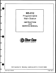
1
CS-222
2-Channel Main Station
INSTRUCTION MANUAL
*il I
Clear-m r e
OF intercom Systems
0
4065 Hollis St., Emeryville, CA 94608 (510) 496-6666
© Clear-Corn Intercom Systems 810133
9/25/91 REV. A
Clear-Com CS-222 2-Channel Main Station
O
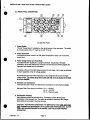
CLEAR-COM LIMITED WARRANTY
Clear-Com products are warranted to be free from defects in materials
and workmanship for a period of one year from the date of sale.
Clear-Com's sole obligation during the warranty period is to provide,
without charge, the parts and labor necessary to remedy covered defects
appearing in products returned prepaid to Clear-Com, 945 Camelia St.,
Berkeley, Ca. 94710-1484, U.S.A.
This warranty does not cover any defect, malfunction or failure caused
beyond the control of Clear-Com, including unreasonable or negligent
operation, abuse, accident, failure to follow instructions in the Manual,
defective or improper associated equipment, attempts at modification
and repair not authorized by Clear-Com, and shipping damage. Products
with their serial numbers removed or defaced are not covered by this
warranty.
To obtain warranty service, follow the procedures described below in
"Procedures for Returns" and "Shipping to Manufacturer for Repair or
Adjustment."
This warranty is the sole and exclusive express warranty given with
respect to Clear-Com products. It is the responsibility of the user to
determine before purchase that this product is suitable for the user's
intended purpose.
Any and all implied warranties, including the implied warranty of merchantability are limited to the duration of this express limited warranty.
Neither Clear-Com nor the dealer who sells Clear-Com products is liable
for incidental or consequential damages of any kind.
Return Shipping Instructions
Procedures for returns:
--If repair is necessary, contact the dealer where the unit was purchased.
--If repair through the dealer is not possible, contact the Clear-Com
Customer Service Department, located at the factory, as directed
below. They will issue a Return Authorization Number (RMA).
--Do not return any equipment to the factory without first obtaining a
Return Authorization Number.
--Be prepared to provide your company's name, address, phone number,
name of person to contact regarding the repair, type and quantity of the
equipment, description of the defect, and the equipment serial
number(s).
Questions regarding returns for repair should be directed to:
Customer Service Department
Clear-Com Intercom Systems
4065 Hollis Street
Emeryville, California 94608-3505
Telephone: (510) 496-666
Fax: (510) 496-6699
11/90 Rev. 1.0
Page 2
Clear-Com CS-222 2-Channel Main Station
Shipping IQManufacturer f
Repair
lr j l
aimmnt
All shipments of Clear-Com equipment must be prepaid via United
Parcel Service or the best available shipper. The equipment should be
shipped in the original packing container; however, it the original container isnot available, use a suitable container that is rigid and of adequate size: ifa substitute container is used, the equipment should be
wrapped in paper and surrounded with at least four inches of excelsior or
similar shock-absorbing material. A detailed description of the problem
or work to be done should be included. All shipments should be directed
to the attention of the Customer Service Department and must include
the Return Authorization Number.
Upon completion of repairs, equipment will be returned collect via United
Parcel Service or other specified shipper.
NOTICE ABOUT SPECIFICATIONS
Performance specifications included in this manual are design-center
specifications and are included for customer guidance and to facilitate
system installation. Actual operating performance may vary.
BEFORE YOU BEGIN ...
To get the most out of the CS-222 Main Station, read this manual
carefully. Itwill answer questions you might have about the operation
and service of the components in the system. Included is a Troubleshooting Section that provides causes and possible solutions to problems you
might have with system and component operation. Clear-Com's Customer Service Department is available to answer questions not covered
in this manual.
It is assumed you are familiar with the operation of basic intercom
systems. Ifyou are not, it is important to read the section titled "The
Clear-Com Concept".
11/90 Rev. 1.0
Page 3
DESCRIPTION / Clear-Corn CS-222 2-Channel Main Station
O
SECTION 1
DESCRIPTION OF THE CS-222 2-CHANNEL INTERCOM STATION
CLEAR-COM CONCEPT
Clear-Com is a closed-circuit intercom system that consistently provides high-clarity
communication in high-noise and low-noise environments. A basic system consists of a
single- or multi-channel power supply or main station connected to various single- or
multi-channel remote stations, such as beltpacks and loudspeaker stations.
Clear-Com manufactures a wide variety of both portable and fixed-installation units. All
are compatible with each other. Clear-Com intercom systems can also interface with
other communication systems and devices.
Clear-Com stations are interconnected with two-conductor, shielded microphone cable,
using 3-pin XLR connectors. One wire carries the DC power (28-30 volts) from a main
station or power supply to all remote stations, and the other wire carries 2-way (duplex)
audio information. The shield acts as a common ground. One termination (per channel)
Is needed throughout the intercom network, and is usually located in the main station or
power supply.
Clear-Com is a distributed amplifier system; each main and remote station houses its
own mic preamplifier, headset or speaker power amplifier, and signaling circuitry. The
Automatic Headset Detection circuit shuts off a station's mic pre-amp when the headset
is disconnected, so background noise on the line is not increased by an unused yet online station. Low-impedance mic input lines (200 Ohms) and specially designed circuitry
make Clear-Com channels virtually immune to RFI and dimmer noise.
Clear-Com main stations, power supplies and certain remote stations each have an
auxiliary program input with its own volume control, which allows an external audio
source to be fed to the intercom system.
Visual Signal Circuitry (CALL Lights), a standard feature on most main and remote
stations, allows the user to attract the attention of operators who have removed their
headsets.
Depending upon the type of main and remote stations selected and assuming that
enough DC power is available, a maximum number of remote stations from 10 (all
speaker stations) to 30 (all headset stations) can be distributed along a mile of wire.
Remote stations bridge the intercom line at a very high impedance (>10 KOhms), and
place a minimum load on the line. The audio level always remains constant, and does
not fluctuate as stations leave and join the network.
The 28-30 volts DC provided by main stations and power supply units enable remote
stations to operate with minimal current (25 mA. quiescent for headset stations, 50 mA.
quiescent for speaker stations) while generating extremely loud listen volumes (greater
than 110dB SPL using Clear-Com Headsets). The highervoltageand lowcurrent keep
voltage losses to an absolute minimum in long lines. If the supply voltage drops due to
the addition of great length of cable or many more stations, Clear-Com equipment will
continue operating with less than 12 volts available.
0
2/92 Rev. 1.1
Page 4
DESCRIPTION / Clear-Com CS-222 2-Channel Main Station
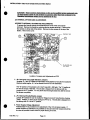
1.1 CS-222 OVERALL DESCRIPTION
The CS-222 is a portable, two-channel main station with a regulated power supply and a
versatile monitoring system. Itfeatures excellent speech intelligibility in all noise-levels.
The CS-222 contains a mic preamp with a limiter. The CS-222's four-watt power amp
can drive a standard Clear-Com headset to levels greater than 110 dB SPL.
The CS-222 provides DC voltage and the ability to talk & listen on two separate
channels. It supports and monitors two intercom lines containing as many as 30 remote
head-set or 6 remote speaker stations.
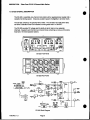
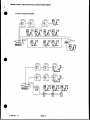
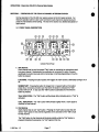
CLEAR-COM
N~~~
~2*0
.00
'
i.
lPw
113
Ran
ax
ulm
0
ato.
_
amo
~_
WO%±
a m
__
CS-222 Front Panel
CS 222 Rear Panel
_
A
se
r-_5
on jf~~~lm
N~~~hWo
L~~~~~~~~~~~I
PAd L.
CS-222 Block Diagram
11/90 Rev. 1.0
Page 5
Ad
M
_M
DESCRIPTION / Clear-Corn CS-222 2-Channel Main Station
Monitoring System
The front panel of the CS-222 has one headset connector for use by the operator.
The operator monitors the intercom channels turning up the appropriate "Listen Level"
volume controls (one for Channel A, one for Channel B). Either channel may be
monitored separately, or both simultaneously (without tying the two channels
together). These volume controls are always active regardless of "Talk" channel
selection on the station.
The jack marked "Earphone" is connected in parallel with the earphone circuit of the
headset connector. It can be used for monitoring or recording.
DualkActUon DX Buttons
Each channel has its own "Talk" button which can either "Latch" on, or operate
momentarily.
Pressing the button quickly will "toggle" the "talk" function, alternately turning it on or
off.
The "Talk" button will illuminate dimly when activated.
Stage Announce (Paging)
The "STAGE ANNOUNCE" button on the front panel sends the signal from the
operator's headset microphone preamp to the balanced, line-level Stage Announce
output on the back panel.
The Stage Announce button also mutes the operator's voice output to the intercom
channels. This mute function can be defeated with an internal user selectable jumper.
The "STAGE ANNOUNCE" button also activates a SPDT from "C" relay when
pressed. The 1 amp contacts can be used for any user desired control function (i.e.
muting a local monitor speaker).
Call Sianaling
Visual "Call- Signaling attracts the attention of people who have removed their
headsets or turned off their speakers. The CS-222 front panel provides a "Call"
button for each channel. Pressing the desired channel button turns on the "Call"
lights at all stations on that channel. The "Call" is active regardless of talk status.
When a remote station sends a Call signal, the lamp in the 'Talk" button associated
with that station's channel lights brightly, whether or not the channel is selected.
Program Input
The CS-222 accepts a balanced, mic-level or line-level program input which can be
monitored in the headset. Program volume for the operators headset is adjustable
with the "Program Monitor knob on the front panel.
The external program is also assignable and adjustable in level to either or both
channels, and mixes with the Intercom signal. The program feed can be set to be
interrupted by the "TALK" for a particular channel.
Skietone
0
The "Sidetone Adjust" controls for each channel on the front panel allows adjustment
of the operators own voice as heard in the headset.
11/90 Rev. 1.0
Page 6
DESCRIPTION / Clear-Corn CS-222 2-Channel Main Station
LINKino Channels Taethe
A front panel switch is provided that allows the operator to instantly connect channel A
and channel B together for a combined intercom system consisting of both channels.
Reonte Mk-Kill Function
The CS-222 provides the ability to turn off any open-mics on Series 500 belt-pack
remote stations. Momentarily pressing the Channel A RMK button will remove the
DC power from both channels clearing the 'talk' function of all the belt-packs.
Power Sunnlv Protetion
The CS-222 power supply Is regulated, current-limited, and provides 30 volts DC at
I A from a 11 5V or 230V (selectable) AC mains supply. The CS-222 has an
automatic short-circuit sensor to protect the system from miswired cable or shorts in
the lines or general current overload. If a short occurs, the red LED on the front panel
marked "Short" illuminates. Removing the short, will cause the power-supply to reset
itself automatically within 5seconds
Sysem TEerminaio
The CS-222 provides individually selectable audio termination networks for both
channels A and B.
Portabilit
The unit is light-weight, weather-resistant, and assembled with a sturdy plastic
carrying strap and four protective rubber feet.
Easy Interconnection
The CS-222 provides three 3-pin, male XLR outputs for Channel A (connectors are
wired in paralleD and three for Channel B. Intercom signals are fed from the CS-222
with standard mic cable (see next section).
E
xSystem Expanon
The CS-222 can be ganged together with other CS-222's or other Clear-Coin powersupplies for multiple two-channel systems and back-up power support.
The CS-222 isavailable with a rack-mount kit for adapting it to standard 19"
equipment racks. The Clear-Com part number for the CS-222 Rack-Mount Kit is
RK-101.
05192 Rev. 1.1
Page 7
DESCRIPTION / Clear-Com CS-222 2-Channel Main Station
O
1.2 TECHNICAL SPECIFICATIONS:
MICROPHONE PRE-AMP:
--Dynamic Headset Input: ------------------------ Input Impedance - 1 KOhms
Input Level - -55 dBv* nominal
Input Level - -10 dBv* max.
--Frequency Response: --------------------------- 250 Hz to 12 KHz, contoured for intelligibility.
--Limiter Range: ---------------------------20 dB
--Gain from Headset to intercom Line: --------- +41 dB
HEADPHONE AMPLIFIER:
--Load Impedance: --------------------------------- 50-2000 Ohms
--Output Level: --------------------------------------- at least +20 dBv* across 600 ohm
--Distortion: ----------------------------------------- <0.2% THD at 1 KHz
--Frequency Response: -------------------------- 200-18KHz +/-2dB
--Gain from Intercom Line: ------------------------- +37 dB
PROGRAM INPUT:
--Input Level Ref.: ------------------------------------ -65 dBv* (mic) -15 dBv' (line)
--Input impedance: ------------------------------- 1 KOhms (mic) >100 KOhms (line)
--Frequency Response: --------------------------- 150 Hz to 18 KHz
INTERCOM LINE DRIVE/RECEIVE CIRCUITS:
--Impedance, Output Load: ---------------------- 10 KOhms (200Hz - 10 KHz)
--Level, Line (200 ohm load): --------------------- -9 dBv* (nominal) +5dBv (max before clip)
--Sidetone Null Capability: --------------------> 25 dB (200Hz - 10 KHz)
--Crosstalk, Station Induced Ch. to Ch.: -- >-60 dB
--Noise, SN Ratio in Listen Channels: ---------- >60 dB
INTERCOM SYSTEM SPECIFICATIONS (STANDARD CLEAR-COM):
Usable Line Quality: up to 100 Stations and 5000 feet of line.
Crosstalk: For 2 lines terminated at one end the crosstalk at the far end shall be: 500 ft <
-52dB
POWER SUPPLY:
--Output Voltage: - --+30 Volts
--Output Noise: ---------------------------------------- < 1 mili volt AC RMS
--Current limit: -----------------------------1.0 A
CONNECTORS:
--Intercom: ------6 XLR-3 (3-CH A, 3-CH B)
--Program: --------…----- XLR-3F
--SA: -------------------------------------------------- XLR-3M
AC POWER REQUIREMENTS: ---------------- 105-125/210-250 VAC, 50 to 60 Hz, 60 VA
PHYSICAL SPECIFICATIONS:
--Dimensions: ----------------------- 8.125"W x 3.0"H x 10.0D (206mm x 76mm x 254mm)
--Weight: ---------------------------- 5.2 lbs (2.3 Kg)
WORKING TEMPERATURE RANGE: -------- 32-122' F (0-50' C)
*
* - OdBv is referenced to 0.775 volts RMS.
Specifications subject to change without notice.
11/90 Rev. 1.0
Page 8
INSTALLATION I Clear-CoM CS-222 2-Channel Main Station
SECTION 2
INSTALLATION OF THE CS-222 2-CHANNEL MAIN STATION
2.1 INSTALLATION OVERVIEW
The CS-222 is a combination of a very versatile intercom station and a system power
supply. Installations can vary depending on what features are used.
The fundamental concept of Clear-Com Party-Line intercom isthat all stations
provide high impedance current sourced signals into a single common system
termination. The line drivers in a station have a source impedance greater than 10
KOhms.
The termination of an intercom line (or channel) is a220 Ohm resistor in series with a
4.7 KOhm that is paralleled with a 10 uF capacitor. The impedance of the network at
audio frequencies is 220 Ohms. The DC resistance of the network is 5 KOhms. The
high DC resistance allows a CALL voltage to be placed on the line without drawing
too much current. A CALL signal is a DC voltage greater than 10 volts on the line.
The DC source for this CALL signal is also a current source there by providing a high
impedance and not affecting the audio signal.
The receive or "listen" section of stations contain a 'hybrid null' circuit that attempts to
reject (null) any "talk" signal being sent by that station on that channel. The 'hybrid
null' circuit depends on a known impedance on the intercom line to accomplish this.
Variations in impedance on the line upset the 'null'.
Clear-Corn main and some remote stations provide switch selectable termination
networks on all intercom output lines. It is up to the user to determine where the
termination will be provided. An unterminated line will cause excessive levels,
possible oscillation of line drivers, and sever unbalance of hybrid null networks. A
double or multiple terminated line will cause low levels and sever unbalance of hybrid
null circuits.
CAUTION: All Clear-Corn Intercom lines must be terminated. Care must be taken
not to fall to terminate or to 'double' terminate a line. All unused intercom inputs
must be terminated to keep the line drive circuits stable.
CLEAR-COM STATION TYPES:
Clear-Corn party-line intercom stations all fall into one of four distinct categories that
relate to system powering and termination. The four types are as follows:
A. MAIN STATION:------ Supplies system power for external stations.
Provides switch selectable terminations.
B. MASTER STATION: - Contains a power supply just for itself.
- Provides switch selectable line terminations.
C. REMOTE STATION: - No power supply. Derives power from the Intercom line.
- May or may not have terminations.
D. POWER SUPPLY: --- Supplies system power for external stations.
--- Provides switch selectable terminations.
11/90 Rev. 1.0
Page 9
INSTALLATION I Clhar-Corn CS-222 2-Channel Main Station
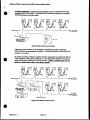
SYSTEM POWERING: Typical Clear-Com systems consist a a MAIN STATION and
multiple REMOTE STATIONS. The REMOTE STATIONS are powered from the MAIN
STATION through the Intercom cable.
RS-501
CC-75B
RS-501
CC-75B
RS-SO1
CC-75B
RS-5O1
CC-758
TERMINATONS ON
TO OTHER
LEL . ACKS
222/~~~~~~~~~~~~~B
111A11'
Typical Single Power Source System
Clear-Com power supplies can be paralleled to Increase the number of REMOTE
STATIONS that can be operated in a system. The CS-222, MS-222, and the PS-22 will
provide I A of current.
By simply connecting a PS-22 or another CS-222 in parallel with an existing CS-222 the
current capacity of the system Is raised to 2 A. The termination switches in the second
power source would need to be in the OFF position. NOTE: h fKfunction sllno
woNk on 1 system IBM haa tw
RS-501
CC-75B
r more
RS-501
ower sunnliesn
CC-75B
RS-5O1
CC-756
RS-501
CC-75B
TERMINATIONS ON
BELTPACKS
RS-5O1
CC-7SB
OR
CC-75B
TO OTHER
BELTPACKS
OR PRODUCTS
PS-22
TERMINATIONS OFF
System With Multiple Power Sources
05/92 Rev. 1.1
RS-501
Page 10
INSTALLATION / Clear-Com CS-222 2-Channel Main Station
2.2 CABLE CONSIDERATIONS:
The Clear-Com intercom line is intended to run on a shielded twisted pair of cable per
channel of intercom. One conductor carries full duplex ("two-way") audio, the other
conductor carries the DC power for remote stations. The shield is used for ground
return for audio and power. When choosing interconnect cable, keep the following
considerations in mind:
1. DC resistance of the ground or common conductor affects crosstalk. For runs
longer than 100 feet do not use wire smaller than 20 gauge. The total
resistance of the ground return (the combined parallel sum of all shields to a
location) to any point in the system should be under 1.5 ohms.
2. The capacitance of the interconnect cable affects system frequency response and
side-tone stability. Total capacitance should not be greater than 0.25 uF
(capacitance between conductor and shield) equivalent to an intercom system
containing 5000 feet of cable at 50 pF per foot.
PORTABLE INSTALLATION CABLE
Typical cable for portable system interconnections is flexible, two-conductor, shielded
microphone cable. For runs less than 500 feet a cable made of 24 gauge wire is
acceptable. For runs longer than 500 feet use a 20 gauge cable or larger.
Portable remote stations such as beft-packs have a pair of input and output
connectors; when installing a system that includes these, they can be "daisy-chained"
or "loop-thru" connected along one interconnect path. Clear-Com provides a one
input by three output Line-Splitter (OP-100) that can also simplify wiring. DaisyChaining and Line-Splitting decreases the amount of cable required and simplifies the
installation.
PERMANENT INSTALLATION CABLE
Vinyl-jacketed shielded pair is the cable of choice for permanent installations. Use a
low-capacitance 20 gauge wire for short runs (under 500 feet) and 18 gauge cable for
runs greater than 500 feet. Placing the cable in conduit is recommended but not
necessary.
Multi-pair cable that is individually shielded is acceptable for use in multi-channel
systems. For cross-talk considerations the shields must be tied together on both ends
of the cable to produce the lowest possible DC path for ground return.
11/90 Rev. 1.0
Page 11
INSTALLATION / Clear-Com CS-222 2-Channel Main Station
*
2.3 REAR PANEL DESCRIPTION
CIL
SS
CS-222 Rear Panel
1. Power Swltch
The AC "Power Switch" is located on the top left corner of the rear panel. The switch
is a rocker switch with a "1"n mark for on and "0"for off.
i
w
2. Power Connector
Just below the power switch is an EIA power receptacle for either 115 or 230 VAC
~~~power input.
~~3. Power Voltage Select and Fuse Block
Just below the EIA receptacle is a plug-in fuse block. By placing a flat blade
screwdriver in the slot between the connector and the block and twisting slightly the
fuse block will release from the connector.
Complete removal of the block will give access to both fuses. Both fuses are identical
in value regardless of the AC voltage applied.
By turning the block over when replacing it in the receptacle will convert the input
voltage range. lii yvllgta range that ini sad rigflt aide un Ibottomni
of a bflc
inIbnt winf selected
4. Intercom Line Connectors
There are two sets Of three XLR-SM intercom connectors for both channel outputs.
Standard Clear-Corn wiring is as follows: Pin 1 -- Ground
Pin 2-- +30 VDC
Pin 3 - intercom Audio
5. Termination Switches
Each intercom channel is provided with a 'Termination" switch allowing easy
termination of the intercom line. The switch isprovided in case there are multiple
MAIN stations connected to the inter-corn line.
0
CAUTION: FOR PROPER OPERATION IT IS IMPERATIVE THAT QMJAND OLY
DUE TERMINATION BE PRESENT ON ACLEAR-COM INTERCOM LINE. CLEARCOM LINE DRIVERS DEPEND ON A KNOWN LOAD VALUE FOR PROPER
OPERATION.
11/90 Rev. 1.0
Page 12
INSTALLATION / Clear-Corn CS-222 2-Channel Main Station
6. Announce Output Connector
The "Announce" output is a XLR-3M. The output is transformer isolated, 600 ohms
output impedance, and has an output level of approximately 0 dBv.
Wiring is as follows: Pin 1 -- Ground
Pin 2 --- Audio
Pin 3
-- +Audio
7. Announce Relay Contact Terminals
The "Announce" relay contacts are available on a screw terminal block. The relay
contacts are "Form C" (break before make). The contact description is as follows:
Left most ---- N/O --- Normally Open Contact
Center ------- C --- Wiper
Right most -- N/C --- Normally Closed Contact
8. Program Input Connector
The "Program" input is a XLR-3F. It is an electronically balanced (differential) input.
Wiring is as follows: Pin 1 -- Ground
Pin 2-- -Audio
Pin 3 - +Audio
9. Program Gain Switch
The "Program Input Gain Switch" is located next to the "Program Input" connector.
Inthe "Mic" position the input will accept a 'low' impedance dynamic microphone and
produce a usable level from a -65 dBv input signal for monitor and intercom line feed
uses.
Inthe "Line" position the input presents a balanced high impedance and a -15 dBv
input signal will produce a nominal intercom level on an intercom line.
11/90 Rev. 1.0
Page 13
INSTALLATION / Clear-Com CS-222 2-Channel Main Station
'CAUTION These servicing Instructions am usr
by nualified service personnel onl
at AmiX electric shock
t
d nat erfofnMy servicing hor than tat contained in ft
Qaurating Insrutlnions
unless u AM nualifled
lt do s2,a
2.4 INTERNAL OPTIONS AND ADJUSTMENTS
ACCESS TO INTERNAL OPTIONS AND ADJUSTMENTS:
To access the internal options and adjustments the cover of the unit must be
removed. Remove the handle by removing the two screws securing R. Remove the
two screws on either side of the station. Remove the two screws on the top of the
station. Remove the cover.
2COMPONENT SIDE
CS-222 PCB MAIN
170150
~~~~~~~~~~~~~~~~~~P/N
Location of Jumpers and Adjustments on PCB
1. JP-1 and JP-2 Line Length Selection Jumpers
Jumpers JP-1 and JP-2 allow the optimization of the hybrid null circuitry for excessive
intercom cable lengths. JP-1 isfor channel A and JP-2 is for channel B.
The "S"position of the jumpers isfor 'short' lines (200 - 500 feet). The "L"position is
for lines in excess of 500 feet. The CS-222 isshipped from the factory with the
jumpers in the "L" position. For very short total line lengths (less than 200 ft) remove
the jumper completely.
2. JP-3 Interrupt Enable/Disable Jumper
Jumper JP-3 allows the user to enable the "Stage Announce" mute function of active
"Talks". Position "Y' is for yes to muting and "Nu for no. The CS-222 is shipped from
the factory with JP-3 in the wY position.
0
3. Power Supply Voltage Adjustment
Potentiometer P3 is provided for trim adjustment of the +30 volt power supply. If
power supplies are intended to be paralleled on the same line their outputs should be
as close as possible to each other for proper sharing of current.
11/92 Rev. 1.2
Page 14
INSTALLATION / Clear-Com CS-222 2-Channel Main Station
F
2.5 INTERCONNECTION SETUP
0
After determining system configuration and channel assignment, pick a location for the
CS-222; it can be anywhere as long as it is provided with a source of AC power. Check
the Power Block on the rear panel for the proper AC voltage range. See section 2.3 on
the page 12 if it needs changing.
1. Use standard shielded mic cable (see section 2.2). ALWAYS AVOID SHARP
BENDS IN THE CABLING; ALLOW AT LEAST 3 inches behind rack-mount
units for cable extending from rear panels.
2. Route all cables from the Main Station to the Remote Stations. Pin
assignments on ALL 3-pin intercom connectors are:
Pin 1 -- Common
Pin 2 - +30 Volts DC
Pin 3 - intercom Audio
3. Route cables away from heavy AC power sources, such as lighting panels,
electric motors, or power transformers.
4. In permanent installations, BE SURE TO INSTALL THE SYSTEM IN
ACCORDANCE WITH APPROVED LOCAL BUILDING CODE.
5. If program monitoring is required, connect the external signal to the Program
Input (3-pin female) connector on the CS-222 rear panel. The station
operator can hear the program in the headset mixed with intercom activity or
the program can be sent to either intercom line. The program pre-amp's gain
is switch-selectable (on the rear panel) for either mic level (-65 dBv nominal
input signal) or line-level (-15 dBv nominal). The input is balanced and the
impedance is 100K Ohms in the line position, 600 Ohms nominal in the mic
position.
6. If the Stage Announce function is to be used, connect to the Announce Output
(3-pin male XLR) connector on the CS-222 rear panel. This output is
transformer balanced, 600 Ohms impedance, and an output level of 0 dBv. If
the output is to be used as an unbalanced source connect one side to
common (pin-2 to pin-1).
If the SA relay is to be used, connect lo the appropriate screw lug terminals
(NO or NC) depending on what action is needed for the external equipment
to be controlled. The relay is a form C, Break before Make, contact. NOTE: the
contact rating of the relays are 1A resistive at 24 VDC or 1/2A resistive
at 120 VAC.
7. Turn on power switch on the rear panel. The GREEN Power led on the front
panel should illuminate. Plug in a headset, and set intercom, Program, and
Sidetone levels as desired.
NOTE ABOUT HEADSETS: The following is a description of a recommended headset.
Mic Type ----- Dynamic Wiring:
Impedance -- 150-250 Ohms
Output -------- -55dB
Headphone -- Dynamic
Impedance --- 50-2000 Ohms
11/90 Rev. 1.0
Pin 1 -- mic common
Pin 2-- mic hot
Pin 3 -- headphone common
Pin 4 -- headphone hot
Page 15
0
INSTALLATION / Clear-Com CS-222 2-Channel Main Station
TYPICAL CS-222 SYSTEMS:
K9-111A
K9-1-1A
KS-11iA
RS C 75
R
9
CC-75B
RS-502
RSd
11/90 Rev. 1.0
Page 16
KB-lilA
CC-7YI
-2
RS-70
0VO50
CC-7-I
C-2
MRW2C-22
OPERATION / Clear-Com CS-222 2-Channel Main Station
SECTION 3 / OPERATION OF THE CS-222 2-CHANNEL INTERCOM STATION
Normal operation of the CS-222 only requires access to the front panel controls. For
intercom operation set the Listen Level controls for each channel to desired level and
press the Talk switches when talking. The rest of this section is a detailed description of
each control.
3.1 FRONT PANEL DESCRIPTION
CS-222 Front Panel
1. Talk Buttons
Each channel has its own illuminated "Talk" button for activating the microphone feed
to a given channel. Mechanically the pushbutton is momentary in action, however
electrically the button has dual action (momentary or latching) depending on how the
button is pressed.
LATCHING: Pressing the button quickly will "toggle" the "talk" function, alternately turning it on or
off.
MOMENTARY: Pressing the button for longer than 1/4 second will turn the button
press into a momentary function such that when the button Is released the "Talk'
function will turn oft. In any case the "Talk" function is activated all of the time the
button is pressed.
TALK INDICATION: The 'Talk" button will Illuminate dimly indicating when a "Talk" is
activated.
CALL INDICATION: The 'Talk" button will illuminate brightly when a "Call" signal is
received on that channel.
2. Call Buttons
Each channel has its own "Call" button. Pressing the "Call" button at any time will
send a "Call" signal on that channel regardless of the activation of the "Talk" circuit
for that channel.
The "Talk" button for that channel will illuminate brightly while the "Call" button is
pressed indicating the presence of a "Call" signal on the line.
11/90 Rev. 1.0
Page 17
OPERATION I Clear-Corn CS-222 2-Channel Main Station
0
3. Listen Level Controls
Each channel has a separate "Listen Level" control. Listening Is always on and Is not
controlled by any logic. To listen to a channel, turn up the appropriate control. To not
listen to a channel, turn the control completely off.
4. Side Tone Controls
Each channel has a "Side Tone" null control. This control is used to set the amount of
the microphone that is heard Inthe earphone from that channel.
This control Is a true hybrid null control and therefore is sensitive to changes in line
loading. For headphone use it is best to find the 'null' for a given channel and then
rotate the control clockwise to obtain the desired side tone level.
If an external speaker Isused providing a possible acoustic feedback path it will be
necessary to use an almost complete 'null' of the side tone control.
5. Remote Mic Kill Buttons
It sometimes becomes desirable Inan Intercom system to turn off all open microphones
in a system. Clear-Com Series 500 beltpacks have the feature that if the DC power to
the pack is removed momentarily, the microphone "Talk" circuits will be turned off.
Pressing and holding the RMK button for several seconds will reset all open
microphones at all Series 500 beltpacks on that channel.
CAUTION: RMK CANNOT be used if power for a channel is derived from some
place other than the local station. The RMK action momentarily shorts the power line
of the affected channel. fiK Dily works fm a single MAIN station system,
6. Program Enable Switches
The CS-222 has the ability to feed an external program signal to either of the two
channels independently The "Program Enable Switch" allows the program to be
turned ON, OFF, or ON with INTERRUPT.
Inthe ON position the program Isfed to the channel under all conditions.
Inthe OFF position the program isnot fed to the channel.
In the INT position the program isfed except when a "Talk" isactivated to the
channel. This "Program Interrupt" or IFB" function can be used for talent cueing and
dressing room show monitor applications.
7. Program Send Level Controls
Each channel has a "Program Send Level" control that sets the amount of program
being sent to that channel when the program is activated.
8. Headset Connector
The "Headset" connector is a XLR-4M wired for standard Clear-Com headsets.
MICROPHONE: The CS-222 is intended to work with a dynamic microphone of about
200 ohms
HEADPHONE: The CS-222 isdesigned to drive a 50 to 1000 ohm headphone.
Clear-Com headsets are 400 ohms for the singl muff and 200 ohms for the dual muff.
05192 Rev. 1.1
Page 18
OPERATION / Clear-Com CS-222 2-Channel Main Station
9. Earphone Jack
The jack marked "Earphone" provides an output intended to drive an extra earphone.
This output iscapable of driving an 8 ohm headphone or loudspeaker.
10. Link Switch
The switch marked "Link" on the right side of the unit allows the operator to "combine"
channels A and B so that all stations can talk to each other. (Normally channels A and
B are totally isolated and stations on one channel cannot talk to stations on the other
channel.) When in the "A+B Link" operating mode, only the channel A controls
operate. The channel Bcontrols have no effect.
NOTE: When the switch is in the "A+B" position the channels do not actually
'combine'. What really happens isthe three B channel connectors are simply
internally disconnected from the B circuitry and connected to the A channel circuitry,
putting all stations on the channel A party-line. This maintains all the correct line and
station terminations.
CAUTION: The LINK function will work properly at the main station that isproviding
the "line terminations" for the system. Ifthere is more than one Main Station in the
system equipped with a "LINK" switch, DO NOT ATTEMPT TO USE THE LINK
SWITCH ON THE STATIONS THAT ARE NOT PROVIDING THE LINE
TERMINATION. Both double line termination and station un-termination will result,
causing significant sidetone mis-adjustments and possible feedback and oscillation.
11. Program Monitor Control
The "Program Monitorm volume control sets the amount of the program signal heard
directly in the headphone. This control only affects what is heard in the headphone
and does not affect "Program" feed to the intercom lines.
12. Stage Announce Button
The "Stage Announce" (SA) button allows the operator to instantly use the
microphone input to directly talk to a system external to the intercom such as a paging
speaker/amplifier in another room. A dry set of relay contacts on the rear panel is
also available that can be used to activate external switching as needed when the
"SA" button is pressed.
Pressing the SA button momentarily disables any active "Talks". Active "Talk' circuits
will be restored when the button is released. The "Talk" muting action can be
defeated ifdesired by moving an internal jumper. (see section on internal options and
adjustments)
11/90 Rev. 1.0
Page 19
OPERATION / Clear-Corn CS-222 2-Channel Main Station
13. Power Supply LEDs
There are two power supply status LEDs in the lower right hand corner of the front
panel.
NORMAL OPERATION: The GREEN LED is on by itself.
OVERLOAD CONDITION: ifthe RED LED is on and the GREED LED pulses on shortly
about every five seconds, the load is in excess of 1 ampere but there is not a direct
short on the line.
SHORT CONDITION: ifthe RED LED is on and the GREEN LED does not pulse on, the
power line has a direct short on it.
Lowering an excess load or removing a short will allow the automatic reset circuit to
attempt to reset the power supply about once every four seconds, to restore normal
operation to the power supply without operator intervention.
SECTION 4 / TROUBLESHOOTING THE CS-222 2-CHANNEL INTERCOM STATION
Symptom #1: System is non-operable: GREEN power led is not illuminated and the RED
short led is not illuminated.
*
CAUSE: Loss of AC power.
REMEDY: Plug unit into dependable AC source.
CAUSE: Fuses could be blown.
REMEDY: Replace fuse(s); If it blows repeatedly, probably the power supply has
internal component failure.
Symptom #2: The RED short led stays illuminated without the GREEN led pulsing on
periodically.
CAUSE: Shorted or mis-wired intercom cable.
REMEDY: Remove cables, one at a time, from Main Station until faulty line Is located.
Check for shorts between pins 1and 2. When removing a possible short
wait for several seconds to see if the automatic reset will clear itself.
CAUSE: Defective Remote Station.
REMEDY: Check Remote unit.
Symptom #3: Excessive back-ground noise pick-up by microphone.
CAUSE: Distance from mic to mouth is too far.
REMEDY: Move closer to mic.
CAUSE: Too many mics on in entire system.
REMEDY: Turn off all unused mics. RMK can be used to kill all Series 500 belt-pack
open mics.
*
CAUSE: Volume too high.
REMEDY: Lower headset volume.
11/90 Rev. 1.0
Page 20
TROUBLESHOOTING / Clear-Com CS-222 2-Channel Main Station
Symptom #4: Hum or buzz in system.
CAUSE:
inductive pickup caused by close proximity of Main or Remote station to
power lines or transformers.
REMEDY: Relocate offending unit.
CAUSE: 10 Ohm chassis ground resistor (R224) isopen.
REMEDY: Check the DC resistance for 10 Ohms between the chassis and pin-1 of
any intercom connector. R224 is located on the Rear Panel Connector
Printed Wiring Board. If this condition happens It Is because the
system ground came In contact with something "Hors with respect to
the Main Station Earth ground. Should this occur, we recommend
you carefully check the system ground and AC distribution In the
area.
NOTE: THIS IS A POTENTIALLY DANGEROUS SITUATION; IF IT
OCCURS, A SHOCK HAZARD MAY EXIST BETWEEN THE METAL
BOOM OF A HEADSET AND GROUND.
CAUSE: inductive pick-up by headset mic; check by switching mic on and off.
REMEDY: Move mic away from "hum field".
Symptom #5: System feedback.
CAUSE:
REMEDY:
REMEDY:
REMEDY:
REMEDY:
REMEDY:
Acoustical.
Volume too high at one station.
Two or more speaker stations have mics on simultaneously.
Headset-mis-wired. Rewire headset connector.
Headset laying on table and microphone on. Turn mic off.
Headset quality. Some headsets have poor isolation between the
microphone and earphone. Adjust sidetone.
CAUSE:
REMEDY:
REMEDY:
REMEDY:
Electrical.
Check Termination.
Check sidetone levels.
A headset extension cord was used. Headset extension cords must be
used with great care and are not recommended.
Symptom #6: Audio sounds low and distorted and the Call light stays on.
CAUSE: An ultrasonic oscillation is present.
REMEDY: Headset mis-wired. Rewire headset connector.
REMEDY: A headset extension cord was used. Headset extension cords must be
used with great care and are not recommended.
11/90 Rev. 1.0
Page 21
PARTS LISTING / Clear-Com CS-222 2-Channel Main Station
SECTION 5 / Parts List for CS-222 2-CHANNEL INTERCOM STATION
CC aF A
Descritiaon
X1.
240039
240020
240021
210233
610022
480090
480092
480112
480171
480000
480001
480005
480026
480038
480053
480172
520035
240015
240038
390005
390038
390039
810133
480012
480175
480070
480021
470019
470029
4 7 00t-1
470063
450004
240010
240058
510028
510043
510095
510094
510096
510090
510093
560015
560016
480047
480061
480069
480052
480004
480050
480008
480173
11/90 Rev. 1.0
Bracket, Hardware for Handle
Button, Red for C&K Switches
Button, Black for C&K Switches
Connector, Power Entry Module
Cord, Power
CMOS IC, MC14584B Hex Schmitt Trigger
CMOS IC, DG211CJ Quad Analog Switch
CMOS IC,4001 Quad 2 input NOR Gate
CMOS IC,4013 Dual D Type Flip-Flop
Diode, 1N4148, Signal
Diode, 1N4001, Rect. 1A 50V PIV
Diode, 1N5401, Rect. 3A 100V PIV
Diode, Zener, 1N957B 6.8V 5% .4W
Diode, Zener, 1N5231B 5.1V .5W
Diode, Zener, 1N5245B 15V .5W
Diode, Zener, 1N5251 B 22V 5% .5W
Fuse, 1/4A SLO-BLO 20MM
Knob, Volume with 1/8" shaft
Handle, Black
Lamp, Incandescent EL3522 (Talk SW)
LED, Red Square (Short LED)
LED, Green Square (Power Good)
Manual, Instnuction
OP-AMP, LM384 Power
OP-AMP, LM833A Dual Low Noise
OP-AMP, NE5532 Dual Low Noise
OP-AMP, NE5534A Low Noise
POT, 50K Trim Vert. PC Mount (Prog Lev.)
POT, 2K Trim Horz. PC Mount (Volt Adj.)
POT, 50 PC Mount (Volume)
POT, 5K Trim Horz. PC Mount (Sidetone)
Relay, SPDT 24VDC
RubberFoot
Shaft, Trimpot (Sidetone)
Switch, SPDT Pushbutton (Stage Announce)
Switch, SPDT Pushbutton (Call)
Switch, SPDT Pushbutton 6A (RMK)
Switch, SPDT Toggle (Link)
Switch, SP3T Toggle (Program)
Switch, DPDT Slide (Term. & Prog Gain)
Switch, 4PDT Illuminated Pushbutton (Talk)
Transformer, Audio (Stage Announce)
Transformer, Power
Transistor, 2N4401
Transistor, 2N5486 N Channel JFET
Transistor, 2N5639 N Channel JFET
Transistor, MPS-A05
Transistor, MPS-A13
Transistor, MPS-A55
Transistor, MPS-A63
Transistor, MTA30N06EL Power MOSFET 60V 30A
Page 22
2
2
3
1
1
1
1
1
1
22
1
4
2
1
1
1
2
3
1
2
1
1
1
1
1
4
1
2
1
3
2
1
4
2
1
2
2
1
2
3
2
1
1
2
1
1
5
6
3
2
1
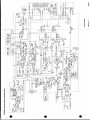
r--------~
~
~
- -Lf
~~-----
IL1
- ---AA
as
~~~~~~~~~~~~~~------
----
---------
gS
----
----
t
O' ark
Y - ----
fV
---
-
i
i
CH
2iS 9
0
>--
N T
U;~~~~~~~~~
WN' HW
~~~~~~~~~~~~~~~~~~~~~~~~~~~~~~~~~~~~~~~~~~~C
|Lady,,.
s4S¢1,,4~~~~~~~~
8
p|
$
t
;
S~~a
vp
os BS tYX__
|~~~d
i~~~~~~~~~~~~~~~~~~~~~~~~~~~~~~H
s,
of~~~~~~~~~~
_
>0-
.~~~~~~~~~
_
_~~~~~~~~~~~~-