1
Cisco 12000 Series Gigabit Switch
Routers
Description
The Cisco 12000 series Gigabit Switch Routers (GSR) is a new product class of routers that perform
Internet routing and switching at gigabit speeds. The Cisco 12012 and Cisco 12008 meet the
exponential growth in demand for Internet bandwidth and bring scalability and high-performance
services to IP-based networks. Designed to meet current and future Internet traffic requirements, the
Cisco 12000 series initially supports IP backbone links at OC-3/STM-1 (155 Mbps) and
OC-12/STM-4 (622 Mbps)—facilities up to four times faster than those used today.
The Cisco 12000 series is built around a high-speed switching fabric that provides nonblocking
bandwidth to support high-performance IP-based LANs and WANs. The switching fabric is scalable
from 15 to 60 Gbps on the Cisco 12012 and from 10 to 40 Gbps on the Cisco 12008. Both the
Cisco 120012 and Cisco 12008 support IP over SONET/SDH and ATM interfaces.
The Cisco 12012 has 12 user-configurable slots, and the Cisco 12008 has eight user-configurable
slots. These slots contain line cards and Gigabit Route Processor (GRP). Network interfaces reside
on line cards that provide connection between the router’s switch fabric and the external networks.
For more information on the Cisco 12000 series, refer to the Cisco 12012 Gigabit Switch Router
Installation and Configuration Guide and the Cisco 12008 Gigabit Switch Router Installation and
Configuration Guide.
List of Terms
Cisco Express Forwarding (CEF)—An advanced Layer 3 switching technology for IP. CEF
optimizes network performance and scalability for networks with large and dynamic traffic patterns,
such as those associated with the Internet, Web-based applications, and interactive sessions.
Gigabit Route Processor (GRP)—Serves as the console for the Cisco 12000 series, handles
environmental monitoring for the entire system, and provides the line cards with routing table
updates.
Line cards—Provide connection between the router and the network and are available in a variety
of network media types (based on your order). Line cards communicate with each other and with the
GRP through the switch fabric.
Switch fabric—The circuitry that carries the user traffic between line cards or between the GRP and
a line card.
Cisco 12000 Series Gigabit Switch Routers 13
Supported MIBs
Document Conventions
Command descriptions use these conventions:
•
•
Boldface indicates commands and keywords that are entered literally as shown.
•
•
•
Square brackets ([ ]) indicate optional elements.
Italics indicate arguments for which you supply values; in contexts that do not allow italics,
arguments are enclosed in angle brackets ( >).
Braces ({ }) group required choices, and vertical bars ( | ) separate alternative elements.
Braces and vertical bars within square brackets ([{ | }]) indicate a required choice within an
optional element.
Supported MIBs
The Cisco 12000 series supports the following MIBs:
•
•
Cisco Config Man MIB
•
•
•
Cisco Flash MIB
Cisco Environmental MIB—The new ciscoEnvMonAlarmContacts MIB object in the
Environmental MIB to monitor the alarm contacts on the alarm card (for the Cisco 12012) or the
clock and scheduler card (for the Cisco 12008). Alarm contacts are a set of relays that light LEDs
or create audible alarms when a condition occurs on the Cisco 12000 series. Conditions are either
minor, major, or critical. You can also check the status of another Cisco 12000 series.
Old Cisco Chassis MIB
Old Cisco IP MIB
For descriptions of supported MIBs and how to use MIBs, see Cisco’s MIB website on CCO at
http://www.cisco.com/public/sw-center/netmgmt/cmtk/mibs.shtml.
The Cisco 12000 series supports the following RFCs:
•
•
•
14
Release 11.2 GS
RFC1213 - MIB II
RFC 1619
RFC 1595—For RFC 1595, we do not support SONET Far End Line Group, SONET Far End
Path Group, SONET VT Group, and SONET Far End VT Group.
Loading Cisco IOS Images
Configuration Tasks
The following configuration tasks are listed for the Cisco 12000 series because they are in addition
to or different from configuration information listed in the Cisco IOS documentation set. All tasks
are optional.
•
•
•
Loading Cisco IOS Images
Troubleshooting
Monitoring and Maintaining the Cisco 12000 Series
In addition to the above configuration tasks, also refer to the “Cisco Express Forwarding” feature
module for information on how to configure CEF on the Cisco 12000 series.
For information on configuring IP and IP Routing, refer to the “Configuring IP” and “Configuring
IP Routing Protocols” chapters in the Network Protocols Configuration Guide, Part 1.
For information on configuring the line cards and Gigabit Route Processor, refer to the following
publications that accompanies the hardware:
•
OC-12c/STM-4c Asynchronous Transfer Mode line card—Refer to the OC-12c/STM-4c
Asynchronous Transfer Mode Line Card Installation and Configuration publication.
•
OC-12c/STM-4c Packet-Over SONET line card—Refer to the OC-12c/STM-4c
Packet-Over-SONET Line Card Installation and Configuration publication.
•
Quad OC-3c/STM-1c Packet-Over SONET line card—Refer to the Quad OC-3c/STM-1c
Packet-Over- SONET Line Card Installation and Configuration publication.
•
Gigabit Route Processor and Ethernet interface on the GRP—Refer to the Gigabit Route
Processor (GRP) Installation and Configuration publication.
Note New commands associated with the line cards are included in the “Command Reference”
section of this feature module.
Loading Cisco IOS Images
Loading a Cisco IOS image on the GRP on a Cisco 12000 series router is the same as loading images
on Cisco 7500 series routers. In addition to the Cisco IOS image that resides on the GRP, each line
card on the Cisco 12000 series has a Cisco IOS image. When the router is reloaded, the specified
Cisco IOS image is loaded onto the GRP, and that image is automatically dowloaded to all the line
cards.
For information on how to load Cisco IOS images, refer to the “Loading Images and Configuration
Files” chapter in the Configuration Fundamentals Configuration Guide. For additional information,
refer to the “Observing System Startup and Performing a Basic Configuration” chapter in the
Cisco 12012 Gigabit Switch Router Installation and Configuration Guide.
Normally, you want the same Cisco IOS image on the GRP and all line cards. However, if you want
to upgrade a line card with a new version of microcode for testing or to fix a defect, you might need
to load a Cisco IOS image that is different from the one on the line card. Additionally, you might
need to load a new image on the line card to work around a problem that is affecting only one of the
line cards.
Cisco 12000 Series Gigabit Switch Routers 15
Configuration Tasks
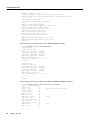
To load a Cisco IOS image on a line card, first use the copy tftp command to download the
Cisco IOS image to a slot on one of the PCMCIA Flash cards. After you have downloaded the
Cisco IOS image on the Flash card, perform the following tasks beginning in global configuration
mode:
Task
Command
Step 1
Specify the type of line card, location of
the Cisco IOS image, and the slot of the
line card to download the image. If the slot
number is omitted, the image is
downloaded to all line cards.
microcode {oc12-atm | oc12-pos | oc3-pos-4}
flash file_id slot-number
Step 2
Reload the image on the specified line
card.
microcode reload slot-number
Step 3
Exit configuration mode.
exit
Step 4
Connect to the line card and verify that the
new Cisco IOS image is on the line card
by checking the version number in the
display output.
execute-on slot slot-number show version
or
attach slot-number
show version
exit
Troubleshooting
The following sections provide some tools to troubleshoot problems on the Cisco 12000 series
routers. For more information, refer to the troubleshooting and diagnostic chapters in the Cisco
12000 series installation and configuration guides.
For a listing of system error messages, refer to the “System Error Messages” feature module.
Also refer to the “Monitoring and Maintaining the Cisco 12000 Series” section, later in this
document, for information on the show commands that might also be useful to troubleshoot
problems.
Using Field Diagnostics
Each line card on the Cisco 12000 series can perform field diagnostic testing to isolate faulty
hardware without disrupting normal operation of the system. However, performing field diagnostic
testing on a line card does halt all activity on the line card for the duration of the testing. After
successful completion of the field diagnostic testing, the Cisco IOS software is automatically
reloaded on the line card.
Note The field diagnostic diag command must be executed from the GRP main console port.
16
Release 11.2 GS
Storing Line Card Crash Information
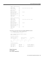
To perform field diagnostic testing on a line card, perform the following tasks in privileged EXEC
mode:
Task
Step 1
Command
Specify the line card that you want to
perform diagnostic testing on.
diag slot-number [previous | post | verbose | wait]
Optionally, specify that previous test
results are displayed, that only extended
power-on self-tests (POST) be performed,
that the maximum messages are displayed,
or that the Cisco IOS software not be
reloaded on the line card after successful
completion of the tests.
Step 2
At the prompt, press Return to confirm
that you want to perform field diagnostic
testing on the specified line card, or type
no to stop the testing.
Running Diags will halt ALL activity
on the requested slot. [confirm]
To stop field diagnostic testing on a line card, perform the following tasks in privileged EXEC mode:
Task
Command
Specify the line card that you want to stop perform
diagnostic testing on.
diag slot-number halt
or
no diag slot-number
Note When you stop the field diagnostic test, the line card remains down (that is, in an unbooted
state). In most cases, you stopped the testing because you need to remove the line card or replace the
line card. If that is not the case and you want to bring the line card back up (that is, on-line), you
must use the microcode reload global configuration command or power cycle the line card.
Storing Line Card Crash Information
This section explains how to enable storing of crash information for a line card and optionally
specify the type and amount of information stored. Technical support representatives need to be able
to look at the crash information from the line card to troubleshoot serious problems on the line card.
The crash information contains all the line card memory information including the main memory
and transmit and receive buffer information.
Caution Use the exception linecard global configuration command only when directed by a
technical support representative and only enable options that the technical support representative
requests you to enable.
Cisco 12000 Series Gigabit Switch Routers 17
Configuration Tasks
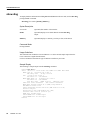
To enable and configure the crash information options for a line card, perform the following task in
global configuration mode:
Task
Command
Specify the line card that you want crash
information for when a line card resets. Optionally,
specify the type and amount of memory to be
stored.
exception linecard {all | slot number} [corefile
filename | main-memory size [k | m] | queue-ram
size [k | m] | rx-buffer size [k | m] |
sqe-register-rx | sqe-register-tx |
tx-buffer size [k | m]]
Monitoring and Maintaining the Cisco 12000 Series
The following sections describe some of the show commands you can use to obtain information
about the Cisco 12000 series, describe how to set the LED message on the line cards, and describe
the software components on the Cisco 12000 series and how to obtain information about these
components.
Displaying System Information Using Show Commands
To provide information about system processes, the Cisco IOS software includes an extensive list of
EXEC commands that begin with the word show, which, when executed, display detailed tables of
system information. Following is a list of some of the common show commands.
To use the show commands on a line card, you can use the execute-on privileged EXEC command
or you can connect to the Cisco IOS image running on the line card by using the attach privileged
EXEC command.
Refer to the “Command Reference” section for detailed command syntax for the new or modified
commands listed in this section.
Perform these tasks in privileged EXEC mode to display the information described:
18
Task
Command
Display information about the hardware.
show controllers
Display information stored in NVRAM when the
router crashes. This command is only useful to
technical support representatives.
show context
Display part number, revision number, and version
number information for the line cards.
show diag
Display the current environmental specifications.
show environment
Display hardware information.
show gsr
Display the state of syslog error and event logging.
show logging
Display memory pool statistics including summary
information about the activities of the system memory
allocator and a block-by-block listing of memory use.
show memory
Display the microcode bundled into the system image.
show microcode
Display information about all active processes.
show processes
Display the configured protocols.
show protocols
Release 11.2 GS
Setting the LED Message on the Line Cards
Task
Command
Display stack usage of processes and interrupt
routines, including the reason for the last system
reboot. This command is only useful to your technical
support representative.
show stacks
Display the status of TCP connections.
show tcp
Display a concise description of TCP connection
endpoints.
show tcp brief [all]
Display general information about the router when
reporting a problem.
show tech-support [page] [password]
Display configuration of the system hardware, the
software version, the names and sources of
configuration files, and the boot image.
show version
Setting the LED Message on the Line Cards
You can specify the message that is displayed on the LED on the front panel of one or more line
cards. You can also remove the user-specified message that is displayed on the LED on the front
panel of one or more line cards and revert to the normal status message for the line card.
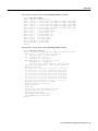
To set or clear the LED message, perform one of the following tasks in privileged EXEC mode:
Task
Command
Set the message displayed on the LED on the front
panel of one or more line cards.
set card-message {all | slot number} [expire
seconds] [blink seconds] message
Clear the user-specified message that is displayed
on the LED on the front panel of one or more line
cards and revert to the normal status message for
the line card.
clear card-message {all | slot number}
Understanding Software Components
There are many software components bundled with the Cisco IOS image for the Cisco 12000 series.
In most cases you do not need to know about these components; however, during troubleshooting,
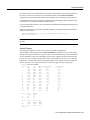
you might be asked for the specific version number of the various components. Table 1 describes
these software components, including those that are bundled with the Cisco IOS image for the
Cisco 12000 series and lists the command you would use to determine the version of the component.
Note The syntax for the show controller command listed in Table 1 is complex. For details on the
command syntax, refer to the “Command Reference” section.
Cisco 12000 Series Gigabit Switch Routers 19
Configuration Tasks
Table 1
Software
Component
Software Components in Cisco 12000 Series GSRs
Description
Version Information
MBus Agent Code
MBus agent code is bundled with the Cisco IOS
image on the GRP card. When the router is
powered on, the MBus agent powers on the GRP
card.
show diag1
GRP Cisco IOS
Image
Cisco IOS image that runs on the GRP card. This
is the main image for the Cisco 12000 series
GSR. It contains images for all the line card types
and various microcode bundles.
show version
GRP Boot Image
Cisco IOS image that runs on the GRP when it is
booting from the network. This image is
essentially the same as the Cisco IOS image, but it
has large portions of the routing software
removed because it only acts as an IP host to boot
the router. It has all the same line card images and
microcode bundles as the Cisco IOS image.
show version
Line Card Fabric
Downloader
Code that the MBus downloads to the line card so
the Cisco IOS image can be downloaded from the
GRP over the switch fabric. This is a bootstrap
loader that knows how to run the fabric only.
There is only one version of the downloader, and
it is bundled with the GRP Cisco IOS image.
show diag
Line Card
Cisco IOS Image
Cisco IOS image that runs on the line card. This
image is the main operational code for the line
card, and the image senses the type of line card it
is running on and adapts. It also supports all
variants of the line card. The line card Cisco IOS
image is bundled in the GRP Cisco IOS image.
execute-on slot slot-number show
version
or
attach slot-number
show version|
exit
SQE Microcode
Silicon queuing engine microcode on the line card
that controls the data paths on the line card. A
different microcode image might exist for each
type of line card and different microcode images
support different Cisco IOS features (for example,
weighted fair queueing). There is a default
microcode image that is used when no special
features or requirements exist. The SQE
microcode is bundled with the line card
Cisco IOS image.
execute-on slot slot-number show
controllers tofab bma microcode
execute-on slot slot-number show
controllers frfab bma microcode
or
attach slot-number
show controllers tofab bma microcode
show controllers frfab bma microcode
exit
ATM OC-12 SAR
Microcode
Microcode from the vendor of the SAR-622 chip
used on the ATM line card. The ATM SAR
microcode is bundled with the line card Cisco
IOS image.
execute-on slot slot-number show
controllers atm
or
attach slot-number
show controllers atm
exit
GRP Field
Diagnostic Image
20
Release 11.2 GS
Image that runs on the GRP when field
diagnostics are run with the diag command.
None
Understanding Software Components
Table 1
Software Components in Cisco 12000 Series GSRs (Continued)
Software
Component
Description
Version Information
Line Card Field
Diagnostic Image
Image that runs on the line card when field
diagnostics are run with the diag command.
None
GRP ROM Monitor
The ROM monitor is responsible for booting the
system from the local Flash devices. It is loaded
into the Flash ROM on the GRP when the board is
manufactured.
show version
Line Card ROM
Monitor
The ROM monitor is responsible for booting the
line card via the MBus. It is loaded into the Flash
ROM on the line card when the board is
manufactured.
execute-on slot slot-number show
version
or
attach slot-number
show version
exit
ROM Monitor
Library Image
Image that allows the GRP ROM monitor to
access the internal Flash bank and PCMCIA Flash
cards. It is bundled with the GRP Cisco IOS
image so it can be put on the Flash cards when
they are formatted. The GRP ROM monitor gets
the ROM monitor image from the Flash device
before accessing it.
None
1. You can also get version information from the first LED message.
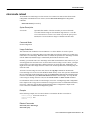
Configuration Example
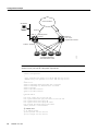
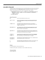
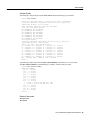
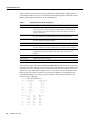
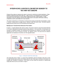
In a typical Internet service provider environment, the Cisco 12000 series routers reside within the
core of the network and can support as many as 44 OC-3/STM-1 IP over SONET/SDH optical links
to Cisco 7500 series routers or aggregation devices. Below is a typical configuration file for the
Cisco 12012. Important configuration commands are bolded. In this example, a Cisco 12000 series
router called GSR-A connects to the Internet backbone through interface POS11/0, connects to a
second Cisco 12000 series router through interface POS7/0, and connects to Cisco 7500 series
routers through interfaces POS4/0, POS4/1, POS4/2, and POS4/3. In addition, GSR-A also has a
connection to a workstation through interface E0 for TFTP functions only (no routing is performed).
Note In this example, SONET payload scrambling is enabled with the pos scramble-atm
command. SONET payload scrambling applies a self-synchronous scrambler (x^43+1) to the
Synchronous Payload Envelope (SPE) of the interface to ensure sufficient bit transition density. Both
sides of the connection must be configured using the pos scramble-atm command. Currently, when
connecting to a Cisco 7500 series router and using the pos scramble-atm command, you must
specify the crc 16 command rather than the crc 32 command.
Cisco 12000 Series Gigabit Switch Routers 21
Configuration Example
Internet backbone
Workstation
POS11/0
GSR – A
E0
622-Mbps POS
POS7/0
155-Mbps POS
Backbone
Cisco 12012
Gigabit Switch Routers
Aggregation/distribution
Cisco 7500 series routers
S6767
POS4/0 – POS4/3
Note Distributed Cisco Express Forwarding (CEF) is automatically enabled. Enable other CEF
features to meet your network configuration requirements.
Current configuration:
!
! Last configuration change at 15:41:46 PDT Tue Sep 30 1997
! NVRAM config last updated at 15:29:07 PDT Tue Sep 30 1997
!
version 11.2
service timestamps debug datetime msec localtime
service timestamps log datetime msec localtime
service internal
service udp-small-servers
service tcp-small-servers
!
hostname GSR-A
!
boot host config.dat 223.255.255.254
boot system banana/bfr/gsr-p-mz.fib20 223.255.255.254
boot system flash slot1:gsr-p-mz
boot system flash slot1:gsr-p-mz.fib19
boot bootldr bootflash:gsr-boot-mz.fib20
enable password 7 1222227220E09
!
ip subnet-zero
no ip domain-lookup
ip host peaches 223.255.254.254
ip host oranges 223.255.254.253
22
Release 11.2 GS
Understanding Software Components
! Enable CLNS routing on the router
clns routing
clock timezone PST -8
clock summer-time PDT recurring
clock calendar-valid
!
interface Loopback0
ip address 1.1.1.31 255.255.255.255
bandwidth 10000000
! Configure the Ethernet interface used for TFTP from the workstation
interface Ethernet0
ip address 16.4.237.10 255.255.0.0
ip broadcast-address 16.4.255.255
! Interfaces POS4/0 through POS4/3 are the OC3c connections
! to the Cisco 7500 series routers with scrambling
interface POS4/0
ip address 71.1.0.2 255.255.0.0
pos scramble-atm
crc 16
clock source internal
!
interface POS4/1
ip address 71.2.0.2 255.255.0.0
pos scramble-atm
crc 16
clock source internal
!
interface POS4/2
ip address 71.3.0.2 255.255.0.0
pos scramble-atm
crc 16
clock source internal
!
interface POS4/3
ip address 102.102.102.1 255.255.255.0
ip broadcast-address 102.102.102.255
pos scramble-atm
crc 16
clock source internal
! Interface POS7/0 is the OC12 connection
! to the second Cisco 12012 router
interface POS7/0
ip address 101.101.101.1 255.255.255.0
pos scramble-atm
crc 32
clock source internal
! Interface POS11/0 is the OC12 connection
! to the Internet
interface POS11/0
ip address 103.103.103.1 255.255.255.0
pos scramble-atm
crc 32
clock source internal
! Routing configured for the Ethernet interface (optional)
router eigrp 1009
passive-interface Ethernet0
network 107.0.0.0
network 108.0.0.0
!
router isis
redistribute connected metric 0 metric-type internal level-2
passive-interface Loopback0
net 47.0000.0031.0031.0000.0031.00
is-type level-2-only
! Routing configured for the Ethernet interface
Cisco 12000 Series Gigabit Switch Routers 23
Configuration Example
router igrp 199
network 16.0.0.0
!
router bgp 10
no synchronization
redistribute connected
redistribute static
neighbor 1.1.1.3 remote-as 10
neighbor 1.1.1.3 update-source Loopback0
neighbor 1.1.1.13 remote-as 10
neighbor 1.1.1.13 update-source Loopback0
neighbor 1.1.1.20 remote-as 10
neighbor 1.1.1.20 update-source Loopback0
no auto-summary
!
ip classless
ip default-network 33.0.0.0
ip route 33.0.0.0 255.0.0.0 33.34.0.0
ip route 223.255.0.0 255.255.0.0 Ethernet0
ip route 223.255.253.0 255.255.255.0 16.4.0.1
ip route 223.255.254.0 255.255.255.0 16.4.0.1
logging buffered 2000000 debugging
no logging console
tftp-server flash slot0:rsp-tpgenv-m.CZ.vjp alias rsp-tpgenv-m.CZ.vjp
!
snmp-server community public RO
snmp-server community passthru RW
snmp-server location HighEnd,Bldg.B,San Jose,CA
snmp-server contact Curt Applebee ([email protected])
!
line con 0
exec-timeout 0 0
password secret1
login
line aux 0
exec-timeout 0 0
transport input all
line vty 0 4
exec-timeout 0 0
password secret2
login
!
ntp clock-period 17179665
ntp update-calendar
no scheduler max-task-time
end
24
Release 11.2 GS
Understanding Software Components
Command Reference
This section documents new or modified commands. All other commands used with this feature are
documented in the Cisco IOS Release 11.2 command references.
Note The pos internal-clock interface configuration command has been replaced by the
clock source interface configuration command. The pos transmitter-delay interface configuration
command has been replaced by the transmitter-delay interface configuration command.
•
•
•
•
•
•
•
•
•
•
•
•
•
•
•
•
•
•
•
•
•
attach
atm sonet
clear card-message
clear logging
diag
exception linecard
execute-on
logging linecard
microcode (Cisco IOS image)
microcode reload
pos flag
pos framing
pos scramble-atm
set card-message
show context
show controllers (GRP image)
show controllers (line card image)
show diag
show environment
show gsr
show logging
Cisco 12000 Series Gigabit Switch Routers 25
Command Reference
attach
To access the Cisco IOS software image on a line card to monitor and maintain information on the
line card, use the attach privileged EXEC command. To exit from the Cisco IOS software image on
the line card and return to the Cisco IOS image on the GRP card, use the exit command.
attach slot-number
Syntax Description
slot-number
Slot number of the line card you want to connect to. Slot numbers
range from 0 to 11 for the Cisco 12012 and 0 to 7 for the Cisco 12008.
If the slot number is omitted, you are prompted for the slot number.
Default
Access to the Cisco IOS software image running on the GRP card.
Command Mode
Privileged EXEC
Usage Guidelines
This command was added in Cisco IOS Release 11.2 GS to support the Cisco 12000 series Gigabit
Switch Routers.
Use the attach EXEC command to get specific information about a line card.
After you connect to the Cisco IOS image on the line card using the attach command, the prompt
changes to “LC-Slotx#,” where x is the slot number of the line card.
You can also use the execute-on slot privileged EXEC command to execute commands on one or all
line cards.
Note Do not execute the config command from the Cisco IOS software image on the line card.
Note Because not all statistics are maintained on the line cards, the output from some of the show
commands might not be consistent.
26
Release 11.2 GS
attach
Example
The following example connects to the Cisco IOS image running on the line card in slot 9, gets a list
of valid show commands, and returns the Cisco IOS image running on the GRP:
Router# attach 9
Entering Console for 4 Port Packet Over SONET OC-3c/STM-1 in Slot: 9
Type exit to end this session
Press RETURN to get started!
LC-Slot9# show ?
cef
Cisco Express Forwarding
clock
Display the system clock
context
Show context information about recent crash(s)
history
Display the session command history
hosts
IP domain-name, lookup style, nameservers, and host table
ipc
Interprocess communications commands
location Display the system location
sessions Information about Telnet connections
terminal Display terminal configuration parameters
users
Display information about terminal lines
version
System hardware and software status
LC-Slot9# exit
Disconnecting from slot 9.
Connection Duration: 00:01:04
Router#
Related Commands
execute-on slot
Cisco 12000 Series Gigabit Switch Routers 27
Command Reference
atm sonet
To set the mode of operation and thus control type of the ATM cell used for cell-rate decoupling on
the SONET PLIM, use the atm sonet interface configuration command. To restore the default
Synchronous Transport Signal level 12, concatenated (STS-12c) operation, use the no form of this
command.
atm sonet [stm-4]
no atm sonet [stm-4]
Syntax Description
stm-4
(Optional) Synchronous Digital Hierarchy/Synchronous Transport
Signal level 4 (SDH/STM-4) operation (ITU-T specification).
Default
STS-12c
Command Mode
Interface configuration
Usage Guidelines
This command was modified in Cisco IOS Release 11.2 GS to add the stm-4 keyword.
Use STM-4 in applications where SDH framing is required.
Use the default (STS-12c) in applications where the ATM switch requires “unassigned cells” for rate
adaptation. An unassigned cell contains 32 zeros.
Example
The following example sets the mode of operation to SONET STM-4 on ATM interface 3/0:
Router(config)# interface atm 3/0
Router(config-if)# atm sonet stm-4
Router(config-if)# end
Router#
28
Release 11.2 GS
clear card-message
clear card-message
To remove the user-specified message that is displayed on the LED on the front panel of one or more
line cards and revert to the normal status message for the line card, use the clear card-message
privileged EXEC command.
clear card-message {all | slot slot-number}
Syntax Description
all
Clears the user-specified LED message on all line cards.
slot slot-number
Clears the user-specified LED message on a specific line card. Slot
numbers range from 0 to 11 for the Cisco 12012 and 0 to 7 for the
Cisco 12008.
Command Mode
Privileged EXEC
Usage Guidelines
This command was added in Cisco IOS Release 11.2 GS to support the Cisco 12000 series Gigabit
Switch Routers.
To specify the message that is displayed on the LED on the front panel of one or more line cards, use
the set card-message global configuration command.
Example
The following example clears any user-specified message from all line cards.
Router# clear card-message all
Router#
Related Commands
set card-message
Cisco 12000 Series Gigabit Switch Routers 29
Command Reference
clear logging
To clear messages from the logging buffer, use the clear logging privileged EXEC command.
clear logging {all | slot slot-number} [counts | messages]
Syntax Description
all
Clears the logging buffer for all slots.
slot slot-number
Clears the logging buffer for a specific slot. Slot numbers range from 0
to 11 for the Cisco 12012 and 0 to 7 for the Cisco 12008.
counts
(Optional) Clears the message counters only from the logging buffer.
The messages are kept.
messages
(Optional) Clears the messages from logging buffer (that is, discard all
messages in the log).
Default
If no options are specified, clear the counters and messages from the logging buffer for all line cards.
Command Mode
Privileged EXEC
Usage Guidelines
This command was modified in Cisco IOS Release 11.2 GS to include the all, slot, counts, and
messages keywords.
Use the show logging command to display logging information.
30
Release 11.2 GS
clear logging
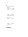
Example
In the following example, the counters and messages are cleared from the logging buffer on all line
cards. The show logging command shows the information before and after the log is cleared.
Router# show logging
Syslog logging: enabled (0 messages dropped, 0 flushes, 0 overruns)
Console logging: level debugging, 32 messages logged
Monitor logging: level debugging, 0 messages logged
Trap logging: level informational, 189 message lines logged
Buffer logging: level debugging, 32 messages logged
Log Buffer (1638 bytes):
2d17h: %SCHED-3-THRASHING: Process thrashing on watched managed timer (0x608610B0).
-Process= “User LED Message Process”, ipl= 6, pid= 14
-Traceback= 600CF7F0 600CFB18 60128900 600BFF88 600BFF74
2d17h: %SCHED-3-STUCKMTMR: Sleep w/expired mgd timer 6085F090, time 0xE151558 (0
0:00:07 ago).
-Process= “User LED Message Process”, ipl= 6, pid= 14
-Traceback= 600CF750 600CFB18 60128900 600BFF88 600BFF74
...
Router# clear logging
Clear logging buffer [confirm]
Router# show logging
Syslog logging: enabled (0 messages dropped, 0 flushes, 0 overruns)
Console logging: level debugging, 33 messages logged
Monitor logging: level debugging, 0 messages logged
Trap logging: level informational, 192 message lines logged
Buffer logging: level debugging, 33 messages logged
Log Buffer (1638 bytes):
Router#
Related Commands
logging buffered
logging linecard
show logging
Cisco 12000 Series Gigabit Switch Routers 31
Command Reference
diag
To perform field diagnostics on a line card, on the Gigabit Route Processor (GRP), on the Switch
Fabric Cards (SFC), and on the Clock Scheduler Card (CSC) in the Cisco 12000 series Gigabit
Switch Routers, use the diag privileged EXEC command. To disable field diagnostics on a line card,
use the no form of this command.
diag slot-number [halt | previous | post | verbose [wait] | wait]
no diag slot-number
Syntax Description
slot-number
Slot number of the line card you want to test. Slot numbers range from
0 to 11 for the Cisco 12012 and 0 to 7 for the Cisco 12008. Slot
numbers for the CSC are 16 and 17 and for the FSC are18, 19, and 20.
halt
(Optional) Stops the field diagnostic testing on the line card.
previous
(Optional) Displays previous test results (if any) for the line card.
post
(Optional) Initiates a EPROM-based extended power-on self-test
(EPOST) only. The EPOST test suite is not as comprehensive as the
field diagnostics, and a pass/fail message is the only message
displayed on the console.
verbose [wait]
(Optional) Enables the maximum status messages to be displayed on
the console. By default, only the minimum status messages are
displayed on the console. If you specify the optional wait keyword, the
Cisco IOS software is not be automatically reloaded on the line card
after the test completes successfully.
wait
(Optional) Stops the automatic reloading of the Cisco IOS software on
the line card after the successful completion of the field diagnostic
testing. If you use this keyword, you must use the microcode reload
slot global configuration command, or manually remove and insert the
line card (to power it up) in the slot so that the GRP will recognize the
line card and download the Cisco IOS software image to the line card.
Default
No field diagnostics tests are performed on the line card.
Command Mode
Privileged EXEC
Usage Guidelines
This command was added in Cisco IOS Release 11.2 GS to support the Cisco 12000 series Gigabit
Switch Routers.
Note The diag command must be executed from the GRP main console port.
32
Release 11.2 GS
diag
Perofrm diagnostics on the CSC only if a redendant CSC is in the router.
Diagnostics will stop and ask you for confirmation before altering the router’s configuration. For
example, running diagnostics on a SFC or CSC will cause the fabric to go from full bandwidth to
one quarter bandwidth. Bandwidth is not affected by GRP or line card diagnostics.
The field diagnostic software image is bundled with the Cisco IOS software and is downloaded
automatically from the GRP to the target line card prior to testing.
Caution Performing field diagnostics on a line card stops all activity on the line card. Before the
diag EXEC command begins running diagnostics, you are prompted to confirm the request to
perform field diagnostics on the line card.
In normal mode, if a test fails, the title of the failed test is displayed on the console. However, not all
tests that are preformed are displayed. To view all the tests that are performed, use the verbose
keyword.
After all diagnostic tests are completed on the line card, a PASSED or TEST FAILURE message is
displayed. If the line card sends a PASSED message, the Cisco IOS software image on the line card
is automatically reloaded unless the wait keyword is specified. If the line card sends a TEST
FAILURE message, the Cisco IOS software image on the line card is not automatically reloaded.
If you want to reload the line card after it fails diagnostic testing, use the microcode reload slot
global configuration command.
Note When you stop the field diagnostic test, the line card remains down (that is, in an unbooted
state). In most cases, you stopped the testing because you need to remove the line card or replace the
line card. If that is not the case, and you want to bring the line card back up (that is, online), you must
use the microcode reload global configuration command or power cycle the line card.
If the line card fails the test, the line card is defective and should be replaced. In future releases this
might not be the case because DRAM and SDRAM SIMM modules might be field replaceable units.
For example, if the DRAM test failed you might only need to replace the DRAM on the line card.
For more information, refer to the Cisco 12000 series installation and configuration guides.
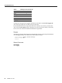
Examples
The following example shows the output when field diagnostics are performed on the line card in
slot 3. After the line card passes all field diagnostic tests, the Cisco IOS software is automatically
reloaded on the card. Before starting the diagnostic tests, you must confirm the request to perform
these tests on the line card because all activity on the line card is halted. The total/indiv. timeout set
to 600/220 sec. message indicates that 600 seconds are allowed to perform all field diagnostics tests,
and that no single test should exceed 220 seconds to complete.
Router# diag 3
Running Diags will halt ALL activity on the requested slot. [confirm]
Router#
Launching a Field Diagnostic for slot 3
Running DIAG config check
RUNNING DIAG download to slot 3 (timeout set to 400 sec.)
sending cmd FDIAG-DO ALL to fdiag in slot 3
(total/indiv. timeout set to 600/220 sec.)
Field Diagnostic ****PASSED**** for slot 3
Cisco 12000 Series Gigabit Switch Routers 33
Command Reference
Field Diag eeprom values: run 159 fial mode 0 (PASS) slot 3
last test failed was 0, error code 0
sending SHUTDOWN FDIAG_QUIT to fdiag in slot 3
Board will reload
...
Router#
The following example shows the output when field diagnostics are performed on the line card in
slot 3 in verbose mode.
Router# diag 3 verbose
Running Diags will halt ALL activity on the requested slot. [confirm]
Router#
Launching a Field Diagnostic for slot 3
Running DIAG config check
RUNNING DIAG download to slot 3 (timeout set to 400 sec.)
sending cmd FDIAG-DO ALL to fdiag in slot 3
(total/indiv. timeout set to 600/220 sec.)
FDIAG_STAT_IN_PROGRESS: test #1 R5K Internal Cache
FDIAG_STAT_PASS test_num 1
FDIAG_STAT_IN_PROGRESS: test #2 Sunblock Ordering
FDIAG_STAT_PASS test_num 2
FDIAG_STAT_IN_PROGRESS: test #3 Dram Datapins
FDIAG_STAT_PASS test_num 3
...
Field Diags: FDIAG_STAT_DONE
Field Diagnostic ****PASSED**** for slot 3
Field Diag eeprom values: run 159 fial mode 0 (PASS) slot 3
last test failed was 0, error code 0
sending SHUTDOWN FDIAG_QUIT to fdiag in slot 3
Board will reload
...
Router#
Related Commands
microcode reload
34
Release 11.2 GS
exception linecard
exception linecard
To enable storing of crash information for a line card and optionally specify the type and amount of
information stored, use the exception linecard global configuration command. To disable the
storing of crash information for the line card, use the no form of this command.
exception linecard {all | slot slot-number} [corefile filename | main-memory size [k | m] |
queue-ram size [k | m] | rx-buffer size [k | m] | sqe-register-rx | sqe-register-tx |
tx-buffer size [k | m]]
no exception linecard
Syntax Description
all
Stores crash information for all line cards.
slot slot- number
Stores crash information for the line card in the specified slot. Slot
numbers range from 0 to 11 for the Cisco 12012 and 0 to 7 for the
Cisco 12008.
corefile filename
(Optional) Stores the crash information in the specified file in
NVRAM. The default file name is hostname-core-slot-number (for
example, c12012-core-8).
main-memory size
(Optional) Stores the crash information for the main memory on the
line card and specify the size of the crash information. Size of the
memory to store is 0 to 268435456.
queue-ram size
(Optional) Stores the crash information for the queue RAM memory
on the line card and specify the size of the crash information. Size of
the memory to store can be from 0 to 1048576.
rx-buffer size
(Optional) Stores the crash information for the receive and transmit
buffer on the line card and specify the size of the crash information.
Size of the memory to store can be from 0 to 67108864.
tx-buffer size
sqe-register-rx
sqe-register-tx
k
m
(Optional) Stores crash information for the receive or transmit silicon
queueing engine registers on the line card.
(Optional) The k option multiplies the specified size by 1K (1024), and
the m option multiplies the specified size by 1M (1024*1024).
Default
No crash information is stored for the line card.
If enabled with no options, the default is to store 256 MB of main memory.
Command Mode
Global configuration
Cisco 12000 Series Gigabit Switch Routers 35
Command Reference
Usage Guidelines
This command was added in Cisco IOS Release 11.2 GS to support the Cisco 12000 series Gigabit
Switch Routers.
Use the exception linecard global configuration command only when directed by a technical
support representative and only enable options that the technical support representative requests you
to enable. Technical support representatives need to be able to look at the crash information from the
line card to troubleshoot serious problems on the line card. The crash information contains all the
line card memory information including the main memory and transmit and receive buffer
information.
Caution Use caution when enabling the exception linecard global configuration command.
Enabling all options could cause a large amount (150 to 250 MB) of crash information to be sent to
the server
Example
The following example enables the storing of crash information for line card 8. By default, 256 MB
of main memory is stored.
Router(config)# exception linecard slot 8
Router(config)# end
Router#
36
Release 11.2 GS
execute-on
execute-on
To execute commands remotely on a line card, use the execute-on slot privileged EXEC command.
execute-on {slot slot-number | all} command
Syntax Description
slot-number
Executes the command on the line card in the specified slot. Slot
numbers range from 0 to 11 on the Cisco 12012 and 0 to 7 on the
Cisco 12008.
all
Executes the command on all line cards.
command
Cisco IOS command to execute on the line card.
Command Mode
Privileged EXEC
Usage Guidelines
This command was added in Cisco IOS Release 11.2 GS to support the Cisco 12000 series Gigabit
Switch Routers.
Use this command to execute a command on one or all line cards to monitor and maintain
information on one or more line cards.
You can use the execute-on privileged EXEC command only from Cisco IOS software running on
the GRP card.
Note In Cisco IOS Release 11.2(9)GS, the execute-on command does not work properly on
commands that require input, the “more” autopaging mechanism does not function, and the line card
help is not available.
Note Because not all statistics are maintained on the line cards, the output from some of the show
commands might not be consistent.
You can also use the attach privileged EXEC command, but using the execute-on slot command
saves you some steps. For example, first you must use the attach command to connect you to the
Cisco IOS software running on the line card, next you must issue the command, and finally you must
disconnect from the line card to return to the Cisco IOS software running on the GRP card. With the
execute-on slot command, you can perform three steps with one command.
In addition, the execute-on all command allows you to perform the same command on all line cards.
Cisco 12000 Series Gigabit Switch Routers 37
Command Reference
Example
The following example shows how to execute the show controllers command on the line card in
slot 4:
Router# execute-on slot 4 show controllers
========= Line Card (Slot 4) =======
Interface POS0
Hardware is BFLC POS
lcpos_instance struct
6033A6E0
RX POS ASIC addr space 12000000
TX POS ASIC addr space 12000100
SUNI framer addr space 12000400
SUNI rsop intr status
00
CRC16 enabled, HDLC enc, int clock
no loop
Interface POS1
Hardware is BFLC POS
lcpos_instance struct
6033CEC0
RX POS ASIC addr space 12000000
TX POS ASIC addr space 12000100
SUNI framer addr space 12000600
SUNI rsop intr status
00
CRC32 enabled, HDLC enc, int clock
no loop
Interface POS2
Hardware is BFLC POS
lcpos_instance struct
6033F6A0
RX POS ASIC addr space 12000000
TX POS ASIC addr space 12000100
SUNI framer addr space 12000800
SUNI rsop intr status
00
CRC32 enabled, HDLC enc, int clock
no loop
Interface POS3
Hardware is BFLC POS
lcpos_instance struct
60341E80
RX POS ASIC addr space 12000000
TX POS ASIC addr space 12000100
SUNI framer addr space 12000A00
SUNI rsop intr status
00
CRC32 enabled, HDLC enc, ext clock
no loop
Router#
Related Commands
attach
38
Release 11.2 GS
logging linecard
logging linecard
To log messages to an internal buffer on a line card, use the logging linecard global configuration
command. To cancel the use of the internal buffer on the line cards, use the no form of this command.
logging linecard [size | message-level]
no logging linecard
Syntax Description
size
(Optional) Size of the buffer used for each line card. The range is 4096
to 65536 bytes. The default is 8 KB.
message-level
(Optional) Limits the logging of messages displayed on the console
terminal to a specified level. The message level can be:
• alerts—Immediate action needed
• critical—Critical conditions
• debugging—Debugging messages
• emergencies—System is unusable
• errors—Error conditions
• informational—Informational messages
• notifications—Normal but significant conditions
• warnings—Warning conditions
Default
The Cisco IOS software logs messages to the internal buffer on the GRP card.
Command Mode
Global configuration
Usage Guidelines
This command was added in Cisco IOS Release 11.2 GS to support the Cisco 12000 series Gigabit
Switch Routers.
Specifying a message level causes messages at that level and numerically lower levels to be stored
in the internal buffer on the line cards. Table 2 lists the message levels and associated numerical
level. For example, if you specify a message level of critical, all critical, alert, and emergency
messages will be logged.
Table 2
Message Levels
Level Name
Level
emergencies
0
alerts
1
critical
2
Cisco 12000 Series Gigabit Switch Routers 39
Command Reference
Table 2
Message Levels (Continued)
Level Name
Level
errors
3
warnings
4
notifications
5
informational
6
debugging
7
To display the messages that are logged in the buffer, use the EXEC command show logging slot.
The first message displayed is the oldest message in the buffer.
Do not make the buffer size too large because the router could run out of memory for other tasks.
You can use the show memory EXEC command to view the free processor memory on the router;
however, this is the maximum available and should not be approached.
Example
The following example enables logging to an internal buffer on the line cards using the default buffer
size and logging warning, error, critical, alert, and emergency messages:
Router(config)# logging linecard warnings
Router(config)# end
Router#
Related Commands
clear logging
show logging
40
Release 11.2 GS
microcode (Cisco IOS image)
microcode (Cisco IOS image)
To load a Cisco IOS software image on a line card from Flash memory or the GRP card on a
Cisco 12000 series Gigabit Switch Router, use the microcode global configuration command. To
load the microcode bundled with the GRP system image, use the no form of this command.
microcode interface {flash file-id [slot] | system [slot]}
no microcode interface [flash file-id [slot] | system [slot]]
Syntax Description
interface
One of the following interface names: oc12-atm, oc12-pos, or
oc3-pos-4.
flash
Loads the image from the Flash file system.
file-id
Specifies the device and filename of the image file to download. A
colon (:) must separate the device and filename (for example,
slot0:gsr-p-mz). Valid devices are as follows:
• bootflash—Internal Flash memory.
• slot0—First PCMCIA slot.
• slot1—Second PCMCIA slot.
slot
(Optional) Slot number of the line card that you want to copy the
software image to. Slot numbers range from 0 to 11 for the
Cisco 12012 and 0 to 7 for the Cisco 12008. If you do not specify a
slot number, the Cisco IOS software image is downloaded on all line
cards.
system
Loads the image from the software image on the GRP card.
Default
The default is to load the image from the GRP card.
Command Mode
Global configuration
Usage Guidelines
This command was modified in Cisco IOS Release 11.2 GS to load the Cisco IOS software image
onto a line card in the Cisco 12000 series Gigabit Switch Routers.
In addition to the Cisco IOS image that resides on the GRP card, each line card on a Cisco 12000
series has a Cisco IOS image. When the router is reloaded, the specified Cisco IOS image is loaded
onto the GRP card, and that image is automatically dowloaded to all the line cards.
Normally, you want the same Cisco IOS image on the GRP card and all line cards. However, if you
want to upgrade a line card with a new version of microcode for testing or to fix a defect, you might
need to load a Cisco IOS image that is different from the one on the line card. Additionally, you
might need to load a new image on the line card to work around a problem that is affecting only one
of the line cards.
Cisco 12000 Series Gigabit Switch Routers 41
Command Reference
To load a Cisco IOS image on a line card, first use the copy tftp command to download the
Cisco IOS image to a slot on one of the PCMCIA Flash memory cards. After you have downloaded
the Cisco IOS image on the Flash memory card, use the microcode command to download the image
to the line card followed by the microcode reload command to start the image. To verify that the
correct image is running on the line card, use the execute-on slot slot show version command.
For information on how to load Cisco IOS images, refer to the “Loading Images and Configuration
Files” chapter in the Configuration Fundamentals Configuration Guide. For additional information,
refer to the “Observing System Startup and Performing a Basic Configuration” chapter in the Cisco
12000 series installation and configuration guides.
Examples
In the following example, the Cisco IOS software image in slot 0: is downloaded to the line card in
slot 10. This is the software image that is used when the system is booted, when a line card is inserted
or removed, or when the microcode reload global configuration command is issued.
To verify that the correct version is loaded, use the execute-on slot 10 show version command.
Router(config)# microcode oc3-POS-4 flash slot0:fip.v141-7 10
Router(config)# microcode reload 10
Router(config)# exit
Router#
Related Commands
microcode reload
42
Release 11.2 GS
microcode reload
microcode reload
To reload the Cisco IOS image on a line card on Cisco 12000 series routers after all microcode
configuration commands have been entered, use the microcode reload global configuration
command.
microcode reload [slot-number]
Syntax Description
slot-number
(Optional) Slot number of the line card that you want to reload the
Cisco IOS software image on. Slot numbers range from 0 to 11 for the
Cisco 12012 and 0 to 7 for the Cisco 12008. If you do not specify a slot
number, the Cisco IOS software image is reloaded on all line cards.
Command Mode
Global configuration
Usage Guidelines
This command was modified in Cisco IOS Release 11.2 GS to add the slot-number option.
In addition to the Cisco IOS image that resides on the GRP card, each line card on Cisco 12000 series
routers has a Cisco IOS image. When the router is reloaded, the specified Cisco IOS image is loaded
onto the GRP card, and that image is automatically dowloaded to all the line cards.
Normally, you want the same Cisco IOS image on the GRP card and all line cards. However, if you
want to upgrade a line card with a new version of microcode for testing or to fix a defect, you might
need to load a Cisco IOS image that is different from the one on the line card. Additionally, you
might need to load a new image on the line card to work around a problem that is affecting only one
of the line cards.
To load a Cisco IOS image on a line card, first use the copy tftp command to download the
Cisco IOS image to a slot on one of the PCMCIA Flash memory cards. After you have downloaded
the Cisco IOS image on the Flash memory card, use the microcode command to download the image
to the line card followed by the microcode reload command to start the image. To verify that the
correct image is running on the line card, use the execute-on slot slot show version command.
For information on how to load Cisco IOS images, refer to the “Loading Images and Configuration
Files” chapter in the Configuration Fundamentals Configuration Guide. For additional information,
refer to the “Observing System Startup and Performing a Basic Configuration” chapter in the
Cisco 12000 series installation and configuration guides.
Example
In the following example, the Cisco IOS software is reloaded on the line card in slot 10:
Router(config)# microcode reload 10
Router(config)# end
Router#
Related Commands
microcode (Cisco IOS image)
microcode query
Cisco 12000 Series Gigabit Switch Routers 43
Command Reference
pos flag
To set the SONET overhead bytes in the frame header to meet a specific standards requirement or to
ensure interoperability with another vendor’s equipment, use the pos flag interface configuration
command. To remove the setting of the SONET overhead bytes, use the no form of this command.
pos flag {c2 | j0 | s1s0} value
no pos flag {c2 | j0 | s1s0} value
Syntax Description
c2 value
Path signal identifier used to identify the payload content type. Use the
following values to tell the SONET transmission equipment the payload
type:
• For PPP (or HDLC when required), use 0xCF (this is the default).
• For ATM, use 0x13.
• For other equipment, use any non-zero value.
The byte value can be 0 to 255.
j0 value
Section trace byte (formerly the C1 byte). For interoperability with SDH
equipment in Japan, use the value 0x1. The byte value can be 0 to 255.
sls0 value
S1 and S0 bits (bits 5 and 6 of the H1 #1 payload pointer byte). Use the
following values to tell the SONET transmission equipment the SS bit:
• For OC-3c, use 0 (this is the default).
• For AU-4 container in SDH, use 2.
The S1 and S0 bits can be 0 to 3. Values 1 and 3 are undefined.
Default
The default c2 value is 0xCF, and the default sls0 value is 0.
Command Mode
Interface configuration
Usage Guidelines
This command was added in Cisco IOS Release 11.2 GS to support the Cisco 12000 series Gigabit
Switch Routers.
Example
The following example sets the path signal identifier used to identify the payload content type to
ATM on the line card in slot 9:
Router(config)# interface pos 9/0
Router(config-if)# pos flag c2 0x13
Router(config-if)# end
Router#
44
Release 11.2 GS
pos framing
pos framing
To specify the framing used on the POS interface, use the pos framing interface configuration
command. To return to the default SONET STS-3c framing mode, use the no form of this command.
pos framing {sdh | sonet}
no pos framing
Syntax Description
sdh
Selects SDH STM-1 framing. This framing mode is typically used in
Europe.
sonet
Selects SONET STS-3c framing. This is the default.
Default
SONET STS-3c framing
Command Mode
Interface configuration
Usage Guidelines
This command was modified in Cisco IOS Release 11.2 GS to change the command syntax from
pos framing-sdh to pos framing and add the sonet keyword.
Example
In the following example, the interface is configured for SDH STM-1 framing:
Router(config)# interface pos 3/0
Router(config-if)# pos framing sdh
Router(config-if)# no shutdown
Router(config-if)# end
Router#
Related Commands
interface pos
Cisco 12000 Series Gigabit Switch Routers 45
Command Reference
pos scramble-atm
To enable SONET payload scrambling on a POS interface, use the pos scramble-atm interface
command. To disable scrambling, use the no form of this command.
pos scramble-atm
no pos scramble-atm
Syntax Description
This command has no keywords or arguments.
Default
Disabled.
Command Mode
Interface configuration
Usage Guidelines
This command was added in Cisco IOS Release 11.2 GS to support the Cisco 12000 series Gigabit
Switch Routers.
SONET payload scrambling applies a self-synchronous scrambler (x^43+1) to the Synchronous
Payload Envelope (SPE) of the interface to ensure sufficient bit transition density.
Both ends of the connection must use the same scrambling algorithm.
When enabling POS scrambling on a VIP2 POSIP on the Cisco 7500 series that has a hardware
revision of 1.5 or higher, you can specify CRC 16 only (that is, CRC 32 is currently not supported).
To determine the hardware version of the POSIP, use the show diag command. The POS interface
on the Cisco 12000 series has no restrictions.
To determine whether scrambling is enabled on the interface, use the show interface pos command
or show startup-config command.
Example
The following example enables scrambling on the interface:
Router(config)# interface pos 3/0
Router(config-if)# pos scramble-atm
Router(config-if)# no shutdown
Router(config-if)# end
Router#
Related Commands
interface pos
show interface pos
46
Release 11.2 GS
set card-message
set card-message
To specify the message that is displayed on the LED on the front panel of one or more line cards, use
the set card-message privileged EXEC command. To remove the message, use the clear
card-message global command.
set card-message {all | slot slot-number} [expire seconds] [blink seconds] message
Syntax Description
all
Specifies that the LED message is set on all line cards.
slot slot-number
Specifies that the LED message is set on a specific line card. Slot numbers
range from 0 to 11 for the Cisco 12012 and 0 to 7 for the Cisco 12008.
expire seconds
(Optional) Specifies how long the message is displayed on the front panel
LED. The range is 0 to 31536000 seconds. When you select 0, the message
remains on the LED until you clear it by using the clear card-message
command. When the time expires, the user-specified message is removed,
and the LED displays the status message based on the line card’s last state.
blink seconds
(Optional) Specifies how often the message blinks (that is, goes on and off)
in seconds. The range is 1 to 10 seconds. If blink is not specified, the
message does not blink.
message
Specifies the text to display on the LED on the front panel of one or more
line cards. The message can be up to eight alphanumeric characters (four
characters per line).
Default
System LED message is displayed.
Command Mode
Privileged EXEC
Usage Guidelines
This command was added in Cisco IOS Release 11.2 GS to support the Cisco 12000 series Gigabit
Switch Routers.
The user-specified message is also displayed in the show diag command output.
To revert to the normal status message for the line card, use the clear card-message global
configuration command.
Example
The following example sets the message USER MSG to display on the LED on line card 3. This
message blinks every two seconds.
Router# set card-message slot 3 blink 2 USER MSG
Related Commands
clear card-message
show diag
Cisco 12000 Series Gigabit Switch Routers 47
Command Reference
show context
To display information stored in NVRAM when the router crashes, use the show context EXEC
command.
show context summary
show context {all | slot slot-number [crash-index] [all] [debug]}
Syntax Description
summary
Displays a summary of all the crashes recorded.
all
Displays all crashes for all the slots. When optionally used with the slot
keyword, displays crash information for the specified slot.
slot slot-number
[crash-index]
Displays information for a particular line card. Slot numbers range from 0
to 11 for the Cisco 12012 and 0 to 7 for the Cisco 12008. Index number
allows you to look at previous crash contexts. Contexts from the last 24
line card crashes are saved on the GRP card. If the GRP reloads, the last 24
line card crash contexts are lost. For example, show context slot 3 2 shows
the second most recent crash for line card in slot 3. Index numbers are
displayed by the show context summary command
debug
(Optional) Displays crash information as hex record dump in addition to
one of the options listed above.
Command Mode
EXEC
Usage Guidelines
This command was modified in Cisco IOS Release 11.2 GS to add the all, debug, slot, and
summary keywords.
The display from the show context command includes the following information:
•
•
•
•
•
Reason for the system reboot
Stack trace
Software version
The signal number, code, and router uptime information
All the register contents at the time of the crash
Note This information is of use only to technical support representatives in analyzing crashes in the
field. It is included here in case you need to read the displayed statistics to an engineer over the
phone.
48
Release 11.2 GS
show context
Sample Display
The following is sample output from the show context command following a system failure:
Router> show context
System was restarted by error - a Software forced crash, PC 0x60189354
GS Software (RSP-PV-M), Experimental Version 11.1(2033) [ganesh 111]
Compiled Mon 31-Mar-97 13:21 by ganesh
Image text-base: 0x60010900, data-base: 0x6073E000
Stack trace from system failure:
FP: 0x60AEA798, RA: 0x60189354
FP: 0x60AEA798, RA: 0x601853CC
FP: 0x60AEA7C0, RA: 0x6015E98C
FP: 0x60AEA7F8, RA: 0x6011AB3C
FP: 0x60AEA828, RA: 0x601706CC
FP: 0x60AEA878, RA: 0x60116340
FP: 0x60AEA890, RA: 0x6011632C
Fault History Buffer:
GS Software (RSP-PV-M), Experimental Version 11.1(2033) [ganesh 111]
Compiled Mon 31-Mar-97 13:21 by ganesh
Signal = 23, Code = 0x24, Uptime 00:04:19
$0 : 00000000, AT : 60930120, v0 : 00000032, v1 : 00000120
a0 : 60170110, a1 : 6097F22C, a2 : 00000000, a3 : 00000000
t0 : 60AE02A0, t1 : 8000FD80, t2 : 34008F00, t3 : FFFF00FF
t4 : 00000083, t5 : 3E840024, t6 : 00000000, t7 : 11010132
s0 : 00000006, s1 : 607A25F8, s2 : 00000001, s3 : 00000000
s4 : 00000000, s5 : 00000000, s6 : 00000000, s7 : 6097F755
t8 : 600FABBC, t9 : 00000000, k0 : 30408401, k1 : 30410000
gp : 608B9860, sp : 60AEA798, s8 : 00000000, ra : 601853CC
EPC : 60189354, SREG : 3400EF03, Cause : 00000024
Router>
The following is sample output from the show context summary command on a Cisco 12012 router.
The show context summary command displays a summary of all the crashes recorded.
Router# show context summary
CRASH INFO SUMMARY
Slot 0 : 0 crashes
Slot 1 : 0 crashes
Slot 2 : 0 crashes
Slot 3 : 0 crashes
Slot 4 : 0 crashes
Slot 5 : 0 crashes
Slot 6 : 0 crashes
Slot 7 : 2 crashes
1 - crash at 18:06:41 UTC Tue Nov 5 1996
2 - crash at 12:14:55 UTC Mon Nov 4 1996
Slot 8 : 0 crashes
Slot 9 : 0 crashes
Slot 10: 0 crashes
Slot 11: 0 crashes
Router#
Related Commands
show processes
show stacks
Cisco 12000 Series Gigabit Switch Routers 49
Command Reference
show controllers (GRP image)
To display information that is specific to the hardware, use the show controllers privileged EXEC
command.
show controllers [atm number | clock | csar [register] | csc-fpga | dp83800 | fab-clk |
fia [register] | pos [number] [details] | queues [slot-number] | sca | xbar]
Syntax Description
50
atm number
(Optional) Displays the ATM controllers. Number is
slot-number/ port-number (for example, 4/0). Slot numbers
range from 0 to 11 for the Cisco 12012 and 0 to 7 for the Cisco
12008.
clock
(Optional) Displays the clock card configuration.
csar [register]
(Optional) Displays the Cisco Cell Segmentation and
Reassembly (CSAR) information. CSAR is the name of the
chip on the card that handles traffic between the GRP and the
switch fabric interface ASICs.
csc-fpga
(Optional) Displays the clock and scheduler card register
information in the field programmable gate array (FPGA).
dp83800
(Optional) Displays the Ethernet information on the GRP card.
fab-clk
(Optional) Display the switch fabric clock register information.
The switch fabric clock FPGA is a chip that monitors the
incoming fabric clock generated by the switch fabric. This clock
is needed by each card connecting to the switch fabric to
properly communicate with it. There are two switch fabric
clocks arriving at each card; only one can be used. The FPGA
monitors both clocks and selects which one to use if only one of
them is running.
fia [register]
(Optional) Displays the fabric interface ASIC information and
optionally display the register information.
pos [number] [details]
(Optional) Displays the POS framer state and optionally
displays all the details for the interface. Number is slot-number/
port-number (for example, 4/0). Slot numbers range from 0 to
11 for the Cisco 12012 and 0 to 7 for the Cisco 12008.
queues [slot-number]
(Optional) Displays the SDRAM buffer carve information and
optionally displays the information for a specific line card. The
SDRAM buffer carve information displayed is suggested carve
information from the GRP card to the line card. Line cards
might change the shown percentages based on SDRAM
available. Slot numbers range from 0 to 11 for the Cisco 12012
and 0 to 7 for the Cisco 12008.
sca
(Optional) Displays the SCA register information. The SCA is
an ASIC that arbitrates among the line cards requests to use the
switch fabric.
Release 11.2 GS
show controllers (GRP image)
xbar
(Optional) Displays the crossbar register information. The
XBAR is an ASIC that switches the data as it passes through the
switch fabric.
Command Mode
Privileged EXEC
Usage Guidelines
This command was added in Cisco IOS Release 11.2 GS to support the Cisco 12000 series Gigabit
Switch Routers.
Note This information is of use only to technical support representatives in analyzing system
failures in the field. It is included here in case you need to read the displayed statistics to an engineer
over the phone.
Sample Display
The following example is sample output from the show controllers pos command for a
Cisco 12012.
Router# show controllers pos 7/0
POS7/0
SECTION
LOF = 2
LOS = 0
Active Alarms: None
LINE
AIS = 2
RDI = 2
FEBE = 146
Active Alarms: None
PATH
AIS = 2
RDI = 4
FEBE = 63
LOP = 0
PSE = 8
NSE = 3
Active Alarms: None
APS
COAPS = 3
PSBF = 2
State: PSBF_state = False
Rx(K1/K2): F0/15 Tx(K1/K2): 00/00
S1S0 = 00, C2 = 64
PATH TRACE BUFFER : STABLE
Remote hostname : GSR-C
Remote interface: POS10/0
Remote IP addr : 10.201.101.2
Remote Rx(K1/K2): F0/15 Tx(K1/K2): 00/00
Router#
BIP(B1) = 5889
BIP(B2) = 2106453
BIP(B3) = 3216
NEWPTR = 2
Related Commands
clear controllers
show controllers (line card image)
Cisco 12000 Series Gigabit Switch Routers 51
Command Reference
show controllers (line card image)
To display information that is specific to the hardware on a line card, use the attach privileged EXEC
command to connect to the line card and then use the show controllers privileged EXEC command
or the execute-on privileged EXEC command.
show controllers atm [[port-number] [all | sar | summary]]
show controllers fia [register]
show controllers {frfab | tofab} {bma {microcode | ms-inst | register} |
qelem start-queue-element [end-queue-element] |
qnum start-queue-number [end-queue-number] |
queues | statistics}
show controllers io
show controllers l3
show controllers pos {framers | queues | registers |
rxsram port-number queue-start-address [queue-length] |
txsram port-number queue-start-address [queue-length]}
Syntax Description
atm [[port-number] [all | sar |
summary]]
Displays the ATM controller information. Optionally
displays ATM controllers for a specific line card and lists
all details, lists SAR interactive command, or lists SAR
status summary.
fia [register]
Displays the fabric interface ASIC information and
optionally displays the register information.
{frfab | tofab}
Displays the from fabric (transmit) or to fabric (receive)
information.
bma {microcode | ms-inst | register} For the frfab or tofab keywords, displays silicon queueing
engine (SQE) information for the microcode bundled in the
line card and currently running version, the micro
sequencer instructions, or the registers. The silicon
queueing engine is the same as the BMA.
52
qelem start-queue [end-queue]
For the frfab or tofab keywords, displays the SDRAM
buffer pool queue element summary information by
specifying the start queue element number (0 to 65535) and
optionally the end queue element number (0 to 65535).
qnum start-queue [end-queue]
For the frfab or tofab keywords, displays the SDRAM
buffer pool queue detail information by specifying the start
free queue number (0 to 127) and optionally the end free
queue number (0 to 127).
queues
For the frfab or tofab keywords, displays the SDRAM
buffer pool information.
statistics
For the frfab or tofab keywords, displays the BMA
counters.
io
Displays input/output registers.
Release 11.2 GS
show controllers (line card image)
l3
Displays Layer 3 ASIC information.
pos {framers | queues | registers |
rxsram port-number
queue-start-address [queue-length] |
txsram port-number
queue-start-address [queue-length]}
Displays the POS framer registers, queue information,
ASIC registers, receive queue SRAM, or transmit queue
SRAM information. When you display the transmit or
receive queue information, you must specify a port (valid
range is 0 to 3) and the queue SRAM logical starting
address. You can also optionally specify the queue SRAM
length.
Command Mode
Privileged EXEC
Usage Guidelines
This command was added in Cisco IOS Release 11.2 GS to support the Cisco 12000 series Gigabit
Switch Routers.
Note This information is of use only to technical support representatives in analyzing crashes in the
field. It is included here in case you need to read the displayed statistics to an engineer over the
phone.
Sample Displays
Because you are executing this command on the line card, you must use the execute-on command
to perform the show command, or you must connect to the card using the attach command. All
examples in this section use the execute-on command
The following is partial sample output from the show controllers atm command.
Router# execute-on slot 4 show controllers atm 0
TX SAR (Beta 1.0.0) is Operational;
RX SAR (Beta 1.0.0) is Operational;
Interface Configuration Mode:
STS-12c
Active Maker Channels: total # 6
VCID ChnnlID Type OutputInfo
1
0888
UBR
0C010010
2
0988
VBR
04010020
3
8BC8
UBR
0C010030
4
0E08
UBR
0C010040
10
1288
VBR
040100A0
11
8BE8
VBR
0C0100B0
InPkts
0
0
0
0
0
0
InOAMs
0
0
0
0
0
0
MacString
08882000AAAA030000000800
09882000
8BC82000AAAA030000000800
0E082000AAAA030000000800
12882000
8BE82000AAAA030000000800
SAR Total Counters:
total_tx_idle_cells 215267 total_tx_paks 0 total_tx_abort_paks 0
total_rx_paks 0 total_rx_drop_paks 0 total_rx_discard_cells 15
Switching Code Counters:
total_rx_crc_err_paks 0 total_rx_giant_paks 0
total_rx_abort_paks 0 total_rx_crc10_cells 0
total_rx_tmout_paks 0 total_rx_unknown_paks 0
total_rx_out_buf_paks 0 total_rx_unknown_vc_paks 0
Cisco 12000 Series Gigabit Switch Routers 53
Command Reference
BATMAN Asic Register Values:
hi_addr_reg 0x8000, lo_addr_reg 0x000C, boot_msk_addr 0x0780,
rmcell_msk_addr 0x0724, rmcnt__msk_addr 0x07C2, txbuf_msk_addr 0x070C,
...
CM622 SAR Boot Configuration:
txind_q_addr 0x14000 txcmd_q_addr 0x20000
...
SUNI-622 Framer Register Values:
Master Rst and Ident/Load Meters Reg (#0x0): 0x10
Master Configuration Reg (#0x1): 0x1F
Master Interrupt Status Reg (#0x2): 0x00
PISO Interrupt Reg (#0x3): 0x04
Master Auto Alarm Reg (#0x4): 0x03
Master Auto Alarm Reg (#0x5): 0x07
Parallel Output Port Reg (#0x6): 0x02
...
BERM Line BIP Threshold LSB Reg (#0x74): 0x00
BERM Line BIP Threshold MSB Reg (#0x75): 0x00
Router#
The following is partial sample output from the show controllers command.
Router# execute-on slot 6 show controllers
Interface POS0
Hardware is BFLC POS
lcpos_instance struct
60311B40
RX POS ASIC addr space 12000000
TX POS ASIC addr space 12000100
SUNI framer addr space 12000400
SUNI rsop intr status
00
CRC32 enabled, HDLC enc, int clock
no loop
Interface POS1
Hardware is BFLC POS
lcpos_instance struct
603142E0
RX POS ASIC addr space 12000000
TX POS ASIC addr space 12000100
SUNI framer addr space 12000600
SUNI rsop intr status
00
CRC32 enabled, HDLC enc, int clock
no loop
...
Router#
The following is partial sample output from the show controllers pos framers command.
Router# execute-on slot 6 show controllers pos framers
Framer 0, addr=0x12000400:
master reset
C0
master config
1F
rrate sts3c trate sts3c fixptr
master control
00
clock rcv cntrl
D0
RACP control
84
RACP gfc control
0F
TACP control status
04
hcsadd
RACP intr enable
04
RSOP cntrl intr enable 00
RSOP intr status
00
TPOP path sig lbl (c2) 13
SPTB control
04
tnull
SPTB status
00
54
Release 11.2 GS
show controllers (line card image)
Framer 1, addr=0x12000600:
master reset
C0
master config
1F
master control
00
clock rcv cntrl
D0
RACP control
84
RACP gfc control
0F
TACP control status
04
RACP intr enable
04
RSOP cntrl intr enable 00
RSOP intr status
00
TPOP path sig lbl (c2) 13
SPTB control
04
SPTB status
00
Framer 2, addr=0x12000800:
master reset
C0
master config
1F
master control
00
clock rcv cntrl
D0
RACP control
84
RACP gfc control
0F
TACP control status
04
RACP intr enable
04
RSOP cntrl intr enable 00
RSOP intr status
00
TPOP path sig lbl (c2) 13
SPTB control
04
SPTB status
00
...
Router#
rrate sts3c trate sts3c fixptr
hcsadd
tnull
rrate sts3c trate sts3c fixptr
hcsadd
tnull
The following is partial sample output from the show controllers fia command.
Router# execute-on slot 7 show controllers fia
========= Line Card (Slot 7) =======
Fabric configuration: Full bandwidth redundant
Master Scheduler: Slot 17
From Fabric FIA Errors
----------------------redund fifo parity 0
crc32 lkup parity 0
0
1
--------------los
0
0
crc16 0
0
To Fabric FIA Errors
----------------------sca not pres 0
grant parity 0
cntrl parity 0
multi fifo
0
redund overflow 0
cell parity
0
2
3
--------------0
0
0
0
req error
multi req
uni req
empty dst req
0
0
0
0
cell drops 0
crc32
0
4
-------0
0
uni fifo overflow
uni fifo undrflow
crc32 lkup parity
handshake error
0
0
0
0
Related Commands
clear controllers
show controllers (GRP image)
Cisco 12000 Series Gigabit Switch Routers 55
Command Reference
show diag
To display hardware information including DRAM and SRAM on the line cards, use the show diag
privileged EXEC command.
show diag [slot-number] [details] [summary]
Syntax Description
slot-number
(Optional) Slot number of the interface.
details
(Optional) Displays more details than the normal show diag
output.
summary
(Optional) Displays a summary (one line per slot) of the chassis.
Command Mode
Privileged EXEC
Usage Guidelines
This command was modified in Cisco IOS Release 11.2 GS to include sample output from the
Cisco 12000 series Gigabit Switch Routers.
Use this command to determine the type of hardware installed in your router.
Sample Display
The following is sample output from the show diag command:
Router# show diag 3
SLOT 3 (RP/LC 3 ): 4 Port Packet Over SONET OC-3c/STM-1 Multi Mode
MAIN: type 33, 00-0000-00 rev 70 dev 0
HW config: 0x01
SW key: 00-00-00
PCA: 73-2147-02 rev 94 ver 2
HW version 1.0 S/N 04499695
MBUS: MBUS Agent (1) 73-2146-05 rev 73 dev 0
HW version 1.1 S/N 04494882
Test hist: 0x00
RMA#: 00-00-00
RMA hist: 0x00
DIAG: Test count: 0x05000001
Test results: 0x00000000
MBUS Agent Software version 01.27 (RAM) using CAN Bus A
ROM Monitor version 00.0D
Fabric Downloader version used 00.0D (ROM version is 00.0D)
Board is analyzed
Board State is Line Card Enabled (IOS RUN )
Insertion time: 00:00:10 (00:04:51 ago)
DRAM size: 33554432 bytes
FrFab SDRAM size: 67108864 bytes
ToFab SDRAM size: 16777216 bytes
Router#
56
Release 11.2 GS
show diag
The following is sample output from the show diag summary command:
Router#
SLOT 0
SLOT 2
SLOT 4
SLOT 7
SLOT 9
SLOT 11
SLOT 16
SLOT 17
SLOT 18
SLOT 19
SLOT 20
SLOT 24
SLOT 26
SLOT 28
SLOT 29
Router#
show diag summary
(RP/LC 0 ): Route Processor
(RP/LC 2 ): 4 Port Packet Over SONET
(RP/LC 4 ): 4 Port Packet Over SONET
(RP/LC 7 ): 4 Port Packet Over SONET
(RP/LC 9 ): 4 Port Packet Over SONET
(RP/LC 11): 4 Port Packet Over SONET
(CSC 0
): Clock Scheduler Card
(CSC 1
): Clock Scheduler Card
(SFC 0
): Switch Fabric Card
(SFC 1
): Switch Fabric Card
(SFC 2
): Switch Fabric Card
(PS A1
): AC Power Supply
(PS B1
): AC Power Supply
(TOP FAN ): Blower Module
(BOT FAN ): Blower Module
OC-3c/STM-1
OC-3c/STM-1
OC-3c/STM-1
OC-3c/STM-1
OC-3c/STM-1
Single
Single
Single
Single
Single
Mode
Mode
Mode
Mode
Mode
The following is sample output from the show diag details command:
Router# show diag 4 details
SLOT 4 (RP/LC 4): 4 Port Packet Over SONET OC-3c/STM-1 Single Mode
MAIN: type 33, 800-2389-01 rev 71 dev 16777215
HW config: 0x00
SW key: FF-FF-FF
PCA: 73-2275-03 rev 75 ver 3
HW version 1.1 S/N 04529465
MBUS: MBUS Agent (1) 73-2146-06 rev 73 dev 0
HW version 1.1 S/N 04541395
Test hist: 0xFF
RMA#: FF-FF-FF
RMA hist: 0xFF
DIAG: Test count: 0x05000001
Test results: 0x00000000
EEPROM contents (hex):
00: 01 00 01 00 49 00 08 62 06 03 00 00 00 FF FF FF
10: 30 34 35 34 31 33 39 35 FF FF FF FF FF FF FF FF
20: 01 01 00 00 00 00 00 FF FF FF FF FF FF FF FF FF
30: A5 FF A5 A5 A5 A5 FF A5 A5 A5 A5 A5 A5 A5 A5 A5
40: 00 21 01 01 00 49 00 08 E3 03 05 03 00 01 FF FF
50: 03 20 00 09 55 01 01 FF FF FF 00 FF FF FF FF FF
60: 30 34 35 32 39 34 36 35 FF FF FF FF FF FF FF FF
70: FF FF FF FF FF FF FF FF 05 00 00 01 00 00 00 00
MBUS Agent Software version 01.24 (RAM)
Fabric Downloader version 00.0D
Board is analyzed
Flags: 0x4
Board State is Line Card Enabled (IOS RUN)
Insertion time: 00:00:10 (00:04:51 ago)
DRAM size: 33554432 bytes
FrFab SDRAM size: 67108864 bytes
ToFab SDRAM size: 16777216 bytes
Router#
Cisco 12000 Series Gigabit Switch Routers 57
Command Reference
show environment
To display temperature, voltage, and blower information on the Cisco 12000 series Gigabit Switch
Router, use the show environment privileged EXEC command.
show environment [alarms | all | fans | hardware | last | leds | power-supply | table |
temperatures | voltages]
Syntax Description
alarms
(Optional) Displays the alarm contact information.
all
(Optional) Displays a detailed listing of the power supplies,
temperature readings, voltage readings, and blower speeds.
fans
(Optional) Displays blower and fan information.
hardware
(Optional) Displays hardware-specific information.
last
(Optional) Displays information on the last measurement made.
leds
(Optional) Displays the status of the MBus LEDs on the clock and
scheduler cards and switch fabric cards.
power-supply
(Optional) Displays power supply voltage and current information.
table
(Optional) Displays the temperature, voltage, and blower thresholds.
temperature
(Optional) Displays temperature information.
voltages
(Optional) Displays voltage information.
Default
If no options are specified, the current environmental parameters are displayed.
Command Mode
Privileged EXEC
Usage Guidelines
This command was modified in Cisco IOS Release 11.2 GS to include the alarms, fans, hardware,
leds, power-supply, temperature, and voltages keywords and to provide sample output for the
Cisco 12000 series Gigabit Switch Routers.
Once a minute a routine is run that gets environmental measurements from sensors and stores the
output into a buffer. This buffer is displayed on the console when show environment is invoked.
If a measurement exceeds desired margins, but has not exceeded fatal margins, a warning message
is printed to the system console. The system software queries the sensors for measurements once a
minute, but warnings for a given test point are printed at most once every hour for sensor readings
in the warning range and once every 5 minutes for sensor readings in the critical range. If a
58
Release 11.2 GS
show environment
measurement is out of line within these time segments, an automatic warning message appears on
the console. As noted, you can query the environmental status with the show environment
command at any time to determine whether a measurement is at the warning or critical tolerance.
If a shutdown occurs because of detection of fatal environmental margins, the last measured value
from each sensor is stored in internal nonvolatile memory.
For environmental specifications, refer to the hardware installation and configuration publication for
your individual chassis.
If the Cisco 12000 series exceeds environmental conditions, a message similar to the one below is
displayed on the console:
%GSR_ENV-2-WARNING: Slot 3 Hot Sensor Temperature exceeds 40 deg C;
Check cooling systems
Note Blower temperatures that exceed environmental conditions do not generate a warning
message.
Sample Displays
The following examples are for the Cisco 12000 series Gigabit Switch Routers.
The following is sample output from the show environment command for a Cisco 12012. Slots 0
through 11 are the line cards, slots 16 and 17 are the clock and scheduler cards, slots 18 through 20
are the switch fabric cards, slots 24 through 27 are the power supplies, and slots 28 and 29 are the
blowers. An “NA” in the table means that no values was returned. In some cases it is because the
equipment is not supported for that environmental parameter (for example, the power supply and
blowers in slots 24, 26, 28, and 29 do not have a 3V power supply so an NA is displayed).
Router# show environment
Slot # 3V
5V
MBUS 5V Hot Sensor
(mv)
(mv)
(mv)
(deg C)
0
3300
4992
5040
42.0
2
3296
4976
5136
40.0
4
3280
4992
5120
38.5
7
3280
4984
5136
42.0
9
3292
4968
5160
39.5
11
3288
4992
5152
40.0
16
3308
NA
5056
42.5
17
3292
NA
5056
40.5
18
3304
NA
5176
36.5
19
3300
NA
5184
37.5
20
3304
NA
5168
36.5
24
NA
5536
5120
NA
26
NA
5544
5128
NA
28
NA
NA
5128
NA
29
NA
NA
5104
NA
Slot #
24
26
Slot #
28
29
Router#
48V
(Volt)
46
46
AMP_48
(Amp)
12
19
Fan 0
(RPM)
2160
2130
Fan 1
(RPM)
2190
2190
Inlet Sensor
(deg C)
37.0
33.0
31.5
32.0
31.5
30.5
38.0
36.5
35.0
33.5
34.0
31.5
31.5
NA
NA
Fan 2
(RPM)
2160
2070
Cisco 12000 Series Gigabit Switch Routers 59
Command Reference
Table 3 describes the fields shown in the output and lists the equipment that is supported by each
environmental parameter. If an “NA” is listed in the field and the equipment is supported, it means
that the reading could not be obtained. Try the command again.
Table 3
Show Environment Field Descriptions
Field
Description
Slot #
Slot number of the equipment. On the Cisco 12012, slots 0 through 11 are the line
cards, slots 16 and 17 are the clock and scheduler cards, slots 18 through 20 are
the switch fabric cards, slots 24 through 27 are the power supplies, and slots 28
and 29 are the blowers.
3V (mv)
Measures the 3-volt power supply on the card. The 3-volt power supply is on the
line cards, GRP card, clock and scheduler cards, and switch fabric cards.
5V (mv)
Measures the 5-volt power supply on the card. The 5-volt power supply is on the
line cards, GRP card, and power supplies.
MBUS 5V (mv)
Measures the 5-volt MBus on the card. The 5-volt MBus is on all equipment.
Hot Sensor (deg C)
Measures the temperature at the hot sensor on the card. The hot sensor is on the
line cards, GRP card, clock and scheduler cards, switch fabric cards, and blowers.
Inlet Sensor (deg C)
Measures the current inlet temperature on the card. The inlet sensor is on the line
cards, GRP card, clock and scheduler cards, switch fabric cards, and power
supplies.
48V (Volt)
Measures the DC power supplies.
AMP_48 (Amp)
Measures the AC power supplies.
Fan 0, Fan 1, Fan 2
Measures the fan speed in rotations per minute.
The following is sample output from the show environment all command for the Cisco 12008. Slots
0 through 7 are the line cards, slots 16 and 17 are the clock scheduler cards (the clock scheduler cards
control the fans), slots 18 through 20 are the switch fabric cards, and slots 24 and 26 are the power
supplies. The Cisco 12008 does not support slots 25, 27, 28, and 29. An “NA” in the table means
that no values was returned. In some cases it is because the equipment is not supported for that
environmental parameter (for example, the power supplies in slots 24 and 26 do not have a hot
sensor, so an NA is displayed).
Router# show environment all
Slot # Hot Sensor
Inlet Sensor
(deg C)
(deg C)
2
31.0
22.0
5
33.5
26.5
16
25.5
21.5
18
22.0
21.0
19
22.5
21.0
24
NA
29.5
26
NA
24.5
Slot #
2
5
16
18
19
60
Release 11.2 GS
3V
(mv)
3292
3292
3272
3300
3316
5V
(mv)
5008
5000
NA
NA
NA
MBUS 5V
(mv)
5136
5128
5128
5128
5128
show environment
Slot #
24
26
5V
(mv)
0
5544
MBUS 5V 48V
(mv)
(Volt)
5096
3
5144
47
AMP_48
(Amp)
0
3
Slot #
16
Fan Information
Voltage 16V Speed slow: Main Fans Ok Power Supply fans Ok
Alarm Indicators
No alarms
Slot #
16
18
19
24
26
Card Specific Leds
Mbus OK SFCs Failed
Mbus OK
Mbus OK
Input Failed
Input Ok
The following is sample output from the show environment table command for a Cisco 12012. The
show environment table command lists the warning, critical, and shutdown limits on your system
and includes the GRP card and line cards (slots 0-15), clock and scheduler cards (slots 16-17), switch
fabric cards (slots 18-20), and blowers.
Router# show environment table
Hot Sensor Temperature Limits (deg C):
Warning Critical Shutdown
GRP/GLC (Slots 0-15)
40
46
57
CSC
(Slots 16-17)
46
51
65
SFC
(Slots 18-20)
41
46
60
Inlet Sensor Temperature Limits (deg C):
Warning Critical Shutdown
GRP/GLC (Slots 0-15)
35
40
52
CSC
(Slots 16-17)
40
45
59
SFC
(Slots 18-20)
37
42
54
3V Ranges (mv):
GRP/GLC (Slots 0-15)
CSC
(Slots 16-17)
SFC
(Slots 18-20)
Warning
Below
Above
3200
3400
3200
3400
3200
3400
Critical
Below Above
3100
3500
3100
3500
3100
3500
Shutdown
Below Above
3050
3550
3050
3550
3050
3550
Warning
Below
Above
4850
5150
Critical
Below Above
4750
5250
Shutdown
Below Above
4680
5320
Warning
Below
Above
5000
5250
4820
5150
5000
5250
Critical
Below Above
4900
5350
4720
5250
4900
5350
Shutdown
Below Above
4750
5450
4750
5450
4750
5450
5V Ranges (mv):
GRP/GLC (Slots 0-15)
MBUS_5V Ranges (mv):
GRP/GLC (Slots 0-15)
CSC
(Slots 16-17)
SFC
(Slots 17-20)
Blower Operational Range (RPM):
Top Blower:
Fan 0
Fan 1
Fan 2
Warning
Below
1000
1000
1000
Critical
Below
750
750
750
Cisco 12000 Series Gigabit Switch Routers 61
Command Reference
Bottom Blower:
Warning
Below
1000
1000
1000
Fan 0
Fan 1
Fan 2
Critical
Below
750
750
750
The following is sample output from the show environment leds command for a Cisco 12012. The
show environment leds command lists the status of the MBus LEDs on the clock and scheduler
cards and switch fabric cards.
Router#
16 leds
18 leds
19 leds
20 leds
62
Release 11.2 GS
show
Mbus
Mbus
Mbus
Mbus
environment leds
OK
OK
OK
OK
show gsr
show gsr
To display hardware information on the Cisco 12000 series Gigabit Switch Routers (GSR), use the
show gsr EXEC command.
show gsr [chassis-info [details]]
Syntax Description
chassis-info
(Optional) Displays backplane NVRAM information.
details
(Optional) In addition to the information displayed, this option
includes hexadecimal output of the backplane NVRAM
information.
Command Mode
EXEC
Usage Guidelines
This command was added in Cisco IOS Release 11.2 GS to support the Cisco 12000 series Gigabit
Switch Routers.
Use this command to determine the type of hardware installed in your router.
Sample Displays
The following is sample output from the show gsr command for a Cisco 12012. This command
shows the type of card installed in the slot and the state of the card.
Router# show gsr
Slot 0 type = Route Processor
state = IOS Running MASTER
Slot 7 type = 1 Port Packet Over SONET OC-12c/STM-4c
state = Card Powered
Slot 16 type = Clock Scheduler Card
state = Card Powered PRIMARY CLOCK
The following is sample output from the show gsr chassis-info command for a Cisco 12012:
Router# show gsr chassis-info
Backplane NVRAM [version 0x20] Contents Chassis: type 12012 Fab Ver: 1
Chassis S/N: ZQ24CS3WT86MGVHL
PCA: 800-3015-1 rev: A0 dev: 257 HW ver: 1.0
Backplane S/N: A109EXPR75FUNYJK
MAC Addr: base 0000.EAB2.34FF block size: 1024
RMA Number: 0x5F-0x2D-0x44 code: 0x01 hist: 0x1A
Cisco 12000 Series Gigabit Switch Routers 63
Command Reference
show logging
To display the state of logging (syslog), use the show logging privileged EXEC command.
show logging [history | slot slot-number | summary]
Syntax Description
history
(Optional) Displays information in the syslog history table only.
slot slot-number
(Optional) Displays information in the syslog history table for a
specific line card. Slot numbers range from 0 to 11 for the Cisco 12012
and 0 to 7 for the Cisco 12008.
summary
(Optional) Displays counts of messages by type for each line card.
Command Mode
Privileged EXEC
Usage Guidelines
This command was modified in Cisco IOS Release 11.2 GS to add the slot and summary keywords.
This command displays the state of syslog error and event logging, including host addresses, and
whether console logging is enabled. This command also displays Simple Network Management
Protocol (SNMP) configuration parameters and protocol activity.
When you use the optional history keyword, information about the syslog history table is displayed
such as the table size, the status of messages, and text of messages stored in the table. Messages
stored in the table are governed by the logging history global configuration command.
Sample Displays
The following is sample output from the show logging command:
Router# show logging
Syslog logging: enabled
Console logging: disabled
Monitor logging: level debugging, 266 messages logged.
Trap logging: level informational, 266 messages logged.
Logging to 192.180.2.238
SNMP logging: disabled, retransmission after 30 seconds
0 messages logged
Router#
Table 4 describes significant fields shown in the display.
64
Release 11.2 GS
show logging
Table 4
Show Logging Field Descriptions
Field
Description
Syslog logging
When enabled, system logging messages are sent to a UNIX host that acts as a
syslog server; that is, it captures and saves the messages.
Console logging
If enabled, states the level; otherwise, this field displays disabled.
Monitor logging
Minimum level of severity required for a log message to be sent to a monitor
terminal (not the console).
Trap logging
Minimum level of severity required for a log message to be sent to a syslog server.
SNMP logging
Shows whether SNMP logging is enabled and the number of messages logged, and
the retransmission interval.
The following is sample output from the show logging history command:
Router# show logging history
Syslog History Table: 1 maximum table entry, saving level notifications or higher
0 messages ignored, 0 dropped, 15 table entries flushed,
SNMP notifications not enabled
entry number 16: SYS-5-CONFIG_I
Configured from console by console
timestamp: 1110
Router#
Table 5 describes the significant fields shown in the display.
Table 5
Show Logging History Field Descriptions
Field
Description
maximum table entry
Number of messages that can be stored in the history table. Set with
the logging history size command.
saving level notifications or higher
Level of messages that are stored in the history table and sent to the
SNMP server (if SNMP notification is enabled). Set with the logging
history command.
messages ignored
Number of messages not stored in the history table because the
severity level is greater than that specified with the logging history
command.
dropped
Number of messages that could not be processed due to lack of system
resources. Dropped messages do not appear in the history table and are
not sent to the SNMP server.
table entries flushed
Number of messages that have been removed from the history table to
make room for newer messages.
SNMP notifications
Whether syslog traps of the appropriate level are sent to the SNMP
server. Syslog traps are either enabled or not enabled through the
snmp-server enable command.
entry number
Number of the message entry in the history table.
SYS-5-CONFIG_I
Configured from console by console
Cisco IOS syslog message consisting of the facility name (SYS)
which indicates where the message came from, the severity level (5),
the message name (CONFIG_I), and the message text.
timestamp
Time, based on the router’s up time, that the message was generated.
Cisco 12000 Series Gigabit Switch Routers 65
Command Reference
The following is sample output from the show logging summary command for the Cisco 12012.
A number in the column indicates that the syslog contains that many messages for the line card. For
example, line card in slot 9 has 1 error message, 4 warning messages, and 47 notification messages.
Router# show logging summary
+-----+-------+-------+-------+-------+-------+-------+-------+-------+
SLOT | EMERG | ALERT | CRIT | ERROR |WARNING| NOTICE| INFO | DEBUG |
+-----+-------+-------+-------+-------+-------+-------+-------+-------+
|* 0* |
. |
. |
. |
. |
. |
. |
. |
. |
| 1 |
|
|
|
|
|
|
|
|
| 2 |
|
|
|
1 |
4 |
45 |
|
|
| 3 |
|
|
|
|
|
|
|
|
| 4 |
|
|
|
5 |
4 |
54 |
|
|
| 5 |
|
|
|
|
|
|
|
|
| 6 |
|
|
|
|
|
|
|
|
| 7 |
|
|
|
17 |
4 |
48 |
|
|
| 8 |
|
|
|
|
|
|
|
|
| 9 |
|
|
|
1 |
4 |
47 |
|
|
| 10 |
|
|
|
|
|
|
|
|
| 11 |
|
|
|
12 |
4 |
65 |
|
|
+-----+-------+-------+-------+-------+-------+-------+-------+-------+
Router#
Table 6 describes the logging level fields shown in the display.
Table 6
Show Logging Summary Field Descriptions
Field
Description
SLOT
Indicates the slot number of the line card. An asterisk next to the
slot number indicates that this is the GRP card and error message
counts are not displayed for the GRP card. For information on the
GRP card, use the show logging command.
EMERG
Indicates the system is unusable.
ALERT
Indicates immediate action is needed.
CRIT
Indicates a critical condition.
ERROR
Indicates an error condition.
WARNING
Indicates a warning condition.
NOTIFICE
Indicates a normal but significant condition.
INFO
Indicates an informational message only.
DEBUG
Indicates a debugging message.
Related Commands
clear logging
logging history size
logging linecard
66
Release 11.2 GS
debug gsr mbus
Debug Commands
This section documents the following new debug commands. All other debug commands used with
this feature are documented in the Cisco IOS Release 11.2 Debug Command Reference.
•
•
•
debug gsr mbus
debug ipc errors
debug mbus system
debug gsr mbus
To enable the display of MBus messages if a line card fails to come up properly, use the debug gsr
mbus EXEC command. Use the no form of the command to disable debugging output.
[no] debug gsr mbus
Usage Guidelines
This command first appeared in Cisco IOS Release 11.2 GS.
Use the the debug gsr mbus command if the line card fails to come up (that is, does not reach the
“Line Card Enabled” state when using the show gsr command). Reload the line card and review the
output that provides a chronology of the boot process. If a lot of MBus errors are being generated,
enable the debug gsr mbus command. Additional information can be obtained with the show mbus
counters and show mbus can-error commands.
Sample Display
Figure 1 shows sample output from the debug gsr mbus command when microcode is reloaded on
the line card in slot 4.
Figure 1
Sample Debug GSR MBus Output
router# debug gsr mbus
Removed slot 4 for config
Enabling line card 242 on fabric
Added slot 4 for config
Enabling line card 252 on fabric
Launching fab down loader in slot 4
with Switch Cards 1F and
primary_clk CSC_1
Removed slot 4 for config
Enabling line card 242 on fabric
REQ_CONFIG_FIA from slot = 4
config send: code 3 primary 2 switch 1F csc_mode 2
CONFIG_FIA_OVER from slot 4
Added slot 4 for config
Enabling line card 252 on fabric
Table 7 describes the messages generated by this command in the sample output.
Cisco 12000 Series Gigabit Switch Routers 67
Debug Commands
Table 7
68
Debug GSR MBus Message Descriptions
Message
Description
Removed slot 4 for config
Enabling line card 242 on fabric
Disabling slot 4 on the switching fabric.
Added slot 4 for config
Enabling line card 252 on fabric
Enabling slot 4 on the switching fabric.
Launching fab down loader in slot 4 with
Switch Cards 1F and primary_clk CSC_1
Launching switching fabric downloader with switch cards
0x1F (all switch fabric cards) with CSC_1 as primary
clock.
Removed slot 4 for config
Enabling line card 242 on fabric
Disabling slot 4 on the switching fabric.
REQ_CONFIG_FIA from slot = 4
config send: code 3 primary 2 switch 1F
csc_mode 2
CONFIG_FIA_OVER from slot 4
Configuring the FIA in slot 4.
Added slot 4 for config
Enabling line card 252 on fabric
Enabling slot 4 on the switching fabric.
Release 11.2 GS
debug ipc errors
debug ipc errors
To enable warnings and errors from the Interprocess Communications (IPC) on the line card or
Gigabit Route Processor (GRP), use the debug ipc errors EXEC command. Use the no form of the
command to disable debugging output.
[no] debug ipc errors
Usage Guidelines
This command first appeared in Cisco IOS Release 11.2 GS.
Use the debug ipc errors command if you observe IPC error messages or IPC timeout messages and
the error counters are increasing when you use the show ipc statistics command.
Caution On the GRP, if there are a lot of IPC timeout error messages or messages such as Unicast
send timeout, verify other statistics with the show controller csar and show controller fia command
to further diagnose the problem before enabling the debug ipc errors command.
To use the debug ipc errors on a line card, use the if-con slot-number or exec slot slot-number
command. It is safer to use the if-con command rather than the exec slot command to enable the
debug ipc errors command on a line card. If there are IPC problems between the GRP and the line
card, the exec slot command might fail or wait a long time for the line card to respond.
Caution On the line card, before enabling the debug ipc errors command, use the show ip
statistics command. If the error counters in the show ipc statistics command increase at a fast rate,
enabling the debug ipc errors command might generate a lot of output. Too many log messages
from the line card might cause the messages to get dropped over the MBus. In this case, it might be
useful to use the show controller frfab queues command and check whether the number of
elements in the non-IPC free queues or IPC queue is zero. If the number of elements in the non-IPC
free queues or IPC queue is zero, it could indicate that the buffers are exhausted.
Sample Display
Figure 2 shows sample output from the debug ipc errors command.
Figure 2
Sample Debug IPC Errors Output
router# debug ipc errors
IPC: Failed opening master port
Table 8 lists the possible messages that could be generated by this command.
Cisco 12000 Series Gigabit Switch Routers 69
Debug Commands
Table 8
Debug IPC Errors Message Descriptions
Message
Description
IPC: Couldn’t get cached message block
There was no message in the IPC message cache.
IPC: Open port error, port not there
Cannot find the IPC port while trying to initialize it.
IPC: Open port error, no more room on port
The maximum number of IPC ports have been opened.
IPC: Failed opening master port
While trying to locate an IPC port from the master IPC
port, the software could not open the master port.
IPC: Could not find seat
Output seat of an IPC port is not present.
IPC: Open port unknown_transport port
Transport should be either reliable, unreliable, or
unreliable with notification.
IPC: No memory for close port request
Cannot allocate an IPC message to send a close port
request message.
IPC: Cannot open control port 0x0004000 IPC
Master:Init (timeout)
Reason for the problem: timeout.
Port id: 0x0040000. You can verify the port ID with the
show ipc ports command.
Port name: IPC Master: Init. You can verify the port name
with the show ipc ports command.
IPC: No memory for remove port request
IPC: Can’t remove port 0x00009000 (timeout)
Cannot allocate an IPC message to send a remove port
request message.
Cause of the problem: timeout.
Port id: 0x00009000. You can verify the port ID with the
show ipc ports command.
70
Failed to allocate msg for RTTY response
Cannot allocate an IPC message to send a remote TTY
response.
Err opening RTTY server port
Remote TTY client cannot open the RTTY server port.
Not attached to RTTY server port
Remote TTY client is not attached to server to handle
response message.
Cannot get buffer for detach response msg
Remote TTY client cannot get IPC message to send
detach response.
No server port to detach
Remote TTY client cannot handle detach message as it is
not attached to RTTY server.
Cannot register RTTY client IPC port
Remote TTY client cannot register port with IPC.
Cannot write to NULL RTTY server port
RTTY server port no longer exists while RTTY client is
sending data.
Cannot write to closed RTTY server port
RTTY server port is closed while RTTY client is sending
data.
Cannot get buffer to write RTTYC data
Remote TTY client cannot allocate IPC message to send
data to RTTY server.
Cannot output to Null RTTY server
Remote TTY server port is removed while RTTY client is
sending output to it.
Err in output to closed RTTY server port
Remote TTY server port is closed while RTTY client is
sending output to it.
Err in sending RPC msg to RTTY server
IPC RPC error while sending a message from RTTY
client to RTTY server.
Release 11.2 GS
debug ipc errors
Table 8
Debug IPC Errors Message Descriptions (Continued)
Message
Description
Malloc failed for RTTY server port
Memory problems while allocating server port
information in RTTY client.
Failed to open RTTY server port
RTTY client cannot open IPC port to RTTY server.
Cannot allocate TTY
RTTY client cannot allocate TTY to communicate with
RTTY server.
Failed to duplicate server name
RTTY client cannot copy server port name during
initialization.
Cannot get buffer for output rsp msg
RTTY server cannot allocate IPC message for response
message.
Cannot register port
RTTY server cannot register its IPC port.
Failed to alloc server port name
RTTY server cannot copy server port name during
initialization.
Failed to create server port
RTTY server cannot create IPC port.
IPC: Invalid message received from GRP 7
Line card error message for IPC message from GRP. The
message type is 7.
IPC: Init failed due to null IPC globals
Line card initialization failed due to IPC globals failure.
Cannot create named IPC Master:Init port
GRP cannot create port.
Port name: IPC Master: Init. You can verify the port name
with the show ipc ports command.
IPC: Invalid message received from master
0200
Slave GRP initialization failure because of invalid
message from master GRP. The message type is 0200.
Seat exists already (IPC Master:Init,
09000200)
GRP cannot initialize slot as the seat already exists.
Seat name: IPC Master: Init. You can verify the seat name
with the show ipc nodes command.
The seat id is 09000200.
Cisco 12000 Series Gigabit Switch Routers 71
Debug Commands
debug mbus system
To enable the display of low-level mbus messages, use the debug mbus system EXEC command.
Use the no form of the command to disable debugging output.
[no] debug mbus system
Usage Guidelines
This command first appeared in Cisco IOS Release 11.2 GS.
The debug mbus system command is useful for low-level debug of the MBus system.
Enable the debug mbus system command if you are getting a lot of MBus errors. Additional
information can be obtained with the show mbus counters and show mbus can-error commands.
Enabling the debug mbus system command typically displays the CAN message that generated the
error condition. The debug mbus system is usually restricted to developers. MBus errors typically
manifest as errors in the applications running over the MBus. You can enable debug for that
particular application to get more information (for example, debug gsr mbus is one such application
debug).
Sample Display
Figure 3 shows sample output from the debug mbus system command. In this example, the first
packet of a new message was received from a selected slot/stream combination while there was
already a message in progress. The previous message remains incomplete and is dropped. The MBus
system software allows only one message to be sent from a particular slot/stream combination at any
given instant.
Figure 3
Sample Debug MBus System Output
router# debug mbus system
Reassembly error; incomplete message:
C8 02 80 01 11 08 01 00 01 00 00 00
72
Release 11.2 GS