1
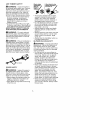
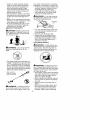
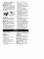
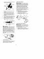
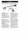
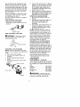
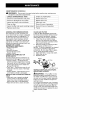
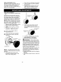
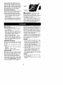
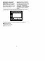
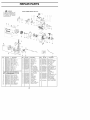
Operator's
Manual
ICRRFTSIVlRN°I
32cc/1.9 cu.in. 2-Cycle
17 Inch Cutting Path / 0.080 Inch Line
GASOLINE
WEEDWAOKER
®
Model No.
358.791041
•
Safety
• Assembly
•
•
Operation
Maintenance
•
Parts List
°
Espa_ol,
p. 22
WARNING:
Read and follow all Safety Rules and Operating
Instructions
before first use of this product.
For answers
Call 7 am-7
to your questions about this product:
pm, Mon.-Sat.,
or 10 am-7 pm, Sun.
1-800-235-5878
Sears,
Roebuck
545154230
(Hours
and Co., Hoffman
Rev. 1
7/3/07
BRW
listed are Central Time)
Estates,
IL 60179 U.S.A.
Warranty
Statement
2
Identification of Symbols
Safety Rules
Assembly
Operation
Maintenance
Service & Adjustments
2
3
8
10
14
15
ONE YEAR FULL WARRANTY
Storage
16
Troubleshooting
Table
Emissions Statement
17
18
Parts List
Spanish
Parts and Ordering
ON CRAFTSMAN
20
22
Back Cover
® GAS WEEDWACKER
®
When used and maintained according to the operator's manual, if this product fails
due to a defect in material or workmanship within one year from the date of purchase, return it to any Sears store, Sears Service Center, or other Craftsman outlet in
the United States for free repair (or replacement if repair proves impossible).
This warranty excludes cutting line, spark plug and air filter, which are expendable
parts that can wear out from normal use in less than one year.
This warranty applies for only 30 days from purchase date if this product is used
for commercial or rental purposes.
This warranty gives you specific legal rights, and you may also have other rights
which vary from state to state.
Sears, Roebuck and Co., Hoffman
Estates, IL 60179
can be dangerous! Careless or
improper use can cause
WARNING!
This trimmer
serious or even fatal injury.
Always wear
protection.
appropriate
hearing
(_
protection,
J
Read and understand the
operator's
manual
before
using the trimmer.
eye
protection
and head
_WARNIN_I:
When using gardening appliances, basic safety precautions must always be followed to
reduce the risk of fire and serious
injury. Read and follow all instructions.
This power unit can be dangerous! Operator is responsible for following
instructions and warnings on unit and in
manual. Read entire operator's manual
before using unit! Be thoroughly familiar
with the controls and the proper use of
the unit. Restrict the use of this unit to
persons who have read, understand,
and will follow the instructions and
warnings on the unit and in the manual.
Never allow children to operate this unit.
OPERATOR'S
MANUAL
SAFETY
INFORMATION
ON THE UNIT
Z_
DANGER:
Never use blades
with line trimmer attachment. Never
use flailing devices with any attachment. This unit (when used with supplied line trimmer attachment) is designed for line trimmer use only. Use
of any other accessories with line trimmer attachment will increase the risk
of injury.
_WARNING:
Trimmer line throws
objects violently. You and others can be
blinded/injured. Wear eye and leg
protection. Keep body parts clear of rotating line.
Eye Protection
/
Hazard 7one
IE,: oots
A(}/LWARNING:
Hazard zone for
thrown objects. Trimmer line can
throw objects violently. Others can be
blinded or injured. Keep children, bystanders, and animals 50 feet (15 meters) away. Stop unit immediately if approached.
If situations occur which are not covered in this manual, use care and
good judgment.
If you need assistance, contact your Sears Service
Center or call 1-800-235-5878.
OPERATOR SAFETY
• Dress properly. Always wear safety
glasses or similar eye protection
when operating, or performing maintenance, on your unit (safety
glasses are available). Eye protection should be marked Z87.
• Always wear face or dust mask if operation is dusty.
• Always wear heavy, long pants, long
sleeves, boots, and gloves. Wearing
safety leg guards is recommended.
• Always wear foot protection. Do not
go barefoot or wear sandals. Stay
clear of spinning line.
• Secure hair above shoulder length.
Secure or remove loose clothing or
clothing with loosely hanging ties,
straps, tassels, etc. They can be
caught in moving parts.
• Being fully covered also helps protect you from debris and pieces of
toxic plants thrown by spinning line.
• Stay Alert. Do not operate this unit
when you are tired, ill, upset or under the influence of alcohol, drugs,
or medication. Watch what you are
doing; use common sense.
• Wear hearing protection.
• Never start or run inside a closed
room or building. Breathing exhaust
fumes can kill.
• Keep handles free of oil and fuel.
• Always keep engine on the right
hand side of your body.
• Hold the unit firmly with both hands.
• Keep trimmer head (or other optional attachment) below waist level and
away from all parts of your body. Do
not raise engine above your waist.
• Keep all parts of your body away
from muffler and spinning line (or
other optional attachment). A hot
muffler can cause serious burns.
• Keep firm footing and balance. Do
not overreach or use from unstable
surfaces such as ladders, trees,
steep slopes, rooftops, etc.
• Use only in daylight or good artificial
light.
• Use only for jobs explained in this
manual (or manuals for optional attachments).
UNIT / MAINTENANCE
SAFETY
_WARNING:
Stop unit and disconnect the spark plug before performing maintenance
(except carburetor adjustments).
• Look for and replace damaged or
loose parts before each use. Look
for and repair fuel leaks before use.
Keep in good working condition.
• Replace trimmer head parts that are
chipped, cracked, broken, or damaged in any other way before using
the unit.
• Maintain unit according to recommended procedures. Keep cutting
line at proper length.
• Use only Craftsman® brand replacement line. Never use wire, rope,
string, etc.
• Install required shield properly before
using the unit. Use only specified trimmer head; make sure it is properly
installed and securely fastened.
• Make sure unit is assembled correctly as shown in this manual.
• Make carburetor adjustments with
lower end supported to prevent line
from contacting any object.
• Keep others away when making carburetor adjustments.
• Use only recommended
Craftsman
accessories and replacement parts.
• Have all maintenance and service
not explained in this manual performed by a Sears Service Center.
FUEL SAFETY
• Mix and pour fuel outdoors.
• Keep away #om sparks or flames.
• Do not smoke or allow smoking near
fuel or the unit or while using the unit.
• Avoid spilling fuel or oil. Wipe up all
fuel spills before starting engine.
• Move at least 10 feet (3 meters)
away from fueling site before starting engine. Stop engine and allow it
to cool before removing fuel cap.
• Empty the fuel tank before storing or
transporting the unit. Use up fuel left
in the carburetor by starting the engine and letting it run until it stops.
• Store unit and fuel in area where fuel
vapors cannot reach sparks or open
flames from water heaters, electric
motors or switches, furnaces, etc.
• Always store gasoline in a container
approved for flammable liquids.
TRANSPORTING
AND STORAGE
• Stop the unit before carrying.
• Allow engine to cool before storing
or transporting in vehicle.
• Empty the fuel tank before storing or
transporting the unit. Use up fuel left
in the carburetor by starting the engine and letting it run until it stops.
• Store unit and fuel in area where
fuel vapors cannot reach sparks or
open flames from water heaters,
electric motors or switches, furnaces,
etc.
• Store unit so line limiter blade cannot accidentally cause injury. The
unit can be hung by the shaft.
• Store unit out of reach of children.
This unit is not equipped with an antivibration system and is intended for
occasional use only.
SAFETY NOTICE: Exposure to vibrations through prolonged use of gasoline powered hand tools could cause
blood vessel or nerve damage in the
fingers, hands, and joints of people
prone to circulation disorders or abnormal swellings. Prolonged use in
cold weather has been linked to blood
vessel damage in otherwise healthy
people. If symptoms occur such as
numbness, pain, loss of strength,
change in skin color or texture, or loss
of feeling in the fingers, hands, or
joints, discontinue the use of this tool
and seek medical attention. An antivibration system does not guarantee
the avoidance of these problems. Users who operate power tools on a continual and regular basis must monitor
closely their physical condition and the
condition of this tool.
SPECIAL NOTICE: This unit is
equipped with a temperature limiting
muffler and spark arresting screen
which meets the requirements of California Codes 4442 and 4443. All U.S.
forest land and the states of California,
Idaho, Maine, Minnesota, New Jersey,
Oregon, and Washington require by
law that many internal combustion engines be equipped with a spark arresting screen. If you operate in a locale
where such regulations exist, you are
legally responsible for maintaining the
operating condition of these parts.
Failure to do so is a violation of the
law. For normal homeowner use, the
muffler and spark arresting screen will
not require any service. After 50 hours
of use, we recommend that your muffler be serviced or replaced by a
Sears Service Center.
LINE
TRIMMER
SAFETY
,_ WARNING:
Inspect the area to
be trimmed before each use. Remove
objects (rocks, broken glass, nails,
wire, etc.) which can be thrown by or
become entangled in line. Hard objects can damage the trimmer head
and be thrown causing serious injury.
• Only use the trimmer attachment for
trimming, scalping, mowing and
sweeping. Do not use the trimmer
attachment for edging, pruning or
hedge trimming.
• Cut only from your left to your right.
Cutting on right side of the shield will
throw debris away from the operator.
ADDITIONAL
SAFETY
RULES
FOR OPTIONAL ATTACHMENTS
,_/LWARNING:
For each optional
attachment used, read entire operators manual before use and follow all
warnings and instructions in manual
and on attachment.
m_WARNING:
Ensure handlebar is
installed when using edger or brushcutter attachments. Attach handlebar
above arrow on safety label on the upper shaft (engine end of unit). If your
edger or brushcutter attachment does
not include a handlebar, a handlebar
accessory kit (#530071451) is available from your Sears Service Center.
Handlebar
EDGER SAFETY
,_ WARNING:
Inspect the area to
be edged before each use. Remove
objects (rocks, broken glass, nails,
wire, etc.) which can be thrown by the
blade or can wrap around the shaft.
• Blade rotates momentarily after the
trigger is released. The blade can
seriously cut you or others.
• Allow blade to stop before removing
it from the cut.
Blade rotates
momentatlly _
after the
/
tdgger is /
Allow blade to stop
re/e_@
• Throw away blades that are bent,
warped, cracked, broken or damaged in any other way. Replace
parts that are cracked, chipped, or
damaged before using the unit.
• Do not attempt to remove cut material nor hold material to be cut when
the engine is running or when cutting blade is moving.
• Always keep the wheel and depth
adjusting skid in contact with the
ground.
• Always push the unit slowly over the
ground. Stay alert for uneven sidewalks, holes in the terrain, large
roots, etc.
• Always use the handlebar when using edger attachment.
BLOWER/VACUUM
SAFETY
WARNING:
Inspect area before
starting unit. Remove all debris and
hard objects such as rocks, glass,
wire, etc. that can ricochet, be thrown,
or otherwise cause injury or damage
during operation.
• Do not set unit on any surface except a clean, hard area while engine
is running. Debris such as gravel,
sand, dust, grass, etc., could be
picked up by the air intake and
thrown out through discharge opening, damaging unit, property, or
causing serious injury to bystanders
or operator.
• Never place objects inside the blower tubes, vacuum tubes or blower
outlet. Always direct the blowing debris away from people, animals,
glass, and solid objects such as
trees, automobiles, walls, etc. The
force of air can cause rocks, dirt, or
sticks to be thrown or to ricochet
which can hurt people or animals,
break glass, or cause other damage.
• Never run unit without the proper
equipment attached. When using
your unit as a blower, always install
blower tubes.
• Check
airintake
opening,
blower
tubes
orvacuum
tubes
frequently,
always
withengine
stopped
and
spark
plugdisconnected.
Keep
vents
anddischarge
tubes
freeof
debris
which
canaccumulate
and
restrict
proper
airflow.
• Never
place
anyobject
inairintake
opening
asthiscouldrestrict
proper
airflowandcause
damage
tothe
unit.
• Never
useforspreading
chemicals,
fertilizers,
orother
substances
which
maycontain
toxicmaterials.
• Toavoid
spreading
fire,donotuse
nearleaforbrush
fires,
fireplaces,
barbecue
pits,ashtrays,
etc.
BRUSHCUTTER
SAFETY
_/L DANGER:
Blade can thrust vio-
lently away from material it does not
cut. Blade thrust can cause amputation of arms or legs.
m_WARNIN_I:
Do not use trimmer
head as a fastening device for the
blade.
• The blade continues to spin after the
throttle is released or engine is turned
off. The coasting blade can throw objects or seriously cut you if accidentally touched. Stop the blade by contacting the right hand side of the coasting
blade with material already cut.
bSlt°dPeC_ySt
inn?act
.
with cut mater.__
,_ WARNING:
Inspect the area to
be cut before each use. Remove objects (rocks, broken glass, nails, wire,
etc.) which can be thrown or become
entangled in the blade or trimmer line.
• Throw away and replace blades that
are bent, warped, cracked, broken
or damaged in any other way.
• Install required shield properly before using the unit. Use the metal
shield for all metal blade use.
WARNING:
Only use brushcutter attachments that provide a metal
shield with protruding nose.
Protrudin g
• Use only specified blade and make
sure it is properly installed and securely fastened.
• Cut from your left to your right.
• Always use the handlebar and a
properly adjusted shoulder strap
with blade (see ASSEMBLY instructions in brushcutter attachment
operator's manual).
CULTIVATOR SAFETY
'_ WARNING:
Rotating tines can
cause serious injury. Keep away from
rotating tines. Stop the engine and
disconnect the spark plug before unclogging tines or making repairs.
,_ WARNING:
Inspect the area to
be cultivated before starting the unit.
Remove all debris and hard and sharp
objects such as rocks, vines, branches, rope, string, etc.
• Avoid heavy contact with solid objects
that might stop the tines. If heavy contact occurs, stop the engine and inspect the unit for damage.
• Never operate the cultivator without
the tine cover in place and properly
secured.
• Keep the tines and guard clear of
debris.
• After striking a foreign object, stop
the engine, disconnect the spark
plug and inspect the cultivator for
damage. Repair before restarting.
• Disconnect
attachment
fromthedrive
engine
before
cleaning
thetines
with
ahose
andwater
toremove
any
build-up.
Oilthetines
toprevent
rust.
• Always
wear
gloves
when
servicing
or
cleaning
thetines.
Thetinesbecome
verysharp
fromuse.
• Donotrununitathighspeed
unless
cultivating.
HEDGE
TRIMMER
SAFETY
DANGER:
RISK
OFCUT;
KEEP
HANDS
AWAY
FROM
BLADE
- Blade
moves
momentarily
after
thetrigger
is
released.
Donotattempt
toclear
away
cutmaterial
when
theblade
isinmotion.Make
suretheswitch
isintheOFF
position,
thespark
plugwireisdisconnected,
andtheblade
hasstopped
moving
before
removing
jammed
materialfromthecutting
blade.
Donotgrab
orholdtheunitbythecutting
blade.
Blades move
momentarily
after the
dtriggeris
Allow blades to stop
before removing
them from the cut.
_/L WARNING:
Inspect the area before starting the unit. Remove all debris and hard objects such as rocks,
glass, wire, etc. that can ricochet, be
thrown, or otherwise cause injury or
damage during operation.
• Do not use a cutting blade that is
bent, warped, cracked, broken or
damaged in any other way. Have
worn or damaged parts replaced by
your Sears Service Center.
• Always keep unit in front of your
body. Keep all parts of your body
away from the cutting blade.
• Keep the cutting blade and air vents
clear of debris.
POLE PRUNER
SAFETY
_/LWARNING:
The reciprocating
blade/rotating chain can cause severe
injury. Inspect the unit before use. Do
not operate unit with a bent, cracked
or dull blade or dull chain. Keep away
from the blade/chain.
WARNING:
The reciprocating
blade/rotating chain is sharp. Do not
touch. To prevent serious injury, always
stop engine and ensure blade/chain
has stopped moving, disconnect spark
plug, and wear gloves when changing
or handling the blade or chain.
,_ WARNING:
A coasting blade/rotating chain can cause injury while it
continues to move after the engine is
stopped. Maintain proper control of the
unit until the blade/chain has completely
stopped moving. Keep hands, face and
feet at a distance from all moving parts.
Do not attempt to touch or stop the
blade or chain when it is moving.
_/LWARNING:
Falling objects can
cause severe head injury. Wear head
protection when operating this unit
with a pole pruner attachment.
WARNING:
To prevent serious
injury, do not use more than one boom
extension with a pole pruner attachment.
WARNING:
Keep the pruner
away from power lines or electrical
wires.
• Only use for pruning limbs or
branches up to 4 inches (10 cm) in
diameter.
• Do not operate the unit faster than
the speed needed to prune. Do not
run the unit at high speed when not
pruning.
• Always stop the unit when work is
delayed or when walking from one
cutting location to another.
• If you strike or become entangled
with a foreign object, stop the engine
immediately and check for damage.
Have any damage repaired by a
Sears Service Center before attempting further operations. Discard
blades that are bent, warped,
cracked or broken.
• Stop the unit immediately if you feel
excessive vibration. Vibration is a
sign of trouble. Inspect thoroughly
for loose nuts, bolts or damage
before
continuing.
Contact
Sears
Service
forrepair
orreplacement
of
affected
parts
asnecessary.
SNOW
THROWER
SAFETY
'_LWARNING:
Keep hands and
feet away from the rotor when starting
or running the engine. Never attempt
to clear the rotor with the engine/motor
running. Stop engine and disconnect
spark plug before unclogging snow or
debris from discharge chute or when
adjusting vanes.
•
•
•
•
•
•
•
_WARNING:
Never lean over discharge chute. Rocks or debris could
be thrown into the eyes and face and
cause serious injury or blindness.
•
•
the terrain and other hidden hazards.
Make sure the rotor will spin freely
before attaching the snowthrower to
the powerhead.
If the rotor will not rotate freely due
to frozen ice, thaw the unit thoroughly before attempting to operate
under power.
Keep the rotor clear of debris.
Do not throw snow near other
people. The snow thrower could
propel small objects at high speed
causing injury.
After striking a foreign object, stop
the engine, disconnect spark plug
and inspect the snowthrower for
damage and repair if necessary before restarting unit.
Never operate the snowthrower near
glass enclosures, automobiles and
trucks.
Never attempt to use the snowthrower on a roof.
Never operate the snowthrower near
window wells, dropoffs, etc.
Never discharge snow onto public
roads or near moving traffic.
Clear snow from slopes by going up
and down; never across. Use caution when changing directions. Never clear snow from steep slopes.
Let snowthrower run for a few minutes after clearing snow so moving
parts do not freeze.
Look behind and use care when
backing up. Exercise caution to
avoid slipping or falling, especially
when operating in reverse.
Know how to stop quickly.
,_WARNING:
Inspect the area
where the unit is to be used. Remove
objects that could be thrown or damage the unit. Some objects may be
hidden by fallen snow -- be alert for
the possibility.
• Direct material discharge away from
glass enclosures, automobiles, etc.
• Do not run engine at high speed
while not removing snow.
• Be attentive when using the snowthrower, and stay alert for holes in
•
CARTON
Finding fuel or oil residue on muffler is
normal due to carburetor adjustments
and testing done by the manufacturer.
ASSEMBLY
CONTENTS
Check carton contents against the following list.
Model 358.791041
• Powerhead
• Trimmer attachment
• Shield
• Wing Nut (screwed onto shield)
• Container of line
• Container of oil
Examine parts for damage. Do not
use damaged parts.
NOTE: If you need assistance or find
parts missing or damaged, call
1-800-235-5878.
It is normal for the fuel filter to rattle in
the empty fuel tank.
•
•
•
,_ WARNING:
Always stop unit
and disconnect spark plug before performing any assembly procedures.
,_
WARNING:
If received as-
sembled, repeat all steps to ensure
your unit is properly assembled and all
fasteners are secure.
INSTALLING
MENT
TRIMMER
ATTACH-
CAUTION:
When installing trimmer
attachment, place the unit on a flat
surface for stability.
Loosen the coupler by turning the
knob counterclockwise.
1,
Coupler
LOOSEN
Shipping
protector
Knob
TIGHTEN
2.
Remove shipping protector from
coupler.
3. Remove the shaft cap from the
trimmer attachment (if present).
4. Position locking/release
button of
attachment into guide recess of
coupler.
5. Push the attachment into the coupler until the locking/release
button
snaps into the primary hole.
6. Before using the unit, tighten the
knob securely by turning clockwise.
Coupler
Primary Hole
_/
Guide Recess
u
Upper
Shaft
Locking/
Release
Button
"
"
Attachment
_WARNING:
Make surethe locking/release button is locked in the primary hole and the knob is securely
tightened before operating the unit. All
attachments are designed to be used in
the primary hole unless otherwise
stated in the applicable attachment operator's manual. Using the wrong hole
could lead to serious injury or damage
to the unit.
Locking/Release
Button in Primary Hole
For optional attachments, see the ASSEMBLY section of the applicable attachment operator's manual.
ATTACHING
SHIELD
,_IkWARNING:
The shield must be
properly installed. The shield provides
partial protection from the risk of thrown
objects to the operator and others and
is equipped with a line limiter blade
which cuts excess line to the proper
length. The line limiter blade (on underside of shield) is sharp and can cut you.
For proper orientation of shield, see
KNOW YOUR TRIMMER illustration in OPERATION section.
1. Remove wing nut from shield.
2. Insert bracket into slot as shown.
3. Pivot shield until bolt passes
through hole in bracket.
4. Securely tighten wing nut onto bolt.
Shield
Slot
PIVOT
Bracket
//
Line Limiter
Blade
\
Wing
Nut
ADJUSTING
THE HANDLE
WARNING:
When adjusting the
assist handle, be sure it remains above
the safety label and below the mark or
arrow on the shaft.
1. Loosen wing nut on handle.
2. Rotate the handle on the shaft to an
upright position; retighten wing nut.
KNOW
YOUR
TRIMMER
READ
THIS
OPERATOR'S
MANUAL
AND
SAFETY
RULES
BEFORE
OPERATING
YOUR
UNIT.
Compare
theillustrations
withyourunittofamiliarize
yourself
withthelocation of
the various controls and adjustments.
Save this manual for future reference.
Assist Handle
J
Coupler
Trimmer
Head
Shaft
\
_,
ON/OFF
Shield
Starter Handle
/
4,
t_
JPrimer Bulb
Throttle
Trigger
Line Limiter
Blade
Start Lever
ON/OFF SWITCH
The ON/OFF switch is located on the
trigger handle and is used to stop the
engine. Move the switch to the OFF
position to stop the engine.
PRIMER BULB
The PRIMER BULB removes air from
the carburetor and fuel lines and fills
them with fuel. This allows you to start
the engine with fewer pulls on the
starter rope. Activate the primer bulb
by pressing it and allowing it to return
to its original form.
BEFORE
STARTING
Switch
ENGINE
_WARNIN_I:
Be sureto read
the fuel information in the safety rules
before you begin. If you do not understand the safety rules, do not attempt
to fuel your unit. Call 1-800-235-5878.
FUELING ENGINE
_,WARNING:
Remove fuel cap
slowly when refueling.
This engine is certified to operate on
unleaded gasoline. Before operation,
gasoline must be mixed with a good
quality synthetic 2-cycle air-cooled engine oil. We recommend Craftsman
brand synthetic oil. Mix gasoline and oil
at a ratio of 40:1. A 40:1 ratio is obtained by mixing 3.2 ounces of oil with 1
Muffler
START LEVER
The START LEVER helps to supply fuel
to the engine to aid in starting. Activate the starting system by moving the
start lever to the START position. DO
NOT squeeze the throttle trigger until
the engine has started and runs. After
the engine starts, allow the engine to
warm-up 5 seconds, then fully
squeeze the throttle trigger to deactivate the starting system (start lever
returns to RUN position).
COUPLER
The COUPLER enables optional attachments to be installed on the unit.
gallon of unleaded gasoline. Included
with this trimmer is a 3.2 ounce container of oil. Pour the entire contents of this
container into 1 gallon of gasoline to
achieve the proper fuel mixture. DO
NOT USE automotive oil or marine oil.
These oils will cause engine damage.
When mixing fuel, follow instructions
printed on container.
Once oil is added to gasoline, shake
container momentarily to assure that
the fuel is thoroughly mixed. Always
read and follow the safety rules relating to fuel before fueling your unit.
IMPORTANT
Alcohol blended fuels (called gasohol
or using ethanol or methanol) can attract moisture which leads to separation and formation of acids during stor10
age.Acidic
gascandamage
thefuel
5. This unit has the Sim-pulTM starting
system
ofanengine
whileinstorage.
system. You do not have to pull the
starter rope handle sharply or briskToavoidengine
problems,
empty
the
ly. Pull starter rope handle with a
fuelsystem
before
storage
for30days
controlled and steady motion until
orlonger.
Drain
thegastank,
startthe
starts and runs.
engine
andletitrununtilthefuellines 6. engine
Allow unit to run for 5 seconds, then
andcarburetor
areempty.
Usefresh
fuelnextseason.
fully squeeze the throttle trigger to
disengage the starting system (start
Never
useengine
orcarburetor
cleanlever returns to RUN position).
erproducts
inthefueltankorpermaSTARTING A WARM ENGINE
nentdamage
mayoccur.
SeetheSTORAGE
section
foraddition- 1. Move ON/OFF switch to the ON
alinformation.
position.
2. Squeeze and hold the throttle trigHOW
TOSTOP
YOUR
UNIT
ger. Keep throttle trigger fully
• Release
thethrottle
trigger.
squeezed until engine runs
• Move
theON/OFF
switch
totheOFF
smoothly.
position.
3. Pull starter rope handle with a con-
ON/OFF
Switch
HOW
TOSTART
YOUR
UNIT
,_/LWARNING:
Avoid any contact
with the muffler. A hot muffler can
cause serious burns.
_
STARTING
* rtin Position
A COLD ENGINE
NOTE: DO NOT squeeze the throttle
trigger until the engine has started and
runs.
1. Set unit on a flat surface.
2. Move ON/OFF switch to the ON
position.
3. Slowly press the primer bulb 6
times.
4. Move the start lever to the START
position.
_s Starter Handle
Start
Primer Bulb
Muffler
trolled and steady motion while
squeezing throttle trigger until engine starts and runs.
NOTE: Normally, the warm starting
procedure can be used within 5-10
minutes after the unit is turned off. If
the unit sits for more than 10 minutes
without being used, it will be necessary to start the unit by following the
steps under STARTING A COLD ENGINE or following the starting instruction steps shown on the unit.
STARTING A FLOODED ENGINE
Flooded engines can be started by
placing the ON/OFF switch in the ON
position. Move the start lever to the
RUN position and fully squeeze throttle
trigger. Pull the starter rope handle repeatedly while squeezing throttle trigger until engine starts and runs. This
could require pulling the starter rope
handle many times, depending on
how badly the unit is flooded.
If the unit still doesn't start, refer to
TROUBLESHOOTING TABLE or call
1-800-235-5878.
CRAFTSMAN ®
CONVERTIBLE
FEATURE
TM
This model is equipped with a coupler
which enables optional attachments to
be installed. The optional attachments
are:
Edger .................
358.79240
Cultivator ..............
358.79241
Blower ................
358.79242
Brushcutter
............
358.79244
Pruner ................
358.79245
,_ WARNING:
Always stop unit
and disconnect spark plug before removing or installing attachments.
11
REMOVING TRIMMER ATTACHMENT (OR OTHER OPTIONAL ATTACHMENTS)
CAUTION:
When removing or installing attachments,
place the unit on a
flat surface for stability.
1. Loosen the coupler by turning the
knob counterclockwise.
erator's manual. Using the wrong hole
could lead to serious injury or damage
to the unit.
Secondary
Hole
Upper Shaft
Coupler
LOOSEN
Attachment
TIGHTEN
2,
Press and
button.
hold the
Knob
locking/release
Locking/Release
Button
Cou[
Hole
OPERATING
INSTRUCTIONS
To maximize operating efficiency, do
not run the engine for longer than 1
minute at a time at full throttle.
OPERATING POSITION
ALWAYS USE:
Hearing
Protection _.-i
Eye Protection
Upper Shaft
Attachment
3.
While securely holding the engine
and upper shaft, pull the attachment straight out of the coupler.
INSTALLING OPTIONAL ATTACHMENTS
1. Remove the shaft cap from the attachment (if present).
2. Position locking/release
button of
attachment into guide recess of
coupler.
3. Push the attachment into the coupler until the locking/release
button
snaps into the primary hole.
4. Before using the unit, tighten the
knob securely by turning clockwise.
Couple r Primary Hole
Guide Recess
Upper
Shaft
Locking/Release
Button in Primary
Locking/
Release
Button
Attachment
_I, WARNING:
Make surethe locking/release button is locked in the primary hole and the knob is securely
tightened before operating the unit. All
attachments are designed to be used in
the primary hole unless otherwise
stated in the applicable attachment op-
Long
Pants
Heavy
Shoes
_
Cut from your right to your left.
WARNING:
Always wear eye
protection and hearing protection. Never
lean over the trimmer head. Rocks or
debris can ricochet or be thrown into
eyes and face and cause blindness or
other serious injury.
When operating unit, stand as shown
and check for the following:
• Wear eye protection, hearing protection and heavy clothing.
• Hold trigger handle with right hand
and assist handle with left hand.
• Hold unit so that engine is below
waist level.
• Cut only from your right to your left
to ensure debris is thrown away from
you. Without bending over, keep line
near and parallel to the ground and
not crowded into material being cut.
Do not run the engine at a higher speed
than necessary. The cutting line will cut
efficiently when the engine is run at less
than full throttle. At lower speeds, there
is less engine noise and vibration.
12
Always
release
thethrottle
trigger
and
allow
theengine
toreturn
toidle
speed
whennotcutting.
HOW
TOSTOP
YOUR
UNIT
• Release
thethrottle
trigger.
• Move
theON/OFF
switch
totheOFF
position.
CUTTING
METHODS
,_WARNING:
SCALPING - The scalping technique
removes unwanted vegetation down to
the ground. Hold the bottom of the trimmer head about 3 inches (8 cm) above
the ground and at an angle. Allow the
tip of the line to strike the ground
around trees, posts, monuments, etc.
This technique increases line wear.
Use minimum
speed and do not crowd the line when
cutting around hard objects (rock,
gravel, fence posts, etc.), which can
damage the trimmer head, become
entangled in the line, or be thrown
causing a serious hazard.
• The tip of the line does the cutting.
You will achieve the best performance and minimum line wear by not
crowding the line into the cutting
area. The right and wrong ways are
shown below.
Tip of the Line
Line Crowded Into
Does The Cutting
Work Area
Scalping
3 inches (8 cm)
above ground
MOWING - Your trimmer is ideal for
mowing in places conventional lawn
mowers cannot reach. In the mowing
position, keep the line parallel to the
ground. Avoid pressing the head into
the ground as this can scalp the
ground and damage the tool.
Mowing
Right
Wrong
• The line will easily remove grass
and weeds from around walls,
fences, trees and flower beds, but it
also can cut the tender bark of trees
or shrubs and scar fences.
• For trimming or scalping, use less
than full throttle to increase line life
and decrease head wear, especially:
• During light duty cutting.
• Near objects around which the line
can wrap such as small posts,
trees or fence wire.
TRIMMING - Hold the bottom of the
trimmer head about 3 inches (8 cm)
above the ground and at an angle. Allow only the tip of the line to make
contact with vegetation. Do not force
trimmer line into work area.
SWEEPING - The fanning action of the
rotating line can be used to blow away
loose debris from an area. Keep the line
parallel to and above the area surface
and swing the tool from side to side.
Sweeping
Trimming
3 inches (8 cm)
above ground
13
MAINTENANCE
SCHEDULE
WARNING:
Disconnect the spark plug before performing maintenance
except for carburetor adjustments.
CARE & MAINTENANCE TASK
WHEN TO PERFORM
Check for loose fasteners
Check for damaged
Before each use
and parts
Before each use
or worn parts
After each use
Inspect and clean unit and decals
Clean air filter
Inspect muffler and spark arresting
Replace
Every 5 hours of operation
screen
Every 50 hours of operation
spark plug
GENERAL RECOMMENDATIONS
The warranty on this unit does not
cover items that have been subjected
to operator abuse or negligence. To
receive full value from the warranty,
the operator must maintain unit as
instructed in this manual. Various adjustments will need to be made periodically to properly maintain your unit.
CHECK FOR LOOSE
FASTENERS AND PARTS
• Spark Plug Boot
• Air Filter
• Housing Screws
• Assist Handle Screw
• Debris Shield
CHECK FOR DAMAGED
OR
WORN PARTS
Contact Sears Service Center for replacement of damaged or worn parts.
• ON/OFF Switch - Ensure ON/OFF
switch functions properly by moving
the switch to the OFF position. Make
sure engine stops; then restart engine and continue.
• Fuel Tank - Discontinue use of unit
if fuel tank shows signs of damage
or leaks.
• Debris Shield - Discontinue use of
unit if debris shield is damaged.
INSPECTAND
CLEAN UNITAND DECALS
• After each use, inspect complete
unit for loose or damaged parts.
Clean the unit and decals using a
damp cloth with a mild detergent.
• Wipe off unit with a clean dry cloth.
Yearly
CLEAN AIR FILTER
A dirty air filter decreases engine performance and increases fuel consumption and harmful emissions. Always
clean after every 5 hours of operation.
1. Clean the cover and the area
around it to keep dirt from falling
into the carburetor chamber when
the cover is removed.
2. Remove parts by pressing button
to release air filter cover.
NOTE: To avoid creating a fire hazard
or producing harmful evaporative
emissions, do not clean filter in gasoline or other flammable solvent.
3. Wash the filter in soap and water.
4. Allow filter to dry.
5. Replace parts.
Button
Air Filter
Air Filter Cover
INSPECT MUFFLER AND SPARK
ARRESTING
SCREEN
_/L WARNING:
The muffler on this
product contains chemicals known to
the State of California to cause cancer.
As your unit is used, carbon deposits
build up on the muffler and spark arresting screen.
For normal homeowner use, however,
the muffler and spark arresting screen
will not require any service. After 50
hours of use, we recommend that your
muffler be serviced or replaced by your
Sears Service Center.
14
REPLACE SPARK PLUG
Replace the spark plug each year to
ensure the engine starts easier and
runs better. Set spark plug gap at
0.025 inch (0.6 mm). Ignition timing is
fixed and nonadjustable.
1.
2.
3.
4.
LINE REPLACEMENT
• Always use Craftsman replacement
line.
Choose the line size best suited for
the job at hand. Red line is designed
for cutting grass and small weeds.
The black colored line is designed for
cutting larger weeds and light brush.
NOTE: Before inserting new line into
the holes in the cutting head, identify
the proper holes. Follow directions as
shown on the line glide plate.
1. Remove the old line and line glide
plate from the cutting head.
2. Clean entire surface of cutting
head.
3. Reinstall line glide plate (see illustration). Align arrow with:
(_)
Twist, then pull off spark plug boot.
Remove spark plug from cylinder
and discard.
Replace with Champion RCJ-6Y
spark plug and tighten securely
with a 3/4 inch socket wrench.
Reinstall the spark plug boot.
Positioning
5,
!
Pull the line and make sure the
line is against the hub and extended full through the positioning
tunnels.
Line against
the hub
Positioning
Tunnel \
when using medium (red) or
large (black)line
when using lines with diameter
(_) smaller than medium (red) line
(optional)
6.
Correctly installed line will be the
same length on both ends.
CARBURETOR
ADJUSTMENT
Line glide
plate
Arrow
Cutting head
NOTE: Line glide plate must be reinstalled in cutting head before inserting
new line.
4. Insert both ends of your line
through the proper holes in the
side of the cutting head.
WARNING:
Keep others away
when making idle speed adjustments.
The trimmer head will be spinning during most of this procedure. Wear your
protective equipment and observe all
safety precautions. After making adjustments, the trimmer head must not
move or spin at idle speed.
The carburetor has been carefully set
at the factory. Adjustments may be
necessary if you notice any of the following conditions:
• Engine will not idle when the throttle is
released.
• The trimmer head moves or spins at
idle.
15
Make adjustments with the unit supported so the cutting attachment is off
the ground and will not make contact
with any object. Hold the unit by hand
while running and making adjustments.
Keep all parts of your body away from
the cutting attachment and muffler.
Idle Speed Adjustment
Allow engine to idle. Adjust speed until
engine runs without trimmer head
moving or spinning (idle too fast) or
engine stalling (idle speed too slow).
• Turn idle speed screw clockwise to
increase engine speed if engine
stalls or dies.
• Turn idle speed screw counterclockwise to decrease engine speed if
trimmer head moves or spins at idle.
_WARNING:
Perform the following steps after each use:
• Allow engine to cool before storing
or transporting.
• Store unit and fuel in a well ventilated area where fuel vapors cannot
reach sparks or open flames from
water heaters, electric motors or
switches, furnaces, etc.
• Store unit with all guards in place.
Position unit so that any sharp object cannot accidentally cause injury.
• Store unit and fuel well out of the
reach of children.
SEASONAL STORAGE
Prepare unit for storage at end of season or if it will not be used for 30 days
or more.
If your unit is to be stored for a period
of time:
• Clean the entire unit before lengthy
storage.
• Store in a clean dry area.
• Lightly oil external metal surfaces.
FUEL SYSTEM
Empty the fuel system before storage
for 30 days or longer. Drain the gas
tank, start the engine and let it run until the fuel lines and carburetor are
empty. Use fresh fuel next season.
Under FUELING ENGINE in the OPERATION section of this manual, see message labeled IMPORTANT regarding
the use of gasohol in your engine.
Air Filter
Cover
Idle Speed
Screw
WARNING:
Recheck the idle
speed after each adjustment.
The
trimmer head must not move or spin at
idle speed to avoid serious injury to
the operator or others.
If you require further assistance or are
unsure about performing this procedure, contact your Sears Service Center or call our customer assistance
help line at 1-800-235-5878.
Fuel stabilizer is an acceptable alternative in minimizing the formation of
fuel gum deposits during storage. Add
stabilizer to the gasoline in the fuel
tank or fuel storage container. Follow
the mix instructions found on stabilizer
container. Run engine at least 3 minutes after adding stabilizer.
Craftsman 40:1,2-cycle
engine oil (air
cooled) is already blended with fuel
stabilizer. If you do not use this Sears
oil, you can add a fuel stabilizer to
your fuel tank.
ENGINE
• Remove spark plug and pour 1 teaspoon of 40:1,2-cycle
engine oil (air
cooled) through the spark plug
opening. Slowly pull the starter rope
8 to 10 times to distribute oil.
• Replace spark plug with new one of
recommended
type and heat range.
• Clean air filter.
• Check entire unit for loose screws,
nuts, and bolts. Replace any damaged, broken, or worn parts.
• At the beginning of the next season,
use only fresh fuel having the proper
gasoline to oil ratio.
OTHER
• Do not store gasoline from one season to another.
• Replace your gasoline can if it starts
to rust.
16
TROUBLESHOOTING
TABLE
WARNING:
Always stop unit and disconnect spark plug before performing all of the recommended
remedies below except remedies that require
unit to be operating.
TROUBLE
Engine will not
start.
REMEDY
CAUSE
1. ON/OFF switch in
OFF position.
2. Engine flooded.
1. Move ON/OFF switch to the ON
position.
2. See "Starting a Flooded Engine" in
Operation Section.
3. Fill tank with correct fuel mixture.
4. Install new spark plug.
5. Check for dirty fuel filter; replace.
Check for kinked or split fuel line;
repair or replace.
6. Contact Sears Service (see back cover).
3. Fuel tank empty.
4. Spark plug not firing.
5. Fuel not reaching
carburetor.
6. Carburetor requires
adjustment.
Engine will
not idle
properly.
1. Carburetor requires
adjustment.
2. Crankshaft seals worn.
3. Compression
low.
1. See "Carburetor Adjustment" in
Service and Adjustments
Section.
2. Contact Sears Service (see back cover).
3. Contact Sears Service (see back cover).
Engine will not
accelerate,
lacks power,
or dies under
a load.
1. Air filter dirty.
2. Spark plug fouled.
1. Clean or replace air filter.
2. Clean or replace plug
and regap.
Contact Sears Service (see back cover).
3. Carburetor requires
adjustment.
4. Carbon build-up on
muffler outlet screen.
5. Compression
low.
4. Contact Sears Service (see back cover).
5. Contact Sears Service (see back cover).
Engine
smokes
1. Fuel mixture
excessively.
2. Air filter dirty.
3. Carburetor requires
adjustment.
2. Clean or replace air filter.
3. Contact Sears Service (see back cover).
Engine
hot.
1. Fuel mixture incorrect.
1.
runs
incorrect.
1. Empty fuel tank and refill with
correct fuel mixture.
See "Fueling Engine" in Operation
section.
2. Replace with correct spark plug.
3. Contact Sears Service (see back cover).
2. Spark plug incorrect.
3. Carburetor requires
adjustment.
4. Carbon build-up on
muffler outlet screen.
4. Contact Sears Service (see back cover).
17
YOUR WARRANTY RIGHTS AND OBLIGATIONS: The U.S. Environmental
Protection Agency/California Air Resources Board and Sears, Roebuck
and Co., U.S.A., are pleased to explain
the emissions control system warranty
on your year 2007 and later small offroad engine. In California, all small offroad engines must be designed, built,
and equipped to meet the State's stringent anti-smog standards. Sears must
warrant the emission control system on
your small off-road engine for the periods of time listed below provided there
has been no abuse, neglect, or improper maintenance of your small off-road
engine. Your emission control system
includes parts such as the carburetor,
the ignition system and the fuel tank
(California only). Where a warrantable
condition exists, Sears will repair your
small off-road engine at no cost to you.
Expenses covered under warranty include diagnosis, parts and labor.
MANUFACTURER'S
WARRANTY
COVERAGE: If any emissions related
part on your engine (as listed under
Emissions Control Warranty Parts List)
is defective or a defect in the materials
or workmanship of the engine causes
the failure of such an emission related
part, the part will be repaired or replaced by Sears. OWNER'S WARRANTY RESPONSIBILITIES:
As the
small off-road engine owner, you are
responsible for the performance of the
required maintenance listed in your operator's manual. Sears recommends
that you retain all receipts covering
maintenance on your small off-road engine, but Sears cannot deny warranty
solely for the lack of receipts or for your
failure to ensure the performance of all
scheduled maintenance. As the small
off-road engine owner, you should be
aware that Sears may deny you warranty coverage if your small off-road
engine or a part of it has failed due to
abuse, neglect, improper maintenance,
unapproved modifications, or the use of
parts not made or approved by the original equipment manufacturer. You are
responsible for presenting your small
off-road engine to a Sears authorized
repair center as soon as a problem exists. Warranty repairs should be completed in a reasonable amount of time,
not to exceed 30 days. If you have any
questions regarding your warranty rights
and responsibilities, you should contact
your nearest authorized service center
or call Sears at 1-800-469-4663.
WARRANTY COMMENCEMENT
DATE: The warranty period begins on
the date the small off-road engine is
purchased. LENGTH OF COVERAGE:
This warranty shall be for a period of
two years from the initial date of purchase. WHAT IS COVERED: REPAIR
OR REPLACEMENT
OF PARTS, Repair or replacement of any warranted
part will be performed at no charge to
the owner at an approved Sears Service Center. If you have any questions
regarding your warranty rights and responsibilities, you should contact your
nearest authorized service center or call
Sears at 1-800-469-4663.
WARRANTY PERIOD: Any warranted part which
is not scheduled for replacement as required maintenance, or which is scheduled only for regular inspection to the
effect of "repair or replace as necessary" shall be warranted for 2 years.
Any warranted part which is scheduled
for replacement as required maintenance shall be warranted for the period
of time up to the first scheduled replacement point for that part. DIAGNOSIS:
The owner shall not be charged for
diagnostic labor which leads to the determination that a warranted part is defective if the diagnostic work is performed at an approved Sears Service
Center. CONSEQUENTIAL
DAMAGES: Sears may be liable for damages to other engine components
caused by the failure of a warranted
part still under warranty. WHAT IS NOT
COVERED: All failures caused by
abuse, neglect, or improper maintenance are not covered. ADD-ON OR
MODIFIED PARTS: The use of add-on
or modified parts can be grounds for
disallowing a warranty claim. Sears is
not liable to cover failures of warranted
parts caused by the use of add-on or
modified parts. HOW TO FILE A
CLAIM: If you have any questions regarding your warranty rights and responsibilities, you should contact your
nearest authorized service center or call
Sears at 1-800-469-4663.
WHERE TO
GET WARRANTY SERVICE: Warranty
services or repairs shall be provided at
all Sears Service Centers. Call
1-800-469-4663.
18
EMISSION CONTROL WARRANTY
PARTS LIST: Carburetor, Ignition System: Spark Plug (covered up to maintenance schedule), Ignition Module, Muffler including catalyst, Fuel Tank
(California only). MAINTENANCE
STATEMENT: The owner is responsible
for the performance of all required maintenance as defined in the operator's
manual.
MAINTENANCE, REPLACEMENT
AND REPAIR OF EMISSION RELATED PARTS: Any Sears approved
replacement part used in the performance of any warranty maintenance or
repair on emission related parts will be
provided without charge to the owner if
the part is under warranty.
The information on the product label indicates which standard your engine is certified.
Example: (Year) EPA Phase 1 or Phase 2 and/or CALIFORNIA.
41
This engine is certified to be emissions
[]
Moderate
[]
Intermediate
[]
Extended
I
el
compliant
(50 hours)
(125 hours)
(300 hours)
19
I
81
I
for the following
use:
REPAIR PARTS
SEARS
TRIMMER
MODEL 358.791041
7
_IL
12
WARNING
Atl repairs,
maintenance
adjustments
and
not described in
the Operator's Manual must be
performed by qualified service
personnel.
....
14
....
15
_,"..................
20
16
_
17
i
_,
I
_
21
22
18
Ref
Part No,
' 1.
2.
530015805
530015886
Screw-alignment
Screw
Description
3.
4.
5.
6.
7.
8.
530057983
530016326
530057984
530058843
530069572
530015886
Hsg.-Throttle
right
Screw-Cable
Retention
Hsg.-Left throttle
Assy-Wire
Kit-Switch
Screw
9.
10
545017701
530015786
Lever-Trigger
Bolt
11.
12.
13.
530058583
530016152
530071936
14.
15.
16.
17.
530016344
530071788
530052286
530015814
Assy-Handle
(Incl. 10,12)
Wingnut
Kit-Upper Shaft
(Incl. flex, clamp & 14)
Screw
Kit-Lower Shaft
Limiter- Line
Screw
18.
530071802
19.
530015820
Ref,
20.
21.
22.
Part
_
No,
530016152
Description
Wingnut
Head-Cutting
Tube - Twisted
Red Line
Black Line
Plate-Glide
71-85740
71-85908
71-85909
23.
23
530096039
Line
Not Shown
545154280
580056220
530057296
Kit-Shield
Assy.
(Incl. 16,17)
Bolt
20
Operator Manual
Decal-Shaft
Warning
Decal- Upper Shaft
REPAIR PARTS
A
WARNING
SEARS TRIMMER
MODEL 358.791041
All repairs, adjustments
and
maintenance not described in
the Operator's
Manual
must
be performed
by qualified
service personnel.
23
i
24
i
::
13
_
_
32
34
25
35
36
40
41
49
42
43
54
58
I
i
_3
Ref.
65
Part No.
Description
Ref,
Part No.
1.
2.
3.
530047721
530071717
530015843
Bulb-Purge
Kit-Choke
Lever
Screw-tank
530055492
530054941
530054834
Isolator-Tank
Ret.-Tank
Handle-Starter
4.
5.
6.
530049386
530014362
530071404
Cap-Fuel w/ret.
Assy-Fuel
pickup
Kit-Fuel line
7.
8.
9.
10.
11.
12.
530069216
530015775
545000501
545082301
530015849
545000601
Kit-Fuel/Purge
line
Screw
Cover-Air box
Filter-Air
Screw-Oarb.
Box-Air
24
25.
26.
27.
28.
29.
30.
31.
32.
33.
34.
545050410
545081601
530015787
530019158
530032102
530015789
Kit-Rope
Bearing-Inner
Retainer
Seal
Bearing-Outer
Ret.-Orankshaft
530028807
545081901
13.
545006017
Kit- Carb assy.(OlU
35.
545006037
36.
37.
38.
39.
40.
4t.
42.
43.
44.
45.
46.
530055524
530016030
530055620
530015775
545115201
Assy-Orankshaft
Assy-Orankcase
( Incl. 28,29,30,31)
Assy-O'case/O'shafl
( Incl. 32,33,34)
Assy- Flywheel
Washer
Spacer
Screw-Baffle
Plate-Baffle
545050408
545054901
530019t 82
Kit-Pulley
Spring-Starter
Grommet
530016386
530059278
530094189
Screw- F/hsg.
Assy- Fan Housing
Washer-Clutch
I
14.
15.
16.
17.
18.
19.
20.
21.
22.
23.
(Note: for
Hepalr
are not available
this Kits
carburetor}
545030102
545103602
530015771
530015952
545000701
545030102
530027593
530029781
530016064
530015875
Seal-Oarb.(kit)
Assy- Fuel Tank
Screw-Crankcase
Screw-Shroud
Assy- Rear Shroud
O-ring-Shroud
(kit)
Valve- Reed
Stop- Reed
Screw- Reed stop
Screw- Retainer
-W32
Description
21
Ref,
Part No.
47.
48.
49.
50.
51.
52.
530055122
530150247
530010960
530015162
530012594
530071998
53.
54.
55.
56.
57.
58.
545030102
530058846
530016387
545030102
545033201
545081871
59.
60.
6t.
62.
63.
64.
530012586
952030249
65.
545026801
530001624
530039234
530016357
545030102
Description
Assy-Clutch
Assy- Drum/Adapter
Assy-Conn,
Rod
Ret,- Piston pin
Ring-Piston
Kit-Piston
(Incl. 50,51 )
Gasket-Cylinder(kit)
Assy- Leadwire
Bolt-Muffler
1/4"-20
Gasket- Muffler (kit)
Shield
Kit-Muffler
(Incl. 55,56,57)
Cylinder
Plug-Spark(ROJ-6Y)
Bolt-Oyl. 1/4"-20
Module-ignition
Screw- Module
Kit-Gasket/Seal
(Incl. 14,19, 53,56)
Assy-Throttle
cable