1
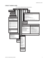
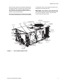
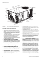
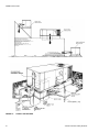
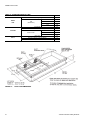
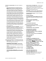
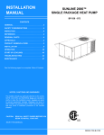
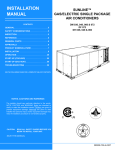
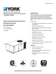
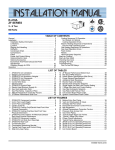
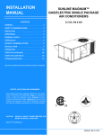
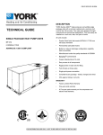
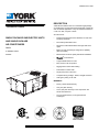
392856-YTG-C-0109
®
DESCRIPTION
YORK Sunline 2000™ units are convertible single package
air conditioners. The units were designed for light commercial
and commercial applications. They can easily be installed on
a roof curb, slab, roof jack or frame.
TECHNICAL GUIDE
All units include:
SINGLE PACKAGE GAS/ELECTRIC UNITS
AND SINGLE PACKAGE
AIR CONDITIONERS
DM072
6 NOMINAL TONS
9.0 EER
•
Powder Paint finish that meets ASTM-B-117 1000 hour
salt spray standards
•
Permanently lubricated motors
•
Direct Drive or Belt Drive Blower with high static drive
option
•
Bottom or side air discharge configuration capability
(field convertible)
•
Manufactured under the quality standards of ISO9001
•
Simplicity® Control Board
•
Copper tube/aluminum fin coils
•
Easy access to all components
•
Rigging holes in base rails for lifting
•
Fork lift slots on three sides
•
Single point power connection
•
Complete factory package - tested, charged and wired
•
CSA agency listing on all units
WARRANTY
•
Factory Limited Parts Warranty
•
One-year parts warranty
•
A Five-year parts warranty on the compressor and
electric heat elements.
•
Ten-year parts warranty on the gas-fired heat
exchangers.
FOR DISTRIBUTION USE ONLY - NOT TO BE USED AT POINT OF RETAIL SALE
392856-YTG-C-0109
TABLE OF CONTENTS
DESCRIPTION . . . . . . . . . . . . . . . . . . . . . . . . . . . . . 1
LIST OF TABLES
PRODUCT NOMENCLATURE . . . . . . . . . . . . . . . . . 3
Tbl. #
FEATURES . . . . . . . . . . . . . . . . . . . . . . . . . . . . . . . . 4
1
SOUND POWER RATING . . . . . . . . . . . . . . . . . . . . . . . 8
FACTORY-INSTALLED OPTIONS . . . . . . . . . . . . . . 6
2
CAPACITY RATINGS - (ARI 210/240) . . . . . . . . . . . . . 9
FIELD-INSTALLED ACCESSORIES . . . . . . . . . . . . 7
3
GAS HEAT RATINGS . . . . . . . . . . . . . . . . . . . . . . . . . . 9
GUIDE SPECIFICATIONS . . . . . . . . . . . . . . . . . . . 25
4
2 STAGE GAS HEAT RATINGS . . . . . . . . . . . . . . . . . . 9
5
DM072 COOLING CAPACITIES (6 TON) . . . . . . . . . . 10
6
SUPPLY AIR BLOWER PERFORMANCE (DM072
BELT DRIVE) - SIDE DUCT APPLICATION . . . . . . . . 11
7
SUPPLY AIR BLOWER PERFORMANCE (DM072
BELT DRIVE) - BOTTOM DUCT APPLICATION . . . . 11
8
SUPPLY AIR BLOWER PERFORMANCE (DM072
DIRECT DRIVE) SIDE DUCT APPLICATION . . . . . . . 11
SUPPLY AIR BLOWER PERFORMANCE (DM072
DIRECT DRIVE) BOTTOM DUCT APPLICATION . . . 11
LIST OF FIGURES
Fig. #
Pg. #
Pg. #
1
UNIT CUTAWAY GAS/ELECTRIC . . . . . . . . . . . . . . . . . 5
2
UNIT CUTAWAY ELECTRIC/ELECTRIC . . . . . . . . . . . 6
3
TYPICAL FIELD POWER & CONTROL WIRING . . . . 18
4
UNIT DIMENSIONS (6 TON COOLING ONLY/ELECTRIC HEAT) FRONT VIEW . . . . . . . . . . . . . . . . . . . . . 19
9
5
UNIT DIMENSIONS (6 TON COOLING/GAS HEAT)
FRONT VIEW . . . . . . . . . . . . . . . . . . . . . . . . . . . . . . . . 19
10 BELT DRIVE RPM SELECTION . . . . . . . . . . . . . . . . . 11
6
UNIT WITH ECONOMIZER RAINHOOD . . . . . . . . . . . 20
12 STATIC RESISTANCES . . . . . . . . . . . . . . . . . . . . . . . 12
7
UNIT WITH FIXED OUTDOOR AIR/MOTORIZED
DAMPER RAINHOOD . . . . . . . . . . . . . . . . . . . . . . . . . 20
13 ELECTRIC HEATER CFM LIMITATIONS . . . . . . . . . . 13
8
UNIT DIMENSIONS (REAR VIEW) . . . . . . . . . . . . . . . 21
9
DISCONNECT/BLOWER ACCESS LOCATION . . . . . 21
10 TYPICAL APPLICATIONS . . . . . . . . . . . . . . . . . . . . . . 22
11 FOUR AND SIX POINT LOADING . . . . . . . . . . . . . . . . 23
12 ROOF CURB DIMENSIONS . . . . . . . . . . . . . . . . . . . . 24
11 BELT DRIVE BLOWER MOTOR AND DRIVE DATA . 12
14 ELECTRICAL DATA - DM072 DIRECT DRIVE W/O
POWERED CONV. OUTLET . . . . . . . . . . . . . . . . . . . . 14
15 ELECTRICAL DATA - DM072 BELT DRIVE W/O
POWERED CONV. OUTLET . . . . . . . . . . . . . . . . . . . . 14
16 ELECTRICAL DATA - DM072 BELT DRIVE HIGH
STATIC W/O POWERED CONV. OUTLET . . . . . . . . . 15
17 ELECTRICAL DATA - DM072 DIRECT DRIVE
W/POWERED CONV. OUTLET . . . . . . . . . . . . . . . . . 15
18 ELECTRICAL DATA - DM072 BELT DRIVE W/POWERED CONV. OUTLET . . . . . . . . . . . . . . . . . . . . . . . . 16
19 ELECTRICAL DATA - DM072 BELT DRIVE HIGH
STATIC W/POWERED CONV. OUTLET . . . . . . . . . . . 16
20 PHYSICAL DATA . . . . . . . . . . . . . . . . . . . . . . . . . . . . 17
21 ELECTRIC HEAT CORRECTION FACTORS . . . . . . . 17
22 VOLTAGE LIMITATIONS . . . . . . . . . . . . . . . . . . . . . . 17
23 UTILITIES ENTRY . . . . . . . . . . . . . . . . . . . . . . . . . . . . 21
24 MINIMUM CLEARANCES . . . . . . . . . . . . . . . . . . . . . . 21
25 DM 4 AND 6 POINT LOADS WEIGHT
DISTRIBUTION . . . . . . . . . . . . . . . . . . . . . . . . . . . . . . 23
26 CENTER OF GRAVITY . . . . . . . . . . . . . . . . . . . . . . . . 23
27 OPERATING WEIGHTS (LBS.) . . . . . . . . . . . . . . . . . . 24
2
Johnson Controls Unitary Products
392856-YTG-C-0109
PRODUCT NOMENCLATURE
6 Ton Sunline Model Number Nomenclature
D M 072 N04 A 2 A AA 1 0 1 2 4 A
Product Category
Product Style
D = A/C, Single Pkg., R-22
A = Style A
Product Identifier
Configuration Options (not required for all units)
These four digits will not be assigned until a quote is requested, or an order placed.
M = 9.0 EER A/C
SS Drain Pan
CPC Controller, DFS, APS
Johnson Controller UNT 1126 (N2 protocol), DFS, APS
Nominal Cooling Capacity
Honeywell Controller, DFS, APS
072 = 6.0 Ton
Novar Controller, DFS, APS
Simplicity IntelliComfort Controller
Simplicity IntelliComfort Controller w/ModLinc
Heat Type and Nominal Heat Capacity
York Commercial Comfort System (YCCS) Rtu Controller
C00 = Cooling Only. Suitable for Field
Installed Electric Heat
2" Pleated filters
BAS Ready Economizer (2-10 V. D. C. Actuator without a Controller)
Any Combination of Additional Options that Don’t Have an Option Code Pre-assigned
Gas Heat Options
N08 = 80 MBH Output Aluminized Steel, 1 Stage
(072)
N10 = 100 MBH Output Aluminized Steel, 1 Stage
(072)
D06 = 60 MBH Output Aluminized Steel, 2 Stage
(072)
D10 = 100 MBH Output Aluminized Steel, 2 Stage
(072)
S08 = 80 MBH Output Stainless Steel, 1 Stage
(072)
S10 = 100 MBH Output Stainless Steel, 1 Stage
(072)
T06 = 60 MBH Output Stainless Steel, 2 Stage
(072)
T10 = 100 MBH Output Stainless Steel, 2 Stage
(072)
Product Generation
1 = First Generation
2 = Second Generation
3 = Third Generation
Additional Options
Electric Heat Options
E05 = 5 KW
E07 = 7 KW
E10 = 10 KW
E15 = 15 KW
E20 = 20 KW
E30 = 30 KW
Standard Cabinet
Hinged Filter Door & Toolless Access Cabinet
AA = None
AB = Phase Monitor
AC = Coil Guard
AD = Dirty Filter Switch
AE = Phase Monitor & Coil Guard
AF = Phase Monitor & Dirty Filter Switch
AG = Coil Guard & Dirty Filter Switch
AH = Phase Monitor, Coil Guard & Dirty Filter Switch
AS = Bottom Drain Connection
RC = Coil Guard & American Flag
TA = Technicoat Condenser Coil
TJ = Technicoat Evaporator Coil
TS = Technicoat Evaporator and Condenser Coil
BA = Hinged Filter Door & Toolless Access Panels
BA = Hinged Filter Door & Toolless Access Panels
BB = Phase Monitor, Hinged Filter Door & Toolless
Access Panels
BC = Coil Guard, Hinged Filter Door & Toolless
Access Panels
BD = Dirty Filter Switch, Hinged Filter Door &
Toolless Access Panels
BE = Phase Monitor & Coil Guard, Hinged Filter
Door & Toolless Access Panels
BF = Phase Monitor & Dirty Filter Switch, Hinged
Filter Door & Toolless Access Panels
BG = Coil Guard & Dirty Filter Switch, Hinged Filter
Door & Toolless Access Panels
BH = Phase Monitor, Coil Guard & Dirty Filter Switch,
Hinged Filter Door & Toolless Access Panels
Airflow
ZZ = If desired option combination is not listed above, ZZ will be assigned and configuration options will be
located in digits 15-18.
A = Direct Drive
B = Direct Drive/Economizer
D = Direct Drive/Motorized Damper
N = Belt Drive
P = Belt Drive/Economizer
R = Belt Drive/Motorized Damper
T = Belt Drive High Static
U = Belt Drive High Static/Economizer
V = Belt Drive High Static/Motorized Damper
Installation Options
Voltage
2 = 208/230-3-60
4 = 460-3-60
5 = 575-3-60
7 = 380/415-3-50
A = No Options Installed
B = Option 1
C = Option 2
D = Options 1 & 2
E = Option 3
F = Option 4
G = Options 1 & 3
H = Options 1 & 4
J = Options 1, 2 & 3
K = Options 1, 2, & 4
L = Options 1,3 & 4
M = Options 1, 2, 3, & 4
N = Options 2 & 3
P = Options 2 & 4
Q = Options 2, 3, & 4
R = Options 3 & 4
S = Option 5
T = Options 1 & 5
U = Options 1, 3, & 5
V = Options 1, 4, & 5
W = Options 1, 3, 4, & 5
X = Options 3 & 5
Y = Options 4 & 5
Z = Options 3, 4 & 5
Options
1 = Disconnect
2 = Non-Pwr'd Conv. Outlet
3 = Smoke Detector S.A.
4 = Smoke Detector R.A.
5 = Pwr'd Conv. Outlet
Johnson Controls Unitary Products
3
392856-YTG-C-0109
FEATURES
•
Anti-Short Cycle Protection - To aid compressor
life, an anti-short cycle delay is incorporated into the
standard controls. Compressor reliability is further
ensured by programmable minimum run times. For
testing, the anti short cycle delay can be temporarily
overridden with the push of a button.
•
Fan Delays - Fan on and fan off delays are fully programmable and are independent of one another. All
units are programmed with default values based
upon their configuration of cooling and heat.
•
Safety Monitoring - The control board monitors the
high and low-pressure switches, the freezestats, the
gas valve, if applicable, and the temperature limit
switch on gas heat units. The unit control board will
alarm on ignition failures, compressor lockouts and
repeated limit switch trips.
•
Nuisance Trip Protection- To prevent nuisance
trouble calls, the control board uses a “three strikes,
you’re out” philosophy. The high and low-pressure
switches and the freezestats must trip three times
within two hours before the unit control board will
lock out the compressor.
•
On Board Diagnostics - Each alarm will energize a
trouble light on the thermostat, if so equipped, and
flash an alarm code on the control board LED. Each
high and low-pressure switch alarm as well as each
freezestat alarm has its own flash code. The control
board saves the five most recent alarms in memory,
and these alarms can be reviewed at any time.
Alarms and programmed values are retained
through the loss of power.
All models are available with a wide variety of factorymounted options such as stainless steel heat exchangers,
electric heaters, phase monitor, convenience outlet, dirty filter
switch, disconnect switch, smoke detectors, and coil guard
to make them suitable for almost every application.
All units are self-contained and assembled on full perimeter
base rails with forklift holes on three sides and holes for overhead rigging. Every unit is completely piped, wired, charged
and tested at the factory to simplify the field installation and to
provide years of dependable operation.
All models (including those with an economizer) are suitable for
either bottom or horizontal duct connections. For bottom duct,
remove the sheet metal panels from the supply and return air
openings through the base of the unit. For horizontal duct,
remove the supply and return air panels on the rear of the unit.
All models are available with these “factory mounted” outdoor
air damper options:
•
Single enthalpy economizer
•
Motorized outdoor air damper
Supply air blowers are equipped with either a direct drive or a
belt drive that can be adjusted to meet the exact requirements of the job.
All compressors are equipped with internal pressure relief.
Every refrigerant circuit includes a liquid line filter-drier, a high
pressure switch and a suction line with a freezestat and low
pressure/loss of charge switch to protect all system components.
•
Simplicity® Controls - Simplicity® control boards have
standardized a number of features previously available
only as options or by utilizing additional controls.
•
Low Ambient - An integrated low-ambient control
allows all units to operate in the cooling mode down
to 0ºF outdoor ambient without additional assistance. Optionally, the control board can be programmed to lockout the compressors when the
outdoor air temperature is low or when free cooling
is available.
The Simplicity® control board used in this product
will effectively operate the cooling system down to
0°F when this product is applied in a comfort cooling application for people. An economizer is typically included in this type of application. When
applying this product for process cooling applications (computer rooms, switchgear, etc.), please
reference applications bulletin AE-011-07 or call
the applications department for Unitary Products
@ 1-877-UPG-SERV for guidance. Additional
accessories may be needed for stable operation at
temperatures below 30° F.
4
All units have long lasting powder paint cabinets with 1000
hour salt spray test approval under ASTM-B117 procedures.
All models are CSA listed.
•
Warranty - All models include a one-year limited parts
warranty on the complete unit. Compressors and electric
heater elements carry a five-year warranty. Gas heat
exchangers carry a 10-year parts warranty.
•
Gas Heat Operation - All single phase models with gas
heat have minimum annual fuel utilization efficiency
(AFUE) of 80%. All three phase models with gas heat
have minimum steady state efficiency of 80%. Each section includes a durable heat exchanger with aluminized
steel or optional stainless steel tubes, a redundant gas
valve, spark ignition, power venting, an ignition module for
100% shut-off and all of the safety controls required to
meet the latest ANSI standards.
The gas supply piping can be routed into the heating
compartment through a hole in the base pan of the unit
or through a knockout in the piping panel on the front of
the unit.
•
Electric Heat Operation - All electric heat models are
wired for a single power source and include a bank of
Johnson Controls Unitary Products
392856-YTG-C-0109
nickel chromium elements mounted at the discharge of
the supply air blower to provide a high velocity and uniform distribution of air across the heating elements.
Every element is fully protected against excessive temperature by thermal limit switches.
in the base pan of the unit or through a knockout in the
wiring panel on the side of the unit.
•
The power supply wiring can be routed into the control
box through a threaded pipe connection (field supplied)
HACR
breaker
Belt drive or
Direct drive
blower
BAS Controls - York’s Sunline™ series units offer factory
mounted BAS controls such as Simplicity® INTELLI-Comfort™, Novar, Honeywell, Johnson, York Commercial
Comfort System (YCCS) and CPC.
20 Gauge aluminized
steel tubular heat exchanger
Electric heat
accessory location
Power ventor motor with
post purge cycle
High efficiency
compressor
Economizer
hood
Copper tube/
aluminum fin
condensing coil
Knockout
for side
power entry
Slide-in
economizer
Smoke
detector
Full perimeter baserails
with forklift slots and
lifting holes
Knockout for side
gas supply entry
3/4" PVC female
condensate drain
GFCI
convenience outlet
Simplicity® Lite™
control board
Knockout
for side
control entry
FIGURE 1 -
UNIT CUTAWAY GAS/ELECTRIC
Johnson Controls Unitary Products
5
392856-YTG-C-0109
Knockout
for side
power entry
HACR
breaker
Belt drive or
Direct drive
blower
High efficiency
compressor
Economizer
hood
Copper tube/
aluminum fin
condensing coil
Slide-in
economizer
Smoke
detector
Full perimeter baserails
with forklift slots and
lifting holes
3/4" PVC female
condensate drain
Electric Heat
accessory location
GFCI
convenience outlet
Simplicity® Lite™
control board
Knockout
for side
control entry
FIGURE 2 -
UNIT CUTAWAY ELECTRIC/ELECTRIC
•
FILTER OPTIONS - Standard units are shipped with 1”
throw-away filters installed. 2” pleated filters are offered
as a factory installed option.
•
CONVENIENCE OUTLET - This 110 volt outlet can be
“powered” by the unit with a stepdown transformer or the
unit may be ordered with a “non-powered” convenience
outlet that can be wired in the field.
•
DISCONNECT SWITCH - For gas heat units and cooling
units with electric heat, a HACR breaker sized to the unit
is provided. For cooling only units, a switch sized to the
largest electric heat available for the particular unit is
provided. Factory installed option only.
•
BAS - Building Automation System Controls
Simplicity® INTELLI-Comfort™ CONTROL - The York®
Simplicity® INTELLI-Comfort™ control is factory installed.
It includes a supply air sensor, a return air sensor, and an
outside air sensor. There are provisions for a field installed
dirty filter indicator switch, an air-proving switch, an Outside Air Humidity sensor, a Return Air Humidity sensor, an
Inside IAQ sensor, and an Outside Air IAQ sensor. Construction mode operation, 365-day real time clock with 7
day programming plus holiday scheduling is built-in. Two
different modes of demand ventilation are achieved
through the INTELLI-Comfort™using CO2 sensors. It
uses an inside CO2 sensor to perform Demand Ventilation. It can also use an Outside CO2 sensor to perform
Differential Demand Ventilation. It uses a Patented Comfort Ventilation algorithm to provide comfortable ventilation
air temperature. The patented economizer-loading algorithm will protect the equipment when harsh operating
conditions exist. Humidity in the occupied space or return
FACTORY-INSTALLED OPTIONS
•
SINGLE INPUT ELECTRONIC ENTHALPY ECONOMIZERS - Includes a slide-in / plug-in damper assembly
with fully modulating spring-return motor actuator capable of introducing up to 100% outdoor air with nominal
1% leakage type dampers.
The enthalpy system contains one sensor that monitors
the outdoor air and determines when the air is cool
enough and dry enough to provide free cooling.
The rainhood is painted to match the basic unit and must
be field-assembled before installing.
•
MOTORIZED OUTDOOR AIR INTAKE DAMPER Includes a slide-in / plug-in damper assembly with a 2-position, spring return motor actuator which opens to a pre-set
position whenever the supply air blower is operating and
will drive fully closed when the blower unit shuts down.
The rain hood is painted to match the basic unit and
must be field assembled before installing.
•
PHENOLIC COATED EVAPORATOR AND CONDENSER COILS - Special coating process that utilizes
Technicoat 10-1™ processes. Coating is applied by total
immersion of the complete coil for maximum protection.
•
ELECTRIC HEATERS - Wired for single point power
supply. These nickel chromium heater elements are provided with limit and automatic reset capability to prevent
operation at excessive temperatures.
6
Johnson Controls Unitary Products
392856-YTG-C-0109
duct can be monitored and controlled via humidity sensors
and the on-board connection for hot gas re-heat system.
It uses the INTELLI-Start™ algorithm to maximize energy
savings by recovering the building from the Unoccupied
Setpoints to the Occupied Setpoints just in time for the
Occupied Time Period to begin. The Simplicity® INTELLIComfort™ balances space temperature, ventilation air
temperature, CO2 and humidity for ultimate comfort.
•
•
•
COIL GUARD - Customers can purchase a coil guard kit
to protect the condenser coil from damage. This is not a
hail guard kit.
•
STAINLESS STEEL HEAT EXCHANGER - For applications in corrosive environments, this option provides a
full stainless steel heat exchanger assembly.
•
STAINLESS STEEL DRAIN PAN - An optional rustproof stainless steel drain pan is available to provide
years of trouble-free operation in corrosive environments.
•
BOTTOM DRAIN CONNECTION - An optional bottom
drain connection is available for inside the curb connections for applications in cold environments to reduce
freezing drain lines.
•
PHASE MONITORS - Designed to prevent unit damage.
The phase monitor will shut the unit down in an out-ofphase condition.
®
Simplicity INTELLI-Comfort™ with MOD LINK CONTROL - The York® Simplicity® INTELLI-Comfort™ with
Mod Link control is factory installed. It includes all the
features of the INTELLI-Comfort™ control with an additional control to translate communications from MODBUS to the BACnet MSTP protocol.
Novar® BAS CONTROL - The Novar® building automation system controller is factory installed. Includes supply
air sensor, return air sensor, dirty filter indicator switch,
and air proving switch.
•
JOHNSON CONTROLS BAS CONTROL - The Johnson
Control YK-UNT-1126 building automation system controller is factory installed. Includes supply air sensor,
return air sensor, dirty filter indicator switch, and air proving switch.
•
DIRTY FILTER SWITCH - This kit includes a differential
pressure switch that energizes the fault light on the unit
thermostat, indicating that there is an abnormally high
pressure drop across the filters. Factory installed option
or field installed accessory.
•
CPC BAS CONTROL - The Computer Process Controls
Model 810-3060 ARTC Advanced Rooftop building automation system controller is factory installed. Includes
supply air sensor, return air sensor, dirty filter indicator
switch and air proving switch.
•
HINGED FILTER DOOR/“TOOLLESS” BLOWER AND
ACCESS PANELS (not hinged) - This option allows for
easy access and maintenance.
•
•
•
NOTE:Knobs are shipped inside the unit to prevent shipping damage. These must be field installed for
tool-less operation.
HONEYWELL BAS CONTROL - The Honeywell
W7750C building automation system controller is factory
installed. Includes air supply sensor, return air sensor,
dirty filter indicator switch, and air proving switch.
•
YORK COMMERCIAL COMFORT SYSTEM (YCCS) Provides rooftop system integration for YCCS single
zone and change-over bypass systems.
FIELD-INSTALLED ACCESSORIES
SMOKE DETECTORS - (supply air & return air) The
smoke detectors stop operation of the unit by interrupting
power to the control board if smoke is detected within the
air compartment.
•
HIGH STATIC DRIVE OPTION - May include a belt,
blower pulley, motor pulley or a motor change to
enhance blower performance.
SINGLE INPUT ELECTRONIC ENTHALPY ECONOMIZERS - Includes a slide-in / plug-in damper assembly
with fully modulating spring-return motor actuator capable of introducing up to 100% outdoor air with nominal
1% leakage type dampers.
The enthalpy system contains one sensor that monitors
the outdoor air and determines when the air is cool
enough and dry enough to provide free cooling.
Factory installed Smoke Detectors in the return air,
may be subjected to freezing temperatures during
“off” times due to outside air infiltration. These
smoke detectors have an operational limit of 32°F
to 131°F. Smoke detectors installed in areas that
could be outside those limitations will have to be
moved to prevent having false alarms.
The rainhood is painted to match the basic unit and must
be field-assembled before installing.
•
MOTORIZED OUTDOOR AIR INTAKE DAMPER Includes a slide-in / plug-in damper assembly with a 2position, spring return motor actuator which opens to
some pre-set position whenever the supply air blower is
operating and will drive fully closed when the blower unit
shuts down.
The rain hood is painted to match the basic unit and
must be field assembled before installing.
Johnson Controls Unitary Products
7
392856-YTG-C-0109
•
•
•
ELECTRIC HEATERS wired for single point power supply. These nickel chromium heater elements are provided with limit and automatic reset capability to prevent
operation at excessive temperatures.
•
Roof curbs are designed to fit inside the base rails of the
unit and include both a wood nailing strip and duct
hanger supports.
BAROMETRIC RELIEF DAMPER - This damper accessory can be used to relieve internal building air pressure
on units with an economizer without power exhaust. This
accessory includes a rain hood, a bird screen and a fully
assembled damper. With bottom duct connections, the
damper should be mounted over the opening in the
return air panel. With horizontal ductwork, the accessory
should be mounted on the return air duct.
•
HIGH ALTITUDE NATURAL GAS - Burner orifices and
pilot orifices are provided for proper furnace operation at
altitudes up to 6,000 feet.
ENTHALPY ACCESSORY CONTROL KIT - This kit
contains the required components to convert a single
enthalpy economizer to dual enthalpy.
•
BURGLAR BARS - Mount in the supply and return
openings to prevent entry into the duct work.
•
FLUE EXHAUST EXTENSION KIT - In locations with
wind or weather conditions which may interfere with
proper exhausting of furnace combustion products, this
kit can be installed to prevent the flue exhaust from
entering nearby fresh air intakes.
•
CO2 SENSOR - Senses CO2 levels and automatically
overrides the economizer when levels rise above the
present limits.
•
COIL GUARD - Customers can purchase a coil guard kit
to protect the condenser coil from damage. This is not a
hail guard kit.
•
HAIL GUARD -Hail Guard Kit is available to protect coils
from damage. This is a sloped hood that fits above the
outdoor coil.
•
GAS PIPING KIT - This kit supplies all necessary fittings
and shut off valve.
ROOF CURBS - Eight and fourteen-inch high roof curbs
provide a water-tight seal between the unit and the finished
roof. These full perimeter curbs meet the requirements of
the National Roofing Contractors Association (NRCA) and
are shipped knocked-down for field assembly.
•
PROPANE - Burner orifices, pilot orifices and gas valve
parts are provided to convert a natural gas furnace to
propane.
•
HIGH ALTITUDE PROPANE - Burner orifices and pilot
orifices are provided for proper furnace operation at altitudes up to 6,000 feet. This accessory supplements the
basic propane conversion kit.
•
•
The power exhaust option can only be used on bottom duct configurations.
LOW NOX KIT- Required to reduce the emission of
nitrogen oxides below 40 nanograms per joule.
POWER EXHAUST - Our single input economizer
options are available with power exhaust. Whenever the
outdoor air intake dampers are opened for free cooling,
the exhaust fan will be energized to prevent the conditioned space from being over-pressurized during economizer operation.
TABLE 1: SOUND POWER RATING1
UNIT
SIZE
072
ESP
SOUND POWER (db 10-12 Watts)
BLOWER
Octave Band Centerline Frequency (Hz)
CFM
2,200
IWG
SPEED
KW
63
125
250
500
1,000
2,000
4,000
8,000
SWL
dB(A)
0.3
HIGH
1.35
87
87
77
70
72
65
60
55
77
dB(A)
@
10Ft.2
44
1. These values have been accessed using a model of sound propagation from a point source into the hemispheric\free field. The
dBA values provided are to be used for reference only. Calculation of dBA values cover matters of system design and the fan
manufacture has no way of knowing the details of each system. This constitutes and expectation to any specification or guarantee requiring a dBA value or sound data in any other form than sound power level ratings.
2. At a distance of 10 feet from the blower.
8
Johnson Controls Unitary Products
392856-YTG-C-0109
TABLE 2: CAPACITY RATINGS - (ARI 210/240)1
TABLE 3: GAS HEAT RATINGS1
MODEL
MBH
EER2
DM072
72.0
9.0
1. 80/67°F Indoor and 95°F outdoor.
2. EER = Energy Efficiency Ratio at full load - the cooling
capacity in Btu’s per hour (Btuh) divided by the power
input in watts, expressed in Btuh per watt (Btuh/watt).
MODEL
MBH
INPUT
MBH
OUTPUT
AFUE
(%)
TEMP
RISE ºF
DM072N08
100
80
80.5
25 - 55
DM072N10
125
100
80.3
30 - 75
1. All units are single-stage heating.
TABLE 4: 2 STAGE GAS HEAT RATINGS
MODEL1,
2
MBH INPUT
MBH OUTPUT
1ST STAGE 2ND STAGE 1ST STAGE 2ND STAGE
STEADY STATE EFFICIENCY
RISE
1ST STAGE
2ND STAGE
MIN.
MAX.
MINIMUM HEATING
AIRFLOW (CFM)
DM072D06
45
75
35.8
60.8
79.4
81.1
15
45
1230
DM072D10
75
125
60.4
100.6
80.5
80.5
30
75
1230
1. Models are 3Ø only.
2. All 2 Stage Gas Heat, 60% Capacity 1ST Stage, 40% Capacity 2ND Stage.
Johnson Controls Unitary Products
9
392856-YTG-C-0109
TABLE 5: DM072 COOLING CAPACITIES (6 TON)
AIR ON
EVAPORATOR
COIL
CFM
2700
2550
2400
2100
1800
2700
2550
2400
2100
1800
TOTAL
1
CAP.
MBH
INPUT2 kW
72
67
62
57
72
67
62
57
72
67
62
57
72
67
62
57
72
67
62
57
80
80
70
68
82
82
71
69
83
83
73
71
79
79
69
67
74
74
65
63
5.7
5.7
5.5
5.6
5.7
5.7
5.5
5.6
5.7
5.7
5.5
5.6
5.7
5.7
5.5
5.6
5.6
5.6
5.4
5.5
95°F
SENSIBLE CAPACITY1
ENTERING DRY BULB, °F
POWER
WB °F
AIR ON
EVAPORATOR
COIL
CFM
TEMPERATURE OF AIR ON CONDENSER COIL
85°F
TOTAL
1
SENSIBLE CAPACITY1
ENTERING DRY BULB, °F
POWER
86
83
80
77
74
71
68
CAP.
MBH
INPUT2 kW
63
76
70
68
60
73
71
69
58
70
73
71
54
65
69
67
50
60
65
63
55
68
70
68
53
65
71
69
51
63
73
71
48
59
69
67
44
55
65
63
47
60
70
68
46
58
70
69
44
56
70
71
41
53
66
67
39
50
62
63
40
53
62
60
38
51
62
62
37
49
63
64
35
47
60
61
34
44
57
58
32
45
55
52
31
43
55
55
30
42
56
57
29
40
54
54
28
39
51
52
37
47
45
36
48
47
35
49
50
34
47
48
34
46
47
30
39
37
29
41
40
28
42
43
28
41
42
28
41
42
77
77
71
71
76
76
70
70
75
75
69
69
73
73
67
67
71
71
65
65
6.3
6.3
6.3
6.3
6.3
6.3
6.3
6.3
6.3
6.3
6.3
6.3
6.3
6.3
6.3
6.3
6.3
6.3
6.2
6.3
86
83
80
77
74
71
68
63
75
71
71
60
73
70
70
58
70
69
69
53
65
67
67
49
59
65
65
55
68
71
71
53
66
70
70
51
64
69
69
47
59
66
66
43
54
63
63
47
60
71
71
46
58
69
70
44
57
68
68
41
52
63
63
38
48
58
58
40
53
63
63
39
51
62
62
37
50
61
61
35
46
57
57
33
43
53
53
32
45
56
56
31
44
55
55
30
43
54
54
29
40
51
51
27
38
47
47
37
48
48
36
48
48
36
47
47
34
45
45
32
42
42
30
40
40
29
40
40
29
40
40
28
38
39
27
37
37
TEMPERATURE OF AIR ON CONDENSER COIL
105°F
TOTAL
POWER
WB °F
CAP.1
MBH
INPUT2 kW
72
67
62
57
72
67
62
57
72
67
62
57
72
67
62
57
72
67
62
57
76
71
64
64
76
71
64
64
75
70
64
64
73
68
61
61
70
65
59
59
7.1
7.1
7.0
7.0
7.1
7.1
7.0
7.0
7.1
7.1
7.0
7.0
7.1
7.1
7.0
7.0
7.1
7.0
7.0
6.9
115°F
SENSIBLE CAPACITY1
ENTERING DRY BULB, °F
TOTAL
86
83
80
77
74
71
68
CAP.1
MBH
61
70
64
64
59
69
64
64
56
68
64
64
52
63
61
61
47
57
59
59
53
66
64
64
51
64
64
64
49
61
64
64
45
56
61
61
41
51
58
58
45
58
64
64
44
56
64
64
43
54
63
63
39
50
58
58
36
46
54
53
38
50
56
56
37
49
56
56
36
48
56
56
33
44
52
52
31
41
48
48
30
43
49
49
29
42
49
49
29
41
49
49
27
38
46
46
25
35
43
43
35
41
41
34
42
42
34
42
42
32
40
40
30
38
37
27
34
34
27
35
34
27
35
35
26
34
34
25
32
32
75
65
57
57
76
66
58
58
76
66
59
59
73
63
56
56
69
60
53
53
SENSIBLE CAPACITY1
ENTERING DRY BULB, °F
POWER
INPUT2 kW
7.9
7.8
7.8
7.7
7.9
7.9
7.8
7.7
8.0
7.9
7.8
7.7
7.9
7.8
7.7
7.7
7.8
7.8
7.7
7.6
86
83
80
77
74
71
68
59
65
57
57
57
66
58
58
55
66
59
59
50
61
56
56
45
55
53
53
51
64
57
57
49
61
58
58
48
59
59
59
44
54
56
56
40
49
53
53
43
56
57
57
42
54
58
58
41
52
59
58
37
48
54
53
34
44
49
49
36
48
50
50
35
47
51
50
34
45
52
51
31
42
48
47
29
39
44
44
28
41
42
42
27
40
43
43
27
38
45
44
25
36
42
41
23
33
39
38
33
34
34
32
36
36
32
38
37
30
35
35
28
33
33
25
27
27
25
29
29
25
31
30
24
29
29
23
28
27
1. These capacities are gross ratings. For net capacity, determine the kW of the supply air blower motor from the SUPPLY AIR BLOWER PERFORMANCE
Table, multiply this value by 3.415 MBH/kW to determine the motor heat, and deduct this heat from the gross capacity of the unit.
2. These ratings include the compressor and the condenser fan motors but not the supply air blower motor. The total condenser fan motor power input
is 0.36kW. Refer to the SUPPLY AIR BLOWER PERFORMANCE Table for the kW of the supply air blower motor.
NOMINAL RATING
10
Johnson Controls Unitary Products
392856-YTG-C-0109
TABLE 6: SUPPLY AIR BLOWER PERFORMANCE (DM072 BELT DRIVE) - SIDE DUCT APPLICATION
Available External Static Pressure - IWG1
Air
0.2
0.4
0.6
0.8
1.0
1.2
1.4
1.6
1.8
2.0
Flow
(CFM) RPM BHP RPM BHP RPM BHP RPM BHP RPM BHP RPM BHP RPM BHP RPM BHP RPM BHP RPM BHP
1600
1800
2000
2200
2400
2600
2800
3000
Field Supplied Drive
811
0.64
895
0.71
857
0.80
940
0.87
907
1.00
990
1.07
960
1.24 1043 1.31
1015 1.51 1099 1.59
1074 1.83 1157 1.90
1135 2.18 1218 2.25
1198 2.56 1281 2.64
974
1020
1070
1123
1178
1237
1298
1361
0.79
0.95
1.15
1.39
1.66
1.98
2.33
2.71
Standard Drive Option
1051 0.87 1125 0.96
1097 1.03 1171 1.11
1146 1.23 1220 1.31
1199 1.47 1273 1.55
1255 1.74 1329 1.83
1314 2.06 1387 2.14
1375 2.41 1448 2.49
1438 2.79 1511 2.88
1196
1242
1291
1344
1400
1458
1519
1582
1.04
1.20
1.40
1.64
1.92
2.23
2.58
2.96
1264
1310
1359
1412
1468
1526
1587
1651
1.13
1.29
1.49
1.73
2.01
2.32
2.67
3.05
HIgh Static Drive Option
1330 1.23 1393 1.32 1454
1375 1.38 1439 1.48 1500
1425 1.58 1488 1.68 1550
1478 1.82 1541 1.92 1602
1534 2.10 1597 2.19 1658
1592 2.41 1656 2.51 1717
1653 2.76 1717 2.86 1778
1716 3.15 1780 3.24
Field Supplied Drive
1.42
1.58
1.77
2.01
2.29
2.61
2.96
-
1. Blower performance includes gas heat exchangers and 1” filters. See STATIC RESISTANCE table for additional applications.
2. See RPM SELECTION table to determine desired motor sheave setting and to determine the maximum continuous BHP.
3. kW = BHP x 0.932.
TABLE 7: SUPPLY AIR BLOWER PERFORMANCE (DM072 BELT DRIVE) - BOTTOM DUCT APPLICATION
Available External Static Pressure - IWG1
Air
0.2
0.4
0.6
0.8
1.0
1.2
1.4
1.6
1.8
2.0
Flow
(CFM) RPM BHP RPM BHP RPM BHP RPM BHP RPM BHP RPM BHP RPM BHP RPM BHP RPM BHP RPM BHP
1600
1800
2000
2200
2400
2600
2800
3000
Field Supplied Drive
807
0.65
897
0.72
856
0.80
947
0.87
910
0.99 1001 1.06
968
1.23 1059 1.30
1029 1.50 1119 1.57
1093 1.81 1183 1.88
1159 2.15 1250 2.22
1228 2.52 1318 2.59
984
1034
1088
1146
1206
1270
1337
1405
0.79
0.95
1.14
1.37
1.65
1.95
2.29
2.67
Standard Drive Option
1068 0.87 1148 0.95
1118 1.02 1198 1.11
1172 1.22 1252 1.30
1229 1.45 1309 1.53
1290 1.72 1370 1.81
1354 2.03 1434 2.11
1420 2.37 1500 2.46
1489 2.75 1569 2.83
1225
1275
1329
1387
1448
1511
1578
1646
1.04
1.19
1.39
1.62
1.89
2.20
2.54
2.91
1300
1349
1403
1461
1522
1586
1652
1721
1.13
1.28
1.47
1.71
1.98
2.29
2.63
3.00
HIgh Static Drive Option
1371 1.22 1440 1.31 1507
1421 1.37 1490 1.46 1557
1475 1.56 1544 1.66 1611
1533 1.80 1602 1.89 1668
1593 2.07 1663 2.16 1729
1657 2.38 1726 2.47 1793
1724 2.72 1793 2.81
1792 3.09
Field Supplied Drive
1.40
1.56
1.75
1.99
2.26
2.57
-
1. Blower performance includes gas heat exchangers and 1” filters. See STATIC RESISTANCE table for additional applications.
2. See RPM SELECTION table to determine desired motor sheave setting and to determine the maximum continuous BHP.
3. kW = BHP x 0.932.
TABLE 8: SUPPLY AIR BLOWER PERFORMANCE (DM072 DIRECT DRIVE) SIDE DUCT APPLICATION
CFM
WATTS
CFM
WATTS
CFM
WATTS
CFM
WATTS
CFM
WATTS
CFM
WATTS
CFM
WATTS
1.0
WATTS
0.9
CFM
HI
0.3
WATTS
62
0.2
CFM
UNIT
MOTOR
TONNAGE SPEED
AVAILABLE EXTERNAL STATIC PRESSURE - IWG1
0.4
0.5
0.6
0.7
0.8
2461
1480
2402
1440
2361
1395
2260
1350
2178
1305
2101
1260
2000
1205
1914
1155
1830
1110
1. Includes allowances for a wet evaporator coil, 1” filters, and the heat exchangers. Refer to STATIC RESISTANCES Table for resistance values.
2. Side Duct application (230/460/575 Volts)
TABLE 9: SUPPLY AIR BLOWER PERFORMANCE (DM072 DIRECT DRIVE) BOTTOM DUCT APPLICATION
AVAILABLE EXTERNAL STATIC PRESSURE - IWG1
0.5
0.6
0.7
0.8
CFM
WATTS
CFM
WATTS
CFM
WATTS
CFM
WATTS
CFM
WATTS
CFM
WATTS
CFM
WATTS
1.0
WATTS
0.9
CFM
HI
0.4
WATTS
62
0.3
CFM
UNIT
MOTOR
TONNAGE SPEED
0.2
2375
1429
2318
1391
2279
1348
2181
1304
2102
1261
2028
1217
1931
1164
1848
1116
1767
1073
1. Includes allowances for a wet evaporator coil, 1” filters, and the heat exchangers. Refer to STATIC RESISTANCES Table for resistance values.
2. Bottom Duct application (230/460/575 Volts)
TABLE 10: BELT DRIVE RPM SELECTION
Size
(Tons)
072
(6)
HP
Max
BHP
Motor
Sheave
Blower
Sheave
5 Turns
Open
4 Turns
Open
3 Turns
Open
2 Turns
Open
1 Turn
Open
Fully
Closed
1.5
1.73
1VL44
AK56
930
995
1060
1130
1195
1260
3
3.45
1VP56
AK56
1325
1395
1460
1525
1590
1660
Johnson Controls Unitary Products
11
392856-YTG-C-0109
TABLE 11: BELT DRIVE BLOWER MOTOR AND DRIVE DATA
MOTOR1
MODEL
SIZE
6 TON
Motor Sheave
HP
RPM
Eff.
SF
Frame
1-1/2
3
1725
1725
0.8
0.8
1.15
1.15
56
56
Datum
Dia.
(in.)
2.8 - 3.8
4.0 - 5.0
Blower Sheave
Bore
(in.)
Model
7/8
7/8
1VL44
1VP56
Datum
Dia.
(in.)
5.2
5.2
Bore
(in.)
Model
1
1
AK56
AK56
Belt
A36
A38
1. All motors have solid bases and are inherently protected. these motors can be selected to operate into their service factor because they are located
in the moving air, upstream of any heating device.
TABLE 12: STATIC RESISTANCES
RESISTANCE, IWG
CFM
1800
2000
2200
0.13
0.15
0.17
0.08
0.10
0.12
0.11
0.13
0.15
0.16
0.18
0.20
DESCRIPTION
1000
0.07
0.04
0.06
0.08
ECONOMIZER1,3
7-15KW
20-30KW
ELECTRIC
HEATERS1
COOLING ONLY2
1200
0.08
0.05
0.07
0.10
1400
0.09
0.06
0.08
0.12
1600
0.11
0.07
0.09
0.14
2400
0.20
0.14
0.17
0.23
2600
0.23
0.16
0.20
0.26
2800
0.26
0.19
0.23
0.29
3000
0.30
0.22
0.26
0.32
1. Deduct these resistance values from the available external static pressure shown in SUPPLY AIR BLOWER PERFORMANCE Tables.
2. Add these resistance values to the available static resistance values on SUPPLY AIR BLOWER PERFORMANCE Tables.
3. The pressure through the economizer is greater for 100% outdoor air than for 100% return air. If the resistance of the return air duct system is less than
0.25 IWG, the unit will deliver less CFM during full economizer operation.
Drive Selection
1.
Determine side or bottom supply air duct application.
2.
Determine desired airflow.
3.
Calculate or measure the amount of external static pressure.
4.
Using the operating point determined from steps 1, 2 & 3, locate this point on the appropriate supply air blower performance table. (Linear
interpolation may be necessary.)
5.
Noting the RPM and BHP from step 4, locate the appropriate motor and/or drive on the RPM selection table.
6.
Review the BHP compared to the motor options available. Select the appropriate motor and/or drive.
7.
Review the RPM range for the motor options available. Select the appropriate drive if multiple drives are available for the chosen motor.
8.
Determine turns open to obtain the desired operation point.
Example
1.
2200 CFM
2.
1.6 iwg
3.
Using the supply air blower performance table below, the following data point was located: 1478 RPM & 1.82 BHP.
4.
Using the RPM selection table below, Size X and Model Y is found.
5.
1.82 BHP exceeds the maximum continuous BHP rating of the 1.5 HP motor. The 2 HP motor is required.
6.
1478 RPM is within the range of the 2 HP drive.
7.
Using the 2 HP motor and drive, 2.5 turns open will achieve 1478 RPM.
Example Supply Air Blower Performance
Air Flow
(CFM)
2000
2200
2400
2600
0.2
RPM
BHP
Field Supplied Drive
907
1.00
960
1.24
1015
1.51
1074
1.83
Available External Static Pressure - IWG
0.4
0.6
0.8
1.0
1.2
1.4
1.6
1.8
2.0
RPM BHP RPM BHP RPM BHP RPM BHP RPM BHP RPM BHP RPM BHP RPM BHP RPM BHP
990
1043
1099
1157
1.07
1.31
1.59
1.90
Standard Drive Option
1070 1.15 1146 1.23
1123 1.39 1199 1.47
1178 1.66 1255 1.74
1237 1.98 1314 2.06
1220
1273
1329
1387
1.31
1.55
1.83
2.14
1291
1344
1400
1458
1.40
1.64
1.92
2.23
1359
1412
1468
-
HIgh Static Drive Option
1.49 1425 1.58 1488
1.73 1478 1.82 1541
2.01 1534 2.10 1597
-
1.68
1.92
2.19
-
1550
1602
1658
-
1.77
2.01
2.29
-
Table X: RPM Selection
Size
(Tons)
Model
HP
Max
BHP
Motor
Sheave
Blower
Sheave
5 Turns
Open
4 Turns
Open
3 Turns
Open
2 Turns
Open
1 Turn
Open
Fully
Closed
X
Y
1.5
2
1.73
2.3
1VL44
1VP56
AK56
AK56
930
1325
995
1395
1060
1460
1130
1525
1195
1590
1260
1660
12
Johnson Controls Unitary Products
392856-YTG-C-0109
Altitude/Temperature Correction Factors
Air
Temp.
40
50
60
70
80
90
100
0
1.060
1.039
1.019
1.000
0.982
0.964
0.946
1000
1.022
1.002
0.982
0.964
0.947
0.929
0.912
2000
0.986
0.966
0.948
0.930
0.913
0.897
0.880
3000
0.950
0.931
0.913
0.896
0.880
0.864
0.848
4000
0.916
0.898
0.880
0.864
0.848
0.833
0.817
Altitude (Ft.)
5000
0.882
0.864
0.848
0.832
0.817
0.802
0.787
6000
0.849
0.832
0.816
0.801
0.787
0.772
0.758
7000
0.818
0.802
0.787
0.772
0.758
0.744
0.730
8000
0.788
0.772
0.757
0.743
0.730
0.716
0.703
9000
0.758
0.743
0.729
0.715
0.702
0.689
0.676
10000
0.729
0.715
0.701
0.688
0.676
0.663
0.651
1.100
1.050
Correction Factor
1.000
Sea Level
0.950
1000 ft
0.900
2000 ft
0.850
3000 ft
0.800
5000 ft
0.750
6000 ft
7000 ft
4000 ft
8000 ft
0.700
9000 ft
10000 ft
0.650
0.600
40
50
60
70
80
90
100
Air Temperature (ºF)
TABLE 13: ELECTRIC HEATER CFM LIMITATIONS
MINIMUM SUPPLY AIR CFM
UNIT MODEL
NOMINAL TONS
072
(6)
VOLTAGE
HEATER SIZE NOMINAL KW
5
7
10
15
20
30
208/230-1-60
1500
1500
1500
1500
1500
1500
208/230-3-60
1500
1500
1500
1500
1500
1500
460-3-60
-
1500
1500
1500
1500
1500
600-3-60
-
-
1500
1500
1500
1500
Johnson Controls Unitary Products
13
392856-YTG-C-0109
TABLE 14: ELECTRICAL DATA - DM072 DIRECT DRIVE W/O POWERED CONV. OUTLET
Size
(Tons)
Volt
Compressors
(each)
RLA LRA
MCC
OD Fan
Motors
(each)
Supply
Blower
Motor
Pwr
Conv
Outlet
FLA
FLA
FLA
208-3-60 18.9 146.0 29.5
1.3
6.8
0.0
230-3-60 18.9 146.0 29.5
1.3
6.8
0.0
460-3-60 9.5
73.0
14.8
0.8
3.6
0.0
575-3-60 7.6
58.4
11.8
0.8
3.6
0.0
072
(6.0)
Electric Heat Option
MCA1
(Amps)
Model
kW
Stages
Amps
None
E05
E07
E10
E15
E20
E30
None
E05
E07
E10
E15
E20
E30
None
E07
E10
E15
E20
E30
None
E10
E15
E20
E30
4.0
5.6
8.0
11.9
15.9
22.2
5.3
7.5
10.6
15.9
21.2
29.6
6.8
10.1
13.6
19.5
28.8
10.6
15.9
21.2
30.4
1
1
1
2
2
2
1
1
1
2
2
2
1
1
2
2
2
1
1
2
2
11.1
15.5
22.2
33.0
44.1
61.6
13.3
18.8
26.6
39.9
53.2
74.3
8.5
12.7
17.1
24.5
36.1
10.6
16.0
21.3
30.5
31.7
31.7
31.7
36.3
49.8
63.7
85.5
31.7
31.7
31.7
40.4
56.3
72.2
97.5
16.3
16.3
19.7
24.9
33.8
47.8
13.0
16.3
22.7
29.1
40.2
Max
Fuse2/
Breaker3
Size
(Amps)
40
40
40
50
50
70
90
40
40
40
50
60
80
100
25
25
25
25
35
50
15
20
25
30
40
1. Minimum Circuit Ampacity.
2. Dual Element, Time Delay Type.
3. HACR type per NEC.
TABLE 15: ELECTRICAL DATA - DM072 BELT DRIVE W/O POWERED CONV. OUTLET
Size
(Tons)
Volt
Compressors
(each)
RLA LRA
MCC
OD Fan
Motors
(each)
Supply
Blower
Motor
Pwr
Conv
Outlet
FLA
FLA
FLA
208-3-60 18.9 146.0 29.5
1.3
5.0
0.0
230-3-60 18.9 146.0 29.5
1.3
5.0
0.0
460-3-60 9.5
73.0
14.8
0.8
2.5
0.0
575-3-60 7.6
58.4
11.8
0.8
2.0
0.0
072
(6.0)
Electric Heat Option
MCA1
(Amps)
Model
kW
Stages
Amps
None
E05
E07
E10
E15
E20
E30
None
E05
E07
E10
E15
E20
E30
None
E07
E10
E15
E20
E30
None
E10
E15
E20
E30
4.0
5.6
8.0
11.9
15.9
22.2
5.3
7.5
10.6
15.9
21.2
29.6
6.8
10.1
13.6
19.5
28.8
10.6
15.9
21.2
30.4
1
1
1
2
2
2
1
1
1
2
2
2
1
1
2
2
2
1
1
2
2
11.1
15.5
22.2
33.0
44.1
61.6
13.3
18.8
26.6
39.9
53.2
74.3
8.5
12.7
17.1
24.5
36.1
10.6
16.0
21.3
30.5
29.9
29.9
29.9
34.0
47.5
61.4
83.3
29.9
29.9
29.9
38.1
54.1
70.0
95.3
15.2
15.2
18.3
23.6
32.4
46.4
12.1
15.2
21.6
28.0
39.1
Max
Fuse2/
Breaker3
Size
(Amps)
40
40
40
45
50
70
90
40
40
40
45
60
70
100
20
20
20
25
35
50
15
20
25
30
40
1. Minimum Circuit Ampacity.
2. Dual Element, Time Delay Type.
3. HACR type per NEC.
14
Johnson Controls Unitary Products
392856-YTG-C-0109
TABLE 16: ELECTRICAL DATA - DM072 BELT DRIVE HIGH STATIC W/O POWERED CONV. OUTLET
Size
(Tons)
Volt
Compressors
(each)
RLA LRA
MCC
OD Fan
Motors
(each)
Supply
Blower
Motor
Pwr
Conv
Outlet
FLA
FLA
FLA
208-3-60 18.9 146.0 29.5
1.3
10.9
0.0
230-3-60 18.9 146.0 29.5
1.3
10.9
0.0
460-3-60 9.5
73.0
14.8
0.8
5.3
0.0
575-3-60 7.6
58.4
11.8
0.8
4.1
0.0
072
(6.0)
Electric Heat Option
MCA1
(Amps)
Model
kW
Stages
Amps
None
E05
E07
E10
E15
E20
E30
None
E05
E07
E10
E15
E20
E30
None
E07
E10
E15
E20
E30
None
E10
E15
E20
E30
4.0
5.6
8.0
11.9
15.9
22.2
5.3
7.5
10.6
15.9
21.2
29.6
6.8
10.1
13.6
19.5
28.8
10.6
15.9
21.2
30.4
1
1
1
2
2
2
1
1
1
2
2
2
1
1
2
2
2
1
1
2
2
11.1
15.5
22.2
33.0
44.1
61.6
13.3
18.8
26.6
39.9
53.2
74.3
8.5
12.7
17.1
24.5
36.1
10.6
16.0
21.3
30.5
35.8
35.8
35.8
41.4
54.9
68.8
90.7
35.8
35.8
36.2
45.5
61.4
77.4
102.6
18.0
18.0
21.8
27.1
35.9
49.9
14.2
17.9
24.2
30.6
41.7
Max
Fuse2/
Breaker3
Size
(Amps)
50
50
50
50
60
70
100
50
50
50
50
70
80
110
25
25
25
30
40
50
20
20
25
35
45
1. Minimum Circuit Ampacity.
2. Dual Element, Time Delay Type.
3. HACR type per NEC.
TABLE 17: ELECTRICAL DATA - DM072 DIRECT DRIVE W/POWERED CONV. OUTLET
Size
(Tons)
Volt
Compressors
(each)
RLA LRA
MCC
OD Fan
Motors
(each)
Supply
Blower
Motor
Pwr
Conv
Outlet
FLA
FLA
FLA
208-3-60 18.9 146.0 29.5
1.3
6.8
10.0
230-3-60 18.9 146.0 29.5
1.3
6.8
10.0
460-3-60 9.5
73.0
14.8
0.8
3.6
5.0
575-3-60 7.6
58.4
11.8
0.8
3.6
4.0
072
(6.0)
Electric Heat Option
MCA1
(Amps)
Model
kW
Stages
Amps
None
E05
E07
E10
E15
E20
E30
None
E05
E07
E10
E15
E20
E30
None
E07
E10
E15
E20
E30
None
E10
E15
E20
E30
4.0
5.6
8.0
11.9
15.9
22.2
5.3
7.5
10.6
15.9
21.2
29.6
6.8
10.1
13.6
19.5
28.8
10.6
15.9
21.2
30.4
1
1
1
2
2
2
1
1
1
2
2
2
1
1
2
2
2
1
1
2
2
11.1
15.5
22.2
33.0
44.1
61.6
13.3
18.8
26.6
39.9
53.2
74.3
8.5
12.7
17.1
24.5
36.1
10.6
16.0
21.3
30.5
41.7
41.7
41.7
48.8
62.3
76.2
98.0
41.7
41.7
43.6
52.9
68.8
84.7
110.0
21.3
21.3
25.9
31.2
40.1
54.1
17.0
21.3
27.7
34.1
45.2
Max
Fuse2/
Breaker3
Size
(Amps)
60
60
60
60
70
80
100
60
60
60
60
70
90
125
30
30
30
35
45
60
20
25
30
35
45
1. Minimum Circuit Ampacity.
2. Dual Element, Time Delay Type.
3. HACR type per NEC.
Johnson Controls Unitary Products
15
392856-YTG-C-0109
TABLE 18: ELECTRICAL DATA - DM072 BELT DRIVE W/POWERED CONV. OUTLET
Size
(Tons)
Volt
Compressors
(each)
RLA LRA
MCC
OD Fan
Motors
(each)
Supply
Blower
Motor
Pwr
Conv
Outlet
FLA
FLA
FLA
208-3-60 18.9 146.0 29.5
1.3
5.0
10.0
230-3-60 18.9 146.0 29.5
1.3
5.0
10.0
460-3-60 9.5
73.0
14.8
0.8
2.5
5.0
575-3-60 7.6
58.4
11.8
0.8
2.0
4.0
072
(6.0)
Electric Heat Option
MCA1
(Amps)
Model
kW
Stages
Amps
None
E05
E07
E10
E15
E20
E30
None
E05
E07
E10
E15
E20
E30
None
E07
E10
E15
E20
E30
None
E10
E15
E20
E30
4.0
5.6
8.0
11.9
15.9
22.2
5.3
7.5
10.6
15.9
21.2
29.6
6.8
10.1
13.6
19.5
28.8
10.6
15.9
21.2
30.4
1
1
1
2
2
2
1
1
1
2
2
2
1
1
2
2
2
1
1
2
2
11.1
15.5
22.2
33.0
44.1
61.6
13.3
18.8
26.6
39.9
53.2
74.3
8.5
12.7
17.1
24.5
36.1
10.6
16.0
21.3
30.5
39.9
39.9
39.9
46.5
60.0
73.9
95.8
39.9
39.9
41.3
50.6
66.6
82.5
107.8
20.2
20.2
24.6
29.8
38.7
52.7
16.1
20.2
26.6
33.0
44.1
Max
Fuse2/
Breaker3
Size
(Amps)
50
50
50
50
70
80
100
50
50
50
60
70
90
110
25
25
25
30
40
60
20
25
30
35
45
1. Minimum Circuit Ampacity.
2. Dual Element, Time Delay Type.
3. HACR type per NEC.
TABLE 19: ELECTRICAL DATA - DM072 BELT DRIVE HIGH STATIC W/POWERED CONV. OUTLET
Size
(Tons)
Volt
Compressors
(each)
RLA LRA
MCC
OD Fan
Motors
(each)
Supply
Blower
Motor
Pwr
Conv
Outlet
FLA
FLA
FLA
208-3-60 18.9 146.0 29.5
1.3
10.9
10.0
230-3-60 18.9 146.0 29.5
1.3
10.9
10.0
460-3-60 9.5
73.0
14.8
0.8
5.3
5.0
575-3-60 7.6
58.4
11.8
0.8
4.1
4.0
072
(6.0)
Electric Heat Option
MCA1
(Amps)
Model
kW
Stages
Amps
None
E05
E07
E10
E15
E20
E30
None
E05
E07
E10
E15
E20
E30
None
E07
E10
E15
E20
E30
None
E10
E15
E20
E30
4.0
5.6
8.0
11.9
15.9
22.2
5.3
7.5
10.6
15.9
21.2
29.6
6.8
10.1
13.6
19.5
28.8
10.6
15.9
21.2
30.4
1
1
1
2
2
2
1
1
1
2
2
2
1
1
2
2
2
1
1
2
2
11.1
15.5
22.2
33.0
44.1
61.6
13.3
18.8
26.6
39.9
53.2
74.3
8.5
12.7
17.1
24.5
36.1
10.6
16.0
21.3
30.5
45.8
45.8
45.8
53.9
67.4
81.3
103.2
45.8
45.8
48.7
58.0
73.9
89.9
115.1
23.0
23.1
28.1
33.3
42.2
56.2
18.2
22.9
29.2
35.6
46.7
Max
Fuse2/
Breaker3
Size
(Amps)
60
60
60
60
70
90
110
60
60
60
60
80
90
125
30
30
30
35
45
60
25
25
30
40
50
1. Minimum Circuit Ampacity.
2. Dual Element, Time Delay Type.
3. HACR type per NEC.
16
Johnson Controls Unitary Products
392856-YTG-C-0109
TABLE 20: PHYSICAL DATA
DM
MODELS
EVAPORATOR
BLOWER
072
Centrifugal Blower (Belt Drive) (Dia. x Wd. in.)
12 X 10
Centrifugal Blower (Direct Drive) (Dia. x Wd. in.)
12 X 11
EVAPORATOR
COIL
CONDENSER
FANS
CONDENSER
COILS
COMPRESSOR
(Qty. Per Unit)
AIR
FILTERS
CHARGE
Fan Motor HP (Direct Drive)
1
Fan Motor HP (Belt Drive)
1 1/2
Fan Motor HP (Belt Drive High Static)
3
Rows Deep
4
Fins Per Inch
13
Face Area (Sq. Ft.)
5.1
Propeller Dia. (in.)
24
Fan Motor Hp
1/4
Nom. CFM
3400
Rows Deep
2
Fins Per Inch
16
Face Area (Sq. Ft.)
16.7
Quantity / Type
1 / Scroll
Quantity Per Unit (15” X 20” X 1” or 2“)
2
Quantity Per Unit (14” X 25” X 1” or 2“)
1
Total Face Area (sq. ft.)
6.3
Refrigerant 22
(lbs./oz.)
10/0
TABLE 21: ELECTRIC HEAT CORRECTION FACTORS
TABLE 22: VOLTAGE LIMITATIONS1
NOMINAL VOLTAGE
VOLTAGE
kW CAP.
MULTIPLIER
POWER SUPPLY
208
208
0.75
240
230
480
600
VOLTAGE
MIN.
MAX.
208/230-3-60
187
253
0.92
460-3-60
414
506
460
0.92
575-3-60
540
630
575
0.92
Johnson Controls Unitary Products
1. Utilization Range “A” in accordance with ARI Standard
110.
17
392856-YTG-C-0109
TYPICAL POWER WIRING
REFER TO THE ELECTRICAL DATA
TABLES TO SIZE THE DISCONNECT
SWITCH, OVERCURRENT PROTECTION AND WIRING.
TYPICAL CONTROL WIRING
COOLING ONLY (24 VOLT THERMOSTAT)
THERMOSTAT
TERMINALS
1
COOLING / HEATING (24 VOLT THERMOSTAT)
THERMOSTAT 1
TERMINALS
UNIT TERMINAL
STRIP TB1
R
RV
24 VOLT
TRANSFORMER
Y1
YC
ADD
JUMPER
Y2
UNIT TERMINAL
STRIP TB1
RC
R
Y
Y1
24 VOLT
TRANSFORMER
Y2
G
GF
W
C
1
RH
W1
W2
24 VOLT THERMOSTAT 2TH07701024. TO CONTROL THE ECONOMIZER
ON SECOND STAGE COOLING, USE THE THERMOSTAT 2TH0401224.
G
G
C
COOLING / HEATING (ELECTRONIC THERMOSTAT)
MULTI STAGE
THERMOSTAT1
TERMINALS
ADD
JUMPER
RC
UNIT TERMINAL
STRIP TB1
RH
R
Y1
Y1
2
Y2
W1
4
3
G
B
ADD
JUMPER
RH
C
X
NOT
USED
OCC
ADD
JUMPER
4
UNIT TERMINAL
STRIP TB1
RC
R
Y
Y1
W
W1
G
G
C
A2
T
24 VOLT
TRANSFORMER
TO REMOTE SENSOR
2TH040702224 IF USED
1
ELECTRONIC PROGRAMMABLE THERMOSTAT 2ET04700224 (INCLUDES SUBBASE).
2
SECOND STAGE COOLING IS NOT REQUIRED ON UNITS LESS ECONOMIZER.
3
SECOND STAGE HEATING IS ONLY REQUIRED ON UNITS WITH A TWO STAGE
ELECTRIC HEATER OR 2 STAGE GAS HEAT.
1 ELECTRONIC
PROGRAMMABLE THERMOSTAT 2ET07701024 (INCLUDES SUBBASE).
TO CONTROL THE ECONOMIZER ON SECOND STAGE COOLING, USE THERMOSTAT
2TH04700224.
REMOVE JUMPER J2 FROM TERMINALS 4 AND 9 ON JUMPER PLUG CONNECTOR
P6 ON UNITS WITH ECONOMIZER. TERMINALS A1 AND A2 PROVIDE A RELAY
OUT-PUT TO CLOSE THE OUTDOOR ECONOMIZER DAMPERS WHEN THE
THERMOSTAT SWITCHES TO THE SET-BACK POSITION.
FIGURE 3 -
18
THERMOSTAT1
TERMINALS
W2
A1
T
4
COOLING / HEATING (ELECTRONIC THERMOSTAT)
SINGLE STAGE
G
LED 1
COM
Y2
24 VOLT THERMOSTAT 2ET07701024. TO CONTROL THE ECONOMIZER ON THE SECOND
STAGE COOLING OR TO HAVE AN ELECTRIC HEAT ACCESSORY WITH TWO STAGES OF
HEAT, USE THERMOSTAT 2TH0471024.
W1
W2
LED 2
24 VOLT
TRANSFORMER
1
TYPICAL FIELD POWER & CONTROL WIRING
Johnson Controls Unitary Products
392856-YTG-C-0109
FIGURE 4 -
UNIT DIMENSIONS (6 TON COOLING ONLY/ELECTRIC HEAT) FRONT VIEW
FIGURE 5 -
UNIT DIMENSIONS (6 TON COOLING/GAS HEAT) FRONT VIEW
Johnson Controls Unitary Products
19
392856-YTG-C-0109
DETAIL “A”
FIGURE 6 -
UNIT WITH ECONOMIZER RAINHOOD
DETAIL “B”
FIGURE 7 -
20
UNIT WITH FIXED OUTDOOR AIR/MOTORIZED DAMPER RAINHOOD
Johnson Controls Unitary Products
392856-YTG-C-0109
FIGURE 8 -
UNIT DIMENSIONS (REAR VIEW)
TABLE 24: MINIMUM CLEARANCES
LOCATION
CLEARANCE
Front
24” (Cooling/Electric Heat)
32” (Gas Heat)
Rear
12” (Less Economizer)
36” (With Economizer or Fixed
Air/Motorized Damper)
Left Side (Filter Access)
24” (Less Economizer)
36” (With Economizer)
Right Side (Cond. Coil)
24”
Filter Access
Blower Motor Access
Dot Plugs
Field-Supplied Disconnect
Switch Location
Mounting Bracket for
Disconnect Switch
A,B
(Field Supplied)
Wiring Entry
(See Detail “B”)
Control Box Access
Disconnect Switch Location
and Motor Access Panel for
Unit with “Belt-Drive” Option
FIGURE 9 -
DISCONNECT/BLOWER ACCESS LOCATION
TABLE 23: UTILITIES ENTRY
HOLE
OPENING SIZE (DIA.)
A
7/8” KO1
Control Wiring2
B
2” KO1
Power Wiring
C
1-5/8” KO
Gas Piping (Front)
D
1-1/2” KO
Gas Piping (Bottom)
Below Unit1
0”
Above Unit2
72” (For
Condenser Air Discharge)
1. Units may be installed on combustible floors made
from wood or class A, B, or C roof covering material.
2. Units must be installed outdoors. Overhanging structures or shrubs should not obstruct condenser air discharge outlet.
USED FOR
Side
Bottom
Side
Bottom
1. Opening in the bottom to the unit can be located by the
side in the insulation.
2. Do not remove the 2” knockout ring.
Johnson Controls Unitary Products
21
392856-YTG-C-0109
FIGURE 10 -
22
TYPICAL APPLICATIONS
Johnson Controls Unitary Products
392856-YTG-C-0109
BACK OF UNIT
A
447/8
BACK OF UNIT
A
447/8
821/4
821/4
B
F
D
X
X
B
APPROXIMATE
CENTER OF GRAVITY
FIGURE 11 -
CONDENSER COIL
END OF UNIT
C
Y
FRONT OF UNIT
APPROXIMATE
CENTER OF GRAVITY
C
E
CONDENSER COIL
END OF UNIT
D
Y
FRONT OF UNIT
FOUR AND SIX POINT LOADING
TABLE 25: DM 4 AND 6 POINT LOADS WEIGHT DISTRIBUTION
UNIT
TOTAL
4-Point Loading (lb)
6-Point Loading (lb)
A
B
C
D
A
B
C
D
E
F
DM072 Cooling/ Electric
720
160
157
200
203
107
106
104
133
134
136
DM072D06
770
171
168
214
218
114
113
112
142
144
145
DM072N08
780
173
170
216
220
116
114
113
144
146
147
DM072(D,N)10
790
175
172
219
223
117
116
114
146
147
149
TABLE 26: CENTER OF GRAVITY
DIMENSION
6 TON
X
44”
Y
22”
Johnson Controls Unitary Products
23
392856-YTG-C-0109
TABLE 27: OPERATING WEIGHTS (LBS.)
MODEL SIZE
6 TON
DM (Cooling Only)
BASIC
UNIT
720
DM
(Gas/Electric)
N08
780
N10
790
D06
770
D10
790
Economizer
50
Motorized Damper
OPTIONS
Electric Heater
26
5 - 7 kW
18
10 - 15 kW
23
20 - 30 kW
ACCY.
FIGURE 12 -
24
28
Roof Curb
92
Barometric Relief / Fixed Air Damper
10
Belt-Drive Blower
5
ROOF CURB DIMENSIONS
Johnson Controls Unitary Products
392856-YTG-C-0109
GUIDE SPECIFICATIONS
GENERAL
Units shall be manufactured by Johnson Controls Unitary
Products in an ISO 9001 certified facility.
York's Sunline 2000TM units are convertible single packageunits. Although the units are primarily designed for curb mounting on a roof, they can also be slab-mounted at ground level or
set on steel beams above a finished roof. Cooling only, cooling
with gas heat and cooling with electric heat models are available with a wide variety of factory-mounted options and fieldinstalled accessories to make them suitable for almost every
application. All units are self-contained and assembled on full
perimeter base rails with holes in the four corners for overhead
rigging. Every unit is completely piped, wired, charged and
tested at the factory to simplify the field installation and to provide years of dependable operation. All models (including
those with an economizer) are suitable for either bottom or horizontal duct connections. Models with power exhaust are suitable for bottom duct connections only. For bottom duct,
remove the sheet metal panels from the supply and return air
openings through the base of the unit. For horizontal duct,
remove the supply and return air panels on the rear of the unit.
All non-Scroll compressors include crankcase heaters and all
compressors have internal pressure relief. Every refrigerant
circuit includes a liquid line filter-drier, a discharge line high
pressure switch and a suction line with a freezestat and low
pressure/loss of charge switch.The unit control circuit
includes a 75 VA transformer, a 24-volt circuit breaker and a
relay board with a compressor lockout circuit, a terminal strip
for thermostat wiring, plus an additional set of pin connectors
to simplify the interface of additional field controls. All units
have long lasting powder paint cabinets with 1000 hour salt
spray test approval under ASTMB117 procedures. All models
are CSA listed. All models include a 1-year limited warranty
on the complete unit. Compressors and electric heater elements carry a 5-year warranty. Aluminized steel and Stainless
steel tubular heat exchangers carry a 10-year warranty.
DESCRIPTION
Units shall be factory-assembled, single packaged, Electric
Cooling/Gas Heat, Electric Cooling/Optional Electric Heat
and designed for outdoor mounted installation.
The 6 ton unit shall have minimum EER ratings of 9.0. They
shall have built-in field convertible duct connections for down
discharge supply/return or horizontal discharge supply/return,
and be available with factory installed options or field installed
accessories. The units shall be factory wired, piped, charged
with R-22 refrigerant and factory tested prior to shipment. All
unit wiring shall be both numbered and color coded. All units
the cooling performance shall be rated in accordance with
DOE and ARI test procedures. Units shall be CSA listed,
classified to ANSI Z21.47, UL 1995/CSA No. 236 standards.
b.
Evaporator and Condenser coils shall be of the
Johnson Controls Unitary Products
UNIT CABINET
Unit cabinet shall be constructed of galvanized steel, with exterior surfaces coated with a non-chalking, powdered paint finish,
certified at 1000 hours salt spray test per ASTMB117 standards.
Indoor blower section shall be insulated with a minimum 1/2”
thick insulation, coated on the airside. Aluminum foil faced insulation shall be used in the furnace compartment and be fastened
with ridged fasteners to prevent insulation from entering the air
stream. Cabinet panels shall be “large” size, easily removable
for servicing and maintenance. Full perimeter base rails shall be
provided to assure reliable transit of equipment, overhead rigging and proper sealing on roof curb applications. Disposable 1"
filters shall be furnished and be accessible through a removable
access door, sealed airtight. Units filter track shall be designed
to accommodate either 1” or 2” filters. Fan performance measuring ports shall be provided on the outside of the cabinet to allow
accurate air measurements of evaporator fan performance without removing panels or creating air by-pass of the coils. Condensate pan shall be internally sloped and conform to ASHRAE 6289 self-draining standards. Condensate connection shall be a
minimum of 3/4” I.D. female and be a ridged mount connection.
INDOOR (EVAPORATOR) FAN ASSEMBLY
The indoor fan shall be direct drive, multi-speed, or a factory
installed belt drive assembly that includes an adjustable pitch
motor pulley. Job site selected brake horsepower (B.H.P.) shall
not exceed the motors nameplate horsepower rating, plus the
service factor. Units shall be designed not to operate above
service factor. Fan wheel shall be double-inlet type with forward-curved blades, dynamically balanced to operate
smoothly throughout the entire range of operation. Airflow
design shall be constant air volume. Bearings shall be sealed
and permanently lubricated for longer life and no maintenance.
OUTDOOR (CONDENSER) FAN ASSEMBLY
The outdoor fan shall be of the direct-driven propeller type,
discharge air vertically, have aluminum blades riveted to a
corrosion resistant steel spider bracket and shall be dynamically balanced for smooth operation. The outdoor fan motor
shall be totally enclosed with permanently lubricated bearings, internally protected against overload conditions and
staged independently.
REFRIGERANT COMPONENTS
Compressor:
a.
Shall be internally protected with internal high-pressure relief and over temperature protection.
b.
Shall have internal spring isolation and sound muffling to minimize vibration and noise, and be externally isolated on a dedicated, independent mounting.
Coils:
a.
Evaporator and condenser coils shall have aluminum plate fins mechanically bonded to seamless
internally enhanced copper tubes with all joints
brazed. Special Phenolic coating shall be available
as a factory option.
direct expansion, draw-thru, design.
25
392856-YTG-C-0109
Refrigerant Circuit and Refrigerant Safety Components shall
include:
a.
Independent fixed-orifice expansion devices.
b.
Filter drier/strainer to eliminate any moisture or foreign matter.
c.
Accessible service gage connections on both suction and liquid lines to charge, evacuate, and measure refrigerant pressure during any necessary
servicing or troubleshooting without losing charge.
d.
tain air mixture adjustments. All gas piping shall enter the unit
cabinet at a single location through either the side or curb,
without any field modifications. Integrated control boards
shall provide timed control of evaporator fan functioning and
burner ignition. Heating section shall be provided with the following minimum protection:
The refrigeration system shall provide at least 15°F
of sub-cooling at design conditions.
UNIT CONTROLS
a.
b.
Unit shall be complete with self-contained low-voltage control circuit protected by a resetable circuit
breaker on the 24-volt transformer side.
Unit shall incorporate a lockout circuit which provides reset capability at the space thermostat or
base unit, should any of the following standard
safety devices trip and shut off compressor.
c.
Loss-of-charge/Low-pressure switch.
d.
High-pressure switch.
e.
Freeze-protection thermostat, evaporator coil.
f.
If any of the above safety devices trip, a LED (lightemitting diode) indicator shall flash a diagnostic
code that indicates which safety switch has tripped.
g.
Unit shall incorporate “AUTO RESET” compressor
over temperature, over current protection.
h.
Unit shall operate with conventional thermostat
designs and have a low voltage terminal strip for
easy hook-up.
i.
Unit control board shall have on-board diagnostics
and fault code display.
j.
Standard controls shall include anti-short cycle and
low voltage protection, and permit cooling operation
down to 0°F.
k.
Control board shall monitor each refrigerant safety
switch independently.
l.
Control board shall retain last 5 fault codes in non
volatile memory, which will not be lost in the event of
a power loss.
GAS HEATING SECTION (SINGLE OR 2 STAGE)
Shall be designed with induced draft combustion with post
purge logic, energy saving direct spark ignition, and redundant main gas valve. Venter wheel shall be constructed of
stainless steel for corrosion resistance. The heat exchanger
shall be of the tubular type, constructed of T1-40 aluminized
steel for corrosion resistance and allowing minimum mixed
air entering temperature of 25°F. Burners shall be of the
inshot type, constructed of aluminum coated steel and con-
26
a.
Primary and auxiliary high-temperature limit
switches.
b.
Induced draft motor speed sensor.
c.
Flame roll out switch (manual reset).
d.
Flame proving controls.
e.
If any of the above safety devices trip, a LED (lightemitting diode) indicator shall flash a diagnostic
code that indicates which safety switch has tripped.
NOTE: All 2 Stage Gas Heat, 60% Capacity 1ST Stage, 40%
Capacity 2ND Stage.
ELECTRIC HEATING SECTION
An electric heating section, with nickel chromium elements,
shall be provided in a range of 5 thru 30 KW, offering two
stages of capacity - 16 KW and above on 208/230 volt heaters and 20 KW and above on 460 and 575 volt heaters. The
heating section shall have a primary limit control(s) and automatic reset to prevent the heating element system from operating at an excessive temperature. The heating section
assembly shall slide out of the unit for easy maintenance and
service. Units with Electric Heating shall be wired for a single
point power supply with branch circuit fusing (where
required).
UNIT OPERATING CHARACTERISTICS
a.
Unit shall be capable of starting and running at
125°F outdoor temperature, exceeding maximum
load criteria of ARI Standard 210/240. The compressor, with standard controls, shall be capable of operation down to 0°F outdoor temperature. Unit shall be
provided with fan time delay to prevent cold air
delivery before heat exchanger warms up (Gas heat
only).
ELECTRICAL REQUIREMENTS
All unit power wiring shall enter unit cabinet at a single factory
provided location and be capable of side or bottom entry, to
minimize roof penetrations and avoid unit field modifications.
Separate side and bottom openings shall be provided for the
control wiring.
STANDARD LIMITED WARRANTIES
•
Compressor 5 Years
•
Heat Exchanger 10 Years
•
Electric Heat Element 5 Years
•
Other Parts 1 Year
Johnson Controls Unitary Products
392856-YTG-C-0109
OPTIONAL OUTDOOR AIR (Shall be made available by
either/or):
•
•
ELECTRONIC ENTHALPY AUTOMATIC ECONOMIZER- Outdoor and return air dampers that are interlocked and positioned by a fully-modulating, spring
return damper actuator. The maximum leakage rate for
the outdoor air intake dampers shall not exceed 2%
when dampers are fully closed and operating against a
pressure differential of 0.5 IWG. A unit-mounted potentiometer shall be provided to adjust the outdoor and return
air damper assembly to take in CFM of outdoor air to
meet the minimum ventilation requirement of the conditioned space during normal operation. During economizer operation, a mixed-air temperature control shall
modulate the outdoor and return air damper assembly to
prevent the supply air temperature from dropping below
55°F. Changeover from compressor to economizer operation shall be provided by an integral electronic enthalpy
control that feeds input into the basic module. The outdoor intake opening shall be covered with a rain hood
that matches the exterior of the unit. Water eliminator/filters shall be provided. Simultaneous economizer/compressor operation is also possible. Dampers shall fully
close on power loss.
MOTORIZED OUTDOOR AIR DAMPERS - Outdoor air
dampers are positioned by a 2-position, spring-return
damper actuator. The maximum leakage rate for the outdoor air intake dampers shall not exceed 2% when
dampers are fully closed and operating against a pressure differential of 0.5 IWG. A unit-mounted potentiometer shall be provided to adjust the outdoor damper
assembly to take in the design CFM of outdoor air to
meet the ventilation requirements of the conditioned
space during normal operation. Whenever the indoor fan
motor is energized, the dampers open up to one of two
pre-selected positions - regardless of the outdoor air
enthalpy. Dampers return to the fully closed position
when the indoor fan motor is de-energized. Dampers
shall fully close on power loss.
OTHER PRE-ENGINEERED ACCESSORIES AVAILABLE
•
ROOF CURB - 14"and 8” high, full perimeter curb with
wood nailer (shipped knocked-down).
•
BAROMETRIC RELIEF DAMPER - Contains a rain
hood, air inlet screen, exhaust damper and mounting
hardware. Used to relieve internal air pressure through
the unit.
•
•
PROPANE CONVERSION KIT - Contains new orifices
and gas valve parts to convert from natural to L.P. gas.
One per unit required.
HIGH ALTITUDE - NATURAL GAS - Contains orifices
required for applications between 2000 and 6000 feet
altitude.
Johnson Controls Unitary Products
•
HIGH ALTITUDE - PROPANE GAS - Contains orifices
required for applications between 2000 and 6000 feet
altitude. Must be used with propane conversion kit.
•
LOW NOX - Required to reduce the emission of nitrogen
oxides below 40 nanograms per joule.
•
GAS PIPING - Contains 1/2” pipe nipples, fittings and
gas cock (including panel assess gaskets) required for
bottom gas supply connection with external shut off.
•
POWER EXHAUST OPTION - To work in conjunction
with economizers.
•
ELECTRIC HEATERS
•
ECONOMIZER/MOTORIZED DAMPER RAIN HOOD Contains all hood panels and the hardware for assembling.
•
MANUAL OUTDOOR AIR DAMPER
•
COIL GUARD KIT - Guard for cooling coil.
•
HAIL GUARD
•
FLUE EXHAUST EXTENSION
OTHER FACTORY INSTALLED OPTIONS
•
POWER EXHAUST OPTION - To work in conjunction
with economizers.
•
STAINLESS STEEL HEAT EXCHANGER
•
STAINLESS STEEL DRAIN PAN
•
BOTTOM DRAIN CONNECTION
•
TECHNICOAT PHENOLIC COATED CONDENSER
AND EVAPORATOR COIL
•
ELECTRONIC SINGLE ENTHALPY ECONOMIZER
•
DIRTY FILTER SWITCH
•
PHASE MONITOR
•
COIL GUARD
•
POWERED GFI CONVENIENCE OUTLET
•
NON-POWERED GFI CONVENIENCE OUTLET
•
BAS CONTROLS (Simplicity® INTELLI-Comfort™,
CPC, JOHNSON, HONEYWELL, NOVAR, YORK COMMERCIAL COMFORT SYSTEM (YCCS))
•
BAS READY ECONOMIZER (2 - 10 V. D. C.
ACTUATOR WITHOUT A CONTROLLER)
•
HINGED FILTER DOOR ACCESS AND TOOLESS
ACCESS PANELS
•
2" PLEATED FILTERS
•
DISCONNECT SWITCH
•
SUPPLY AIR SMOKE DETECTOR
•
RETURN AIR SMOKE DETECTOR
•
HIGH STATIC DRIVE OPTION - May include a belt,
blower pulley, motor pulley or a motor change to
enhance blower performance.
27
Subject to change without notice. Printed in U.S.A.
Copyright © 2009 by Johnson Controls, Inc. All rights reserved.
Johnson Controls Unitary Products
5005 York Drive
Norman, OK 73069
392856-YTG-C-0109
Supersedes: 392856-YTG-B-0708