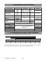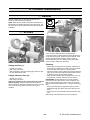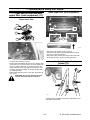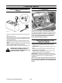
1
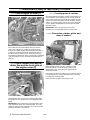
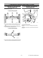
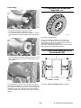
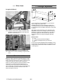
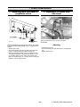
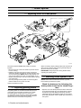
G. Maintenance schedule
G 1.
Service
Correct maintenance at the right time is a basic condition
for reliable operation of the tractor. Maintenance costs are
small compared with any repair costs resulting from lack
of maintenance. The most important measures are those
which you carry out yourself and which include lubrication
and various checks and adjustments.
The service intervals shown apply for normal operating
conditions but in more severe conditions servicing should
be carried out more frequently.
General instructions concerning oil checks and oil filling
G 1.1.
--- Always stop the engine before doing any servicing
work.
--- Apply the parking brake to ensure the tractor cannot
move. If the ground is uneven the wheels should be
blocked.
--- Always observe the utmost cleanliness in all maintenance work.
IMPORTANT: Do not let the water get to the electrical
equipment when washing the machine. Do not wash the
inside of the cab with a pressure washer.
--- Thoroughly wipe off filler caps and plugs as well as surrounding parts of the tractor before filling up with fuel or
oil.
--- Inspect the oil and filters when changing. Large amounts of dirt (e.g. heavily clogged filters) can point to a
fault which could cause extensive and costly repairs if
not corrected in time.
--- When carrying out checks the tractor should stand on
level ground.
--- Levels should be checked before driving when the oil is
cold and has had time to run down to the bottom of the
unit concerned.
--- When changing the oil, bear in mind that the oil can be
very hot when it drains from the tractor.
--- Avoid touching the exhaust manifold, turbocharger and
other hot parts of the engine.
--- Keep the engine surfaces clean in order to avoid the risk
of fire.
--- The fuel, lubricating oil and coolant cause irritation to
skin if in contact for long periods.
--- After completion of any service work replace all safety
covers etc.
--- Waste oil, liquid waste, oil filters and batteries should be
handled carefully and disposed of properly.
G 1.2.
Lubrication of points provided with grease nipples
--- Always clean the grease nipples before applying the
grease gun.
--- Pump in grease to the nipples until clean grease is
squeezed out (unless otherwise instructed).
--- Wipe off all surplus grease which has been squeezed
out at the lubricating points.
--- Preferably carry out lubrication with bearing points and
joints unloaded and with the bearings in different positions ( e.g. lubricate the steering knuckle bearing on the
steering axle with the wheels at both full left and right
lock and with the front axle lifted up).
G 1.3.
Lubrication and maintenance
schedule
NOTE: All intervals are counted from zero hours on the
hour recorder. For example, the 500 hours service is
carried out after 500, 1000 hours etc. even if the measures
have been carried out at the guarantee service (=100
hours service).
Example: The 1000 hour service contains all items
mentioned under the 10 h/daily and the 50 hrweekly
checks as well as the 500 h service.
G 1.4.
Service inspection (at 100 hours)
Your dealer gives this cost---free service inspection
(excluding oil and filter costs) after 100 hours running to
all new Valtra tractors.
The following steps should be taken:
20 Engine
--- Change engine oil and filter
--- Change prefilter of fuel system
--- Change fuel filter
40 Power transmission
--- Change filter
60 Steering system and front axle
--- Change oil in differential
--- Change oil in planetary gears
90 Hydraulic system
--- Change pressure filter and clean hydraulic pump suction strainer
General
--- Lubricate according to chart
--- Road test tractor. During the road test check all the
functions of all the controls and instruments. After the
road test, check for oil leaks, check the coolant and fuel
system.
---63---
G. Maintenance schedule
G 2.
Recommended fuel and lubricants
All volumes are with filters.
Part of machine
Engine
Valtra---grade
SAE/Viscocity
API---grade
Volume when
changing l
Valtra
Engine E
10W---30:
10W
30: ---20˚C...+30˚C
20˚C +30˚C
15W---40: ---10˚C
---10˚C...+40˚C
+40˚C
CG---4
CG
4 or
CH---4
9
Valtra
Transmission
Valtra
Hyrdraulic
Valtra
Transmission
HT 60: ---30˚C...+30˚C
HT 100: ---10˚C...+40˚C
32: ---30˚C...+30˚C
46: ---10˚C...+40˚C
HT 60: ---30˚C...+30˚C
HT 100: ---10˚C...+40˚C
A75n, A75L ---A95L
A85n
A95n
Hydraulic system
Power transmission
Powered front axle (4---WD)
(
)
differential
hubs
Front PTO
Fuel tank
--- with extra fuel tank
Cooling system
A75n, A75L
A85n
A95n
A85L, A95L
Brake fluid reservoir
Windscreen washer
G 2.1.
Valtra Axle
(Limited Slip)
Valtra Axle
Valtra
Engine
ISO VG 32
ISO VG 46
35 upper mark
(25 lower mark)
GL---4
32
GL---5
6,5
2x1
80W---90
10W/30
7
CE
CF/CF
GL 5/4
CCMC D4
14
1,4
70
95
The fuel (diesel) must conform to the EN 590 standard
standard.
13,5
A ti f
Anti---freeze
agentt + water
t (standardi
( t d di ASTM D3306---86a
D3306 86 or
BS 6580:1985)
15,5
15,5
10,0
0,3
1,5
Brake fluid SAE J1703
Washer fluid
Oil recommendations according to outdoor temperature
When starting the tractor in a warm garage, oil meant for warmer areas may be used.
HT 60 / H32
10W---30
15W---40 / HT100 / H46
80W---90
---30˚C
---20˚C
---10˚C
0˚C
+10˚C
+20˚C
+30˚C
+40˚C
69---81
ISO 15380 class HEES (synthetic esters) bio oils can be used as transmission and hydraulic oil. The oil must fulfil the
technical requirements of tractor transmission oil. The bio oil cannot be mixed with mineral oil.
G. Maintenance schedule
---64---
G 2.2.
Quality requirements of engine fuel
Property
Requirement
Test standard
Specific weight +15˚C, ISO 12185
0,82...0,86 kg/litre
ASTM D 4052, EN
mm2/s
Viscosity +40˚C, 445, ISO 31041
1,2...4,5
Sulphur content
max. 0,2 p---%
ASTM D 4294, ISO 8754
min. 51
ASTM D
max. 200 mg/kg
ASTM D 1744
max. 460 μm
ISO 12156---1
Cetane number 4737
Water content
Lubricity / HFRR
The fuel must conform to the EN 590 standard.
G 2.2.3.
IMPORTANT: To mix fuel with any admixing materials is not
allowed.
G 2.2.1.
Fuel
--- The properties of light fuel oil that is only intended for
warming use do not meet the requirements of modern
diesel engines and cannot be used as fuel.
--- In particular, distributor---type injector pumps require the
fuel to have sufficient lubricity, because they do not
have oil lubrication in the same way as typical multi---element pumps. Adding oil to diesel fuel is not recommended, because it causes carbon build---up, and if oil
is mixed with even a small amount of water it will clog
the filter.
--- Additionally, various fuel quality requirements imposed
by taxation and seasonal changes have to be taken into
consideration.
G 2.2.2.
ASTM D
Fuel storage
--- Storing and distributing fuel must be arranged in conditions where no water or impurities can enter the storage
tanks. The storage tanks must be installed in a slanted
position, so that water and impurities are collected at
the opposite end from the suction pipe of the pump.
The suction pipe of the pump should not reach the bottom of the tank.
--- Water must be periodically drained from the tank in
order to prevent problems. Refueling at the same time
the tank is being refilled must be avoided without exception.
--- When the tank is filled with winter---quality fuel in good
time, the engine is guaranteed to run flawlessly during
the cold season.
Filter system
--- The engine’s standard filter system gives sufficient
protection for the injection system from impurities that
can be present in well---tended distribution systems.
--- The control of distributor---type injection pumps is
based on internal pressure, which will drop if the fuel
system is clogged. If the pilot pressure drops too low,
engine power is reduced, smoke increased and starting
becomes more difficult. Additionally, water in the injection system will destroy it in a very short time. For this
reason, the water trap and the filters must always be
serviced according to the specified amount of running hours.
--- It is also important always to use original Valtra (or Sisu
Diesel) fuel filters. They guarantee sufficient filtration,
preventing impurities from damaging the fuel system.
There are many cheap filter kits (so---called pirates) on
the market, with lower quality and performance in order
to minimise the cost. Among other things, the quality
and amount of filter paper are often insufficient. There
are also often dangerous defects in the basic structure
that may cause expensive damage even in a short
period of time.
G 2.2.4.
Biodiesel fuel
The only possible alternative fuel to use is RME
(Rapeseed Methyl Ester) Biodiesel according to European
norm EN 14214 or US norm ASTM D6751. When using
Biodiesel the engine capacity is almost the same as using
diesel fuel.
---65---
G. Maintenance schedule
G 3.
Grease
universal grease for vehicle use. It is recommended for
greasing chassis, water pumps, pins etc.The grease is
adhesive, protects against corrosion and resists water and
varying temperatures.
Temperature range is ---25˚ ... +80˚C.
Always use the following greases in Valtra tractors. Each
point requires it own type of grease.
Valtra Grease, NLGI2
Universal grease
Lithium ---based universal grease. Is suitable for greasing all heavy machines.
---25˚ ... +130˚C
Universal grease of high quality, lithium based grease for
vehicle use. It is recommended for greasing wheel
bearings, chassis water pumps, catepillar rollers etc. The
grease is adhesive, protects against corrosion and resists
water and varying temperatures.
Temperature range is ---25˚ ... +130˚C.
Valtra Calsium LF, NLGI2
Calsium Grease LF
Is suitable for greasing all heavy machines. Long fibre
grease. Colour red. Especially good for greasing points
exposed to water.
---25˚ ... +80˚C
Valtra Grease Moly
Moly Grease
Is suitable for greasing all heavy machines. Lithium ---based universal grease. Molybdenum sulphide as an additive (1---3%) improves greasing in places exposed to
shock loads.
---25˚ ... +130˚C
Universal grease of high quality, lithium based grease for
vehicle use. It is recommended for greasing wheel
bearings, chassis water pumps, catepillar rollers etc. The
grease is adhesive, protects against corrosion and resists
water and varying temperatures.
Temperature range is ---25˚ ... +130˚C.
Avoid repeating skin contact.
Protect nature and take care of empty packages.
Calsium LF is of long fibre, high quality and calsium based
G 4.
Maintenance schedule
PERIODICAL MAINTENANCE---schedule (according to
operator’s manual) is recommended for all tractors and
specially for tractors, which have more than 1000 running
hours in one year. The periodical maintenances from 50
hours onwards can also be ordered from the authorized
workshop. In that case the periodical maintenance is
carried out by Valtra authorized and trained service
personnel.
Observe when doing the services that if the tractor is
equipped with extra equipment like towing device, air
condition, air pressure brakes etc. the periodical
maintenances and checks for them must be carried out.
The extra equipment which needs servicing is given in the
end of this manual in section ”K”.
YEARLY MAINTENANCE---schedule should be carried
out by an authorized workshop, but for tractors which
have under 1000 running hours in one year the operator
has to carry out the normal service routines according to
the following table (like daily and weekly periodic
maintenance).
G. Maintenance schedule
---66---
The same numbering system as used on the detached
maintenance schedule are placed in brackets where
applicable.
G 4.1.
G 4.3.
See page
11. Clean cab air filter and also upper filter (extra
equipment)
75
12. Lubricate gear lever joints
75
13. Check wheel nuts tightness
76
14. Check brake fluid level
76
15. Grease door hinges
76
16. Change engine oil and filter (or yearly), in extremely
dusty conditions or when using over 5 % Biodiesel
fuel at 250---hour.
77
17. Check brake pedal free travel
77
18. Check clutch pedal free travel
78
19. Check PTO lever free travel
78
20. Check oil level in power/ transmission
78
21. Check oil level in differential, 4---wheel drive
78
22. Check oil lever in hub reduction gears,
4---wheel drive
79
23. Check oil level in hydraulic system
79
24. Change pressure filter in hydraulic system
79
25. Change oil filter transmission
79
Daily/every 10 hours
See page
Check engine oil level
70
Check coolant level and radiator fins and front grilles
of the engine cover
70
1.
2.
G 4.2.
Weekly/every 50 hours
3.
Lubricate front axle and steering nipples
2---wheel drive
--- front axle mountings (2 nipples)
--- steering knuckles (2 nipples)
4---wheel drive
--- front axle mountings (2 nipples)
4. Lubricate brake and clutch pedals (3 nipples)
5. Lubricate top link and lifting links
6. Check fluid level in windscreen washer
7. Check belts tightness
8. Check electrolyte level in battery
9. Check prefilter and fuel filter of fuel system
10. Check tyre pressures
5
10
13
25
4
18
19
71
71
72
72
72
73
74
74
14
Every 500 hours
NOTE: When carrying out servicing you must follow
the service intervals, i.e., you must also do all previously mentioned items. For example, when doing
500 hours service you must also do the servicing required weekly and daily.
6
9
16
1
16
22 21
10
13
3
13
3
10
23
20
5
7
5
10
13
12
24
4
17
11
8
11
2
10
13
21
22
---67---
2
3
13
3
10
A G1
G. Maintenance schedule
G 4.4.
38. Tighten bolts and nuts of frame
39. Grease flywheel ring gear
Every 1000 hours/yearly
See page
26. Change oil and oil breather filter of the hydraulic
system
80
27. Change oil in power transmission
80
28. Change oil in differential, 4---wheel drive
81
29. Change oil in hub reduction gears, 4---wheel drive 81
30. Clean hydraulic pump suction strainer
81
31. Clean fuel tank
82
32. Change prefilter and fuel filter of fuel system, when
using over 5 % Biodiesel fuel at 500---hour
82
33. Change air filter and safety filter
82
34. Lubricate front wheel bearings, 2---wheel drive
83
35. Check and adjust toe---in of front wheels
83
36. Adjust valves
84
37. Change cab air filter and upper filter (extra equipment)
84
27
42
G 4.5.
84
84
Every 2000 hours/every other
year
40. Clean coolant system
41. Check and clean injectors
42. Change brake fluid
85
86
86
NOTE: When carrying out servicing you must follow
the service intervals, i.e., you must also do all previously mentioned items. For example, when doing
2000 hours service you must also do the servicing required at 1000, 500, weekly and daily.
39
32
40
35
29
40
28
33
34
35
26
27
27
31
37
40
A G2
G. Maintenance schedule
---68---
36
41
30
35
29
28
34
35
H. Periodic maintenance
H 1.
General
Periodic maintenance for the extra equipment are in
section K, after each extra equipment.
A
NOTE: When the tool symbol of periodic maintenance is
illuminated in the display (Agroline instrument panel), the
service work has to be carried out before the tool symbol
is deleted.
1
H 1.1.
Air filters
1
A H12
2
A H11
A low---pressure indicator with a warning lamp is
connected to the air cleaner. When the lamp (A) lights up
on the instrument panel, the filter must be cleaned. If the
warning light illuminates quickly in dusty conditions,
check the ejector pipe (1) is fitted properly, the models
A75n and A75L---A95L have dustvalve.
Cleaning:
Change air filter (1):
--- At least once a year
--- After every 1000 hours
--- After 5 cleanings, when the warning light of the air cleaner has illuminated 5 times
Change safety air filter (2):
--- At least once a year
--- After every 1000 hours
Unless it is necessarry do not open the cover of the air
cleaner housing. Only associated with the situations
mentioned before. During the maintenance check, that the
cover of the housing, pipes and unions are in good
condition.
--- Always stop the engine before cleaning. A blockage of
the air filter is indicated by a change of the engine beat,
smoky exhaust and reduction of engine power.
--- Check the inside of the air cleaner housing and the inlet
pipe. Dirt on these parts indicates that the filter element
is defective or has not been fitted properly.
--- Clean the filter element with compressed air, max. pressure 500 kPa, or with an effective vacuum cleaner.
IMPORTANT: The filter element must not be cleaned
more than 5 times, after which it must be replaced. The
filter must be changed every 1000 hours in accordance
with the maintenance requirement:--- change of the safety
filter.
--- Hold up the filter element against the light (or shine a
flashlight through the centre hole) and inspect the element.
--- If any holes are noticed the filter element must be changed.
Filters fitting, see maintenance point 33 on page 82.
---69---
H. Periodic maintenance
H 2.
H 2.1.
Maintenance daily at least every 10 hours
Check engine oil level (1)
H 2.2.1.
Freezing point of coolant
Check the freezing point of the coolant at the beginning of
the cold season. If the freezing point is too high, drain off
some of the coolant and top up with anti---freeze. Run the
engine for a while until the anti---freeze has been mixed in,
then re---check the freezing point of the coolant. Drain the
cooling system completely every second year and refill
with new coolant.
2
IMPORTANT: Never use just water as a coolant.
Ensure that a recommended coolant is always used.
1
H 2.2.2.
Check also radiator grilles and
clean if needed
A H13
The oil lever should come between the max. and min.
marks on the dipstick (1). Adding oil should be done
through the oil filler cap (2). Stop the engine and allow it
to stand for a few minutes before checking the level so
that all the oil has had time to run down into the sump.
The distance between the marks corresponds to 1.5 liters
of oil. Oil quality is to be in accordance with the table on
page 64.
Check coolant level and radiator fins and the front grille of
the engine cover (2)
H 2.2.
A H17
When cleaning use air pressure, a water hose (not
pressure washer) or a soft brush (be careful not to
damage the cores). Direct the spray against the air
streaming direction.
1
If the tractor has the air conditioning, its condenser can be
moved sideways (by opening the locking nut on the left)
for making the cleaning easier.
Clean also the front grille of the engine cover.
2
A H16
The expansion tank (1) has a liquid level sign (2) where
the liquid level must be when it is cold. Hot liquid level is
higher.
IMPORTANT: The coolant pump is provided with a drain
hole underneath which must not be blocked. On a new
engine a certain amount of leakage can occur before the
pump has had time to run itself in.
H. Periodic maintenance
---70---
H 3.
H 3.1.
Maintenance weekly at least every 50 hours
Lubricate the front axle and
steering nipples (3)
H 3.2.
Lubricate the brake and
clutch pedals (4)
Use Valtra Universal Grease.
2---wheel drive models
B
B
A
A
65---89
A3565---87
A. Front axle mountings: Lubricate the nipples (two) with
grease (lift up the front end to take the weight off the
axle).
B. Steering knuckles: Turn the steering wheel backwards
and forwards when lubricating (2 pcs).
4---wheel drive models
Use Valtra Universal Grease.
One nipple on left side for lubricating the clutch pedal
bearing.
Two nipples on right side for lubricating the brake pedal
bearings.
A
A
A3565---88,1
A. Front axle mountings: Lubricate the nipples with grease
(lift the front end to take the weight off the axle), 2 pcs.
---71---
H. Periodic maintenance
wiper , it has its own container in the rear of the tractor.
Lubrication of the three--point linkage (5)
H 3.3.
H 3.5.
Check belts tensions (7)
The belts are suitably tensioned when they can be
pressed in about 10 mm (0.79 in) with the thumb halfway
between the belt pulleys.
Check that the fan belts are in good condition when
adjusting. Slack, worn and/or oily fan belts can cause
problems with battery charging and the cooling system.
Always keep spare fan belts handy.
1
3
1
H 3.5.1.
Alternator belt
2
2
3
4
4
65---61
Use Valtra Universal Grease.
--- 1, the top link, 2 pcs
--- 2, lifting links 2 pcs
--- 3, extra cylinder 2 pcs
--- 4, telescopic lower links 2 pcs (additional equipment)
H 3.4.
A H41
The alternator belt adjustment is done by turning the
alternator in its fasteners. Remove the finger shield if
necessary.
Check fluid level in windscreen washer (6)
H 3.5.2.
Water pump/coolant fan belt
B
A
A H42
A H14
Check that there is always sufficient fluid in the container.
Add washer fluid to the water. In winter use anti---freeze
washer fluid. If the tractor is equipped with a rear window
H. Periodic maintenance
Tensioning belt
--- Loosen the fastening of the adjustment belt pulley (A)
---72---
--- Adjust through the adjusting rod (B) of the adjustment
belt pulley
--- Tighten the adjustment belt pulley
H 3.5.3.
Air conditioning compressor
belt (extra equipment)
1
1
2
A
A
A H46
In open cab models when changing the belt loosen the
Visco--- fan (1) from the belt pulley by unscrewing the
nut (2).The belt can be changed without detaching the
fan.
A
A H43
The adjustment is done by turning the compressor (1) in
its fasteners. All the three attaching bolts (A) have to be
slackened when doing the adjustment.
H 3.5.4.
IMPORTANT: The nut is left hand thread.
H 3.6.
Check electrolyte level in battery (8)
Air pressure compressor belt
(extra equipment)
A
B
A H18
Electrolyte level
A H44
The pressure air compressor belt tension is adjusted with
the adjustment belt pulley (A) by slackening the belt
pulley nut (B).
H 3.5.5.
Changing the belts
The fan has to be released from the belt pulley by opening
the mounting bolts forward of the fan before changing the
belt/belts (not alternator belt).
--- The battery electrolyte level should be on the level
marked on the battery. If the battery has not that mark
check that the electrolyte level is approx. 5---10 mm
(0.2---0.4 in) above the cell plates in the battery.
--- Top up with distilled water if necessary.
--- Never top up the battery with acid only and never use a
naked flame when checking the electrolyte level.
NOTE: If the water in the battery evaporates too quickly, it
may be a sign that the charging voltage is too high. Keep
the outside of the battery clean and dry. Protect the
battery and cable terminals with special grease.
---73---
H. Periodic maintenance
IMPORTANT: In winter it is very important to allow the
engine to run for a little while after topping up with distilled
water, otherwise the water can freeze before it has mixed
properly with the battery acid.
WARNING: Be carefully with the battery
solution ---danger from corrosion!
H 3.7.
H 3.8.
Check tyre pressures (10)
NOTE: Check tyre pressures frequently (values are listed
in the Technical Specifications on page 102).
DANGER: Avoid over inflation as excess
pressure may cause the tyre to explode.
Check prefilter and fuel filter (9)
It is recommended that the changing of tyres and wheels
is carried out in a professional tyre workshop which is
equiped to handle this type of work.
DANGER: When welding the discs the tyre
must be away from the rim/ disc, DANGER
OF EXPLOSION!
2
When mounting the tyre on the disc the pressure limit is
250 kPa. If the tyre does not go on the disc properly,
remove it and refit. When the tyre is positioned correctly
on the disc, inflate to correct pressure.
1
3
A H19
Drain the prefilter by opening the tap (1) a little in the
bottom of the prefilter. By opening the airscrew (2) in the
upper part of the prefilter water comes out easier. After
draining water close the tap and the airscrew.
Drain the prefilter more often to reguired.
Drain water from the fuel filter by opening the tap (3) in the
bottom of the filter. Close the tap.
Drain the fuel filter more often if reguired.
Bleed the fuel system if necessary, (see “Checks and
Adjustments on page 88).
H. Periodic maintenance
---74---
H 4.
Maintenance every 500 hours
Clean upper filter (extra equipment)
Clean cab air filter and also
upper filter (extra equipment) (11)
H 4.1.
Clean lower filter
1
1
2
3
2
3
3
A H47
1
--- Remove the air cleaner housing cover (1).
--- Pull the mounting links (3) of the filter element (2) up
and turn to the arrow direction
--- Remove the filter element and clean as the lower filter
--- Fit the filter element, the arrow pointing upwards
A H40
H 4.2.
--- Lift up the filter housing cover (1)
--- Remove the filter element (2) and knock it with the palm
of the hand, use a vacuum cleaner from the direction air
goes in or blow it clean with compressed air from the
centre outwards. Make sure that the air pressure is not
too high. Check the condition of the filter. Always change a damaged filter.
--- Refit the filter element. Fit the cover right, the guides (3)
face to face.
WARNING: The air filter element does not
remove chemicals from the outside air.
Lubricate gear lever
joints (12)
A H21
Carefully clean joint before lubricating. Lubricate the joint
with Valtra Grease Moly.
---75---
H. Periodic maintenance
H 4.3.
Check wheel nuts (13)
NOTE: Check torque of wheel nuts (also rim/wheel discs)
frequently (values are listed in the Technical Specifications
on page 101).
H 4.4.
Check brake fluid level (14)
A H28
Add fluid until the level is between the min. and max.
marks.
WARNING: Brake fluid is corrosive and
poisonous and must be handled carefully at
all times (it also corrodes the paint).
H 4.5.
Grease door hinges (15)
A H22
There are nipples on door hinges. Use Valtra Universal
Grease.
The fluid level should be between the max. and min.
marks. Top up with new fluid as necessary, see
recommended fuel and lubricants on page 64.
WARNING: Normally there will be no need
to top up the fluid. If leakage has occurred,
it must be repaired immediately, before
driving. If necessary, contact the authorized
Valtra---workshop.
The brake fluid level should be checked frequently. Use
recommended fluid only.
2
1
A H27
If the tractor is equipped with the push buttons for HiShift
as extra equipment, check the brake fluid level through
the hole of the shield (1). If brake fluid has to be added,
loosen the shield (2).
H. Periodic maintenance
---76---
H 4.6.
Change engine oil and engine
oilfilter (16)
In extremely dusty conditions or when using over 5 %
Biodiesel fuel, the oil and filters should be changed every
250 hours.
If the amount of operating hours is low, the oil and filters
should be changed at least once per year.
H 4.6.1.
Draining
H 4.6.4.
Filling
Oil quality is to be in accordance with the table on
page 64.
Fill up with new oil to the prescribed level (upper mark on
dipstick 3) through the filler opening (2).
Oil volume incl. filter
---A75n, A75L---A95L . . . . . . . . . . . . . . . . . . . . . . . . . . . . . . 7 l
---A85n, A95n . . . . . . . . . . . . . . . . . . . . . . . . . . . . . . . . . . . . 9 l
Filter capacity 0.5 I.
The distance between max and min marks on the dipstick
corresponds to 1.5 liters of oil.
Then start the engine in the normal way. Allow the engine
to idle for a little while and check the oil level again.
H 4.7.
Check free travel of brake pedals (17)
60 mm
65---68
Remove the drain plug and allow the oil to run out into a
suitable container. Drain the oil while the engine is warm
(makes draining quicker particularly in cold weather).
Clean the plug and replace it.
H 4.6.2.
Changing oil filter
A3565---102,1
The free travel should be 60 mm (2.4 in) when the pedals
are connected together. Adjust the free travel if necessary
(see under ” Checks and adjustments” on page 94).
2
H 4.7.1.
Adjusting parking brake
3
1
A H23
--- Remove the oil filter (1) by unscrewing it
--- Wipe off the oil which has run out on the chassis
--- Oil the new gasket
--- Tighten the new filter by hand (not too hard).
H 4.6.3.
Crankcase ventilation
65---73
The parking brake acts on the foot brake mechanism
mechanically by means of a rod.
Adjust the free travel if necessary (see under ” Checks
and Adjustments” on page 94).
When changing the oil always check that the ventilation
pipe is clean and not blocked.
---77---
H. Periodic maintenance
H 4.8.
Check pedal free travel of
propulsion clutch (18)
H 4.10.
Check oil level in power
transmission (20)
20---25 mm
65---75
A3565---104
Slowly press down the clutch pedal until the clearance is
taken up and declutching begins. The free travel should
be 20---25 mm. Adjust the free travel if necessary (see
under ”Checks and Adjustments” on page 93).
H 4.9.
Check the travel of PTO lever (19)
The oil level should come between the max. and min.
marks on the dipstick. Top up with oil when necessary. Oil
quality should be in accordance with the table on
page 64.
The distance between max and min marks on the dipstick
corresponds 3 liters of oil.
H 4.11.
Check oil level in differential
4---wheel drive (21)
A3565---107
69---74
The free travel at the end of the lever should be 30---40
mm. Adjust the free travel when necessary (see under
”Checks and Adjustments” on page 93).
H. Periodic maintenance
The oil lever should come up to the filling plug hole. Top
up when necessary.
Oil quality should be in accordance with the table on
page 64.
---78---
Check oil level in hub reduction gears, 4---wheel drive (22)
H 4.12.
H 4.14.
Change pressure filter in hydraulic system (24)
A3565---100
A3565---108
Turn the wheel until the oil surface indicator line is
horizontal. The oil surface should be level with the hole.
Add more oil if necessary. Oil quality should be in
accordance with the table on page 64.
H 4.13.
Check hydraulic oil level (23)
--- Clean surrounding parts
--- Loosen the filter and take out the element
--- Wash the filter housing with diesel fuel and fit the new
element (oil the seal first). The seal must always be
changed.
--- Tighten the filter with a suitable wrench to a torque of
200 Nm.
IMPORTANT: Always change the filter when carrying out
repairs caused by impurities in the hydraulic system.
Clean suction strainer as described earlier (see service at
1000 hours intervals page 81).
IMPORTANT: If the external hydraulics are used
extensively and no return oil filter is used, the filter must
be changed ever 250 hours.
If the external hydraulics are used extensively it is
recommended that a return filter should be mounted in
the line (extra equipment).
On tractors with a return filter, all oil which is returning
from the outside machine, goes through the return filter.
Follow to changing intermediate on the return filter.
H 4.15.
Change oil filter in transmission (25)
69---76
When the hydraulic system is filled to the minimum mark
on the dipstick the total volume of oil is 25 l, of which 14 l
is available for the auxiliary hydraulics.
It is, however, recommended that the system be filled to
the maximum mark on the dipstick (total volume =35 l). In
this case 24 l is available for the auxiliary hydraulics.
Adding oil, see point 26 change oil in hydraulic system.
Oil quality should be in accordance with the table on
page 64.
65---77
--- Clean surrounding parts and remove the filter
--- Oil a new seal and fit the new filter. Tighten by hand (not
too tight).
---79---
H. Periodic maintenance
H 5.
Maintenance every 1000 hours or yearly
Where the larger quantity is recommended, 35 l, the oil
level should come up to the upper mark on the
dipstick which is fitted on the oil filler cap. Then 24 l
can be taken out for auxiliary hydraulics.
Change oil and oil breather
filter in hydraulic system (26)
H 5.1.
Draining
H 5.2.
Change oil in power transmission (27)
Draining
65---78
--- Run the tractor for warm up the hydraulic oil.
--- Remove the drain plug and drain off the oil
--- Clean the plug and replace it in again
Refilling
A3565---112,1
--- Run the tractor to warm up the transmission oil.
--- Remove the plugs under the gearbox and final drive
gears and allow the oil to run out into a suitable container.
--- Clean the plugs and screw them in again.
2
3
4
Filling
1
69---79,1
--- For refilling the oil, first open the breather filter (2) together with the fastening tube (3) by opening the locking
nut (4) (hole inside the breathers fastening tube is too
small for refilling the oil).
--- Refill with new oil through the filling cap. The lower mark
on the dipstick (1) corresponds to 25 l, the upper mark
to 35 l. The system may be filled to any level between
these two points.
--- Subsequent to refilling, the engine should be started
and the hydraulic lift operated for a short time, after
which the level should be checked again. Replace the
breather filter (2) and adjust it with fastening tube (3) so
that the filter top is horizontal.
H. Periodic maintenance
65---75
Oil quality should be in accordance with the table on
page 64.
--- Remove the plug on the dipstick opening
--- Fill up with new oil to the upper mark on the dipstick.
Oil quantity is 32 l. The distance between max and min
marks on the dipstick corresponds to 3 liters of oil.
---80---
H 5.3.
Change oil in differential,
4---wheel drive (28)
H 5.5.
Clean hydraulic pump suction
strainer (30)
3
1
2
A H24
A3565---114
Remove the drain plug (1). Clean the plug and screw it in
again. Fill up with new oil through the filling opening (3) to
the lower edge of the level plug (2).
Oil volume 6.5 l
Oil quality should be in accordance with the table on
page 64.
IMPORTANT: In work where the hydraulic system is
subjected to abnormally heavy pollution (e.g. when
running with tipping trailers) the suction strainer must be
cleaned at shorter intervals. If the pump begins to
”shriek”, the engine should be stopped, the suction
strainer cleaned and the viscosity of the oil checked
against the manufacturer’s recommendations.
H 5.5.1.
Change oil in hub reduction
gears, 4---wheel drive (29)
H 5.4.
Removing and cleaning
--- Place the tractor with the front end higher so that less oil
runs out.
--- Loosen the wing nut on the end of the housing and place a funnel or similar under the housing to collect up the
oil.
--- Remove the cover and drain off the oil into a suitable
container.
--- Carefully pull out the element.
--- Clean the element with diesel fuel and dry with compressed air.
--- Also clean the magnetic plugs.
H 5.5.2.
Fitting
--- Place the cleaned element in the housing
--- Replace the cover together with the seal and tighten the
wing nut by hand
--- Check the oil level in the hydraulic system.
IMPORTANT: Look for any foaming of the oil when
starting up again (check through the filling opening).
Foaming indicates that the cover seal is leaking and must
be changed or retightened.
A3565---108
Unscrew the plug and drain the oil. Turn the wheel until
the line of the inspection hole is horizontal and fill up with
oil to the level of the hole.
Oil volume 2 x 1 l
Oil quality should be in accordance with the table on
page 64.
---81---
H. Periodic maintenance
H 5.6.
Change fuel filter
Clean fuel tank (31)
Always clean the fuel tank at the start of the winter
season. This avoids problems with condensation in the
fuel tank. Always make sure that the tank is as full as
possible so that condensation is prevented.
--- Empty the tank and rinse it with clean diesel fuel. Screw
in the drain plug again.
--- Fill up with new fuel (if you suspect that fuel is not clean,
use a fine gauze strainer).
IMPORTANT: Never use spirit as anti---freeze agent in the
fuel, as this could cause blockage of the fuel filter and
impair the lubricating properties of the fuel.
H 5.7.
1
2
Change prefilter and fuel filter (32)
When using over 5 % Biodiesel the changing is every 500
hours.
A H26
IMPORTANT: Remove the filter by hand, do not use a
filter---wrench.
--- Turn the prefilter lock (1) to open and remove prefilter (2).
--- Set new filter in place. NOTE: The filter can be set in
place only in one position.
--- Turn the prefilter lock in direction (ON) until you hear a
click.
IMPORTANT: If needed change the filters more often.
Change prefilter
3
5
After changing the filters bleed the fuel system (see under
”Checks and Adjustments” on page 88).
1
4
H 5.8.
2
Change air filter and safety
filter (33)
A H25
IMPORTANT: Remove the filter by hand, do not use a
filter---wrench.
--- Slightly open the drain cock (2) at the lower part of the
prefilter (1) and drain the fuel into a container, NOT ON
THE GROUND.
--- If the bleeder---screw is opened (3) in the prefilter’s mounting frame, the fuel drains more easily. After draining
has been completed, close the bleeder---screw.
--- Unfasten the water trap (4) from the prefilter.
--- Turn the prefilter lock (5) to open and remove prefilter (1).
--- Set new filter in place. NOTE: The filter can be set in
place only in one position.
--- Turn the prefilter lock in direction (ON), until you hear a
click.
--- Fasten the water trap to the lower part of the prefilter.
2
1
A H29
The main air filter (2) has to be changed no later than
1000 hours together with the safety filter (1) if it has not
been cleaned already 5 times and changed earlier.
The safety filter protects the engine if the main filter should
become damaged. The safety filter must not be cleaned, it
should always be changed.
IMPORTANT: Never run the tractor without the safety filter.
Take great care when removing the safety filter so that no
dirt enters the inlet pipe.
--- Take out the main filter (2)
--- Remove the safety filter (1)
H. Periodic maintenance
---82---
Filters fitting
H 5.9.
Lubricate front wheel bearings (34) (2WD)
3
1
A H30
--- Check that, the seals are in good condition
--- Check that, the sealing surfaces are clean
--- Fit a new safety filter (1) and make sure that it is correctly positioned in the housing. Tighten the nut (3) carefully.
3565---117,1
Use Valtra Universal Grease.
In dusty and muddy conditions, it is necessary for
lubrication to be carried out much more often. When
injecting new greese, ensure that enough is injected so
that it pushes the dirt out of the hub.
Check also the bearings tightness and if necessary have
them adjusted at an authorized workshop.
4
H 5.10.
2
Check and adjust toe---in of
front wheels (35)
A H31
A
--- Fit the main filter (2) carefully. Tighten the nut (4), on the
filter until the filter has come into contact with the end of
the housing.
5
A+ 2...6 mm
6
(4---WD:A+0...2 mm)
3565---118
A H32
Do not tighten the nut (5) on the cover of the air cleaner
housing too tight (approx 1---1.5 turns after the flange seal
has come into contact with the surface of the housing). On
models A75n and A75L---A95L the cover of the housing
must be mounted so that the outlet pipe (6) is in the lower
position.
See under ”Checks and Adjustments” on page 95.
---83---
H. Periodic maintenance
H 5.11.
Change upper filter (extra equipment)
Check and adjust valve clearance (36)
1
2
3
A3565---120
A H47
Both inlet and exhaust valves should have a valve
clearance of 0.35 mm (0.014 in). The valve clearance can
be adjusted when the engine is either warm or cold.
Checking and adjustment should be carried out by an
authorized workshop.
H 5.12.
--- Remove the air cleaner housing cover (1).
--- Pull the mounting links (3) of the filter element (2) up
and turn to the arrow direction
--- Remove the filter element and replace the filter with a
new one
--- Fit the filter element, the arrow pointing upwards
Change cab air filter and upper filter (extra equipment) (37)
H 5.13.
Tighten frame nuts and
bolts (38)
Change lower filter
H 5.14.
1
Grease flywheel ring gear (39)
3
2
3
1
A H33
A H40
Lift up the filter housing cover (1) and replace the filter (2)
with a new one (fit the cover correctly, the guides (3) face
to face). Change filter more often if necessary.
H. Periodic maintenance
Remove first the shield. On the left---hand side of the
clutch housing there is a hole (remove the shield plug)
through which the ring gear can be greased. Apply a little
grease (one stroke with a grease gun) at a few points on
the ring gear. With use the grease will spread round the
gear. Use Valtra Moly Grease, about 1 cm3.
---84---
H 6.
H 6.1.
Maintenance every 2000 hours or every other year
Clean coolant system (40)
Periodically check and clean the outside of the radiator by
means of compressed air or by flushing through with
water. Also clean from the fan side of the radiator.
The cooling system can be thoroughly cleaned if
problems occur in the function, in which case clean as
follows.
Clean the coolant system using a special cleaning agent
available from your dealer. Follow the manufacturer’s
instructions.
H 6.1.1.
Draining
3
Always stop the engine before draining the coolant.
A H36
1
--- Open the tap (3) on the cylinder block
--- Turn on the heater control in cab. Drain the fluid into a
container.
--- Drain the water pump by cranking the engine a few revs
with the drain plugs removed.
H 6.1.2.
Filling
Mix the antifreeze and water according to the
manufacturer’s instructions.
Before filling:
A H34
--- Fasten the radiator lower hose (2)
---Close the drain plug of the cylinder group (3)
--- ALWAYS open the cap (1) of the expansion tank first.
carefully. At running temperature the expansion tank
has overpressure (1.0 bar).
4
2
A H35
--- Loosen the lower water pipe (2) (remove the finger shield if necessary). The best way to drain the system is to
loosen the upper end of the pipe and then loosen the
lower end, then the pipe can be bent to the side and the
fluid drained into a container.
A H37
--- Loosen the hose placed on the thermostat housing
going to the expansion tank and check that the restrictor hole (Ø about 2 mm) in the union (4) is open. Refasten the hose.
---85---
H. Periodic maintenance
Symptoms of dirty or defective injectors:
--- Knocking indicates a fault on one or more of the injectors. Knocking can occur on a cold engine when running at idling speed. When knocking occurs at normal
working temperature this indicates that the injectors are
not functioning property.
--- Air in the fuel system can also cause knocking (disappears after the system has been bled).
--- Smokey exhaust gases are another symptom of poor
function of the injectors (can also be due to other reasons, e.g. blocked air cleaner).
5
H 6.3.
Change brake fluid (42)
A H38
--- Fill the system to the expansion tank fluid level mark (5).
H 6.1.3.
Coolant volume
--- A75n, A75L . . . . . . . . . . . . . . . . . . . . . . . . . . . . . . . . . . 13.5 l
--- A85n . . . . . . . . . . . . . . . . . . . . . . . . . . . . . . . . . . . . . . . 15.5 l
--- A95n . . . . . . . . . . . . . . . . . . . . . . . . . . . . . . . . . . . . . . . 15.5 l
--- A85n, A95L . . . . . . . . . . . . . . . . . . . . . . . . . . . . . . . . . . 10,0 l
Ensure that a recommended coolant is always used.
IMPORTANT: Never fill up with cold fluid while the engine
is warm. Do not use plain water as coolant.
After changing the fluid run the engine for a time and
check the level of fluid.
H 6.2.
Check and clean injectors (41)
A H22
WARNING: Brake fluid is corrosive and
poisonous and must be handled carefully at
all times (it also corrodes the paint).
A3565---123
For the engine to produce full power the injectors must be
in perfect condition. Checking and cleaning should be
carried out by an authorized workshop.
H. Periodic maintenance
It is recommended that the brake fluid be changed every
second year or after 2000 hours of operation.
--- Empty the brake fluid reservoir, open the bleed nipples.
It is better to place hoses from the nipples into a container, as the fluid corrodes the paint. Pump the brake
pedal until all brake fluid in the pipes and cylinders has
run out.
--- Fill the brake system with new brake fluid.
--- Bleed the brake system of air (see Checks and Adjustments on page 94).
If the tractor is equipped with the trailer brake valve and /
or air pressure brakes as extra equipment, open also their
bleed nipples to drain the hoses. The brakes must also be
bleeded from the nipples:
--- the fluid brakes of the trailer, see the bleeding instructions on page 122.
--- the air pressure brakes, see the bleeding instructions on
page 120.
The correct amount of brake fluid is 0.3 liter.
---86---
A H39
If the tractor is equipped with the push buttons for HiShift
as extra equipment, change the clutch fluid. The clutch
fluid reservoir for HiShift is to the left side of the battery
(the shield has to be loosened). Empty the clutch fluid
reservoir (loosen first the service cover from the
mudguards) by loosening the hose coming from the
reservoir from the valve side.
The correct amount of clutch fluid is 0.3 liter.
---87---
H. Periodic maintenance
I. Checks and Adjustments
Check and adjustment instructions for the extra
equipment are in section K, after each extra equipment.
Engine
I 1.
I 1.1.
Bleeding fuel system
There should be no air in the fuel system to ensure that
the motor function is of maximum efficiency. The system
automaticly removes the small guantity of air which has
built up in the filters and injection pump. The fuel system
must be bled if any part of it has been removed or if the
tractor has run out of fuel during driving so that air has
entered the system. Bleed the fuel system as follows:
2
A I6
2. Start the engine to the low idling, do not race. If the
engine does not start, open the union (2) of the bleeding pipe from the fuel filter to the injectors. Pump by
hand pump, until the fuel is running out from the union.
Tighten the union and dry the fuel overflowed.
IMPORTANT: Do not open the union in the upper part
of the prefilter, because it is on the suction side.
3. Start the engine and check that there are no leaks.
1
I 1.2.
A I5
Air cleaner
1. Pump by hand the lever (1) on the fuel pump. If pumping feels ineffective, turn the engine a little, so the
camshaft turns away from the line of the pump arm.
A I7
The air cleaner prevents dust and other dirt from entering
the engine with the induction air. Engine wear is largely
dependent on the cleanliness of the induction air so it is
very important to check the air cleaner regularly and to
I. Checks and adjustments
---88---
maintain it correctly.
IMPORTANT: The safety filter inside the main filter must
not be cleaned but must always be changed according to
the maintenance schedule. The purpose of the safety filter
is to prevent damage to the engine if the main filter should
fail.
I 1.2.1.
IMPORTANT: See service instructions on page 69 and
replace safety filter in the air cleaner (maintenance every
1000 hours or yearly page 82).
I 1.3.
Maintenance---cooling system
Maintenance of main filter
A3565---129
A3565---127
The air filter must not be cleaned more than five times,
after which time it must be replaced. Check when cleaning
that the filter and its seals are undamaged. A damaged
filter must always be replaced.
IMPORTANT: Never clean or remove the air filter unless it
is absolutely necessary. When removing the air filter there
is always the possibility that dirt can enter the induction
system of the engine.
The following action should be taken to make sure that
the cooling system functions correctly:
--- Check the coolant level (see maintenance program daily
checks).
--- Check the fan belt tension (see maintenance program
weekly checks).
--- Clean the radiator honeycomb externally by means of
compressed air or by flushing through with water.
Cleaning the main filter
I 1.3.1.
Coolant
The cooling system is filled with a mixture of water and
anti---freeze agent on delivery. The anti---freeze agent also
has the property of preventing rust from forming in the
cooling system. However, the anti---rust properties of the
agent diminish with time so that it is important to change
the coolant at regular intervals. A suitable mixture is half
anti---freeze agent and half water but the manufacturer’s
directions should always be followed (see cleaning of
cooling system, Service at 2000 hrs intervals on page 85).
A3565---128
Use clean and dry compressed air with a max. pressure of
500 kPa (5 bar).
1. Direct the air flow against the inside of the filter along
the folds. Do not hold the nozzle closer than 3---5 cm.
2. Then direct the air flow against the outside of the filter
along the folds and after this against the inside of the
filter again.
3. Check the filter and its sealing surfaces by means of a
torch. Replace the filter if any holes or other defects are
discovered.
---89---
I. Checks and adjustments
I 2.
I 2.1.
Electrical system
Checking and maintenance of
battery
I 2.2.
Alternator
A I8
A3565---130
--- Check the charge of the battery with an acid tester. Min.
1.23.
--- Check fan belt tension.
--- Keep the battery clean. It can be washed with lukewarm
water after removal from the tractor (always disconnect
the negative lead first).
--- Also clean the pole studs, the cable terminals and the
battery retainer thoroughly. Wash off oxidized spots with
water.
--- Wipe the outside of the battery, and coat the pole studs
and the cable terminals with petroleum jelly.
--- Refit the battery (always connect the positive lead first).
DANGER: Avoid sparking or naked flames
near the battery. The battery gives off
hydrogen gas which is highly explosive. The
battery electrolyte is corrosive.
The tractor has a negative---grounded alternator which
can easily be damaged if an incorrect connection is made
in the electrical system. For example, connection of the
battery with wrong polarity can burn out the alternator or
rectifier. The electrical charging circuit must not be
broken when the engine is running.
I 2.3.
Safety precautions for the
electrical system
--- Always connect the battery with the correct polarity.
--- Disconnect the negative lead of the battery first and
connect it last.
---Never brake the charging circuit while the engine is running.
--- Disconnect the battery negative lead before removing
the alternator from the engine.
--- Arrange enough ventilation to prevent the build---up of
explosive gases in and around the battery.
IMPORTANT: The battery leads (negative first) and the
alternator wiring must be disconnected before arc welding
is carried out on the tractor or an implement which is
attached to it.
Never run the engine with the alternator disconnected.
Do not connect any additional electrical equipment, as
this may damage components of the existing electrical
system.
I. Checks and adjustments
---90---
I 2.4.
Fuses
The fuse box is placed under the instrument panel. In the
component list the fuses are numbered from left to right.
Fuses must not be replaced with ones of a higher
rating, as this may cause damage to the electrical
equipment.
I 2.4.1.
FD3 10A HiShift, PTO---HiShift, radio
FD4 25A Current socket
FD5 5A Radio, (clock*), light alarm buzzer
I 2.4.2.
Open cab models
Cab models
1 2 3 4 5
1 2 3 4 5
1 2 3 4 5
A I13
1 2 3 4 5
1 2 3 4 5
1 2 3 4 5
1 2 3 4 5
The fuse rating is as follows: 5A (six), 10A (one), 15A
(five), 20 A (one) and 25 A (one).
A I9
The fuse rating is as follows: 5A (five), 10A (four), 15A
(six), 20 A (three) and 25 A (two).
FA, FB, FC, FD Fuses from left to right
FA1 5A Instruments, ind.lights, Autocontrol, fuel
gauge
FA2 10A Rot. warning light, radio
FA3 15A Wiper+washer, rear wiper+washer
FA4 5A Front PTO, light switch illum. light, current
socket
FA5 15A Direction indicators, braking lights, reverse buzzer, air suspen. seat, warning flashers, 4WD, differential lock
FB1
FB2
FB3
FB4
FB5
25A Light switch
15A Dipped beams
15A Full beams, ---indication light
5A Autocontrol
20A Starter switch, electric---stop,
rear fog light, control stop, control relay of the electric preheating of engine induction air
FA, FB, FC Fuses from left to right
FA1
FA2
FA3
FA4
FA5
5A Instruments, ind.lights, fuel gauge
10A Rot. warning light
--5A Light switch illum. light
15A Direction indicators, braking lights, reverse buzzer, 4WD, differential lock
FB1
FB2
FB3
FB4
FB5
25A Light switch
15A Dipped beams
15A Full beams, ---indication light
5A Light alarm buzzer
20A Starter switch, electric---stop,
rear fog light, control stop, control relay of the electric preheating of engine induction air
FC1 10A Rear working lights
FC2 15A Horn, front working lights,
FC3 15A Left parking light, instrumentation lights, working light switches, hazard warning flashers illum.
light
FC4 5A Parking light, right
FC5 10A Hazard warning flashers
FC1 10A Cigarette lighter, cab light
FC2 15A Rear working lights
FC3 15A Horn, current socket, front working lights, hazard warning flashers
FC4 5A Left parking light, instrumentation lights,
working light switches, hazard warning flashers
illum. light
FC5 10A Parking light, right
FD1 20A Fan, upper fan I---II-speed, Air---conditioner
FD2 20A Air---conditioner, upper fan III-speed
---91---
I. Checks and adjustments
I 2.4.3.
Other fuses
I 2.6.
Headlight adjustment
In engine bulkhead
1
F51
A3565---132
A I10
(F51) 15A Main current switch, electric controlled, extra
equipment. The fuse is situated on the cable from
the main current switch (1).
Correct adjustment of the headlights is very important
when running on the public road.
Headlight adjustment can be carried out quickly and
accurately by using an optical headlight adjusting unit. If
no optical instrument is available, adjustment can be done
as follows.
With dipped---beam switched on, the cutoff edge of the
light pattern should come at height H when the tractor is
at distance L. With full---beam switched on, the distance
between the light points should be B. Any necessary
adjustment is done by using the headlamp adjusting
screws.
Measurements:
L=5m
B = Center distance between headlights
H = Height of headlights above ground minus
50 mm
If tractor has up lifted full/dipped beam headlights (on the
top part of the cab), the lights have to be adjusted so, that
the light pattern shines on the mark at a distance of 30 m
on even ground.
F52
A I11
F52 250A Fuse for electric preheating of engine induction air
I 2.5.
Current sockets
When you need a continuous electrical supply eg. to the
implement, illumination etc. power can be taken from the
trailer connection (see page 53). Further on the front side
of the tractor there is a current socket, see page 14.
Power for optional equipment can also be taken from the
spare fuses or unused optional equipment fuses. A
continuous power source can be connected from the
main current pole of the starter motor (on the models with
main circuit breaker, power is switched off with main
switch) through the new fuse.
I. Checks and adjustments
---92---
I 3.
I 3.1.
Power transmission
Adjusting pedal free travel of
propulsion clutch
I 3.2.
Adjusting PTO clutch lever
free travel
C
A
17---19 mm
B
A I12
The free travel at the end of the lever should be
30---40 mm.
A3565---133
Check the pedal free travel at regular intervals. The pedal
free travel should be 20---25 mm. Carry out adjustment as
follows:
--- Slacken lock nut A.
--- Screw the adjusting rod with nut B until the pedal free
travel is correctly adjusted. Tighten the lock nut.
--- When the restricting sleeve comes up against the lock
nut further adjustment of the pedal free travel is no longer possible, therefore, the clutch disc must be changed. The measurement (17---19 mm) shown in the figure
applies to a clutch with new disc.
Adjusting
--- Slacken the lock nut.
--- Turn the adjusting nut until the travel is correctly adjusted.
--- Tighten the lock nut.
---93---
I. Checks and adjustments
I 4.
I 4.1.
Brake system
Adjusting travel of brake pedals
4
1
1
4
2
1
4
1
3
65---93,2
The travel should be 60 mm with pedals connected
together.
--- Fit blocks in front of the front wheels to prevent the tractor from moving.
--- Raise the rear end of the tractor off the ground and
adjust both brakes separately by turning the brake rods
(1) on the drive gear (NOTE: with the ring spanner of 9
mm, the fork spanner may slip) until the brakes are on.
--- Slacken the brake rods 1 turn and check that the wheels
can rotate freely.
--- Check by driving with the pedals connected together
that the brakes do not pull to one side.
Check the pedals free travel.
I 4.2.
Adjusting parking brake
The parking brake is controlled mechanically and it is
connected to the foot brake mechanism by a cable.
The parking brake is adjusted in the factory and
re---adjustment is not necessary unless parts of brake
mechanism have been changed (the parking brake is
affected when the foot brakes are adjusted).
I. Checks and adjustments
When necessary, adjust parking brake lever free travel to
about 50 mm (at lever end) by turning the adjusting nut
(2) at the rear end of the cable.
IMPORTANT: Always adjust the driving brakes before
adjusting the parking brake.
I 4.3.
Bleeding brake system of air
NOTE: Check that the brake fluid reservoir (3) is full
before starting to bleed the system.
Bleed the brakes as the following (the
brake pedals should not be latched together):
--- Depress one of the brake pedals and at the same time
open the bleed nipple (4) on the brake which is being
actuated by the pedal. Before depressing the brake
pedal and opening the bleeding nipple, pump several
times with the pedal in order to build up the pressure in
the system.
---94---
--- Depress the brake pedal fully and close the nipple and
slowly let the brake pedal up again.
--- Repeat the pumping action with the brake pedal until
the brake fluid which runs out at the bleeding nipple is
completely free of air.
--- The procedure for bleeding the brake is the same on
both sides.
--- Check the brake fluid amount in the reservoir after
bleeding and top up if required.
I 5.
I 5.1.
If the tractor is equipped with the trailer brake valve and /
or air pressure brakes, they must be bled before bleeding
the brakes, because their bleeding nipples are placed
lower down:
--- the fluid brakes of the trailer, see the bleeding instructions on page 122.
--- the air pressure brakes, see the bleeding instructions on
page 120.
Steering system
Checking and adjusting toe--in of front wheels
I 5.1.1.
(50 Nm)
A
A+ 2...6 mm
(4---WD:A+0...2 mm)
Adjusting toe---in 2WD
1
3
2
A3565---138
3565---137
--- Loosen the tie rod bolts (1) and slacken the locking
nut (2).
--- Turn the rod (3) to desired direction (one round at once). Lock the nut (2) and re---tighten the bolts (1) back.
Adjust both tie---rods so that there is no restriction of the
steering lock. Check toe---in as before.
First check that there is no play on the ball joints of the
steering arms and tie rod. Set the wheels for running
straight ahead.
Checking
Make a vertical mark on the front edge of both front
tyres/tires on the middle of the tread level with the hubs.
Measure the distance between the marks. Roll the tractor
forwards so that the marks again come level with the hub,
this time at the rear edge. Measure the distance between
the marks again. The measurement should be larger at
the rear edge, 2---6 mm more on two---wheel drive tractors
and 0---2 mm more on four-wheel drive tractors.
---95---
I. Checks and adjustments
I 5.1.2.
Adjusting toe---in 4WD
1
I 5.2.
Limiting steering lock of front
wheels (powered front axle)
2
1
2
A3565---139
A3565---140
Slacken the locking screw (1) of the tie rod and turn the
adjusting screw (2) in the desired direction. Tighten the
locking screw.
IMPORTANT: When altering the track width or when fitting
a front loader, always make sure that the front wheels
have free movement to full lock in both directions and that
the front axle and the wheels can turn fully. If necessary
adjust the steering lock stops on the powered front axle.
To carry out the adjustment slacken the locking nuts (1)
and adjust the adjusting screws (2). After adjusting tighten
the locking nuts.
IMPORTANT: Adjust the adjusting screws of both sides to
the same length, so that the turning angle is the same on
both sides.
Adjust both tie---rods so that there is no restriction of the
steering lock. Check toe---in as before.
I 6.
Adjusting track width
When track widths are adjusted or larger tyres/tires
fitted, the turning angles have to be checked/adjusted
for max turning angle of the front axle on both sides.
Check also when using chains that the distance from
I 6.1.
the cab to the tyres/tires does not go below 80 mm.
Check that the distance from parking lights to the
outer sides of the tyres/tires does not exceed 400 mm.
Front axle
Apply the parking brake or scotch the rear wheels to
ensure the tractor cannot move.
I. Checks and adjustments
---96---
I 6.1.1.
50 Nm
2WD axle
--- Loosen and remove the bolts of the front axle (1) and tie
rods (2)
--- Pull out the axle until the desired track width is obtained.
--- Move both tyres/tires the same distance.
--- The front axle has three different track width possibilities.
Track widths, ”Specifications” are given on page 103. Refit
the bolts and tighten the nuts.
NOTE: Check the toe ---in after adjusting (instructions
on page 95).
2
1
380 Nm
A3565---141
--- Raise the front end with a jack under the centre of the
front axle.
I 6.1.2.
Powered front axle
12.4R241),
13.6R242),
14.9R242),
340/85R242),
360/70R242),
380/70R242),
380/85R242),
420/70R242),
440/65R242)
1815
17202)
1615
12.4R28, 11.2R28
1915
1820
1515
1715
1420
1620
1665
1495
1405
1735
1640
16151)
1520
1520
1415
1320
230/95R32
69---95,4
1755
The standard track widths are underlined.
Adjusting front and rear wheel track widths is done in the
same way.
Track width can be adjusted by changing the position of
the wheel rim in relation to the central disc or by turning
the wheel around (as shown above). Make sure that the
arrows on the upper part of the tyres/tires are pointing
forwards.
IMPORTANT: When altering the track width or fitting a
front---mounted loader, check that the wheels do not go
1475
1380
too far at maximum steering lock and axle pivoting
movement, if necessary restrict the steering lock with the
limiters fitted on the axle.
IMPORTANT: The toe---in of the front wheels must be
checked again after any adjustment of the track width.
The widest track width must not be used when running
with large front---mounted loaders. (Loadings on the
section ”Specifications” see page 100).
IMPORTANT: Lubricate the wheel nuts and tighten them
to the recommended values. Wheel nuts must be
retightened periodically (see technical specifications).
---97---
I. Checks and adjustments
I 6.2.
16.9R30
Adjusting track width: Rear axle
2110
18.4R30
2010
1910
1810
1710
1610
1510
2010
1910
1810
1710
1610
1510
13.6R38, 14.9R38,
340/85R38
2110
2010
1710
1610
1910
1810
1510
16.9R34, 18.4R34,
420/85R34
2110
2010
1710
1610
1910
1810
1510
460/85R34, 480/70R34
2010
1710
1610
1910
1810
1510
520/70R34, 540/65R34
2010
1710
1610
1910
1810
2010
1715
1610
1915
1810
13.6R36
2115
1515
1410
1410
230/95R48
2020
1920
1620
69---96,4
Adjusting front and rear wheel track widths is done in the
same way.
Before adjusting scotch the front wheels to prevent the
tractor from moving. Raise the rear wheels off the ground
and position sturdy axle stands under the axle housing.
The standard track widths are underlined.
I. Checks and adjustments
---98---
1520
2000
1900
1600
1500
I 7.
I 7.1.
If the tractor is not used
Storing the tractor
I 7.2.
For a period shorter than two months
No special measures are required provided that:
--- The tractor has been regularly maintained
--- The tractor is clean and has been washed
--- The coolant contains enough anti---corrosion liquid
--- The fuel tank is full
--- The battery is kept in a suitable place
--- The air conditioning is operated for a few minutes at
least once a month.
For a period longer than two months
--- Clean, wash and lubricate the tractor
--- Clean the fuel tank
--- Fill the fuel tank with fuel
--- Change prefilter of the fuel system, distributor models
--- Change the fuel filter and bleed the fuel system of air
--- Clean the air cleaner
--- Change engine oil and oil filter
--- Make sure that the coolant contains enough anti---corrosion liquid and check the charge in the battery
--- Run the engine until it is thoroughly warm
--- Lower the hydraulic lift to its lower position
--- Stop the engine, unscrew the injectors and pour 0.1 liter
of preserving oil into each cylinder.
--- Crank the engine a few rews. Refit the injectors with
new gaskets.
--- Remove the battery, clean it and store it in a cool dry
place where there is an even temperature. Charge the
battery every 2 months.
--- Slacken the fan belt (compression belt)
--- Protect exposed parts against corrosion by applying
anti---corrosion oil.
--- Cover the air induction pipe to the air cleaner and the
exhaust pipe with a plastic bag or similar.
--- Operate the air conditioning for a few minutes at least
once a month
Removing the tractor from
storage
After a period shorter than two
months
--- Fit the battery (fully charged)
--- Check the oil level in the engine and transmission, the
coolant level in the radiator, the electrolyte level in the
battery and the tyre/tire pressures.
--- Carry out the general lubrication
--- Bleed the fuel system if required
--- Start the engine without racing it
--- Test---run the tractor and make sure that everything
works correctly.
After a period longer than two months
--- Check the tyre/tire pressures
--- Remove the protective covers
--- Turn the radiator fan carefully forwards and backwards,
so that the sealing ring of the coolant pump works loose
(it may have stuck to the shaft).
--- Wash off any anti---corrosion oil applied to the exterior of
the tractor
--- Tension the fan belt (compression belt)
--- Remove the valve cover and lubricate the rocker mechanism with engine lubricating oil.
--- Check the oil level in the engine and transmission, the
coolant level in the radiator and the electrolyte level in
the battery
--- Bleed the fuel system of air
--- Refit the battery (fully charged)
--- Start the engine without racing it
--- Test---run the tractor.
---99---
I. Checks and adjustments