1
Maintenance Manual
EDACS®
C3 MAESTRO™
DISPATCH CONSOLE
FOR WINDOWS NT®
WITH ENHANCED AUDIO ENCLOSURE
TABLE OF CONTENTS
INSTALLATION AND SET-UP ........................... AE/LZB 119 1894
I/O BACKPLANE BOARD ............................................... LBI-39102
AUDIO SYSTEM BOARD ................................................ LBI-39103
SPEAKER KITS AND ASSEMBLIES .............................. LBI-39104
ericssonz
AE/LZB 119 1892 R1A
CREDITS
EDACS is a registered trademark of Ericsson Inc.
C3 Maestro is a trademark of Ericsson Inc.
Microsoft is a registered trademark of Microsoft Corporation.
Windows NT is a registered trademark of Microsoft Corporation.
MS-DOS is a registered trademark of Microsoft Corporation.
AccuTouch is a trademark of Elo TouchSystems, Inc.
Novell and Netware are registered trademarks of Novell, Inc.
Pentium is a registered trademark of Intel Corporation.
Hewlett-Packard and HP are registered trademarks of Hewlett-Packard Company.
IBM is a registered trademark of International Business Machines Corporation.
PS/2 is a registered trademark of International Business Machines Corporation.
PC-AT is a trademark of International Business Machines Corporation.
Motorola and Quik-Call II are trademarks of Motorola, Inc.
USRobotics (logo) is a registered trademark of U.S. Robotics, Inc.
Courier V.32 bis is a trademark of U.S. Robotics, Inc.
ZyXEL is a trademark of ZyXEL Communications Corporation.
NOTICE!
Repairs to this equipment should be made only by an authorized service technician or facility designated by the supplier. Any
repairs, alterations or substitution of recommended parts made by the user to this equipment not approved by the
manufacturer could void the user’s authority to operate the equipment in addition to the manufacturer’s warranty.
NOTICE!
The software contained in this device is copyrighted by Ericsson Inc. Unpublished rights are reserved under the copyright
laws of the United States.
This manual is published by Ericsson Inc., without any warranty. Improvements and changes to this manual necessitated by typographical errors,
inaccuracies of current information, or improvements to programs and/or equipment, may be made by Ericsson Inc., at any time and without notice. Such
changes will be incorporated into new editions of this manual. No part of this manual may be reproduced or transmitted in any form or by any means,
electronic or mechanical, including photocopying and recording, for any purpose, without the express written permission of Ericsson Inc.
Copyright © August 1996, Ericsson Inc.
2
AE/LZB 119 1892 R1A
TABLE OF CONTENTS
Page
SPECIFICATIONS .........................................................................................................................................
4
INTRODUCTION ........................................................................................................................................... 7
BASIC DISPATCH CAPABILITY ........................................................................................................ 8
ADVANCED DISPATCH CAPABILITY.............................................................................................. 9
FEATURE LICENSED OPTIONS......................................................................................................... 10
DESCRIPTION ...............................................................................................................................................
PERSONAL COMPUTER SYSTEM.....................................................................................................
CPU Enclosure....................................................................................................................................
Video Display Monitor ("CRT").........................................................................................................
Standard Monitor .........................................................................................................................
Touch-Screen Monitor (Optional)................................................................................................
Standard PC Keyboard........................................................................................................................
Pointing Device (Mouse/Track-Ball) ..................................................................................................
CEC/IMC Serial Link..........................................................................................................................
Enhanced Audio Enclosure Serial Link...............................................................................................
Touch-Screen Serial Link (Optional) ..................................................................................................
SOFTWARE.............................................................................................................................................
Microsoft Windows NT Workstation..................................................................................................
Console Application On-Line Programs .............................................................................................
Dispatch Manager ........................................................................................................................
Communications Interface ...........................................................................................................
Graphical User Interface (GUI) ...................................................................................................
User-Definable Screen (UDS) Configurator Off-Line Program (Optional) ........................................
Sample Screen Configurations Generated with the UDS Configurator........................................
Configuration Editor Off-Line Program..............................................................................................
DISPATCH KEYBOARD .......................................................................................................................
ENHANCED AUDIO ENCLOSURE .....................................................................................................
Case Assembly ....................................................................................................................................
Power Supply ......................................................................................................................................
I/O Backplane Board...........................................................................................................................
Audio System Board ...........................................................................................................................
Firmware .............................................................................................................................................
SPEAKERS KITS AND ASSEMBLIES ................................................................................................
10
10
11
11
11
12
12
12
12
12
12
13
13
13
13
14
14
17
17
20
21
22
22
22
22
23
24
24
OPERATING PROCEDURES....................................................................................................................... 24
INSTALLATION AND SET-UP.................................................................................................................... 24
ADMINISTRATOR’S INFORMATION ...................................................................................................... 24
MAINTENANCE ............................................................................................................................................
DISASSEMBLY INSTRUCTIONS ........................................................................................................
Enhanced Audio Enclosure .................................................................................................................
Speaker Assembly ...............................................................................................................................
24
25
25
25
C3 MAESTRO CONSOLE SYSTEM
OUTLINE DIAGRAM AND PARTS LIST ........................................................................................... 26
ENHANCED AUDIO ENCLOSURE
ASSEMBLY DIAGRAM......................................................................................................................... 27
PARTS LIST............................................................................................................................................. 28
INSTALLATION INSTRUCTIONS FOR OPTIONAL RACK-MOUNT KIT ................................. 29
3
AE/LZB 119 1892 R1A
SPECIFICATIONS *
GENERAL
100 — 127 and 200 — 240 Vac (auto 115/230 Vac selection)
AC Power Operating Voltage Range
47 — 63 Hz
AC Power Operating Frequency Range
AC Power Consumption
Complete Console System
375 watts maximum
Enhanced Audio Enclosure & Speakers
80 watts maximum
Personal Computer System
(See manufacturer's specifications)
Temperature Range (ambient air temperature)
Operating
+50° to +104° Fahrenheit (+10° to +40° Celsius)
Storage
-30° to +122° Fahrenheit (-34° to +50° Celsius)
Relative Humidity Range
Enhanced Audio Enclosure, Spkrs. & Disp. Keyboard
Operating
20% to 80%, non-condensing
Storage
10% to 90%, non-condensing
Personal Computer System
(See manufacturer's specifications)
Dimensions (height x width x depth; approximate)
Enhanced Audio Enclosure
3.25 x 15 x 9.8 inches (8.26 x 38.10 x 24.98 cm)
Speaker, Desk-Top (less volume knob)
6.38 x 6.25 x 3.69 (16.3 x 15.8 x 9.3 cm)
Speaker, Rack-Mount (less volume knob)
5.25 x 19 x 3.38 (13.34 x 48.26 x 8.59 cm)
Personal Computer System
(See manufacturer's specifications)
Rack-Mount Height; Optional (EIA 19-inch std.)
Enhanced Audio Enclosure
2 rack units (3.5 inches / 8.89 cm)
Speaker
3 rack units (5.25 inches / 13.34 cm)
Weight (approximate)
Enhanced Audio Enclosure
11.7 lbs. (5.31 Kg)
Enhanced Audio Enclosure w/ Rack Mount Option 14.0 lbs. (6.35 Kg)
Speaker, Desk-Top
2.1 lbs. (0.95 Kg)
Speaker, Rack-Mount with two Speaker Assemblies 4.2 lbs. (1.91 Kg)
Cabling (standard supplied)
6.0 lbs. (2.72 Kg)
Personal Computer System
(see manufacturer's specifications)
0.060-inch sheet metal construction capable of supporting up
Enhanced Audio Enclosure Case Construction
to 80 pounds (36.3 kilograms) when free-standing on a flat
surface (not rack mounted)
REGULATORY
Power Supply Safety and Performance
115 Vac Operation
Meets ANSI/UL 1950 and CSA C22.2 No. 950-M89 requirements
230 Vac Operation
Meets EN 60950-1992 and BS 7002 requirements
Meets UL 1459, IEC 950, EN 60950 and BS 7002 requirements
Leased Line Interface
Meets EN 55022 and FCC Part 15 Class A requirements
Radio Frequency Interference (RFI)
Meets IEC 801 Parts 2, 3 and 4 for ESD, radiated RF
Electro-Magnetic Immunity (EMI)
immunity and power line bursts respectively
CONTROL DATA LINKS
4
CEC/IMC ⇔ Personal Computer (PC)
9.6k or 19.2k baud RS-232 or RS-422 full-duplex serial
connection between the console's Personal Computer (PC) and
the Console Interface Module (CIM) within the CEC/IMC.
Full-duplex 4-wire data modems may be employed between
the PC and CIM in a remote console installation.
Personal Computer ⇔ Enhanced Audio Enclosure
9600 baud RS-232 full-duplex serial connection
Enhanced Audio Enclosure ⇔ Optional Equipment
RS-422 serial I/O port provided at rear panel of Enhanced
Audio Enclosure for control data interfacing to optional
equipment (for future expansion use)
SPECIFICATIONS
AUDIO INPUTS
Microphones
Supervisor and Operator Headsets
Desk Mic
Boom or Gooseneck Mic
Line 1, 2, 3 & 4
Call Director
Paging Encoder
OTHER INPUTS
Microphone PTT And Monitor Switch
Microphone Sense
Page PTT
* Microphone PTT, Microphone Sense, Monitor
Switch And Page PTT Active-Low Inputs
Open-circuit voltage
Short-circuit current
Filtering/Response Time
Call Director Hook Sense & Jack Sense
AE/LZB 119 1892 R1A
Inputs for two simulated carbon telephone-style headset
microphones similar to Plantronics model HS-0309-1. Approx.
input impedance = 150 ohms. Typical input = 100 mV rms
(-12 dBm). Nominal input range = -18 to -6 dBm. ALC
controlled. DC mic bias = 3.0 ±0.5 Vdc with 50-ohm load.
Input for an electret-type microphone similar to part number
19C851086P10 or P11. Approx. input impedance = 600 ohms.
Typical input = 70 mV rms (-21 dBm). Nominal input range =
-27 to -15 dBm. ALC controlled. DC mic bias = 3.7 ±0.5 Vdc
with 1000-ohm load.
Input for a dynamic microphone similar to Shure Bros. model
VR300 (part number 19C337100P1). Approx. input impedance = 10K ohms. Typical input = 5 mV rms (-56 dBm).
Nominal input range = -68 to -44 dBm. ALC controlled. No dc
mic bias present.
Balanced 2-wire 600-ohm inputs each designed to receive
voice bandwidth audio from one pair of a 4-wire 600-ohm
twisted-pair transmission system provided by the CEC/IMC.
Transformer isolated. Typical input = 436 mV rms (-5 dBm).
Nominal input range = -20 to +10 dBm. Ground isolation =
greater than 1500 Vdc.
Balanced 2-wire 600-ohm input designed to accept audio from
a Call Director device similar to Plant Equipment model 3780L1-TT-010. Transformer isolated. Typical input = 78 mV rms
(-20 dBm). Nominal input range = -26 to -14 dBm.
Balanced 2-wire 600-ohm input designed to accept audio from
an external paging tone encoder or similar device. Typical
input = 436 mV rms (-5 dBm). Nominal input range = -11 to
+1 dBm. Ground isolation = greater than 1500 Vdc.
Active-low inputs used to detect "dry-contact" switch closures
of the type found in standard microphones, footswitches and
headset jacks. (Also see * below.)
Active-low inputs used to sense the connection of a
microphone. (Also see * below.)
Active-low input used to signal presence of paging signal on
paging audio input. (Also see * below.)
12 Vdc typical; 16 Vdc maximum
30 mA maximum
Low-pass filtering prevents undesirable signals such as switch
contact bounce or static charges from triggering
microcontroller circuits; typical microcontroller response
time = input must be valid greater than 5 milliseconds
Single-ended logic inputs used to sense CD off-hook and
handset connection status. Each internally pulled to +12 Vdc
via 470-ohm resistor.
5
AE/LZB 119 1892 R1A
AUDIO OUTPUTS
Earphones
Supervisor and Operator Headsets
Speakers
Select and Unselect(s)
Line 1, 2, 3 & 4
Call Director
Select & Unselect Recorders
AUDIO INPUTS AND OUTPUTS
Total Harmonic Distortion
Hum and Noise
Cross-talk
Level Adjustment
RELAY CONTACT OUTPUTS
Standard
Call Director On-Hook
*
6
SPECIFICATIONS
Outputs for telephone-style headset earphones similar to
Plantronics model HS-0309-1 or ACS model XW/AT.
Approx. output impedance = 300 ohms. Unbalanced. Typical
output level = 100 mV rms. (-15 dBm). Nominal output range
= -21 to -9 dBm. Sidetone provided.
Typical Enhanced Audio Enclosure output level to Speaker
Assembly = 436 mV rms (-5 dBm). Maximum speaker audio
output power = 2 or 5 watts; selectable via internal switch at
each Speaker Assembly. Each Speaker Assembly is equipped
with a volume control. Minimum volume level provided;
enable/disable switch provided at each Speaker Assembly.
Maximum number of unselect speakers = 3.
Balanced 2-wire 600-ohm outputs each designed to transmit
voice bandwidth audio to one pair of a 4-wire 600-ohm
twisted-pair transmission system provided by the CEC/IMC.
Transformer isolated. Typical output = -5 dBm. Nominal
output range = -20 to +10 dBm. Ground isolation = 1500 Vdc
and greater than 5M ohms.
Balanced 2-wire 600-ohm output designed to deliver audio to
a Call Director device similar to Plant Equipment model 3780L1-TT-010. Typical output = -5 dBm. Nominal output range =
-11 to +1 dBm.
Unbalanced outputs each designed to drive audio inputs of an
external recording device. Approx. output impedance =
350 ohms. Capacitively coupled. Typical output = -5 dBm.
Nominal output range = -8 to -2 dBm.
Less than 1% from 300 to 3000 Hz
Less than or equal to -55 dB at 1 kHz
Less than or equal to -55 dB at 1 kHz
All audio input and output levels adjustable via digital
potentiometers using application program running on PC
Form-C (SPDT dry contacts) relay connections isolated from
ground and all other signals. One relay activates on console
PTTs. Two others are activated via reserved keystrokes at the
dispatch keyboard. Contact rating = 0.75 amps at 26 Vdc.
Ground isolation = 500 Vrms (60 Hz). Open contact isolation
= 500 Vrms (60 Hz).
Form-A (SPST normally-open dry contacts) relay connections
isolated from ground and all other signals. Activates (closes)
when console disconnects CD from CEC/IMC. Contact
rating = 0.75 amps at 26 Vdc. Ground isolation = 500 Vrms
(60 Hz). Open contact isolation = 500 Vrms (60 Hz).
These specifications are intended primarily for the use of the serviceman. See the appropriate Specifications Sheet for complete specifications.
INTRODUCTION
INTRODUCTION
The EDACS® C3 Maestro™ dispatch console for
Windows NT® is a state-of-the-art CRT-based dispatch
console system designed to interface to an EDACS®
CEC/IMC Digital Audio Switch. By leveraging the benefits
of IBM® PC-compatible computer hardware and Microsoft’s
Windows NT® operating system software, the C3 Maestro™
provides advanced console dispatch features for EDACS
radio system networks. Major system components include:
•
•
•
•
•
•
•
•
•
•
an IBM® PC-AT compatible Personal Computer
(PC) system running Microsoft’s Windows NT
operation system software and custom console
application software developed by Ericsson Inc.;
a standard color video display monitor ("CRT"), or
optionally, a touch-screen color video display
monitor for “mouse-less” dispatch operations;
a specialized dispatch keyboard (sometimes
referred to as the "custom keyboard");
an Enhanced Audio Enclosure which provides
audio conditioning, routing and amplification
functions for the console's audio signals, and
interface/control of external devices such the
dispatch keyboard and for example, if the console
is so equipped, a Call Director (optional
equipment) for telephone patch operations;
desk-top or rack-mounted speakers (typically two –
one "select" and one "unselect");
other optional accessories such as headsets,
microphones and footswitches;
cabling which interconnects the Enhanced Audio
Enclosure to the PC and speakers;
cabling which interconnects the PC to the
CEC/IMC (control data links: 100-foot cables
supplied);
cabling which interconnects the Enhanced Audio
Enclosure to the CEC/IMC (audio links: 100-foot
cables supplied); and,
if the console is a remote console (not co-located
with the CEC/IMC), optional data modem
equipment for the CEC/IMC⇔C3 Maestro control
data link is required.
NOTE
NOTE
Refer to LBI-38662 for a complete description of
the EDACS CEC/IMC Digital Audio Switch.
AE/LZB 119 1892 R1A
The C3 Maestro console's video display monitor and
keyboard replace the array of controls and indicators found
on traditional modular/desktop-type consoles. A typical
installation is shown on page 26. Standard console-type
headsets, microphones, and footswitches can be connected
to the C3 Maestro. Also, a variety of other external inputs
and outputs are supported from items such as a paging tone
encoder, call-check recorders and Call Director telephone
patch equipment.
Using the C3 Maestro, a dispatcher can easily monitor
and communicate with a large number of radio unitequipped personnel within the EDACS CEC/IMC wide area
(and/or distributed multisite) network. Like an EDACS
mobile or portable radio unit within the network, each
EDACS C3 Maestro console is assigned a unique “logical
ID” (LID) number. This number is sometimes referred to as
a “unit ID” number. Therefore, a dispatcher can perform
trunked group and individual calls throughout the EDACS
radio system as privileged. Calls may also be made on and
received from conventional radio frequency channels if the
CEC/IMC is interconnected to conventional base station
equipment. In addition, calls may also be placed to and
received from other consoles in the CEC/IMC network
either via the intercom or the individual call functions.
The PC's video display monitor displays graphical representations of the trunked talk groups, radio units, etc.
being monitored or controlled by the dispatcher. This
graphical user interface (GUI) is highly configurable, thus
providing great custom configuration flexibility for various
dispatch environments. This flexibility not only enhances the
console’s basic dispatch features such as its group call, individual call and patch capabilities but, if employed, it greatly
enhances the console’s advanced features such as its ability
to monitor and control CEC/IMC auxiliary input/output
events and its radio unit status monitoring capabilities.
Using any one (1) of three (3) possible user input devices, a console user/dispatcher can issue commands to control receive and transmit audio signal routing between the
CEC/IMC and audio devices connected to the C3 Maestro
such as microphones and speakers. The C3 Maestro console
application software program running on the PC in-turn
communicates with circuitry inside the Enhanced Audio
Enclosure. This is accomplished via an RS-232 serial link
between the PC and the Enhanced Audio Enclosure. The
three possible user input devices include the specialized
dispatch keyboard, a pointing device such as a mouse or
track-ball, and an optionally available touch-screen monitor.
The following three (3) subsections list the basic,
advanced and optional capability of the console. All basic
and advanced functions are provided with a standard
console equipment package. Each optional function, listed in
the third subsection, is purchased on a per console basis by
obtaining a software license for the respective feature
licensed option.
7
AE/LZB 119 1892 R1A
INTRODUCTION
BASIC DISPATCH CAPABILITY
•
Basic dispatch functions provided by the C3 Maestro
console for Windows NT are listed below. Most of these
functions involve the console’s standard communication
modules. Each standard communication module is
programmable with a single entity for incoming call
monitoring and outgoing console call transmission
functions. The standard communication module is the
console’s fundamental communication indication and
console-originated transmission control display item:
•
•
Group Call Capability—Any standard communication module can be programmed with a
privileged trunked talk group entity for
communication via trunked group calls.
Individual Call Capability—Any standard communication module can be programmed with a
privileged individual radio unit entity (or another
console) for personal console-to-radio unit (or
console-to-console) communication via a trunked
individual call.
Individual call communication may also be accomplished via the console’s individual call panel.
Using this panel and its respective unit
selection/set-up panel, many console-originated
individual calls may be quickly set-up and made in
a short period of time, and without disturbing
standard communication module programming.
This panel also displays incoming individual call
indications from a radio unit which is not
programmed into a standard communication
module for individual call communications.
•
Conventional Channel Call Capability—Any
standard communication module can be
programmed with a privileged conventional
channel entity for console-to-conventional radio
unit(s) communication via conventional base
station equipment, if interconnected to the
CEC/IMC. (Also see “Conventional Base Station
Control Capability” on page 9.)
NOTE
NOTE
If the CEC/IMC network is equipped with a System
Manager computer, entity privileging is performed on a
per-entity basis at the CEC/IMC Manager computer. If
the CEC/IMC network is not equipped with a System
Manager computer, such as a “System Manager-less”
C3 Advantage dispatch system, all entity database configuration, including privileging on a per-entity basis, is
performed locally at each console.
8
•
•
•
Emergency Operations Capability—Emergencies
may be declared and cleared from the console on
trunked talk groups. Another important emergency
function performs automatic programming of a
standard communication module if the console has
supervisory status when an emergency is declared
from a radio unit (or another console) on a trunked
talk group which is not programmed into any
module at the supervisory console. If desired, via a
configuration setting performed at the CEC/IMC
Manager, unprivileged groups may be disabled
from automatic module programming.
Standard Communication Module Programming Capability—The console user/dispatcher
may program each standard communication module
within the console’s current set-up with a desired
entity (group, individual unit, conventional channel
or another console). When programming, entity selection can be accomplished either from an alphabetically-sorted entity alias/name listing or via
direct numeric entry of the desired entity’s ID
number. (Also see “Set-Up Change Capability”.)
Select and Unselect Audio Routing Capability—
The console can route incoming audio to two, three
or four separate speakers (and/or up to two headsets). The “selected” entity/module is the entity/
module selected for primary monitoring and transmission; incoming audio from this entity is always
routed to the “select” speaker (and a headset, if
utilized). Incoming audio from all “unselected”
entities is routed to the “unselect” speaker(s). The
console user/dispatcher can easily choose any
programmed module as the select entity/module.
The user/dispatcher can also, on a per standard
communication module basis, send a module’s
unselect speaker audio to one of the three possible
unselect speakers. (Also see Simulselect Capability.)
Continuous Call History Indications—Continual
real-time call indications for all incoming calls are
displayed in two separate scrolling-type call history
lists within a call history panel. One list displays
past calls on/to the selected entity/module and the
other displays past calls on/to all unselect
entities/modules. On a per call basis, indications
include the caller’s alias/name (or conventional
channel’s alias/name if not a trunked unit) and the
trunked talk group or conventional channel
alias/name upon which the unit is calling upon.
Like caller indications in modules, the unit’s
logical ID number is displayed in place of the
alias/name text if the alias/name text is not
available at the console. Each list displays the last
four (4) callers.
INTRODUCTION
•
•
•
•
•
•
•
Detailed Call History Indications—Three (3)
separate operator-activatable dialog boxes provide
detailed call history indications for the select
entity/module (or entities/modules if selected entity
changes are made), for the unselected
entities/modules, and for all modules on a per
module basis. Indications include the caller, the
callee, call time, call type and the site number
which the call is originating from.
Set-Up Change Capability—Using the console’s
“change
setup”
function,
the
console
user/dispatcher can select one (1) of ten (10)
available set-ups. Each set-up may have unique
module programming since this programming is
stored on a per set-up basis. Various other
configurable parameters such as console user
profile configurations established at the CEC/IMC
Manager are also stored and change on a per set-up
basis. Typically, a set-up change is accomplished at
each console user/dispatcher shift change.
ADVANCED DISPATCH CAPABILITY
•
•
Console Intercom Capability—A console
user/dispatcher can call other privileged consoles in
the system using the console intercom function.
Patch Capability—Up to fifteen (15) different
trunked sub-fleet talk groups and/or conventional
channels programmed into standard communication
modules may be patched together, when necessary,
for common communications as one group. From a
given console, up to five (5) active patches can
simultaneously exist within the EDACS network.
At an EDACS trunked site, only one radio
frequency working channel is required for groups
which are patched together.
Simulselect Capability—Up to fifteen (15) different trunked sub-fleet talk groups and/or conventional channels programmed into standard communication modules may be simultaneously selected at
the console for concurrent dispatch transmission,
and monitoring via the select speaker (or headset).
Mute Module—Each programmed standard communication module may muted to silence incoming
audio from the respective programmed entity.
Mute All Modules—All unselected standard
communication modules (those not selected for
transmission as the selected entity) and incoming
individual call audio may be muted via the console’s mute all function. This silences incoming
audio from the respective entities. Mute all is a
timed function; the timer’s setting is established at
the CEC/IMC Manger on a per set-up basis.
AE/LZB 119 1892 R1A
•
•
•
Digital Dispatch Capability—If the CEC/IMC
includes Digital Voice Interface Unit (DVIU)
hardware for secure voice and/or data
communications, the console can communicate
with Aegis-capable radio units within the EDACS
trunked radio system network. As necessary, the
console user/dispatcher can switch each standard
communication module’s transmit mode between
clear mode (no digitization/encryption) and an
Aegis digital voice mode. Console receive mode
switching for incoming calls is automatically
performed by the CEC/IMC and DVIU equipment.
Per radio and DVIU equipment utilized and
CEC/IMC configurations, possible Aegis digital
voice modes include a digitized-only mode (“Aegis
digital”) and/or a more secure mode which is both
digitized and encrypted (“Aegis private”).
Conventional Base Station Control Capability—
In addition to the basic ability to transmit on conventional channels, conventional base station control functions provided by the console include all
remote control functions normally performed by a
conventional base station remote controller. Examples include channel selection for a multi-channel
base station, monitor (squelch) enable/disable,
Channel Guard decoder enable/disable and repeater
enable/disable. In accordance with wiring of the
conventional interface equipment, the console can
also be utilized to enable/disable remote controllers
which are wired in parallel with the CEC’s/IMC’s
conventional interface or to toggle between two
different sets of conventional base station channels,
each of which is typically located at two different
sites (for main/standby operations).
Console Disable Capability—If the console has
supervisory status, it can be utilized to disable other
non-supervisory consoles interconnected to the
CEC/IMC.
Paging Capability Via An External Paging Tone
Encoder—If an external paging tone encoder is
connected to the console, the console can send
paging tone signals to any entity programmed into a
standard communication module. Multiple entities
can also be simultaneously paged by creating a
simulselected between the desired entities/modules
just prior to the page transmission. (Also see
“Integrated Tone/Voice Paging Capability Via
Internal Paging Tone Encoder Circuits” in the
following section.)
Call Director Capability—If external Call Director (CD) telephone equipment is connected to the
9
AE/LZB 119 1892 R1A
DESCRIPTION
console, the console can be utilized to patch a telephone line to a talk group, a unit, a conventional
channel or a talk-group patch in the CEC/IMC network. At the console, the CD may also be utilized
like a standard telephone by the console
user/dispatcher if radio patch operations are not
transpiring. The console uses a secondary
unit/logical ID (LID) number for the CD patch
channel requests, thus allowing CD patch operation
to work separately from and concurrently with
normal console-to-radio dispatch communications.
This LID is typically referred to as the "Call
Director ID" number.
FEATURE LICENSED OPTIONS
For preprogrammed integrated paging operations
each button on the console’s graphical user interface reserved for this use (144 total) is preprogrammed with a specific code plan, a specific code
number and a broadcast entity, and the
user/dispatcher transmits a page by simply pressing
the respective preprogrammed button(s). Voice
transmissions to the paged entity(ies) may follow.
After consecutively paging multiple entities via two
(2) or more preprogrammed buttons, a simulselect
consisting of the paged entities automatically activates for subsequent console voice transmission(s)
to the paged entities.
•
Optional functions are available at the console if the respective feature licensed software options are purchased and
installed on the console. Each feature licensed option is purchased on a per console basis by obtaining a software
license for the respective option. Current feature licensed
options include:
•
•
CEC/IMC Auxiliary Input/Output (I/O) Monitoring and Control Capability—From the console, CEC/IMC auxiliary input events’ states can be
monitored and CEC/IMC auxiliary output events’
states can be monitored and controlled. A special
console module type—auxiliary I/O modules—are
utilized for auxiliary I/O indications and control
functions at the console. Each auxiliary I/O module
is assigned to a specific CEC/IMC auxiliary I/O
event.
Integrated Tone/Voice Paging Capability Via
Internal Paging Tone Encoder Circuits—The
console’s audio system includes tone generation
circuits which can generate many standard paging
tone formats; therefore, an external paging tone encoder is not required. Supported integrated paging
tone formats (“code plans”) include GE Type 99X,
Y and Z, Motorola Quik-Call II™, Reach, 5/6 and
DTMF. Both manual and preprogrammed
(automatic) integrated paging operation is provided.
For manual integrated paging operations each button on the console’s graphical user interface reserved for this use (6 total) is preset with a specific
code plan such as Type 99X but, when paging, the
user/dispatcher must first select a broadcast entity—typically a conventional channel—to page on
and enter a specific code number before the paging
tones are transmitted. Voice transmissions to the
paged entity may follow.
10
•
Radio Status Message Capability—The RSM
feature licensed option provides EDACS radio unit
transmitted status monitoring at the console. Indications are displayed in one or more of the console’s RSM modules. Per off-line configuration,
each RSM module is assigned a status code number
which corresponds to a unique radio unit-transmitted status code utilized throughout the EDACS
radio system. 128 status codes are available for
RSM and RTT operations.
Request-To-Talk Capability—The RTT feature
licensed option is similar to the RSM option except
the dispatcher may, as desired, individually reply to
a unit requesting communications with dispatch via
a radio status transmission. Dispatcher reply is
accomplished via an trunked individual call to the
unit with the dispatcher being the caller and the
requesting-to-talk unit being the callee. The individual call is initiated directly from the respective
RTT module holding the queued-up requesting-totalk unit(s). RTT queue status is indicated by displaying radio units’ aliases/names or logical ID
(LID) numbers within the particular RTT module.
DESCRIPTION
PERSONAL COMPUTER SYSTEM
The PC within the C3 Maestro console system provides
most computer processing functions for the console. Software includes Microsoft's Windows NT Workstation operating system and custom console application software developed by Ericsson Inc. Typically, the console application
software automatically starts just after the Windows NT
operating system boot-up process completes; although,
various start-up options are available based on dispatch
center/system requirements.
PC-related system components include the Central
Processing Unit (CPU) enclosure, the video display monitor
DESCRIPTION
(the "CRT"), a standard PC keyboard and a pointing device
such as a mouse. A diagram illustrating equipment
interconnections is shown in the Installation And Set-Up
Manual included within this manual set.
AE/LZB 119 1892 R1A
NOTE
NOTE
For detailed PC hardware-related system
specifications, refer to the C3 Maestro console for
Windows NT
Administrator’s
Manual,
AE/LZB 119 1897.
CPU Enclosure
Like all standard PC systems, the PC’s CPU enclosure
utilized within a C3 Maestro console system houses all
microprocessor and logic-related components. Currently,
Intel Pentium-class systems are employed:
•
•
•
•
•
•
Optional hardware devices may also be installed within
the PC’s CPU Enclosure. This hardware includes:
•
Main/System (“Mother”) Board—The main/
system board contains all primary PC logic circuits
including the Pentium® microprocessor chip, system read-write random-access memory (RAM),
basic input/output system (BIOS) memory, cache
memory, video drive circuits, video memory circuits, control logic, PC keyboard interface circuits,
serial and parallel port interface circuits, expansion
connectors, etc.
Hard Disk Drive—The hard disk drive within the
CPU enclosure stores all Windows NT operating
system software files, all C3 Maestro console application and configuration software files, and other
factory- or customer-installed PC-compatible software files.
Floppy Disk Drive—Typically, each CPU
enclosure is equipped with a 3½-inch floppy disk
drive to provide file transfer capability between
other PC-compatible systems via 3½-inch floppy
disk media. This drive may also be utilized at the
factory during software installations.
Disk Drive Interface Logic Circuits—Disk drive
interface logic circuits may be an integral part of
the main/system board or they may be located on a
separate expansion card/board installed in one of
the PC expansion slots.
Power Supply—The CPU enclosure’s internal
power supply delivers direct current (dc) operating
power to all circuits within the enclosure. It
converts
externally-supplied
115/230-Volt
(nominal) ac power into several different dc power
sources required by the CPU enclosure’s internal
electronic logic circuits.
RS-422-Compatible Serial Communications
an
RS-422Interface
Board—Normally,
compatible serial communications interface board
is installed in a PC expansion slot. It provides a
highly-reliable RS-422 serial port for the consoleto-CEC/IMC serial control data link.
•
Touch-Screen Monitor Controller Board—If the
console is equipped with a touch-screen monitor, a
special controller board may be installed in one of
the PC expansion slots. This board receives screen
touch data from the connected touch-screen
monitor and passes the data to the Windows NT
operating system via the PC’s expansion bus
interface. Windows NT interprets the data as mouse
point-and-click user input actions. The interpreted
data is then passed to the currently active
Windows-based application, typically the console
application. In some cases, the touch-screen
monitor is serially interfaced to the PC; therefore,
this controller board is not required and it is not
installed to support the touch-screen monitor.
Network Interface Board—If the PC system
requires access to a computer network, a network
interface board will be installed in one of the PC
expansion slots. Network interface boards are
available from the factory as optional equipment.
Video Display Monitor ("CRT")
The PC's video display monitor provides all visual
dispatch control indications to the console user/dispatcher. It
is the output device for the console’s Graphical User
Interface (GUI). See page 14 for additional information on
the GUI, including a sample screen display.
Many different video display monitor types may be
used with the console, including touch-screen units. All
monitors available from the factory are CRT-type (cathoderay tube) monitors; hence, the C3 Maestro console is
sometimes referred to as a “CRT console.”
Standard Monitor
A C3 Maestro console for Windows NT standard
equipment package includes a standard PC-AT compatible
14-inch monitor. Optionally, a 17-inch monitor may be
substituted for the smaller monitor when the console
equipment package is ordered from the factory. Resolution
on a factory-supplied 14-inch monitor is typically VGA or
super-VGA and all 17-inch monitors are super-VGA units.
As of the writing of this manual, monitors larger than 17
inches are not available from the factory. A standard
11
AE/LZB 119 1892 R1A
DESCRIPTION
monitor may be optionally substituted with a touch-screen
monitor.
Touch-Screen Monitor (Optional)
A touch-screen monitor allows the user to control the
console/computer by directly touching the monitor’s screen
surface with a finger or any small pointer-like object.
Basically, a touch is equivalent to a mouse point-and-click
action in the same approximate area of the screen. The
C3 Maestro console for Windows NT graphical user
interface was designed for 100% touch-screen dispatch
operability without the need of any other user input device
such as a mouse or the dispatch keyboard. In addition, since
mouse and dispatch keyboard operation is not disabled when
a touch-screen monitor is added to a console, the addition of
the touch-screen monitor adds user input redundancy to the
console. In summary, the addition of a touch-screen monitor
greatly enhances the console’s operational value. As of the
writing of this manual, both 14- and 17-inch monitors are
available from the factory.
Touch-screen monitors utilized with the C3 Maestro
console employ a nearly invisible sensor matrix embedded
on the monitor’s screen surface. Touch-screen monitor-toPC interfacing electronics consist of either a standard
RS-232 serial link from the monitor to one of the PC’s COM
ports or, as previously mentioned, a special controller board
installed in one of the PC’s expansion slots. An interface
cable between the monitor and the PC carries touch data
from the monitor to the PC. As of the writing of this manual,
touch-screen monitors are factory-supplied and configured
for COM port serial interfacing; therefore, no special touchscreen controller board is required.
Standard PC Keyboard
A standard 101/102-key PC-compatible keyboard is
supplied with the console equipment package. During
normal dispatch operations, this keyboard is not used.
However, during the console set-up process, access to this
keyboard is required for custom configuration of both
Windows NT and the console application, and for basic file
management tasks.
CEC/IMC Serial Link
Normally, a C3 Maestro console equipped with an
Enhanced Audio Enclosure uses the plug-in RS-422-capable
board’s serial port configured as COM3 for control data
interfacing to the Console Interface Module (CIM) within
the CEC/IMC. This serial data link can be wired for RS-232
(3-wire) or RS-422 (4-wire) operation. Typically, a
C3 Maestro is co-located with the CEC/IMC and wired to
the CEC/IMC via RS-422 interconnections operating at a
19,200 baud rate. In a co-located installation,
console ⇔ CIM serial control data links up to 4000 feet
(1219 meters) in length may be employed if RS-422
interfacing is utilized.
If the console is not co-located with the CEC/IMC, fullduplex 4-wire data modems and dedicated 4-wire data grade
phone lines (or equivalent) may be employed between the
CEC/IMC and the remote C3 Maestro console. In an
installation of this type, both the local serial link at the
console (COM3 port ⇔ console's modem) and the local
serial link at the CEC/IMC (CIM ⇔ CIM's modem) are
typically wired via RS-232 hook-ups. Normally, these
RS-232 links are configured for 9600 baud operation.
Detailed console ⇔ CEC/IMC wiring and configuration
information is contained within the Installation And Set-Up
Manual included within this manual set.
Enhanced Audio Enclosure Serial Link
In most cases, the PC's COM1 serial port is utilized for
control data communications between the PC and the
Enhanced Audio Enclosure. This serial port is wired for
RS-232 operation at 9600 baud. Control data transferred
over this duplex serial link includes Enhanced Audio
Enclosure-to-PC messages such as dispatch keyboard
keystrokes and VU meter data, and PC-to-Enhanced Audio
Enclosure messages such as start-up initialization
commands, recorder audio switching commands, and Call
Director audio switching commands.
See the Installation And Set-Up Manual included within
this manual set for wiring and configuration information.
Pointing Device (Mouse/Track-Ball)
Touch-Screen Serial Link (Optional)
Normally, the pointing device supplied from the factory
with the console is a standard 2-button PS/2-compatible bus
mouse. Optionally, other pointing devices may be utilized
such as a track-ball.
As previously stated, if the C3 Maestro console is
equipped with a touch-screen monitor the console is
normally factory-supplied and configured for PC COM port
touch data serial interfacing (vs. PC expansion bus
interfacing via a specialized touch-screen controller board).
In this case, touch data is typically interfaced via the COM2
serial port operating at RS-232 levels. No specialized touchscreen controller board is required when standard COM port
interfacing is employed for the touch-screen monitor’s
interface.
A pointing device is utilized to speed and ease user
input operations to the console application’s graphical user
interface. It is also beneficial for similar operations within
other Windows NT applications such as Program Manager,
File Manager and the console’s Configuration Editor
program.
12
DESCRIPTION
NOTE
NOTE
SOFTWARE
Microsoft Windows NT Workstation
The C3 Maestro console for Windows NT product
utilizes Microsoft’s Windows NT Workstation operating
system software (version 3.51 or later). This operating
system was chosen primarily for its built-in graphical user
interface support, advanced networking ability including
server/client operation and PC-AT computer platform
operating capability.
For a factory-new console system, Windows NT is
installed on the PC’s hard disk drive by Ericsson or by an
Ericsson-approved vendor. In some cases, the Ericssonapproved vendor may also be the manufacturer of the
personal computer.
For additional information on Windows NT, including
custom configurations which influence how the console
application operates, refer to the Installation And Set-Up
Manual included within this manual set or see the
Administrator’s Manual, AE/LZB 119 1897.
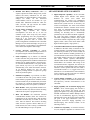
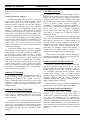
Console Application On-Line Programs
The C3 Maestro console application software consists
of three (3) main executable programs. All three are utilized
when the console is on-line with the CEC/IMC Digital
Audio Switch (the console-to-CIM serial control data link is
active); therefore, they are considered the “on-line”
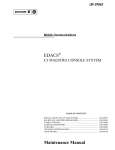
programs. The following block diagram illustrates program
interaction. For specific program file names and detailed
information, refer to the Administrator’s Manual,
AE/LZB 119 1897.
PERSONAL COMPUTER
POINTING DATA
FROM
MOUSE/TRACKBALL
MOUSE
PORT
O
S
GRAPHICAL
USER
INTERFACE
(GUI)
O
S
VIDEO
PORT
VIDEO
SIGNALS TO
MONITOR
OS
INPUTS FROM MIC
PTT BUTTONS,
FOOTSWITCHES,
DISPATCH
KEYBOARD, ETC.
DISPATCH
MANAGER
OS
SERIAL
PORT
O
S
COMMUNICATIONS
INTERFACE
INTERNAL
AUDIO
CONTROL
CIRCUITS
NOTE:
AUDIO INPUTS
AND OUTPUTS
NOT INDICATED.
OS
DATABASE DATA
TO/FROM
HARD DISK
DRIVE
O
S
O
S
ENHANCED
AUDIO
ENCLOSURE
AE/LZB 119 1892 R1A
O
S
START-UP
INITIALIZATION
DATA FROM HARD
DISK DRIVE
O
S
NOTES:
1. “OS” = OPERATING SYSTEM.
2. HARDWARE CIRCUITS NOT
INDICATED.
SERIAL
PORT
OUTPUT DEVICES
(RELAYS, ETC.)
SERIAL CONTROL DATA
TO/FROM CIM
Figure 1 – C3 Maestro On-Line Program Interaction
In some specialized cases, the GUI on-line program
may be replaced by or connected to a third-party
software application such as a Computer-Aided
Dispatch (CAD) peer-to-peer application. Cases of
this type are beyond the scope of this manual.
Dispatch Manager
The Dispatch Manager is the console’s main executable
on-line program. It links the other two on-line programs—
the GUI and the Communications Interface—together, it
maintains console databases and it performs many other
important functions for the console application.
The Dispatch Manager directly communicates with the
GUI and the Communications Interface by sending and
receiving data messages via operating system “pipes.” In
most all cases, the Dispatch Manager processes messages, as
needed, before passing data to the GUI or to the
Communications Interface.
Typically, data messages sent to the GUI are messages
which the Dispatch Manager has received from the
Communications Interface which originated from either the
console’s CIM within the CEC/IMC or from the console’s
audio system. Examples include, respectively, a radiooriginated call message from the CIM, and a console desk
microphone PTT button pressed message from the Enhanced
Audio Enclosure. Other messages sent to the GUI from the
Dispatch Manager include unit/group/conventional/console
entity database information and system error messages.
Data messages which the Dispatch Manager receives
from the GUI are primarily user input-type messages which
the Dispatch Manager must process and act upon
accordingly. The GUI receives mouse/track-ball (and/or
touch-screen) actions from the Windows NT operating
system, processes them as needed and then, if required
passes a corresponding user input-type message to the
Dispatch Manager. Examples include a module/entity select
action, a selected module/entity PTT action, module/entity
volume change actions, and many actions which involve PC
hard disk drive database file reads. Not all mouse/track-ball
actions which the GUI receives from the operating system
are passed on to the Dispatch Manager. Examples include
module picks, module page changes and command panel
changes.
Data messages which the Dispatch Manager sends to
the Communications Interface are primarily user input-type
messages which it has received from the GUI, processed,
and must be passed on to the CIM and/or the Enhanced
Audio Enclosure for processing. Examples include
mouse/track-ball generated console-originated call request
(PTT key/unkey) messages which must pass to the CIM and
13
AE/LZB 119 1892 R1A
DESCRIPTION
Enhanced Audio Enclosure, and mouse/track-ball generated
headset sidetone volume change messages which must pass
only to the Enhanced Audio Enclosure.
The Dispatch Manager also receives many different
type data messages from the Communications Interface.
Examples of messages which pass from the CIM through
Communications Interface to the Dispatch Manager include
radio-originated call messages, entity database transfer
messages, entity privilege list database transfer messages,
auxiliary input/output data messages and CEC/IMC network
status messages. Examples of messages which pass from the
Enhanced Audio Enclosure through the Communications
Interface to the Dispatch Manager include PTT key/unkey
messages, headset connected/unconnected messages, audio
level messages, and dispatch keyboard keystroke messages.
Communications Interface
The Communications Interface program provides data
support to the Dispatch Manager program for both the PCto-CIM and the PC-to-Enhanced Audio Enclosure serial data
links. Basically, it is a control data message translator and
router with three (3) main input/output data paths. The
Dispatch Manager program automatically starts this program
when it starts.
For console diagnostic/troubleshooting periods, the
Communications Interface program also includes a simple
built-in real-time data message monitor. This monitor
displays receive and transmit serial data link messages in a
hexadecimal (base 16) format. To enhance user monitoring,
receive data messages are displayed in a different color from
transmit data messages on the same serial link. Displayed
data messages can also be logged to the PC’s hard disk drive
in the hexadecimal format for non-real-time monitoring.
Graphical User Interface (GUI)
The Graphical User Interface on-line program controls
all console screen information displayed on the monitor.
Since the monitor is the console’s only visual output
indication device, it is the key hardware component to the
GUI’s design. As previously described, the GUI also
receives user input mouse/track-ball (and/or touch-screen)
actions from the Windows NT operating system and
processes them as needed. Normally, when the Dispatch
Manager program starts it automatically starts this program;
however several different start-up options are possible.
Figure 2 thru Figure 5 are screen snap-shots from
typical dispatch sessions. Call-outs above and below each
screen identify major display items which are controlled by
the GUI.
At console start-up, the GUI reads a screen initialization
file stored on the PC’s hard disk drive to configure the
screen accordingly. This screen initialization file is highlyconfigurable thus allowing a great deal of customization to
14
the console’s GUI appearance. However, a separately
purchased software configuration program—the UserDefinable Screen (UDS) Configurator program—is required
to generate custom screen configurations/initialization files;
see page 17 for additional details. Figure 2 is a snap-shot of
the factory-supplied screen configuration (subject to change)
and Figure 3, Figure 4 and Figure 5 are snap-shots of
custom screen configurations which were generated with the
UDS Configurator program. Each figure shows only one
module page within the respective screen configuration.
After the GUI initializes the screen at start-up, it
switches to a normal operating mode in which it processes
incoming messages from the Dispatch Manager and
mouse/track-ball (and/or touch-screen) actions from the
operating system. As needed, it acts accordingly by updating
the screen via the operating system and/or by sending
corresponding data messages to the Dispatch Manager.
When needed, the GUI also periodically updates non-user
influenced areas on the screen such as the clock/time panel.
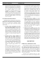
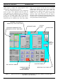
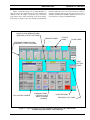
As previously stated, Figure 2 shows the factorysupplied screen configuration (subject to change). This
configuration consists of a total of eight (8) module pages as
indicated by the number of buttons on the page button panel.
Module page A contains fourteen (14) standard
communication modules; page A is the currently chosen
module page. All standard communication modules on this
page are programmed per the entity names/aliases displayed
in the modules’ title bars, and the Dispatch Menu command
panel is chosen. Other notable items in this screen snap-shot
include a current console transmission on entity
“POLICE 1” programmed in module A1 per the “XMT”
indication in the module, and a simultaneous incoming
radio-originated call from unit “JONES_SG” on entity
“POLICE 4” programmed in module A4. In this example
EDACS radio system, entities “POLICE 1” thru
“POLICE 7” are EDACS trunked talk groups, entities
“FIRE 1” and “FIRE 2” are conventional channels and
entities “RESCUE 1” thru “RESCUE 5” are also EDACS
trunked talk groups.
Primary GUI display items are described briefly in the
following text. If necessary, refer to the console’s
Operator’s Manual for additional details on these items or
on secondary display items which are not discussed such as
the pop-up (“general”) dialog boxes:
•
Module Pages—Each module page can contain
one or more standard communication modules,
RSM modules, RTT modules and/or auxiliary
input/output (I/O) modules. Modules are
considered dynamic display items because they
appear and disappear when the chosen module page
changes; they are set-up on a per module page
basis. Module page selection is performed by the
page button panel located on the console’s screen
DESCRIPTION
using mouse/track-ball/touch-screen actions, or by
the page up/down keys on the dispatch keyboard
using keystroke actions. Up to eight (8) module
pages, identified page A thru page H, can co-exist
in each screen configuration. The maximum
number of modules (all types) on a single module
page is basically limited by the available screen
display area. This area changes as monitor
resolution changes are made and as other display
items are added/deleted.
•
Standard Communication Modules—The standard communication module is the console’s
fundamental communication indication and
console-originated transmission control display
item. Each is console user/dispatcher programmable with a single entity (trunked talk group,
INDIVIDUAL CALL PANEL
MESSAGE PANEL
STANDARD COMMUNICATION
MODULES (14 TOTAL THIS PAGE)
COMMAND PANEL
(“DISPATCH MENU”
SHOWN CHOSEN)
CALL HISTORY PANEL
AE/LZB 119 1892 R1A
individual radio unit, conventional channel or
another console) for incoming call monitoring and
outgoing console-originated call transmission
functions. Like module page A shown in Figure 2,
many of the factory-supplied screen configuration
module pages have fourteen (14) standard
communication modules each, with the modules
positioned in two rows of seven. As shown in
Figure 6, this positioning reflects the pick and
instant transmit key layout on the dispatch
keyboard. Up to 112 standard communication
modules can exist across multiple module pages
(within a single screen configuration).
•
Radio Status Message (RSM) Modules (see
Figure 4)—The RSM feature licensed option
provides EDACS radio unit transmitted status
VU METER PANEL
CLOCK PANEL
STATUS
PANEL
PAGE
BUTTON
PANEL
Figure 2 — Typical Console Screen with 14 Standard Communication Modules on Module Page A
(Resolution = 640 x 480 Pixels)
15
AE/LZB 119 1892 R1A
DESCRIPTION
monitoring at the console. Indications are displayed
in one or more RSM modules. Each RSM module
is assigned a status code number which corresponds
to a unique radio unit-transmitted status code
utilized throughout the EDACS radio system. 128
status codes are available for RSM and RTT
operations. Using a scrolling-type user interface,
each RSM module can display up to sixty-four (64)
radio units’ names/aliases which have transmitted
an equal status code (assigned to the RSM module).
Each listed name/alias is time-stamped when the
status code message is received by the console.
•
•
•
16
Request-To-Talk (RTT) Modules (see Figure
3)—The RTT feature licensed option is similar to
the RSM option except the dispatcher may, as
desired, individually reply to a unit requesting
communications with dispatch via a radio status
code
transmission.
Dispatcher
reply
is
accomplished via an individual call to the
desired/chosen unit with the dispatcher being the
caller and the requesting-to-talk unit being the
callee. The individual call is initiated directly from
the respective RTT module holding the queued-up
requesting-to-talk unit(s). RTT queue status is
indicated by displaying radio units’ aliases/names
or logical ID (LID) numbers within the particular
RTT module. Using a scrolling-type user interface,
each RTT module can display up to sixty-four (64)
radio units which have transmitted an equal status
code. Unlike RSM modules, RTT modules do not
time-stamp each radio unit listing.
Auxiliary Input/Output (I/O) Modules (see
Figure 5)—Using auxiliary I/O modules at the
console, a console user/dispatcher can monitor and
control the state of CEC/IMC auxiliary I/O events.
Auxiliary I/O is a feature licensed option at the
C3 Maestro console for Windows NT. Each
module is assigned to a specific CEC/IMC
auxiliary I/O event. Each has a large button at the
top and a small text line at the bottom. The large
button provides a text label identification area for
the assigned event, output control via the
mouse/track-ball/touch-screen if the assigned event
is an output type, and/or acknowledged control via
the mouse/track-ball/touch-screen if the assigned
event is an acknowledge input type. The small text
line at the bottom indicates the current event state
(active or inactive) via user-friendly text labels. As
the system requires, both the button labels and the
text line labels are customizable on a per-module
basis.
Page Button Panel—The console’s page button
panel—a static display item—provides two (2)
basic functions for the console’s module pages.
First, it is the GUI screen display item which
provides module page selection via the
mouse/track-ball/touch-screen; each button on the
panel can be pressed to select the corresponding
module page. Secondly, for all pages which are not
currently selected, each button highlights to
indicate an incoming call exists or an emergency
has been declared on at least one entity
programmed into a standard communication
module on the respective page.
•
•
•
•
Message Panel—The message panel—a static
display item—consists of two text lines which
indicate various messages to the console
user/dispatcher. The bottom-most line primarily
displays system and operator error messages. The
top-most line displays system-wide related
messages such as emergency declarations,
CEC/IMC auxiliary input/output (I/O) event state
transitions, and RSM and RTT radio status-related
messages. In most cases system-wide indications
are also displayed in another area of the screen. For
example, indication of an emergency declaration on
a trunked talk group also occurs in the standard
communication module programmed with the
respective group entity upon which the emergency
was declared.
Status Panel—The console’s status panel—a static
display item—contains six (6) small dedicated text
areas for various system status indications. These
indications include the console’s number
(CEC/IMC console assignment number), the
lowest-level EDACS trunked site operational status
of all trunked sites connected to the CEC/IMC
(full-feature trunking, failsoft trunking, etc.), Call
Director status (off hook), audio system off or
headset connected status (a shared area), CEC/IMC
database download status, and speaker audio mute
all status (of all unselected standard communication
modules).
Volume Units (VU) Meter Panel—Basically, the
VU meter panel—a static display item—displays
relative audio levels of transmit and receive audio
to and from the selected entity/module. Indication
is in a bar graph format. When the console is
receiving a call from the selected entity, the panel
displays the relative level of the audio incoming
from the CEC/IMC. When the console is
transmitting to the selected entity (or to any
unselected entity via an “instant” transmit
function), the panel displays the relative level of
transmit audio level being sent to the CEC/IMC.
Clock Panel—The clock panel—a static display
item—displays the current time in an
DESCRIPTION
hours:minutes:seconds
digital-type
format.
Typically, this time is set and maintained at the
CEC/IMC Manager. Time update messages are
periodically sent from the CEC/IMC to all consoles
connected to it via the respective CIM serial
control data links. Therefore, all consoles’ clock
indications are synchronized to the CEC’s/IMC’s
time. Thus consistent time indications are displayed
at all consoles interconnected to the CEC/IMC.
Also, any CEC/IMC time-stamped logging
corresponds with console time displays.
•
Call History Panel—The call history panel—a
static display item—continuously displays the last
four (4) select calls and the last four (4) unselect
calls received by the console. Each call is indicated
on a caller-to-callee basis in a respective select or
unselect list within the panel. When an incoming
call is received, the oldest call in the respective list
scrolls off the list.
NOTE
NOTE
Extended and detailed call history information is
available from three (3) separate pop-up (“general”)
dialog boxes (not show in a figure). One displays select
call history for the last forty-eight (48) callers, one
displays unselect call history for the last forty-eight
callers, and one displays call history on a per standard
communication module basis for the last twenty-four
(24) callers. See the console’s Operator’s Manual for
additional information.
•
Command Panels—The command panels, each
identified with a specific “menu” name, are the
GUI’s primary display items for console
user/dispatcher control via mouse/track-ball and/or
touch-screen actions. Only one is displayed
(chosen) at a time. Each command panel has fifteen
(15) buttons which are organized in a very userfriendly and simplistic manner for quick dispatch
operating versatility. On each command panel,
most buttons activate specific console operating
functions such as module volume up/down control
or transmit to (PTT) the selected entity; these
buttons are located mostly to the right and bottom
portions of each command panel. Other buttons on
each command panel are utilized to switch to other
command panels; these buttons are located mostly
to the left and top portions of each command panel.
Many command panels such as the Main Menu
command panel and the Dispatch Menu command
panel have common buttons to reduce panel-topanel switching requirements during typical
AE/LZB 119 1892 R1A
dispatch operations. Other command panels such as
the Emergency Menu command panel, the Patch
Menu command panel and the Simulselect Menu
command panel group buttons which control
specific functions which console can perform; these
panels also share some common/widely used
buttons such as the volume control buttons.
User-Definable Screen (UDS) Configurator
Off-Line Program (Optional)
As previously stated, the UDS Configurator program is
a separately purchased software program which allows generation of custom screen configurations for the console application’s graphical user interface. Generation is performed
by editing the factory-supplied screen initialization file and
then saving the edited file as required. The UDS Configurator edit session utilizes a graphical user interface which approximately mirrors how display item changes will appear in
the console application. Typically, one UDS Configurator
program is purchased per CEC/IMC and the program is
shared among all consoles connected to the CEC/IMC.
Almost all screen display-related parameters can be
changed via the UDS Configurator. Examples include the
positioning of each and every display item on the screen, the
number and type of modules on each module page, the total
number of module pages (8 maximum), color settings for
nearly all display items’ elements (including most text
colors), the screen’s background color, text labels on certain
buttons such as the buttons on the page button panel and the
buttons on auxiliary I/O modules, “setup” (console user profile) aliases/names, and full screen console GUI operation
enabled/disabled. Refer to the Installation and Set-Up
Manual included within this manual set for a complete overview of the screen-related changes possible with this program.
For complete details on the use of the UDS Configurator program, refer to its User’s Manual (AE/LZB 119 1896).
This manual is included with the UDS Configurator software
package.
Up to ten (10) different screen initialization files are
maintainable via the UDS Configurator at a given console/computer. Only one is active (utilized) when the console application is on-line. The active screen initialization
file is selected within a UDS Configurator edit session. If
done carefully, a screen initialization file may be shared
among (copied from/to) other consoles in the CEC/IMC
network system; see the UDS Configurator User’s Manual
for complete details.
Sample Screen Configurations
Generated with the UDS Configurator
The screen configuration snap-shots shown in Figure 3
thru Figure 5 were generated with the UDS Configurator.
17
AE/LZB 119 1892 R1A
DESCRIPTION
Again, Figure 2 shows the factory-supplied screen
configuration (with module page A chosen).
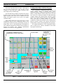
The UDS Configurator-generated screen configuration
shown in Figure 3 has significant differences from the
factory-supplied screen configuration. First, as indicated by
the number of buttons on the page button panel, it consists
of only two (2) module pages—page A and page B.
Reducing the screen configuration in this manner may be
beneficial purely for simplicity sake when many module
pages are not required. Second, only four (4) standard
communication modules exist on page A, the module page
chosen when the snap-shot was taken (notice the
highlighting on the Page A button). Third, two (2) RTT
modules exist on the page to provide request-to-talk
operations. Other notable differences from the Figure 2
snap-shot include the following repositioned display items:
call history panel, command panel (Main Menu chosen), VU
meter panel and the individual call panel.
REQUEST-TO-TALK (RTT)
MODULES (2 TOTAL THIS PAGE)
MESSAGE PANEL
STATUS
PANEL
STANDARD COMMUNICATION
MODULES (4 TOTAL THIS PAGE)
CLOCK PANEL
PAGE
BUTTON
PANEL
VU METER PANEL
CALL HISTORY PANEL
COMMAND PANEL
(“MAIN MENU”
SHOWN CHOSEN)
INDIVIDUAL CALL PANEL
Figure 3 — Typical Console Screen with 4 Standard Communication and 2 RTT Modules on Module Page A
(Resolution = 640 x 480 Pixels)
18
DESCRIPTION
Figure 4 snap-shot shows two (2) RSM modules on
page B. This screen configuration is the same configuration
utilized to take the Figure 3 snap-shot—only the chosen
page differs; notice equal positioning of the static display
items. Page A (Figure 3) has four standard communication
AE/LZB 119 1892 R1A
modules organized in two rows of two and two (2) side-byside RTT modules; whereas page B (Figure 4) has seven (7)
standard communication modules organized in one row of
seven and two (2) side-by-side RSM modules.
RADIO STATUS MESSAGE (RSM)
MODULES (2 TOTAL THIS PAGE)
MESSAGE PANEL
STATUS
PANEL
CLOCK PANEL
STANDARD COMMUNICATION
MODULES (7 TOTAL THIS PAGE)
PAGE
BUTTON
PANEL
CALL HISTORY PANEL
COMMAND PANEL
(“SPECIAL CALL
MENU” SHOWN
CHOSEN)
VU METER PANEL
INDIVIDUAL CALL PANEL
Figure 4 — Typical Console Screen with 7 Standard Communication and 2 RSM Modules
on Module Page B (Resolution = 640 x 480 Pixels)
19
AE/LZB 119 1892 R1A
DESCRIPTION
The screen snap-shots shown in Figure 2 thru Figure 4
have one notable common aspect—they all utilize a screen
resolution of 640 x 480 pixels. Higher resolutions allow
more display items per module page.
The snap-shot shown in Figure 5 illustrates this concept.
It utilizes a screen resolution of 800 x 600 pixels. With this
higher resolution, more screen area is available since each
display item appears smaller on the screen at the higher
resolution setting.
Other notable differences between the Figure 5 screen
configuration and the screen configurations shown in the
earlier figures include the relative repositioning of nearly all
display items, seven (7) total module pages, the addition of
more standard communication modules, and the addition of
auxiliary I/O modules. Also, standard communication
modules A11 thru A21 are not programmed.
Configuration Editor Off-Line Program
The C3 Maestro’s Configuration Editor program is an
off-line program utilized to configure many console
application settings. Configuration functionality includes the
ability to change hardware-related settings such as the baud
rate of the PC’s COM port utilized for CIM interfacing,
configure manual and preprogrammed (automatic) paging
buttons for integrated paging operations, define RSM/RTT
status codes prior to module addition via the UDS
Configurator, change start-up options of the Communication
Interface program’s monitor, and configure miscellaneous
settings such as various console application start-up options.
For detailed information on the Configuration Editor,
refer to Administrator’s Manual AE/LZB 119 1897 and/or
the program’s built-in help.
CLOCK PANEL
STANDARD COMMUNICATION
MODULES (23 TOTAL THIS PAGE)
AUXILIARY I/O
MODULES
(8 TOTAL THIS
PAGE)
PAGE
BUTTON
PANEL
INDIVIDUAL
CALL
PANEL
RSM
MODULE
(1 TOTAL
THIS PAGE)
CALL
HISTORY
PANEL
COMMAND
PANEL
MESSAGE
PANEL
VU
METER
PANEL
Figure 5 — Typical Console Screen at a Screen Resolution of 800 x 600 Pixels
20
STATUS
PANEL
DESCRIPTION
AE/LZB 119 1892 R1A
DISPATCH KEYBOARD
•
five (5) telephone/intercom keys
The C3 Maestro’s specially designed dispatch
keyboard, shown in Figure 6, adds tactile-feel keyboard
operation to the console thus providing dispatch speed
capability equal to a modular-type console. It provides easy
control for the advanced features of the C3 Maestro console.
Keys with similar functions are grouped together and the
most frequently used key groups are located near the bottom
of the keyboard for quick and easy access. For example,
transmit and module pick keys are located at the bottom.
Seldom used keys are located near the top of the keyboard.
Key groups include:
•
ten (10) function keys and an escape key
•
a selected module transmit (PTT) key
•
fourteen (14) module pick keys
•
fourteen (14) module instant transmit keys
•
nine (9) module control keys
•
three (3) emergency keys
•
nine (9) edit control keys
•
three (3) tone transmission keys
•
a numeric keypad (telephone style)
•
eight (8) common control function keys
•
five (5) simulselect keys
•
eleven (11) patch keys
Dispatch keyboard operation works in parallel with the
GUI user input pointing devices (mouse/track-ball/touchscreen). All common dispatcher actions can be performed
both at the dispatch keyboard and with a pointing device. In
most cases the console user/dispatcher can switch between
the different input devices when performing sequential
actions in a multi-action operation. For example, a standard
communication module programming operation can be
started with the dispatch keyboard and completed with the
mouse.
Some console installations may not utilize the dispatch
keyboard. With the exception of PTT devices connected to
the console’s audio system such as a desk microphone and a
footswitch, these installations rely strictly on the console’s
pointing device(s) for user inputs to the console. In these
cases, user input redundancy is lost because the dispatch
keyboard is usually stored out of the console
user’s/dispatcher’s reach or it is not connected to the console
at all. This loss of input redundancy may not be an issue in
many installations such as those which employ both a
mouse/track-ball and a touch-screen monitor.
The dispatch keyboard interfaces to the Enhanced
Audio Enclosure via a serial data link. When power is
applied to it from the Enhanced Audio Enclosure, a small
built-in speaker simulates key clicks upon key activations.
The keyboard is not classified as a field-serviceable unit.
C3 Maestro
ESC
F1
F2
F3
F4
F5
F6
F7
COMMON CONTROL FUNCTIONS
HELP
MAIN
MENU
MUTE
ALL
F8
F9
F10
SIMULSELECT
ICALL
SEL
S1
TELEPHONE/ICOM
PATCH
S2
P1
P2
P3
P4
SIMUL
VIEW
ALT
PRMPT
TX
DRCTR
TX
ICALL
TX
S3
MODULE SELECT
VOL
MODL
MUTE
MODL
MODFY
CONV
FUNCS
MODL
FUNCS
PICK
MODL
1
P1
TX
P2
TX
EMERGENCY
VOL
MODL
HIST
ALARM
RESET
PVT
EMER
CLR
P3
TX
P4
TX
P5
TX
MODL
3
MODL
4
MODL
5
MODL
6
MODL
7
MODL
1
TX
MODL
2
TX
MODL
3
TX
MODL
4
TX
MODL
9
MODL
10
MODL
11
MODL
12
MODL
13
MODL
14
MODL
8
TX
MODL
9
TX
MODL
10
TX
MODL
11
TX
CALL
ANSR
MODL
5
TX
MODL
12
TX
CALL
FUNCS
TONES
EMER
DECLR
ALERT
PULSE
MODL
6
TX
MODL
7
TX
WRBL
EDIT CONTROL
PAGE
UP
HOME
MODL
8
PHONE/ICOM
TX
INSTANT TX
MODL
2
CALL
HOLD
PATCH
VIEW
S4
MODULE CONTROL
CALL
RLSE
P5
MODL
13
TX
MODL
14
TX
HIST
SCRL
END
SELECTED TX
PAGE
DOWN
ABC
DEF
1
2
3
GHI
JKL
MNO
4
5
6
PRS
TUV
WXY
7
8
9
✴
O
#
CLR
ENTER
Figure 6 — Dispatch Keyboard
21
AE/LZB 119 1892 R1A
DESCRIPTION
ENHANCED AUDIO ENCLOSURE
The C3 Maestro console’s Enhanced Audio Enclosure
contains all audio interface, audio routing and dispatch
keyboard interface circuitry for the console system.
Basically, the unit consists of:
•
•
•
•
•
•
a metal case assembly
an ac-to-dc switching power supply located inside
the case assembly
an I/O Backplane Board located inside the case
assembly
an Audio System Board located inside the case
assembly
operating firmware which is part of the Audio
System Board
19-inch EIA rack-mount hardware (optional)
Typically, as shown in the photo on the front cover of
this manual, the Enhanced Audio Enclosure is placed on the
console furniture’s desk-top and the video display monitor is
set on top of it. However, it may be rack mounted in a
standard 19-inch cabinet or case; an optional rack-mount kit
is available. When rack mounted, the Enhanced Audio
Enclosure occupies two (2) vertical rack units
(3.5 inches/8.89 cm).
Case Assembly
The Enhanced Audio Enclosure's case assembly
provides housing for all major components within the unit.
As shown in the exploded-view assembly diagram in this
manual (page 27) the case assembly basically consists of a
lower steel frame assembly which includes the rear panel, a
upper steel frame (top cover), a molded plastic front panel
and miscellaneous assembly hardware. The case is
constructed with heavy-gauge sheet metal so heavy items
such as the console's video display monitor can be placed on
its top without causing case distortion.
Assemblies inside the case include the I/O Backplane
Board mounted on the rear panel, the power supply unit
mounted to the bottom of the case, and the Audio System
Board. With the top cover removed, the Audio System
Board slides into and out of the case between two (2) plastic
printed circuit board guides attached to the left and right
inner sides of the case. When fully-inserted, rectangular
96-pin DIN-type connectors on the Audio System Board
mate with 96-pin DIN connectors on the I/O Backplane
Board.
All cable interconnections to and from external
equipment are made via connectors at the Enhanced Audio
Enclosure's rear panel. Openings in the rear panel expose the
22
I/O Backplane Board's connectors so they may be mated
with connectors on the cables to and from external
equipment. For example, the desk mic's cable is equipped
with a male DB-9 connector which mates with a female
DB-9 connector labeled "DESK MIC" at the Enhanced
Audio Enclosure's rear panel. This female DB-9 connector is
J5 on the I/O Backplane Board.
Power Supply
As shown in the exploded-view assembly diagram
(page 27), the power supply is mounted to the bottom of the
Enhanced Audio Enclosure's case. This switching-type
power supply converts ac line power (nominal 115 Vac or
230 Vac, 50/60 Hz) to well-regulated 12 Vdc power for use
by the Audio System Board and the Speaker Assemblies
attached to the Enhanced Audio Enclosure. Other than fuse
replacement, the supply is not classified as a field-serviceable unit.
The ac on/off power switch is located on the Enhanced
Audio Enclosure's rear panel just above the detachable
IEC-320 type ac power cord connector. As viewed from the
back of the case, this switch and connector are located on
the left-hand side of the Enhanced Audio Enclosure's rear
panel.
A two-wire power cable between the power supply and
the I/O Backplane Board delivers twelve-volt dc (12 Vdc)
power to the I/O Backplane Board. The I/O Backplane
Board distributes this power to the Audio System Board via
the 96-pin DIN connectors and to its four (4) DB-9 speaker
connectors at the Enhanced Audio Enclosure's rear panel.
Consequently, the power supply unit within the Enhanced
Audio Enclosure supplies dc operating power to all Speaker
Assemblies connected to the Enhanced Audio Enclosure. As
described later in this manual and in the speaker assemblies
manual included with this manual set, this dc power is utilized by the audio power amplification circuitry within each
connected Speaker Assembly.
I/O Backplane Board
Inside the Enhanced Audio Enclosure, the I/O
Backplane Board is vertically-mounted on the enclosure's
rear panel. This board is the junction point for all audio
interconnections into and out of the Enhanced Audio
Enclosure to and from external audio devices. Microphones,
headsets, speakers, CEC/IMC audio lines, etc., all terminate
at the I/O Backplane Board. In addition other
interconnections made at the I/O Backplane Board include
control-type connections such as the PC's serial control data
link, the dispatch keyboard serial link and, optionally,
interconnections to Call Director telephone equipment.
The I/O Backplane Board consists of twenty-one (21)
connectors, nineteen (19) of which extend through Enhanced
Audio Enclosure's rear panel for external device connec-
DESCRIPTION
tions. Of the three (3) internal connectors, two directly mate
with the Audio System Board. These two 96-pin rectangular
DIN-type connectors carry all audio and control signals
between the Audio System Board and the I/O Backplane
Board's externally exposed connectors. The remaining internal connector provides the dc input connection from the
power supply located under the Audio System Board. As
previously described, the I/O Backplane Board distributes
this dc power to the Audio System Board via DIN interconnections and to the four (4) DB-9 speaker connectors on the
rear panel. See LBI-39102 which is included with this manual set for I/O Backplane Board connector pin-out details.
Audio System Board
control and process all logical data signals to and
from the Audio System Board's I/O logic circuits.
These circuits include (non-inclusive listing) the
audio switching matrix, several serial ports, bi-state
logical inputs, and bi-state logical outputs. The
microcontroller circuits also read the on-board
analog-to-digital converter circuits used for
volume-unit (VU) meter indications and they control the tone generation circuits.
•
•
The Audio System Board is the heart of the Enhanced
Audio Enclosure. It accommodates all audio and logical
processing circuitry. Major circuits and functions:
•
•
•
•
Audio Input Circuits—These circuits provide
amplification, filtering and level-adjustment for all
audio signals applied to the Enhanced Audio
Enclosure's audio inputs. Input signals include mic
audio signals, balanced-line audio signals from the
CEC/IMC, balance-line audio signals from Call
Director equipment, and audio signals from
optional audio output devices such as an external
paging tone encoder (pager).
Audio Switching Matrix Circuits—The audio
switching matrix routes conditioned (amplified,
filtered, level-adjusted) input audio signals to the
appropriate audio output circuits using ten (10)
8 x 8 cross-point switch matrix integrated circuits.
All console audio signals are routed through the
matrix chips. Input audio signals are applied to the
"y" side of the matrix and output signals are sent
out from the "x" side. The audio matrix chips are
controlled (switched) via digital logic signals from
the on-board microcontroller circuits.
Audio Output Circuits—Prior to application to
the appropriate Enhanced Audio Enclosure output,
each audio signal on the output side of the audio
matrix (a switched-in signal) is applied to an audio
output circuit. Each audio output circuit provides
amplification/attenuation, impedance matching
and/or level-adjustment in the output path. Output
paths include headset earphone audio, low-power
speaker audio ("select" and "unselect" audio),
balanced-line audio signals to the CEC/IMC,
balance-line audio signals to Call Director
equipment (optional), and single-ended audio
signals to call-check recorders (optional).
Microcontroller Circuits—80C32-based microcontroller circuits on the Audio System Board
AE/LZB 119 1892 R1A
•
•
•
•
•
PC Serial Port Circuit—An RS-232 serial port
for control data communication with the PC.
Dispatch Keyboard Serial Port Circuit—This
serial port receives keystroke data from the
dispatch keyboard. Operating power for the
keyboard’s internal logic circuits is also delivered
to the keyboard via this serial port.
Expansion Serial Port Circuit—An RS-422 serial
port which permits interfacing to external seriallyinterfaced equipment. (Reserved for future use.)
Bi-State Logic Input Circuits—These circuits
interface bi-state logical sense lines from external
equipment connected to the Enhanced Audio
Enclosure to the Audio System Board's
microcontroller circuits. Examples
include
microphone PTT sense lines, microphone
connected/not connected sense lines, headset
connected/not connected sense lines, and Call
Director off hook and Call Director jack sense
lines. Each logic input line includes a pull-up
resistor and a low-pass filter circuit.
Bi-State Logic Output Circuits—These circuits
interface the microcontroller circuits to bi-state
logical output devices such as relay contacts. The
Audio System Board has a total of seven (7) onboard relays.
Analog-to-Digital Converter Circuit—The analog-to-digital (A/D) converter circuit's primary
function is to provide VU (Volume-Unit) data to
the PC on the selected module/entity transmit and
receive signal levels. The microcontroller reads the
A/D converter and it sends the read data to the PC
via the serial control data link. VU indications are
displayed in the console GUI’s VU meter panel in a
bar graph format. The A/D converter circuit is also
utilized during automated test and alignment
procedures.
Tone Generation Circuits—Tone generation
circuits on the Audio System Board include two (2)
sinewave generators which give the Enhanced
Audio Enclosure the ability to generate tones for
integrated paging operations. Therefore, an external
23
AE/LZB 119 1892 R1A
OPERATING PROCEDURES
paging tone encoder is not required if the
appropriate feature licensed software option is
available at the console. The tone generation
circuits are also utilized during automated test
procedures performed at the factory.
Firmware
The operating program code for the microcontroller
circuits within the Enhanced Audio Enclosure is stored on a
factory-programmed 128K x 8-bit read-only memory
(ROM) chip located on the Audio System Board.
Occasionally, code stored on this chip may change as circuit
improvements occur and/or as new features are added to the
Enhanced Audio Enclosure. The chip is socketed which
allows simple removal if replacement is necessary. Refer to
the console’s Software Release Notes (SRN-1000-xx) for
specific details.
The Speaker Amp Board is mounted just behind the
speaker on long metal stand-offs fastened to the assemblies
front panel. It amplifies low-power speaker audio signals
from the Enhanced Audio Enclosure and drives the speaker
with the amplified signal. It can drive the speaker with up to
five (5) watts of audio power. The interconnect cable
between the Enhanced Audio Enclosure and the Speaker
Assembly delivers both twelve-volt dc operating power and
the low-power speaker audio to the Speaker Amp Board.
OPERATING PROCEDURES
For complete operating procedures on the C3 Maestro
console for Windows NT, refer to Operator’s Manual
AE/LZT 123 1892.
INSTALLATION AND SET-UP
SPEAKERS KITS AND ASSEMBLIES
Speaker Kits used with the Enhanced Audio Enclosure
consist of mechanical hardware, one or more Speaker
Assemblies, and cables which interconnect each Speaker
Assembly to the Enhanced Audio Enclosure. For a given
enclosure, one Speaker Assembly is the "select speaker" and
the remaining are the "unselect speakers."
Speaker Kit mechanical hardware may be of several
different varieties providing either desktop speaker
operation in the form of a self-contained single-speaker case
or a rack-mount version in the form of a standard 19-inch
EIA rack mount assembly. Normally, rack-mount Speaker
Kits are factory equipped with two (2) Speaker
Assemblies—one select speaker and one unselect speaker. If
additional unselect speakers are required for a given
console, up to two additional Speaker Assemblies may be
added for a total of four (4) speakers in a 3-rack-unit-high
assembly.
NOTE
NOTE
See the table and parts lists in LBI-39104 for
Speaker Kits' contents.
Each Speaker Assembly consists of a high-quality
magnetically-shielded speaker, a Speaker Amp Board which
accommodates audio power amplification circuitry, a front
panel, a panel-mounted volume control potentiometer, and
mechanical hardware. This unit may be installed in the
desktop case or in the rack-mount frame. Since a
magnetically-shielded speaker is employed, this assembly
may be located near a video display monitor without causing
monitor distortion. The difference between the select and
unselect Speaker Assemblies is front panel labeling.
24
The Installation And Set-Up Manual included within
this manual set contains board-level configuration, cable
interconnection information and console application start-up
information. The manual also contains a detailed overview
of the advanced configurations possible for the console
including, including information on the feature licensed
options.
ADMINISTRATOR’S INFORMATION
System administration information for the C3 Maestro
console for Windows NT is available in a separatelysupplied
manual.
Administrator’s
Manual
AE/LZB 119 1897 includes detailed information on the
console application such as program file names and
functions, the optional console GUI-related configurations
which are possible, and the Configuration Editor off-line
program. It also includes in-depth information on the
console’s feature licensed options and configuration
information on Windows NT-related settings which
influence how the console application operates. Typically,
knowledge of the information presented in the
Administrator’s Manual is only required by administrative
personnel in the CEC/IMC network system who are
responsible for the system’s dispatch consoles.
MAINTENANCE
Enhanced Audio Enclosure and Speaker Assembly
disassembly instructions follow. Refer to the appropriate
maintenance manual included with this manual set for
detailed board-level maintenance information. These
maintenance manuals contain board outline and schematic
MAINTENANCE
diagrams, parts
descriptions.
lists
and
detailed
circuit
analysis
❑ Remove the top cover and front panel assembly
away from the bottom assembly by sliding the two
assemblies apart.
DISASSEMBLY INSTRUCTIONS
❑ Refer to LBI-39103 for Audio System Board
Enhanced Audio Enclosure
Disassemble an Enhanced Audio
accordance with the following instructions:
AE/LZB 119 1892 R1A
Enclosure
in
service information. Refer to LBI-39102 for I/O
Backplane Board service information. The power
supply is a non-serviceable unit; it should be
replaced in whole if a failure occurs (other than
fuse replacement).
❑ Power-down the Enhanced Audio Enclosure by
turning the on/off power switch on the back of
the unit to the OFF position.
❑ Disconnect the detachable ac power cord from
the back of the unit.
❑ Disconnection of other cables from the back of the
Enhanced Audio Enclosure is optional, as the top
cover may be removed with these cables connected.
❑ Lay the unit upside-down on a flat surface with the
front panel facing you.
❑ Using both index fingers, simultaneously depress
the two (2) recessed latching buttons on the sides of
the unit.
❑ With the latching buttons fully depressed, slide the
bottom of the unit approximately one (1) inch by
pushing the two (2) rubber feet nearest the front
panel away from the front panel.
❑ Carefully return the unit to an upright position. Use
caution as the top cover and front panel assembly
may easily separate (slide) from the bottom
assembly at this time.
Speaker Assembly
Disassemble a Speaker Assembly in accordance with
the following instructions:
❑ If necessary, disconnect the Speaker Assembly
from the Enhanced Audio Enclosure by unplugging
the cable at the rear of the Speaker Assembly. If
tightened, the cable's DB-9 connector securing
screws may need to be loosened using a small
screwdriver.
❑ If the Speaker Assembly is a desktop version,
disassemble it to gain access to the Speaker Amp
Board as follows: Remove the four (4) screws from
the back of the case and separate the case's front
and rear sections.
If the Speaker Assembly is a rack-mount version,
removal of the assembly from the rack-mount
frame is recommended: Remove the screws that
secure the Speaker Assembly to the rack-mount
frame.
❑ Refer to LBI-39104 for service information.
25
AE/LZB 119 1892 R1A
OUTLINE DIAGRAM AND PARTS LIST
8
5
6
2
(NOT
SHOWN)
3
7
12
4
1
9
13
(NOT
SHOWN)
10
11
(NOT SHOWN)
NOTE:
FURNITURE NOT SUPPLIED AS PART OF SYSTEM.
C3 MAESTRO CONSOLE SYSTEM
WITH ENHANCED AUDIO ENCLOSURE
(Made from 903-0001-000 Rev. 0)
C3 MAESTRO CONSOLE
FOR WINDOWS NT
ISSUE 1
DIAGRAM
ITEM
1
26
PART/OPTION
NUMBER
350A1371P13
DESCRIPTION
Personal Computer, C3 Maestro: Includes PC
CPU enclosure, RS-422 board, PC keyboard, 2button mouse, mouse pad, Windows NT
operating system software (installed and
configured to factory defaults), C3 Maestro
console application software (installed and
configured to factory defaults). Less monitor.
DIAGRAM
ITEM
PART/OPTION
NUMBER
DESCRIPTION
6
CRMC3E
Microphone, Boom (not shown in diagram).
7
CRMC5F
Microphone, Desk.
8
(See LBI-39104 for
part numbers)
Speaker, Desktop. (Rack-mount speakers are not
shown in diagram; see LBI-39104.)
9
CRCN1W
Jack Box, Headset.
10
CRSU3C
Footswitch, Dual.
11
CRSU3B
Footswitch, Single (not shown in diagram).
12
344A1371P29
Cable: 9-foot, male DB-9-to-female DB-9. (Used
for EAE-to-speaker audio interconnection and
PC-to-EAE serial data link interconnection.)
12
19B804083P2
Cable: 100-foot (Used for Console-to-CEC/IMC
audio interconnections).
Cable: 100-foot (Used for Console-to-CEC/IMC
RS-422 control data interconnections).
2
350A1371P14
Monitor, standard PC: 14-inch VGA.
2
350A1371P15
Monitor, standard PC: 17-inch SVGA.
2
350A1371P16
Monitor, touch-screen: 14-inch SVGA.
2
350A1371P33
Monitor, touch-screen: 17-inch SVGA.
12
19B804083P3
3
350A1371P4
(P29/7720040001)
Enhanced Audio Enclosure: Includes EAE and
one (1) 350A1371P29 cable for PC-to-EAE serial
link interconnection.
12
350A1371P43
Cord Kit: International AC.
13
P29/7590289000
(350A1371P30)
RS-422 Board (ESD protected).
4
350A1371P17
(P29/7590182003)
Keyboard, Dispatch: with DB-9 connector.
5
CRMC3F
Microphone, Gooseneck: 16-inch.
ASSEMBLY DIAGRAM
AE/LZB 119 1892 R1A
10
11
8
(x 1)
2
(x 5);
(not shown)
16
POWER SUPPLY
14
13 (x 2)
AUDIO SYSTEM BOARD
DANGER!
HIGH-VOLTAGE AREAS.
9
(x 4)
3
(x 4)
15
I/O BACKPLANE BOARD
12
32
30 (x 1)
37 (x 2)
REAR PANEL
PART OF ITEM 12
PART OF ITEM 15
POWER SUPPLY INTERCONNECTIONS
29
39 (x 2)
32
41 (x 4)
DANGER!
HIGH-VOLTAGE AREAS.
40 (x 7)
30
37 (x 2)
4
16
7
34
ENHANCED AUDIO ENCLOSURE
350A1371P4 (P29/7720040001)
(Made From 772-0040-XXX-HD, Rev. A)
27
AE/LZB 119 1892 R1A
ITEM
28
PARTS LISTS
ENHANCED AUDIO ENCLOSURE
350A1371P4 (P29/7720040001)
C3 MAESTRO CONSOLE
FOR WINDOWS NT
ISSUE 1
OPTIONAL HARDWARE & SOFTWARE
NOT INDICATED IN OUTLINE DIAGRAM ON PAGE 26
PART NUMBER
DESCRIPTION
1
P29/2A104C2404
Screw, machine: 4-40 x 1/4-inch, pan head
Phillips. (Qty. required = 4)
2
P29/2A106C2403
Screw, machine: 6-32 x 3/16-inch, pan
head Phillips. (Qty. required = 5)
3
P29/2A106C2404
Screw, machine: 6-32 x 1/4-inch, pan head
Phillips. (Qty. required = 9)
4
P29/2A104C2402
Screw, machine: 4-40 x 1/8-inch, pan head
Phillips. (Secures ground wire.)
5
P29/208A104020
Washer, lock: No. 4, spring, stainless
steel. (Qty. required = 4)
6
P29/208A106020
Washer, lock: No. 6, spring, stainless
steel. (Qty. required = 5)
7
P29/2080106000
Washer, lock: No. 4, internal tooth,
stainless steel. (Qty. required = 3)
ISSUE 1
PART/OPTION
NUMBER
350A1371P19
(P29/7720044000)
DESCRIPTION
Kit, Rack-Mount: 19-inch (for Enhanced Audio Enclosure).
350A1371P34
Track-ball.
350A1371P35
Card, PC Ethernet Combo.
350A1371P36
Memory: 256K Byte Cache (for HP P5/75 PC).
350A1371P38
Memory: 8M Byte System RAM (for HP P5/75 PC)
350A1371P39
Kit, External CD-ROM SCSI Disk Drive w/ SCSI-to-EPP
Interface Cable.
350A1371P48
UPS (Uninterruptible Power Supply), external: 110 Vac.
350A1371P49
UPS (Uninterruptible Power Supply), external: 220 Vac.
Software: Windows NT Resource Kit Version 3.51.
8
P29/2080028000
Washer, lock: No. 6, external tooth.
350A1371P40
9
P29/6110101000
Feet, rubber. (Qty. required = 4)
350A1371P41
Software: Windows NT Workstation Version 3.51 (CD-ROM).
10
P29/6050030000
Panel, front: molded.
350A1371P50
Software: Windows NT Service Pack.
350A1371P44
Software: RSM Feature Licensed Option. (Requires factory
licensing.)
350A1371P45
Software: Request-To-Talk
(Requires factory licensing.)
11
P29/6090546000
Enclosure, top.
12
P29/6090547000
Enclosure, bottom.
13
P29/6110100000
Guides, PCB: 6-inch (Qty. required = 2)
14
(See LBI-39103
for part number)
Board, Audio System.
350A1371P46
Software: Integrated Tone/Voice Paging Feature Licensed
Option. (Requires factory licensing.)
15
(See LBI-39102
for part number)
Board, I/O Backplane.
350A1371P47
Software: CEC/IMC Auxiliary I/O. (Requires factory licensing.)
16
P29/3860036000
Supply, Power: 12 Vdc @ 4.3 amp output.
350A1371P42
17
P29/6140231001
Label, Ericsson.
29
P29/3800133000
Connector: 2-position plug.
30
P29/3800188000
Receptacle: Fused IEC.
Kit, Retrofit: C3 Maestro for DOS to C3 Maestro for NT
upgrade package for HP P5/75 PC. Includes 256K byte cache
memory (350A1371P36), 8M byte RAM (350A1371P38),
Windows NT Workstation (350A1371P41), C3 Maestro
console application software for Windows NT, mouse and
mouse pad. (Requires CD-ROM drive for software installation:
350A1371P39 or equivalent.)
32
P29/3650049000
Switch, rocker: Lighted green.
34
P29/3710088000
Terminal, ring: No. 6 stud, 18-14 AWG.
35
P29/2010116000
Screw, machine: 4-40 x 1/4-inch, flat head
Phillips, stainless steel. (Qty. required = 2)
36
P29/2070073000
Nut, keeper: No. 4. (Qty. required = 2)
37
P29/3250077000
Fuse: 2.5 amp slow-blow, 5 x 20 mm. (Qty.
required = 2)
38
P29/3820021000
Cord, ac power: Right-angle IEC-320.
39
P29/3710007000
Terminal. (Qty. required = 2)
40
P29/3250003000
Terminal, quick disconnect: 0.187-inch.
(Qty. required = 7)
41
P29/1050034000
Tubing, heat shrink: 1/8-inch x 0.75-inch
(Qty. required = 4)
42
P29/5010150000
(350A1371P29)
Cable: DB-9 male/DB-9 male, 10-feet.
(Used for PC-to-EAE control data link.)
Feature
Licensed
Option.
INSTALLATION INSTRUCTIONS
ENHANCED AUDIO ENCLOSURE
(NOT INCLUDED WITH KIT. SHOWN
HERE FOR REFERENCE ONLY.)
AE/LZB 119 1892 R1A
INSTALLATION INSTRUCTIONS
1.
2.
3.
MOUNT TRAY (P29/6090561000) IN 19-INCH CABINET
OR CASE USING FOUR (4) #10-24 x 3/4 PHILLIPS PANHEAD SCREWS (P29/2040011000), FOUR (4) #10
LOCK-WASHERS (P29/2080005000), AND FOUR (4) #10
SPRING NUTS (P29/2070098000). THESE ITEMS ARE
NOT SHOWN IN DIAGRAM.
REMOVE FOUR (4) #6-32 PHILLIPS-HEAD SCREWS
SECURING RUBBER FEET TO BOTTOM OF
ENHANCED AUDIO ENCLOSURE. RETAIN THESE
SCREWS. DISCARD RUBBER FEET UNLESS
REVERSION BACK TO DESK-TOP USE MAY BE
NECESSARY IN FUTURE.
MOUNT ENHANCED AUDIO ENCLOSURE TO TRAY
USING FOUR (4) SCREWS REMOVED IN STEP 2.
RACK-MOUNT TRAY
#6-32 SCREW (4 PLACES)
(NOT INCLUDED WITH KIT. PARTS OF
ENHANCED AUDIO ENCLOSURE.)
ENHANCED AUDIO ENCLOSURE RACK-MOUNT KIT; OPTIONAL
350A1371P19 (P29/7720044000)
(772-0044-XXX-HD)
29
Ericsson Inc.
Private Radio Systems
Mountain View Road
Lynchburg, Virginia 24502
1-800-528-7711 (Outside U.S.A., 804-528-7711)
30
AE/LZB 119 1892 R1A
Printed in U.S.A.