1
LBI-39062
Mobile Communications
EDACS®
C3 MAESTRO CONSOLE SYSTEM
TABLE OF CONTENTS
INSTALLATION, SET-UP AND TESTING .......................................
BACKPLANE AND SPREADER BOARDS........................................
AUDIO PA BOARD............................................................................
AUDIO MATRIX BOARD..................................................................
I/O BOARD.........................................................................................
VOLUME CONTROLLER BOX.........................................................
LOGIC BOARD ..................................................................................
Maintenance Manual
LBI-39055
LBI-39063
LBI-39064
LBI-39065
LBI-39066
LBI-38719
LBI-38720
LBI-39062
TABLE OF CONTENTS
Page
SPECIFICATIONS...................................................................................................................................
3
INTRODUCTION.....................................................................................................................................
5
DESCRIPTION......................................................................................................................................... 5
PERSONAL COMPUTER ................................................................................................................ 5
Video Display Monitor ("CRT").................................................................................................... 5
Standard PC Keyboard .................................................................................................................. 6
CEC/IMC Interface ....................................................................................................................... 7
LOGIC BOARD................................................................................................................................. 7
DISPATCH KEYBOARD ("CUSTOM KEYBOARD").................................................................. 7
AUDIO TOWER................................................................................................................................ 8
Case Assembly .............................................................................................................................. 8
Power Supply ................................................................................................................................ 8
Backplane And Spreader Boards ................................................................................................... 8
Audio PA Board(s)........................................................................................................................ 8
All Console Installations ........................................................................................................ 9
Multiple Unselect Speakers or Call Director Patch Installation ............................................... 9
Audio Matrix Board ...................................................................................................................... 9
I/O Board ...................................................................................................................................... 10
VOLUME CONTROLLER BOX...................................................................................................... 10
CALL DIRECTOR PATCH.............................................................................................................. 10
OPERATING PROCEDURES................................................................................................................. 11
INSTALLATION, SET-UP AND TESTING ........................................................................................... 11
MAINTENANCE...................................................................................................................................... 11
OUTLINE DIAGRAM − C3 MAESTRO CONSOLE SYSTEM ............................................................ 12
PARTS LIST ...................................................................................................................................... 14
MECHANICAL PARTS − AUDIO TOWER .......................................................................................... 15
PARTS LIST ...................................................................................................................................... 15
This manual is published by Ericsson GE Mobile Communications Inc., without any warranty. Improvements and changes
to this manual necessitated by typographical errors, inaccuracies of current information, or improvements to programs
and/or equipment, may be made by Ericsson GE Mobile Communications Inc., at any time and without notice. Such
changes will be incorportated into new editions of this manual. No part of this manual may be reproduced or transmitted in
any form or by any means, electronic or mechanical, including photocopying and recording, for any purpose, without the
express written permission of Ericsson GE Mobile Communications Inc.
Copyright June 1994, Ericsson GE Mobile Communications, Inc.
2
LBI-39062
SPECIFICATIONS*
GENERAL
OPERATING VOLTAGE
92 − 130 and 185 − 260 Vac (automatic selection),
47 − 63 Hz
MAXIMUM POWER CONSUMPTION
Audio Tower
Personal Computer System
200 Watts
(see manufacture's specifications)
OPERATING TEMPERATURE RANGE
0° to 75° Fahrenheit
DIMENSIONS (height x width x depth)
Audio Tower
Volume Controller Box
Personal Computer System
18 x 6.5 x 15 inches
2.25 x 12 x 13 inches
(see manufacture's specifications)
WEIGHT
Audio Tower
Volume Controller Box
Personal Computer System
27 lbs.
8 lbs.
(see manufacture's specifications)
CEC/IMC CONTROL DATA CONNECTION
AUDIO INPUTS
MICROPHONES
Supervisor and Operator Headsets
Desk Mic
Boom or Gooseneck Mic
9.6k or 19.2k baud RS-232 or RS-422 full-duplex serial
connection between the console's Personal Computer (PC)
and the Console Interface Module (CIM) within the
CEC/IMC. Data modems may be employed between the PC
and CIM.
Inputs for two simulated carbon telephone-style headset
microphones similar to Plantronics model HS-0309-1.
Typical input = 280 mVp-p. ALC/clipping threshold = 600
mVp-p. DC bias = 3.0 ±0.5 Vdc at 50 ohms.
Input for an electret-type microphone similar to Ericsson GE
part number 19C851086P10 or P11. Typical input = 300
mVp-p. ALC/clipping threshold = 600 mVp-p. DC bias = 5.7
±0.5 Vdc at 1000 ohms.
Input for a dynamic microphone similar to Shure Bros. model
VR300 / Ericsson GE part number 19C337100P1. Typical
input = 4.4 mVp-p. ALC/clipping threshold = 9.5 mVp-p. No
dc mic bias provided.
LINE A, B, C & D
Balanced 2-wire 600-ohm inputs each designed to receive
voice bandwidth audio from one pair of a 4-wire 600-ohm
twisted-pair transmission system provided by the CEC/IMC.
Capacitively coupled and transformer isolated. Typical input
= -5 dBm. Input range = -20 to +10 dBm.
CALL DIRECTOR PATCH (LINE D)
Balanaced 600-ohm input designed to accept audio from a
Call Director device similar to Plant Equipment model 3780L1-TT-010. Capactively coupled and transformer isolated.
Typical input = -25 dBm. Input range = -37 to +8 dBm.
PAGER
Unbalanced 600-ohm input designed to accept audio from a
paging tone encoder or similar device. Typical input = 140
mVp-p. Input range = 28 mVp-p to 2.0 Vp-p.
3
LBI-39062
OTHER INPUTS
MICROPHONE PTT AND MONITOR SWITCH
MICROPHONE SENSE
Active-low inputs used to sense the connection of a
microphone. Typical open-circuit voltage = 12 Vdc. Max.
open-circuit voltage = 16 Vdc. Max. short-circuit current =
30 mA
PAGE PTT
Active-low input used to signal presence of paging signal on
paging audio input. Typical open-circuit voltage = 12 Vdc.
Max. open-circuit voltage = 16 Vdc. Max. short-circuit
current = 30 mA
AUDIO OUTPUTS
EARPHONES
Supervisor and Operator Headsets
SPEAKERS
Select and Unselect(s)
Outputs for two telephone-style headset earphones similar to
Plantronics model HS-0309-1. Typical output = 300 µW (-5
dBm) into 600 ohms. Max. output power before limiting =
3.5 mW (+5 dBm) into 600 ohms.
Audio power amplifier differential outputs designed to drive
3.2 to 16-ohm speakers. Max. output power selectable to 5 or
8 watts (minimum) into 8 ohms at full volume. Max. number
of unselect speakers = 3.
LINE A, B, C & D
Balanced 2-wire 600-ohm outputs each designed to transmit
voice bandwidth audio to one pair of a 4-wire 600-ohm
twisted-pair transmission system provided by the CEC/IMC.
Capacitively coupled and transformer isolated. Typical output
= -5 dBm. Output range = -20 to +10 dBm.
CALL DIRECTOR PATCH (LINE D)
Balanaced 600-ohm output designed to deliver audio to a Call
Director device similar to Plant Equipment model 3780-L1TT-010. Typical output = -5 dBm. Output range = -20 to 0
dBm.
SELECT & UNSELECT RECORDERS
Unbalanced 600-ohm outputs each designed to drive audio
inputs of an external recording device. Capacitively coupled.
Typical output = -5 dBm. Output range = -20 to +2 dBm.
RELAY CONTACT OUTPUTS
*
Active-low inputs used to detect "dry-contact" switch closures
of the type found in standard microphones, footswitches and
headset jacks. Typical open-circuit voltage = 12 Vdc. Max.
open-circuit voltage = 16 Vdc. Max. short-circuit current =
30 mA.
Form-A (SPST normally-open dry contacts) relay connections
isolated from ground and all other signals. One relay activates
on console PTTs. Two others are activated via reserved
keystrokes at the Dispatch Keyboard. Contact rating = 0.75
amps at 26 Vdc. Ground isolation = 500 Vrms (60 Hz). Open
contact isolation = 500 Vrms (60 Hz).
These specifications are intended primarily for the use of the serviceman. See the appropriate Specifications Sheet for complete specifications.
CREDITS
IBM is a registered trademark of International Business Machines Corporation.
PC-AT is a trademark of International Business Machines Corporation.
MS-DOS is a registered trademark of Microsoft Corporation.
4
LBI-39062
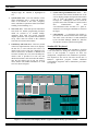
INTRODUCTION
®
The EDACS C3 Maestro console system is a state-ofthe-art CRT-based dispatch console system designed to
interface to an EDACS® CEC/IMC Digital Audio Switch.
It provides enhanced console dispatch features on a PCAT™ computer platform. A standard C3 Maestro console
system consists of:
•
•
•
•
®
an IBM PC-AT compatible Personal Computer
(PC) system running MS-DOS software and
custom C3 Maestro application software, a color
video display monitor ("CRT") and a standard PC
keyboard
a Dispatch Keyboard typically referred to as the
"Custom Keyboard"
a specialized Logic Board installed in one of the
PC's internal expansion slots
a specialized Audio Tower which provides audio
conditioning, routing and amplification functions
•
a Volume Controller Box for the speakers
•
a set of speakers (typically two)
•
other accessories such as headsets, microphones
and footswitches
The Audio Tower consists of:
• a case assembly
Using the C3 Maestro console, a dispatcher can
monitor and communicate with a large number of
personnel on the EDACS CEC/IMC network. A typical C3
Maestro console installation is shown in the Outline
Diagram drawing in this manual (page 12).
The PC's video display monitor displays graphical
representations of the radio links which are currently being
controlled by the dispatcher. Using the Dispatch Keyboard
("Custom Keyboard"), a dispatcher can issue commands to
control receive and transmit audio signal routing between
the CEC/IMC and audio devices connected to the C3
Maestro such as microphones and speakers. These keyboard
commands are sent to the PC. Software running on the PC
in-turn controls audio matrix switching circuitry inside the
Audio Tower via the Logic Board and the related
interconnect cable.
PERSONAL COMPUTER
The PC within the C3 Maestro console system provides
all computer processing functions for the console. Software
includes the Microsoft's MS-DOS operation system and a
custom C3 Maestro application program developed by
Ericsson GE. This custom program automatically starts
when the computer is "booted". PC components also
include the video display monitor ("CRT") and a standard
PC keyboard.
Video Display Monitor ("CRT")
•
a power supply
•
Backplane and Spreader Boards
•
DESCRIPTION
one Audio PA Board (2-speaker system) or two
Audio PA Boards (3- or 4-speaker system or if
interfaced to a Call Director for Call Director
patch operations)
•
an Audio Matrix Board
•
an I/O Board
The C3 Maestro console's video display monitor
("CRT") and keyboard replace the array of controls and
indicators found on traditional modular/desktop-type
consoles. Standard headsets, microphones, footswitches and
speakers can be connected to the C3 Maestro. Also, a
variety of other external inputs and outputs are supported.
NOTE
Refer to LBI-38662 for a complete description of
the EDACS CEC/IMC Digital Audio Switch.
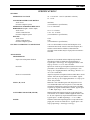
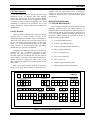
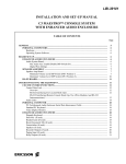
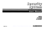
The PC's video display monitor provides all visual
dispatch control indications to the operating dispatcher.
This color monitor is typically of a VGA or super-VGA
resolution. Basic screen layout is shown in Figure 1. Screen
areas include:
•
Module Display Area − Fourteen (14)
communication modules are displayed at all times
in the upper portion of the screen. Each module
provides instant communication access to a talk
group, an individual unit, a conventional channel,
or another console. Eight (8) pages of fourteen
(14) modules are available for a total of 112
unique communication modules. Each module can
be programmed by the console operator.
•
Module Page Area − This area, located in the top
right-hand side of the screen, indicates which one
of the eight (8) module pages is displayed. When a
call is received on a non-displayed page, the
respective page indicator is high-lighted in yellow.
If an emergency call is received on a non-
5
LBI-39062
displayed page, the indicator is high-lighted in
red.
•
System Status Area − This area indicates various
status information such a console ID number,
name or ID number of the caller, emergency
status, and EDACS operational status (full-feature
trunking, failsoft trunking, etc.).
•
Note Card Area − Note cards provide instructions
and menus for module programming functions
which are referred to as "module modify"
operations. Note cards also provide advanced
dispatch operations such as patch and simulselect
set-up. These cards are located on the left-hand
side of the screen below the modules.
•
Call History and Scroll Area − This area, located
in the lower right-hand side of the screen, displays
the last five (5) select calls and the last five (5)
unselect calls received. The list is displayed on a
caller-to-callee basis. In addition, a detailed scroll
list of the last thirty-two (32) select and thirty-two
unselect calls is provided. For each call, this
detailed list includes caller and callee ID numbers,
time the call started, type of call, site used by
caller, and the call's module information. A scroll
list is not shown in Figure 1.
A2
A1
A1
POLICE-1
POLICE-1 POLICE-2
A3
POLICE-3
•
System Message/Command Line Area − This
area, located at the bottom left-hand side of the
screen, displays prompts and operator-entered data
such as radio ID numbers. Various system
messages are alsodisplayed in this area such the
up/down status of the CEC/IMC-to-console control
data
communication
link
and
successful/unsuccessful execution of a patch or
simulselect. No messages/commands are shown in
the figure.
•
Clock Display − A continuous time display is
provided (12 or 24-hour format) in the lower right
side of the screen. The time is set and maintained
by the CEC/IMC Manager (MOM PC); therefore
all consoles' clocks are synchronized together.
Standard PC Keyboard
During dispatch operations, the standard PC keyboard
is not used. However, during the console set-up process,
access to this keyboard is required for basic file
management, configurations and maintenance operations.
This keyboard is also used to exit and re-execute the C3
Maestro's application program if/when additional
configuration, diagnostic and/or maintenance procedures
are required.
A4
FIRE-1
A5
FIRE-2
A6
A7
A11
A12
A13
A14
PVT
A8
TRACEY P
A9
JONES BM
A10
FARRIS P
MODULE MODIFY
F1 = Program Unit
F2 = Program Group
F3 = Program Conventional
F4 = Program Phone
F5 = Program Console
F9 = Delete (Unprogram)
F10 = Save Module Setup
15511
ADAMS BM
BROOK TP
DELL JP
FARRIS P
AP
GULF
LM
HICKS QP
JONES BM
KELLY TM
MAN
TM
NANCE WM
SMITH JP
PAGE
PAGE-A
PAGE-B
PAGE-C
PAGE-D
PAGE-E
PAGE-F
PAGE-G
PAGE-H
STATUS
CON02
TRNK
SU_1
UNSELECT HIST
DELL JP to
BROOK TP to
DELL JP to
JONES BM to
JONES BM to
POLICE-2
POLICE-2
POLICE-2
POLICE-2
FIRE-1
SELECT HIST
KELLY TM to
SMITH JP to
FARRIS P to
SMITH JP to
JONES BM to
POLICE-1
POLICE-1
POLICE-1
POLICE-1
POLICE-1
Figure 1 − C3 Maestro Video Display Monitor (Typical; Module Modify Operation Shown)
6
LBI-39062
CEC/IMC Interface
The PC's COM1 serial port provides the control data
connection for the C3 Maestro. This serial data link
between the Maestro and the Console Interface Module
(CIM) within the CEC/IMC can be configured for RS-232
or RS-422 operation. Detailed configuration and wiring
information is contained in the Installation, Set-Up and
Testing maintenance manual (LBI-39055) included with
this manual set.
LOGIC BOARD
The Logic Board is installed in one of the PC's internal
expansion slots. It contains interface circuitry for the
Dispatch Keyboard and theAudio Tower. Connections are
made at the Logic Board's rear cover plate on the back of
the PC. The Dispatch Keyboard connects to the Logic
Board via a round 4-pin interlocking plug and the Audio
Tower connects via an interconnect cable with DB-37
subminiature type connectors on both ends.
Using the Logic Board, all Audio Tower functions are
controlled via the 37-conductor interconnect cable.
Basically, this cable provides a parallel-type interface.
Switching signals are sent through the cable only when an
event, such as a console PTT, occurs. Other than PTT pullup and Vu meter dc voltages, the cable is idle at most
times. This prevents induction of unwanted signals into the
audio system.
Many console audio routing functions are controlled
directly by the Logic Board without PC intervention. For
F1
ESC
F2
F3
F4
F5
F6
F7
F8
F9
example, when the Logic Board senses a microphone
change via a mic jack sense line from the Audio Tower, it
switches the matrix circuitry on the Audio Matrix Board
appropriately.
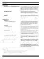
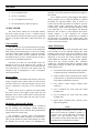
DISPATCH KEYBOARD
("CUSTOM KEYBOARD")
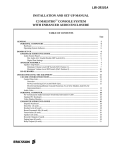
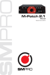
The C3 Maestro's Dispatch Keyboard provides instant
dispatcher operations. Keys with similar functions are
grouped together and most frequently used key groups are
located near the bottom of the keyboard for quick and easy
access. For example, transmit and module pick keys are at
the bottom. Seldom used keys are located near the top of
the keyboard. Key groups include:
•
a selected transmit (PTT) key
•
fourteen (14) module pick keys
•
fourteen (14) instant module transmit keys
•
nine (9) module control keys
•
three (3) emergency keys
•
nine (9) edit control keys
•
three (3) tone keys
•
a numeric keypad (telephone style)
•
eight (8) common control function keys
C3 Maestro
F10
COMMON CONTROL FUNCTIONS
SIMULSELECT
PATCH
MAIN MUTE ICALL
HELP MENU ALL SEL
S1
P1
PRMT DRCR ICALL
TX
TX
TX
S3
ALT
MODULE CONTROL
MODULE
SELECT
VOL VOL MODL MODL CONV MODL MODL PVT
MUTE MDFY FNCS FNCS HIST
PICK
MODL MODL MODLMODL MODL MODL MODL
1
2
3
4
5
6
7
MODL MODL MODLMODL MODL MODL MODL
8
9
10
11
12
13
14
S2
S4
SIMUL
VIEW
P1
TX
P2
P2
TX
TELEPHONE/ICOM
P3
P3
TX
P4
P4
TX
P5
P5
TX
PTCH
VIEW
EMERGENCY
TONES
ALRM EMR EMR
RST CLR DCLR
ALRT PLSE WRBL
INSTANT TX
MODL MODLMODL MODL MODL MODLMODL
1
2
3
4
5
6
7
TX
TX
TX
TX
TX
TX
TX
MODL MODLMODL MODL MODL MODLMODL
8
9
10
11
12
13
14
TX
TX
TX
TX
TX
TX
TX
CALL CALL CALL
RLSE HOLD ANSR
PHN / ICOM CALL
TX
FNCS
ABC
EDIT CONTROL
PAGE
UP
HOME
HIST
SCRL
END
PAGE
DWN
DEF
1
2
3
GHI
JKL
MNO
4
5
6
PRS
TUV
WXY
7
8
9
*
0
#
CLR
ENTER
SELECTED TX
Figure 2 − C3 Maestro Dispatch Keyboard
7
LBI-39062
•
five (5) simulselect keys
•
eleven (11) patch keys
•
five (5) telephone/intercom keys
•
ten (10) function keys and an escape key
AUDIO TOWER
The Audio Tower contains all of the audio interface
and audio routing circuitry for the C3 Maestro console
system. This unit is interfaced to the PC by the Logic Board
and the 37-conductor interconnect cable between the two
units.
furnishes 15 Vdc interconnections from the power supply to
these boards.
In a C3 Maestro console system equipped with multiple
unselect speakers, two (2) Audio PA Boards are required.
Essentially, the Spreader Board's earns its name in a
console system of this type because it expands or "spreads"
volume control wiper connections from the Volume
Controller Box toboth Audio PA Boards within the Audio
Tower. Basically, it is a "Y" cable adapter. The Spreader
Board also has an LED ac power indicator and currentlimited auxiliary 15 Vdc connections for external
equipment. The aux. 15 Vdc connections are available at
the removable screw-terminal type terminal block. This
terminal block is located on the rear vertical panel adjacent
to the ac on/off power switch.
Case Assembly
The Audio Tower's case provides housing for all major
components within the unit. As shown in the Mechanical
Parts drawing in this manual (page 15), the case assembly
consists of a frame support assembly, a card cage assembly,
side panels, front and rear door assemblies, and other
miscellaneous items. A lock is included on the rear door to
prevent access by unauthorized persons.
All cables are routed out of the bottom of the case
through the cut-out in the bottom of the rear door. If
necessary, some or all of the cables can be routed under the
case's stand and out to the front of the Audio Tower. For
example, it may be advantageous to route a microphone
cable in this manner.
Audio PA Board(s)
Primary circuits on the Audio PA Board in the Audio
Tower include two 4-wire 600-ohm balanced line audio
coupling circuits and two audio power amplifier circuits.
The balanced line audio coupling circuits provide audio
interfacing to and from the Console Interface Module
(CIM) within the CEC/IMC. The audio power amplifier
circuits drive the consoles speakers. The board also
contains two relayoutput circuits and two optically-coupled
digital inputs. From top to bottom, the connectors on the
board's panel provide:
•
Power Supply
•
As shown in the Mechanical Parts drawing, the power
supply is mounted in the bottom of the case near the front
end of the Audio Tower. This power supply converts ac line
power to regulated 15 Vdc power. It is a non-serviceable
unit.
•
Fifteen volts dc power is applied to all boards within
the Audio Tower by the supply's output cables and the
Backplane. The ac power on/off switch is located near the
bottom of the rear vertical panel just above the ac power
cord connector.
•
Backplane And Spreader Boards
The Backplane and Spreader Boards are installed in
the case assembly. The "Backplane" actually mounts on
rails near the Audio Tower's front-end. The Spreader Board
mounts on the rear vertical panel.
The Backplane provides signal interconnections
between the slide-in boards installed in the Audio Tower.
These boards include the Audio Matrix Board, the Audio
PA Board(s) and the I/O Board. The Backplane also
8
•
•
select and unselect speaker audio outputs (Speaker
A and B respectively; terminal block connector)
speaker volume control connections from Volume
Controller Box via Spreader Board and associated
cables (DB-9 subminiature connector)
relay Form-A contact outputs (terminal block
connector)
Line A balanced line audio input and output
(modular jack)
Line B balanced line audio input and output
(modular jack)
digital inputs (terminal block connector; these
inputs not supported)
NOTE
In the dispatch environment, "select" audio is
audio received from the dispatcher's primary or
"selected" entity (group, individual, conventional
channel, etc.) and "unselect" audio is audio
received from all other entities which are currently
programmed into communication modules.
LBI-39062
In a typical C3 Maestro console installation, the Audio
Tower is equipped with only one Audio PA Board (#1) and
this board is installed in the slot position adjacent to the
Audio Matrix Board. In this installation, a blank cover
plate is installed over the unused far right-hand slot
position. However, a 3- or 4-speaker console or console
connected to a Call Director requires a second Audio PA
Board (#2) installed in the Audio Tower's far right-hand
slot position. In this case, the blank cover plate is not
employed.
Line A output (destination). This audio is applied to
channel 1 of the console's CIM within the CEC/IMC.
Other Audio Matrix Board functions/circuits include:
•
•
•
All Console Installations
All C3 Maestro console installations use Line A on the
first Audio PA Board (#1) to couple select audio from the
CIM and mic audio to the CIM. Also, one-half of Line B
(the input pair) is used to couple unselect audio from the
CIM. The other half of Line B (the output pair) is not used.
Line A and B are connected to CIM channels 1 and 2
respectively.
Speaker A output drives the select speaker and Speaker
B drives the first unselect speaker. Some installations may
not employ speakers and thus connection to the speaker
outputs are not required.
Multiple Unselect Speakers or
Call Director Patch Installation
In a multiple unselect speaker or Call Director patch
installation, Line A and B balanced lines at the second
Audio PA Board (#2) are considered Line C and D
respectively. These balanced lines couple to CIM channels
3 and 4 respectively. One-half of Line C (board #2 Line A)
carries the second (2) unselect audio from CIM channel 3;
the other half (the output pair) is not used. Line D (board
#2 Line B) couples Call Director patch audio to and from
the CIM or, if no Call Director patch is present, it may be
used to couple the third (3) unselect audio to the console
from CIM channel 4. Unselect audio speaker routing
configuration is accomplished using the console's "MODULE
FUNCTIONS" note card.
Audio Matrix Board
The primary purpose of the Audio Matrix Board in the
Audio Tower is to route or switch audio signals from an
input source(s) to the appropriate output destination(s).
This routing is accomplished via audio matrix circuitry on
the board as controlled by the PC and the Logic Board. The
PC and Logic Board control the Audio Matrix Board (and
all other circuitry in the Audio Tower) via the 37-conductor
interconnect cable.
For example, when a dispatcher keys the desk mic, the
PC commands the Audio Matrix Board to switch the desk
mic audio input (source) through the audio matrix to the
•
•
•
•
audio conditioning for the supervisor headset,
operator headset, desk mic and boom/gooseneck
mic inputs
mic PTT interfacing to the PC
mic sense (connected/not connected) interfacing to
the PC
headset audio amplification for the supervisor and
operator headset earphone audio outputs
pager audio input coupling and
enable/disable input interfacing to the PC
page
Call Director patch coupling audio and control
interfacing
relay drive logic
Audio routing on the Audio Matrix Board is
accomplished via the audio matrix. This matrix consists of
eight (8) "cross-point switch" integrated circuits which
each have an 8 x 8 switch matrix. All console audio signals
are routed through the matrix ICs. Input signals are applied
to the "Y" side of the matrix and output signals are sent out
from the "X" side. Audio matrix and other circuitry on this
board is controlled by the Logic Board inside the PC and
the C3 Maestro application program running on the PC
From top to bottom, the connectors on the Audio
Matrix Board's front panel provide:
•
•
•
•
•
supervisor headset mic and earphone connections
(DB-9 subminiature connector)
operator headset mic and earphone connections
(DB-9 subminiature connector)
desk mic
connector)
connections
boom or gooseneck mic
subminiature connector)
(DB-9
subminiature
connections (DB-9
PC interfacing (DB-37 subminiature connector)
Several microphones may be concurrently connected to
the C3 Maestro console system via the Audio Matrix Board.
These include the mics in the supervisor and operator
headsets, a desk mic, and a boom or gooseneck mic. Mic
jack sense circuitry on the Audio Matrix Board and the
Logic Board within the PC determine which mic audio
signal will be used when the console is keyed. The console
may be keyed from either the Dispatch Keyboard, a push-
9
LBI-39062
to-talk (PTT) button at one of the connected mics or a
footswitch.
A pager audio input is provided at the I/O Board.
When enabled, paging audio overrides all other mic audio
inputs.
I/O Board
The I/O Board used in the Audio Tower interconnects
signals between the Audio Tower’s Backplane Board and
the terminal blocks and connectors located on its front
panel. In a typical C3 Maestro console installation, no or
only a few devices are interconnected the I/O Board. It
contains no active electronic components.
The I/O Board is inserted into the Audio Tower's far
left-hand slot. From top to bottom, connectors on the
board's panel provide:
•
•
•
•
•
•
•
•
select and unselect recorder
(terminal block connector)
audio
outputs
pager audio and pager enable ("PTT") inputs
(terminal block connector)
Call Director patch audio/control inputs and
outputs (DB-9 subminiature connector)
boom/gooseneck and monitor
(terminal block connector)
switch
inputs
footswitch 1 inputs for desk mic PTT and monitor
switch functions (DB-9 subminiature connector)
footswitch 2 inputs for boom/gooseneck mic PTT
and monitor switch functions (DB-9 subminiature
connector)
digital inputs (terminal block connector; these
inputs not supported)
relay Form-A contact outputs (terminal block
connector)
CALL
DIRECTOR
VOLUME CONTROLLER BOX
The Volume Controller Box contains volume controls
for the speakers. Normally, there are two (2) volume
controls, one for the select speaker and one for the unselect
speaker. This box is not required if the console is not
equipped with speakers.
Audio signals are not routed through the Volume
Controller Box. Instead, each volume control's
potentiometer sets a dc voltage which in turn controls the
gain of the respective speaker's audio amplifications
circuitry on the Audio PA Board.
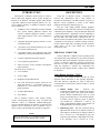
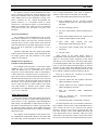
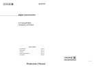
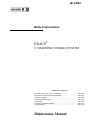
CALL DIRECTOR PATCH
The C3 Maestro console system can be connected to
Call Director (CD) telephone patch equipment. This feature
allows the C3 Maestro to "patch" a telephone line to a
specific unit, talk group, conventional channel or radio
patch in the CEC/IMC network. See Figure 3.
The term patch or patched, derived from phone patch,
is used to convey the CD is connected to the CEC/IMC. A
Call Director patch should not be confused with a radio
patch in which a collection of radio talk groups are
interconnected for common communications as one group.
Call Director patch operates independently of normal
console-to-radio dispatch communications. Using the CD
interface, the dispatcher is only required to connect the CD
with the target entity (unit, group, etc.). After this
operation, no other dispatcher intervention is required until
the CD patch must be disconnected.
Audio connections between the CD and the CEC/IMC
are done inside the C3 Maestro's Audio Tower as controlled
by the Logic Board within the PC. The console's
application program running on the PC has minimal
involvement in the control of CD patch audio switching.
As with other telephone interconnect calls, CD patch
calls operate in the message trunked mode. From the
standpoint of the radio user, a CD patch operates
identically to any other telephone interconnect call.
C3
MAESTRO
AUDIO
TOWER
CEC/IMC
Figure 3 − Basic Call Director Patch Audio Routing
10
AAAA
AA
AAAA
AA
AAAA
AA
AAAA
AA
AAAAAA
LBI-39062
The console uses a secondary LID (Logical ID) for the
patch channel requests, thus allowing CD patch operation
to work separately from, and concurrently with, the normal
console-to-radio dispatch communications. This LID is
referred to as the "Call Director ID".
If the C3 Maestro console is connected to a Call
Director, the Audio Tower must be equipped with two (2)
Audio PA Boards. The second board interfaces the CD
patch audio to CEC/IMC CIM channel four.
OPERATING PROCEDURES
Refer to the C3 Maestro Training Manual LBI-38660
for complete operation details. This manual includes User
Training Study Guide ECR-4488 and Administrators
Training Manual ECR-4489.
INSTALLATION, SET-UP AND
TESTING
Refer to maintenance manual LBI-39055 for
installation, set-up (configuration) and console system test
procedures. LBI-39055 is included with this manual set.
MAINTENANCE
Refer to the appropriate board maintenance manual
included with this manual set for board-level maintenance
information. These manuals include board outline and
schematic diagrams, parts lists, detailed circuit analysis
descriptions and board-level test and
alignment
procedures.
Ericsson GE Mobile Communications Inc.
Mountain View Road • Lynchburg, Virginia 24502
Printed in U.S.A.
11
LBI-39062
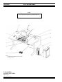
OUTLINE DIAGRAM
NOTE
See the parts list on page 14 for item descriptions.
3
4
NOTES:
1. FURNITURE NOT SUPPLIED AS PART OF SYSTEM.
2. ITEM 6 NOT SHOWN.
C3 MAESTRO
CONSOLE SYSTEM
Sheet 1 of 2
(Made from 903-0001-000 Rev. 0)
12
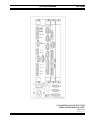
OUTLINE DIAGRAM
LBI-39062
C3 MAESTRO CONSOLE SYSTEM
AUDIO TOWER (REAR PANEL)
Sheet 2 of 2
(903-0007-000, Rev. 1)
13
LBI-39062
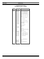
PARTS LIST
C3 MAESTRO CONSOLE SYSTEM
P29/7720033000 (344A3927P11) − 2 SPEAKERS
P29/7720033001 (344A3927P28) − 4 SPEAKERS
ISSUE 2
SYMBOL
PART NUMBER
DESCRIPTION
1
P29/7720032000
(344A3927P15)
Audio Tower (equipped for 2-speaker
operation − one Audio PA Boards).
1
P29/7720032001
(344A3927P46)
Audio Tower (equipped for 4-speaker
operation − two Audio PA Boards).
2
P29/7720035000
(344A3927P22)
Personal Computer, Keyboard and Logic
Board.
2
P29/7590282000
(344A3927P23)
Personal Computer, DOS and 14" Color
Monitor.
2
P29/7590245000
(344A3927P36)
Personal Computer and Keyboard.
3
P29/7590287000
(344A3927P37)
14" VGA Color Monitor.
4
P29/5050008002
(344A3927P12)
Volume Controller Box: 2-speaker.
4
P29/5050012002
(344A3927P41)
Volume Controller Box: 4-speaker (not
shown in diagram).
5
P29/7590182002
(344A3927P25)
Dispatch Keyboard.
7
CRMC3F
Gooseneck Microphone.
8
CRMC3D
Desk Microphone.
9
P29/3360011000
(344A3927P40)
Speaker.
10
CRCN1W
Headset Jacks.
11
CRSU3B
Footswitch, Single (not shown in diagram).
11
CRSU3C
Footswitch, Dual.
12
P29/5050006000
(344A3927P26)
Interface Cables. Includes:
P29/1030048000
Male DB-9-to-Male DB-9, 2 ft.
P29/1030049000
Male DB-15-to-Male DB-15, 10 ft.
P29/1030050000
Male DB-37-to-Male DB-37, 10 ft.
P29/3820021000
AC Power Cord, 5 ft.
-------------- ASSOCIATED PARTS --------------
14
P29/5000060001
(344A3927P24)
Logic Board.
P29/7590257002
(344A3927P38)
RS-422 Board (ESD protected).
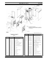
MECHANICAL PARTS
LBI-39062
FRONT
107
106
108
(4 PLACES)
107
102
103, 104
100, 101
106
105
NOTES:
1.
2.
EXPLODED VIEW FROM REAR.
SECOND AUDIO PA BOARD REQUIRED ONLY IF UNSELECT
SPEAKER 2 OR 3 USED OR IF CONSOLE IS INTERFACED TO
A CALL DIRECTOR.
SEE NOTE 2.
REAR
(MADE FROM 903-0002-000, Sh. 1, Rev. 1)
C3 MAESTRO AUDIO TOWER
MECHANICAL PARTS
ISSUE 2
SYMBOL
PART NUMBER
DESCRIPTION
SYMBOL
PART NUMBER
DESCRIPTION
103
P29/3800188000
Receptacle, IEC: ac power, fused.
104
P29/3250077000
Fuse, 2.5A slow blow. (Qty. of 2 required.)
105
P29/6090207101
Support, side. (Qty. of 4 required.)
1
P29/6090307001
Feet, base. (Qty. of 2 required.)
106
P29/6090206001
Support, vented. (Qty. of 2 required.)
2
P29/6090354001
Card Cage, assembly.
107
P29/6090213001
Support, strut (Qty. of 4 required.)
3
P29/6090283102
Panel, rear vertical.
108
P29/2110009000
Stud, ball fastener. (Used on front door;
qty. of 4 required.)
4
P29/6090304000
Hinge (Qty. of 2 required.)
P29/2110008000
5
P29/7720030000
Board, Audio Matrix. (See LBI-39065.)
Receptacle, ball fastener. (Used on side
supports; qty. of 4 required.)
6
P29/7720028000
Board, Audio PA. (See LBI-39064.)
P29/3430008000
LED. (Used on front door.)
7
P29/7720031000
Board, I/O. (See LBI-39066.)
P29/2070014000
8
P29/6090282102
Panel, blank filler (plated and marked.)
Nut, stainless steel: 8-32. (Secures ball
studs; qty. of 4 required.)
9
P29/6090210201
Door, rear.
P29/2020192000
Screw, Phillips: 8-32 x 3/8".
P29/2020191000
Screw, Phillips: 4-40 x 1/2".
P29/2070073000
Nut, keeper: 4-40.
P29/2070074000
Nut, keeper: 6-32.
P29/2070075000
Nut, keeper: 8-32.
P29/2080106000
Washer, lock: stainless steel, No. 4
P29/2090088009
Spacer, nylon: No. 4 x 1/4".
P29/2090070000
Spacer, metal. (Under power supply.)
P29/6010082000
Bumper, rubber.
10
11
P29/6090352000
P29/6090209101
Lock, assembly.
Door, front.
12
P29/6090208101
Panel, side. (Qty. of 2 required.)
13
P29/6140088002
Nameplate, front.
13
P29/6090209101
Nameplate, rear.
100
P29/3860026000
Supply, power.
101
P29/6090302100
Shield, power supply.
102
P29/3650028000
Switch, ac power
15