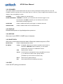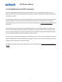
1
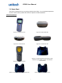
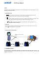
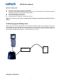
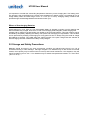
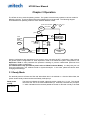
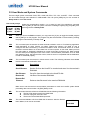
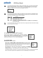
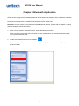
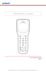
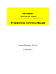
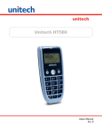
Unitech
HT630
User Manual Version 3
HT630 User Manual
NOTICE
This unit is equipped with a Li-ion battery pack. Battery power might be low
due to storage. Recharge the battery when required. For procedures on
how to charge the battery, please refer to Chapter 1.5 Quick Start.
Please switch on the backup battery and to ensure fully charge the
backup battery when you first time to use it.
i
HT630 User Manual
NOTICE .................................................................................................................................................... i
Chapter 1: Introduction.......................................................................................................................... 1
1.1 Overview .............................................................................................................................. 1
1.2 Support................................................................................................................................. 1
1.3 Customized HT630 .............................................................................................................. 1
1.4 Technical Specification ...................................................................................................... 3
1.5 Quick Start ........................................................................................................................... 5
1.6 Interface Ports ..................................................................................................................... 5
1.7 Using the Keyboard ............................................................................................................ 6
1.8 Triggering Scanner Module.................................................................................................. 7
1.9 Application Development Environment .............................................................................. 7
Chapter 2 Power System ........................................................................................................................ 8
2.1 Power System...................................................................................................................... 8
2.2 Power Low Indication ......................................................................................................... 8
2.3 Battery Replacement .......................................................................................................... 8
2.4 Recharging the Battery Pack ............................................................................................. 9
2.5 Storage and Safety Precautions ........................................................................................10
Chapter 3: Operation.............................................................................................................................. 11
3.1 Ready Mode ......................................................................................................................... 11
3.2 User Mode and System Commands .................................................................................. 12
3.3 Configure the Terminal in SET command ........................................................................ 13
3.4 Upload/Download by ESC Command ............................................................................... 15
Chapter 4 Built-in Application: FormCaching ..................................................................................... 16
4.1 Specification of FormCaching ........................................................................................... 16
4.2 How to Create a FormCaching........................................................................................... 17
4.3 How to Run FormCaching .................................................................................................. 17
4.4 Default Setting of FormCaching ........................................................................................ 17
Chapter 5 Bluetooth Application ..............................................................................18
HT630 User Manual
Chapter 1: Introduction
1.1 Overview
Thank you for choosing product from unitech Electronic Co. Ltd. The HT630, Portable Data
Collection Terminal, is one of the most versatile handheld computers in the market. It is DOS
compatible, capable of running programs, developed under C language. The HT630 has many prebuilt in functions and it is also self-programmable. In addition, it has a bundle Windows application,
capable to develop many applications, specifically for your business. The HT630 is light, weights
only 230 grams, has a large liquid crystal display (128 pixel X 64 pixel, capable of displaying 16*8 or
8*4 characters,) rugged, and water proof. It is also capable of withstand 1.2 meter multiple drops to
the concrete floor. With all these attributes, we believe the HT630 is going to satisfy your needs
totally. Depending on the model you had purchased, your terminal might be equipped with 3 different
memory (RAM) configuration, range from 512K, 2.5MB, 4.5MB and 8.5MB . HT630 also has offer 3
different optional communication/charging cradles. These are RS232, Ethernet and Modem cradles.
1.2 Support
Over here at unitech, making you satisfy is our first priority. If you find any problems regarding to this
terminal or any our other product please feel free to contact us at www.unitech-utp.com.tw —Asia,
www.ute.com —America, www.unitech-europe.nl —Europe, or www.unitech-adc.com —Global.
1.3 Customized HT630
It is highly likely when you receive this terminal; it has already been customized by the system
integrator or the system developer to meet your specific application. If this is the case, many
operating procedures, mentioned in this manual, may not apply. Please consult your system
provider for more information regarding to the customization.
1
HT630 User Manual
1.4 Technical Specification
Physical Characteristics
Dimensions:
165mm x 60mm x 35mm
Weight:
230g
Drop Specification: 1.2M multiple free drop to concrete floor
Display:
Battery:
128 x 64 pixel; 8 lines, 16 characters per line (small font) or 4 lines, 12 characters
(large font).
One 3.7V/900mAH Li-ion rechargeable battery;
Backup Battery:
One 120mAH Li-ion rechargeable battery
Environmental
Sealing:
Operating
Temperature:
Storage
Temperature
Humidity:
IP54
Electrostatic
Discharge (ESD)
Back-Lit Display:
4 KV for contact discharge
8 KV for air discharge
Yes
Keypads:
26 alphanumeric keys + one scan trigger (phosphorescent material)
-5C~50。C
-20C~70。C
5% to 95% RH, ; not condensed
Performance Characteristics
CPU:
X86 Compatible, 16 bit
Operating System:
DOS compatible
Memory:
Flash ROM
Application Development:
512KB/2.5MB/4.5MB/8.5MB(option)
256KB
C language, Turbo C, Visual C, JobGen plus (a window based
program generator), FormCaching (a built in program generator)
Communication
RS232; Modem, Ethernet serial communication
Operating Time
Over 12 hours at bar code scan per 5 sec
Symbologies
Buzzer
UPC/EAN, Code 39, Interleave 2 of 5, CODABAR, MSI, Code 128,
Code 93, Code 32,China Postal Code
Yes, over 70 dB
One LED
Dual color; Green for good; Red for bad
2
HT630 User Manual
1.5 Quick Start
This section is designed to let you quickly get familiar with HT630. If you need detail explanation
on some of the functions, please refer to further chapters for detail explanation.
HT630 Illustrations
Figure 0-1:HT630 front view
Figure 0-2 HT630 head view
Figure 0-4: HT630 side view
Figure 0-3: HT630 tail view
Figure 0-6: HT630 charging/communication cradle,
features 3 types: RS232, modem and Ethernet
communication
Figure 0-5: HT630 back view
Figure 0-7: Modem or Ethernet cradle back view
Figure 0-8: RS232 Cradle Back view
3
HT630 User Manual
Install Main Battery
1. Remove the battery door from the HT630 by moving the screw from battery cover.
2. Insert the battery into the main battery chamber by putting the head (2 point sticking out) into the
locking position first.
3. Reinstalled the battery door and tighten the screw on the battery door again.
Charging
Before using HT630, main battery and backup battery must be fully charged. The HT630 is equipped
with 3.7V 900m.A.H Lithium-Ion battery. When you first time to use the HT630 for the operation, please
ensure to fully charge the backup battery and main battery for at least 12 hours.
There are 2 ways to charge the main battery and backup battery:
1. Mount the unit on the cradle; connect power adaptor from the back of the cradle to any power outlet.
During charging, LED above power icon will be displayed red. Once it is fully charged, LED will be
turned to green.
2. Or, use the standard charging cable, which is packed with one of unitech HT630 packages or you
can order them separately, together with the power adaptor. Connect the power plug of the adaptor
to the charging cable, then, connect the charging cable to the main unit. Plug the power adaptor to
power outlet, the unit should be in charge. The charging is completed when LED light is shown on
green.
Important Note to be followed step by step for backup battery charging
Steps to be followed while you start to charge the backup battery
1. Please use any coin or suitable tool to open the main battery door.
Before you put the main battery inside, please be sure to switch on the backup battery.
2. Once you switch on the backup battery, then you can put the main battery to start to charge.
4
HT630 User Manual
Cradle
There are two ways to charge the main battery via the HT630 charging/communication cradle or a quick
charging /communication cable.
Cradle LED Icons
The icon indicates communication. When HT630 is transmitting data with the host
computer, LED will flash, showing that the data is transmitting.
The icon indicates the charging of the main unit. When the main battery is in charge on the
cradle, LED will be shown red; when fully charged, the light will turn to green.
This LED light shows the power status of the cradle itself. When the light is on, it is
indicated the cradle is powered on.
Power On
After charging completely, LED is turned to green and then, you are now ready to turn on the unit.
Press ( ☉) on the keypad to turn on the HT630!
Communication with the Host
RS232 Connection through
cable
RS232/Modem/Ethernet Communication
1. 6 Interface Ports
The HT630 does its’ communication via RS232 communication port located in the back of the unit. You
can connect the unit via the communication cable to PC RS232 jack for data transfer or connect through
cradle for communication.
5
HT630 User Manual
1.7 Using the Keyboard
The keypad of the HT630 consists of 27 rubber keys; the keyboard is configured into three different modes:
numeric mode, command mode, and alphabetic mode. All keys except ☉ key make sound (tone) when
pressed. Keys of upper four rows have larger size for easier key-pressing to input numbers.
[ ☉]
To turn on the unit, you need to press ☉ key. To turn off the unit, you will need to press and to
hold ☉ key for one second.
[CMD]
Press [CMD] key and the desire command key (located at the end of the keypad) to set the
keyboard to output command functions
[ESC]
In the Command or the Supervisor mode, press [ESC] key to get back to the pervious menu.
Numeric Mode
Press [Alpha]
Command
Mode
Press Command + the
desire command key
Laser trigger
Numeric
Command
Press [Alpha]
Alphabetic mode
Press Command + the
desire command key
Alpha
Figure 0-9: HT630 Keypad Legend
Numeric mode
The HT630 keyboard is initialized to normal mode after being powered on. In normal mode, the cursor is a
block and the keyboard is mainly used to input numeric data and use F1-F4 four function-keys.
COMMAND mode
Press [CMD] key to set the keyboard to command mode. In command mode, the cursor sign is still same
and the keyboard is mainly used to input special characters, make hot-key function, and use F5-F8 four
function-keys.
ALPHA mode
Press [ALPHA] key to toggle between normal mode keyboard and alpha mode keyboard. In the alpha
mode, the cursor is an underscore sign and the keyboard is available to input upper case letters. In the
alpha mode, every numeric key contains 3 characters individually. You need to press the key once to get
the first character, twice to get the second character and 3 times to get the third character. The characters
cycles back to the first character again.
For example:
First press [ALPHA] to switch the system to the alpha mode, the cursor type will be changed from block to
underscore
To enter ‘A’, press the key “A” once
To get “B”, press the same key twice
To get “C”, press the same key 3 times.
6
HT630 User Manual
1.8 Triggering Scanner Module
The HT630 can be used with a built-in integrated laser scanner module to input data. The built-in decoder
reads most barcode labels.
Users should keep laser window clean to prevent low reading rate of distorted bar code input signal.
1.9 Application Development Environment
The system of HT630 provides DOS functions and device drivers for application development, including bar
code decoding, keypad input, display output, serial input/output communication, real-time-clock access and
power management control.
The HT630 can be programmed by the high-level Windows-based JobGen Plus program generation
software or programmed by commonly used C compilers including Microsoft C, Borland C and Turbo C. An
executable program generated by JobGen Plus or created by a compiler is downloaded to the unit and run
on the unit.
JobGen Plus
The JobGen Plus is a Windows-based program generator that gives the user an ease-of-use and
comprehensive terminal application development environment. Through use-of-JobGen Plus, user can
design an application program for data collection terminal by simply drawing the data collection
sequence on paper, and thus, requires minimum programming skills.
For more detailed programming information, please refer to HT630 Programming Reference Manual,
JobGen Pro User's Manual.
7
HT630 User Manual
Chapter 2 Power System
2.1 Power System
Main Power
The terminal is operated by a rechargeable, 3.7V 900mAH rated Li-Ion, battery pack. The main battery
should be sufficient for daily operation up to 12 hours. (Base on 5 scan per second) However, since the
actual operation may be varied, it is possible to get the shorter result than our standard operation hours.
Backup Power
An onboard Lithium battery is used as the secondary power source to back up the data; the RTC (real time
clock chip) and RAM memory to prevent data-loss free environment.
Normally, the HT630 gets power from main power source to back-up RTC and RAM; also puts the Lithium
battery in standby state. When the main power source is removed or below the level to back-up the RAM
and RTC properly, the power circuit of the HT630 automatically switches to the Lithium battery for back-up.
It is recommended that the main battery can be always placed inside the unit with enough capacity for backup purpose in which case the Lithium battery can supply the power for up to half year before consuming all
its capacity up.
It is important to know that once the power in the backup battery used up, all data within the terminal will
be lost. So it is very important to backup all data when replacing backup battery.
2.2 Power Low Indication
Main Battery
When the main power source reaches the battery low condition, a warning
! WARNING!
message as right icon will be shown on the LCD when the HT630 is powered on or
MAIN BATTERY
a battery low icon sign will emerge on the right side of the LCD.
VOLTAGE LOW
When the main battery low occurs, the main battery can continue to supply power
for about 20 ~ 40 minutes per scan /5 second; however, the unit may reach the
system power cutoff point and automatically turn it off. Meanwhile, the unit continues to back up the data
contents in RTC and RAM; it cannot be powered up until the batteries have been recharged or replaced.
Lithium Backup Battery
When the Lithium backup battery doesn't have enough capacity to back up the
system, the message as right icon will be shown on LCD when the unit is powered
on. In this situation you should upload your data from the terminal immediately and
replace a new Lithium battery.
! WARNING!
Backup BATTERY
LOW
2.3 Battery Replacement
Main Battery
z
z
z
z
Make sure the unit is turned off.
Turn over the unit; unscrew the battery door lock screw by turning the screw left for quarter turn.
Slide the main battery pack from battery compartment.
Insert the new main battery into the socket.
8
HT630 User Manual
Remove battery pack
z
z
z
z
z
Remove the main battery as previously described.
Important! Once the backup battery is removed from the unit, all data within the unit will be lost, please
backup all files before you remove the backup battery.
Insert a new battery into the holder.
Put the backup battery cap back on.
Re-installed the main battery, cold star the new unit.
Make sure to back up your data in terminal before making the replacement the lithium back up
battery.
2.4 Recharging the Battery Pack
When the terminal shows “Main battery low” message, the battery needs to be recharged. Plug in the
power adaptor into a power outlet and connect the other end to the power outlet of the HT630, mount the
terminal into the cradle, LED light on the cradle will be in red, means in the charge. When the battery is
fully charged, LED light will be in green. This should take 2 to 3 hours.
Power
Outlet
Power Adaptor
Charging Consideration
9
HT630 User Manual
It is important to consider the surrounding temperature whenever you are charging the Li-Ion battery pack.
The process is the most efficient in the normal room temperature or slightly cooler. It is essential for you to
charge battery within the stated range of 32°F to 113°F (0°C to 45°C). Charging battery outside of the
specified range could damage batteries and shorten its life cycle.
Effects of Overcharging Batteries
Overcharging may occur when a Li-Ion rechargeable battery is charged in regular or quick charging rate
after it has been fully charged, but there is no risk of overcharging while charged in trickle charging rate.
A battery left to charge for several weeks may appear to have minimal capacity. This type of failure can be
remedied by temporarily depleting the battery of its power and recharging it to rejuvenate it. This condition
can be prevented by avoiding overcharging for a long period of time or always using the cradle to charge
the batteries of terminal. The cradle starts the charge process in the quick charge rate and switches to
trickle charging rate when it detects the battery is fully charged.
2.5 Storage and Safety Precautions
Batteries should be stored in an open environment condition and placed where there is no risk of
accidental shorting or other damage. Although charged Li-Ion batteries may be left unused for several
months, their capacity may be reduced due to back up and internal resistance. If this happens, they will
require recharging prior to use. Li-Ion batteries may be stored at temperatures between -4°F and 158°F
(-20°C to 70°C).
10
HT630 User Manual
Chapter 3 Operation
The HT630 is set up several operating modes. The system of terminal may operate in various modes for
different purposes. The figure below shows the operating flow of the terminal. The following diagram
summarized these operating modes to switch between different modes.
press and hold down CMD and
then press PWR
OFF
keys
press PWR
enter
program
name
then press
ENTER
APPLICATION
mode
HT630 V1.00
MEM 512KB
>
press CMD
(for two
seconds)
RUN
command
1.RUN
3.COM
5.ERA
7.CPY
press
press EXIT
2
<<START MENU>>
1.SUPERVISOR
2.WARM START
3.COLD START
press
1
then
2.TER
4.DIR
6.TYP
8.SET
Alpha
SUPERVISOR
mode
USER mode
System configurations are categorized in two groups, users can select “8.SET” command in User mode to
set general system configurations or enter Supervisor mode to set advanced system configurations. The
Supervisor mode is also protected with password checking to prevent unauthorized personnel from
changing the system configuration.
(For HT630 detail setup procedures please refer to HT630 Technical Binder). It is likely that your unit
came pre-configure by your software vender or system developer. In this case, please be caution when
changing these settings.
3.1 Ready Mode
The terminal performs a Power-On-Test and Warm-Start when it is switched on. After the Warm Start, the
system enters Ready mode and shows the Ready mode prompt.
Ready mode
prompt
HT630 Vx.xx
MEM 4608 KB
>
The first line indicates the model code and version number (e.g. V1.00). The second
line shows the size of the total installed RAM (i.e. 4608 KB). The third line prompts a
">" which indicates that the terminal passed the Power-on-test and is ready to be used.
11
HT630 User Manual
3.2 User Mode and System Commands
There are eight system commands: RUN, TER, COM, DIR, ERA, TYP, CPY, and SET. Each command
can be invoked through menu-selection in User mode. User can press [CMD] key for two seconds in
Ready mode to enter User mode.
User mode prompt
(1) RUN
(3) COM
(5) ERA
(7) CPY
(2) TER
(4) DIR
(6) TYP
(8) SET
Select the corresponding number, 1-8, or press [Å] and [Æ] to highlight a command
then hit [ENT] to select a system command. Pressing the [EXIT] key (hit [CMD], then
[ALPHA]) returns to Ready mode.
RUN
When you invoke the RUN command, you may press the [Æ] key to toggle the loaded program
and hit [ENT] to run the program. The program may also be executed on the terminal by entering
the program name directly in Ready mode.
TER
This command puts the terminal in either terminal emulation mode or FormCaching application
mode depending on which function you select. Please see chapter 4 for detail on how to
configure and use FormCaching. In terminal emulation mode, the terminal serves as a dumb
terminal to transmit data to or receive data from a Host computer. In this mode, data input from
bar code reader or keyboard is displayed on screen and output to RS-232 port. Data received
from the serial port is displayed on the LCD screen. Communication parameters, such as baud
rate, data bits, parity, stop bits and flow control, must be set to be compatible with the destination
in order to send data properly.
COM
This command puts the terminal in Kermit server mode. The following indicates the available
Kermit commands at the Host/PC side:
Command
Description
Send filename
Send a file from the Host/PC to terminal and store it in the terminal's
RAM disk
Get filename
Get a file from the terminal to the Host/PC disk
Remote dir
List files of the terminal RAM disk
Remote Del
filename
Delete a data file stored in the terminal RAM disk
Make sure to set the terminal communication parameters to match the host/PC system before
proceeding data communication. Hit [ESC] Ready mode.
DIR
This command shows the files in the RAM disk with the following information:
z
The list of file names stored in the RAM DISK
z
The size of program execution area
z
The amount of free RAM DISK space left
ERA
This command deletes a file from RAM disk of terminal. After the file has
been deleted, it can not be recovered.
< ERASE FILE >
SCAN.EXE
12
HT630 User Manual
TYP
This command dumps the content of a file on the terminal's LCD. The content of the file will be
displayed 128 (16 character x 8 line) characters at a time. Press any key to show the next
page or hit [CMD] then [ALPHA] keys to return to User mode prompt. If you try to display a
program or binary file, you may only see unintelligible characters.
< TYPE FILE >
SCAN.DAT
CPY
This command allows users to make copy of data from a source device to a destination device.
The source device may be a file, COM (serial input), CON (keyboard), and the destination device
may be a file, COM (serial output), CON (LCD display).
Source
file1
file1
file1
COM
CON
SET
Dest.
file2
COM
CON
file2
file2
Function
copy file1 to file2
output content of file1 to serial port
output content of file1 to LCD
input data from serial port and store in file2
input data from keyboard and store in file2, press [CMD] and then [ALPHA] key
to end the data input
This command allows users to set system date and time, assign laser feature and enable to display
power-on logo (see next section).
<SYSTEM SETUP>
1.DATE & TIME
2.SCANNER
3.DISPLAY
4.KEYPAD
5.BLUETOOTH
6.EXIT
3.3 Configure the Terminal in SET command
There are three categories of general system configuration available in
SET command. Select the corresponded number, 1-3, to set system
date/time, assign scanning feature and enable power-on Logo display. Hit
[CMD] then [ALPHA] keys to return to User mode prompt.
<SYSTEM SETUP>
1. DATE & TIME
2. SCANNER
3. DISPLAY
4. KEYPAD
5. BLUETOOTH
6. EXIT
3.3.1 DATE & TIME:
Setting system clock & calendar
When selects “1.DATE & TIME” in SET command menu, the screen as right
will be shown on the terminal LCD and let you set the system date and time of
Real Time Clock chip (RTC). The system date and time can be retrieved in
application and used as time stamp for data collection.
DATE-TIME
SETUP
1998/01/01
08:00:00
The second line shows the current date in the format YYYY/MM/DD
(year/month/day). If you want to reset the system date to January1 1997, then enter
[1][9][9][7],[0][1],[0][1]. Or press [ENT] key to skip the system date setting.
The third line shows the current time. The way to set system time is similar to set system date described
above. The format of system time is expressed in 24 hour of HH:MM:SS (hour:minute:second).
13
HT630 User Manual
3.3.2 SCANNER:
The system software of terminal decodes all major bar code symbologies including Code 39, Code 128,
Codabar, Code 93, I25, EAN, UPC, China Post code, etc. Use the [→] key to toggle among selection in each
category, then press [ENT] to confirm.
SCANNER
Enable / disable bar code decoding.
LASER TRIG MODE If NORMAL is selected, you must press and hold down trigger to scan
barcode label. If FLASH is selected, you can directly scan barcode
label without pressing trigger key.
LASER AIM
Enable / disable laser beam point target on a distance barcode.
VERIFICATION
Enable / disable double check scanned barcode.
3.3.3 DISPLAY:
Enable/disable power-on logo displays when power-on.
3.3.4 KEYPAD:
Allow user to set UPPER / LOWER case of character.
3.3.5 BLUETOOTH:
Allow user to send scanned barcode data to Bluetooth enabled computer or PDA.
BLUETOOTH
Enable / disable Bluetooth function.
BT SETUP
Config
BT MODE: Determine the mode of operation to be SLAVE or
MASTER. If MASTER mode is selected, you can enable
/disable auto connection to available BT devices.
Addr
Display the BT Address.
Search
Find BT devices and addresses, then press [ENT] to connect,
[→] to select the next BT access, [ESC] to leave.
(Available only when HT630 in master mode)
Reset
Restore factory default settings.
Exit
Leave the BLUETOOTH setting environment.
3.3.6 EXIT:
Leave the SET (setting) environment.
14
HT630 User Manual
3.4 Upload/Download by ESC Command
The way to upload/download by Kermit server described in section 3.2 will need the operator to set the
terminal to Kermit server mode by selecting user command “3.COM” in User mode or calling system function
in application program.
The hardware and software of terminal is designed that the unit can be woken up (turned on) by input from the
serial port. Besides, the terminal can also be instructed to process data communication by remote ESC
commands through built-in MULTI communication protocol. (Please refer to HT630 Technical Binder for detail
information)
After linking the terminal to a PC/host through RS232 interface, a communication program running on host
first sends a few of dummy bytes to the terminal and delays for about 500 mini-second to remotely wake up
the unit. Then, the program can be sent out a data pack of a remote ESC command that matches the MULTI
protocol to the terminal and instruct the terminal for certain process.
For instance, the terminal will automatically be executed the system routine to upload a file after receiving the
valid “File upload” ESC command. Meanwhile, the program running on the host should follow the control flow
of MULTI protocol and process to receive the data.
For detailed description of each ESC command and protocol, please see the HT630 Programming Reference
Manual.
15
HT630 User Manual
Chapter 4 Built-in Application- FormCaching
The system of terminal includes a built-in application, FormCaching. It allows you to create a data entry
application from specifying field prompt, type, length, input method and delimiter, etc. without writing
program and loading to the terminal.
4.1 Specification of FormCaching
DATA FIELD DEFINITION: maximum field number=8
Category
Range
Description
1 FIELD PROMPT max.16
set field prompting
characters
2 MIN/MAX
1-32
set minimum field length
DATA LENGTH
and maximum field length
3 DATA TYPE
1.NUMERIC
numeric data (0~9) or
2.ALPHANUM
alphanumeric data
(20H~FCH)
4 DEVICE TYPE
1.KEY ONLY
input by keyboard only,
2.SCAN ONLY
bar code scanning only or
3.BOTH
both
DATA RECORD DEFINITION
Category
Range
Description
5
BETWEEN
1.Append screen
specify to clear or append
FIELD
2.Clear screen
screen between two fields
6
FIELD
1.,
2.;
assign field delimiter
DELIMITER
3.Space
4.Tab
7
RECORD
1.CR 2.LF
assign record delimiter
DELIMITER
3.CRLF
8
DATE
1:NONE
specify format of Date
STAMP
2.YYYYMMDD
stamp
3.MMDD
FIELD
4.MMDDYYYY
5.DDMM
6.DDMMYYYY
9
TIME STAMP 1:NONE 2.HHMM
specify format of Time
FIELD
3.HHMMSS
stamp
10
FIELD
0-6
specify time delay
DELAY
between each record
input in second
16
HT630 User Manual
4.2 How to Create a FormCaching
FORMCACHING
1:YES
2:NO
OTHER:EXIT
You will need to enter Supervisor mode and select “4.FORM” category in order to set the configuration of
FormCaching (refer to the HT630 Programming Reference Manual for how to enter the Supervisor mode).
After selecting the “4.FORM” in Supervisor mode, the screen will show as above. The system will first ask
user to specify four categories of the field specification including field prompt, data length, data type and
device type of each data field. After completion to define all data fields, the user should hit [CMD] then
[ALPHA] keys to end the setup of field specification. This step also determines the number of fields in each
record and you may continue to set the rest six categories of record specification including between field,
field delimiter, record delimiter, date stamp field, time stamp field and field delay.
When the FormCaching application is executed, a data file named FORM.DAT will be created to store data.
The system will not allow the user to redefine FormCaching if the FORM.DAT is existed. It is necessary to
delete the FORM.DAT in order to change the configuration of FormCaching.
4.3 How to Run FormCaching
When FormCaching is enabled, the built-in application can be run by selecting “2.TER” command in User
mode and then select “2.FORMCACHING”. The FormCaching application will follow the setting as defined
to display prompting, get input and store data in the file named FORM.DAT. Hit [CMD] then [ALPHA] keys
to end FormCaching and return to system Ready mode. User may use [Å] key to browse a previous data
record, [Æ] key to step to next record, press [C] key to clear the record and then input new value of every
field of this record.
After collecting data, the FORM.DAT file can be uploaded to host either by invoking Kermit server in User
mode described in section 3.2 or remote ESC command described in 3.4.
4.4 Default Setting of FormCaching
In default, the FormCaching is initialized with settings as shown in the table below.
DATA FIELD SPECIFICATION: field number=2
Category
Setting
Field #1
FIELD PROMPT
ITEM:
DATA LENGTH
32
DATA TYPE
ALPHANUM
DEVICE TYPE
BOTH
Field #2 FIELD PROMPT
QTY:
DATA LENGTH
4
DATA TYPE
NUMERIC
DEVICE TYPE
KEY ONLY
DATA RECORD SPECIFICATION
Category
Setting
BETWEEN FIELD
FIELD DELIMITER
RECORD FELIMITER
DATE STAMP FIELD
TIME STAMP FIELD
FIELD DELAY
Append screen
,
CR
NONE
NONE
0
17
HT630 User Manual
Chapter 5 Bluetooth Application
HT630 can be configured to the standard Bluetooth HID as data output interface, which can allow the terminal
to send the scanned barcode data to Bluetooth enabled computer or PDA.
Follow the procedures below to establish a Bluetooth connection on the host.
Note: Make sure you power on the HT630 and enable Bluetooth function. (Please refer to Chapter 1.5 Quick
Start and Chapter 3.3.5 BLUETOOTH)
1. If your host has a built in Bluetooth function, enable the Bluetooth function.
If your host does not have the built in Bluetooth function, please attach an external Bluetooth dongle at
your host and install the driver.
2. Double-click the Bluetooth icon on the taskbar.
(As different user might use different brand of Bluetooth dongle, please find this according to your
dongle’s manual)
3. Click “View devices in rages” at My Bluetooth Places folder.
4. Right-click the HT630 icon and select “Pair Device”.
18
HT630 User Manual
5. A window pops up asking for PIN Code. Enter the default PIN Code “1234” and click OK button.
6. Right-click the HT630 icon and select “Discover Available Services”.
19
HT630 User Manual
7. Right-click the Dev B on HT630 icon and select “Connect to Bluetooth Serial Port”.
8. A pop-up window appears notifying you a serial port is automatically connected to HT630.
Click OK button.
20
HT630 User Manual
9. The icon turns to double arrows indicating the connected is ready.
Now you can run application or Windows Hyper Terminal on the host for testing.
21