1
Installation and service
instructions
VIESMANN
for contractors
Vitodens 200-W
Type B2HA, B2KA, 3.2 to 35 kW
Gas council no.
■ System boilers:
41-819-32; 41-819-33; 41-819-34; 41-819-35
■ Combi boilers:
47-819-28; 47-819-29; 47-819-30
For applicability, see the last page
VITODENS 200-W
5772 909 GB
11/2012
Please keep safe.
Safety instructions
Safety instructions
Please follow these safety instructions closely to prevent accidents and material losses.
Note
Details identified by the word "Note" contain additional information.
■ All current safety regulations as
defined by DIN, EN, DVGW, TRGI,
TRF, VDE and all locally applicable
standards
■ Gas Safety (Installation & Use) Regulations
– the appropriate Building Regulation
either the Building regulations, the
Building Regulation (Scotland), Building Regulations (Northern Ireland),
– the Water Fittings Regulation or
Water Bylaws in Scotland,
– the current I.E.E. Wiring Regulations.
Target group
If you smell gas
Danger
This symbol warns against the
risk of injury.
!
Please note
This symbol warns against the
risk of material losses and environmental pollution.
These instructions are exclusively intended for qualified contractors.
■ Work on gas installations must only be
carried out by a registered gas fitter.
■ Work on electrical equipment must
only be carried out by a qualified electrician.
■ The system must be commissioned by
the system installer or a qualified person authorised by the installer.
Regulations
Observe the following when working on
this system:
■ Statutory regulations regarding the
prevention of accidents
■ Statutory regulations regarding environmental protection
■ Codes of practice of the relevant trade
associations
2
Danger
Escaping gas can lead to explosions which may result in serious
injury.
■ Do not smoke. Prevent naked
flames and sparks. Do not
switch lights or electrical appliances on or off.
■ Close the gas shut-off valve.
■ Open windows and doors.
■ Evacuate any people from the
danger zone.
■ Notify your gas or electricity
supply utility from outside the
building.
■ Shut off the electricity supply to
the building from a safe place
(outside the building).
5772 909 GB
Safety instructions explained
Safety instructions
Safety instructions (cont.)
If you smell flue gas
Danger
The simultaneous operation of
the boiler and appliances that
extract air to the outside can
result in life threatening poisoning due to reverse flow of the flue
gas.
Fit an interlock circuit or take suitable steps to ensure a sufficient
supply of combustion air.
Danger
Flue gas can lead to life-threatening poisoning.
■ Shut down the heating system.
■ Ventilate the installation site.
■ Close all doors in the living
space.
Flue systems and combustion air
Working on the system
Ensure that flue systems are clear and
cannot be sealed, for instance due to
accumulation of condensate or other
causes. Ensure a sufficient supply of
combustion air.
Instruct system users that subsequent
modifications to the building characteristics are not permissible (e.g. cable/pipework routing, cladding or partitions).
Danger
Life-threatening poisoning
caused by carbon monoxide in
the flue gas occurs as a result of
leaking or blocked flue systems
or an insufficient supply of combustion air.
Ensure the flue system is in
proper working order. It must not
be possible to close apertures for
interconnected combustion air
supply.
5772 909 GB
Extractors
Operating appliances that extract air to
the outside (cooker hoods, extractors, air
conditioning units, etc.) can create negative pressure. If the boiler is operated at
the same time, this can lead to reverse
flow of the flue gas.
■ Where gas is used as the fuel, close
the main gas shut-off valve and safeguard it against unintentional reopening.
■ Isolate the system from the power supply (e.g. by removing the separate fuse
or by means of a mains isolator) and
check that it is no longer 'live'.
■ Safeguard the system against reconnection.
!
Please note
Electronic assemblies can be
damaged by electrostatic discharge.
Prior to commencing any work,
touch earthed objects, such as
heating or water pipes to discharge static loads.
Repair work
!
Please note
Repairing components that fulfil a
safety function can compromise
the safe operation of your system.
Defective components must be
replaced with genuine
Viessmann spare parts.
3
Safety instructions
Safety instructions (cont.)
Auxiliary components, spare and
wearing parts
Please note
Spare and wearing parts that
have not been tested together
with the system can compromise
its function. Installing non-authorised components and making
non-approved modifications or
conversions can compromise
safety and may invalidate our
warranty.
For replacements, use only original spare parts supplied or
approved by Viessmann.
5772 909 GB
!
4
Index
Index
Installation instructions
Preparing for installation
Intended use.........................................................................................................
Product information..............................................................................................
Preparing for installation.......................................................................................
7
7
8
Installation sequence
Fitting the boiler and making connections............................................................
Flue gas connection.............................................................................................
Condensate connection........................................................................................
Gas connection....................................................................................................
Opening the control unit casing............................................................................
Electrical connections...........................................................................................
Closing the control unit casing and inserting the programming unit.....................
Fitting the front panel............................................................................................
11
12
13
14
15
16
25
26
Service instructions
5772 909 GB
Commissioning, inspection, maintenance
Steps - commissioning, inspection and maintenance.......................................... 27
Further details regarding the individual steps....................................................... 29
Code 1
Calling up coding level 1......................................................................................
"General"/group 1.................................................................................................
"Boiler"/group 2....................................................................................................
"DHW"/group 3.....................................................................................................
"Solar"/group 4.....................................................................................................
"Heating circuit ..."/group 5...................................................................................
60
61
64
64
65
67
Code 2
Calling up coding level 2......................................................................................
"General"/group 1.................................................................................................
"Boiler"/group 2....................................................................................................
"DHW"/group 3.....................................................................................................
"Solar"/group 4.....................................................................................................
"Heating circuit ..."/group 5...................................................................................
73
74
82
84
86
91
Diagnosis and service scans
Service level......................................................................................................... 100
Diagnosis.............................................................................................................. 101
Checking outputs (actuator test).......................................................................... 107
5
Index
Index (cont.)
Troubleshooting
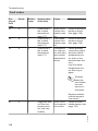
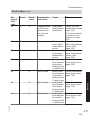
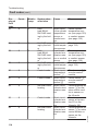
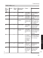
Fault display......................................................................................................... 110
Fault codes........................................................................................................... 112
Repairs................................................................................................................. 129
Function description
Constant temperature control unit........................................................................ 139
Weather-compensated control unit...................................................................... 140
Internal extensions (accessories)......................................................................... 142
External extensions (accessories)........................................................................ 144
Control functions.................................................................................................. 148
Allocating heating circuits to the remote control................................................... 156
Electronic combustion control unit........................................................................ 156
Designs
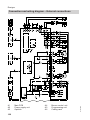
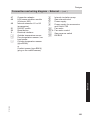
Connection and wiring diagram – Internal connections ...................................... 158
Connection and wiring diagram – External connections...................................... 160
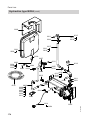
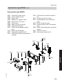
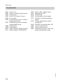
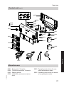
Parts lists
Ordering individual parts...................................................................................... 162
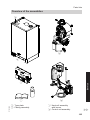
Overview of the assemblies................................................................................. 163
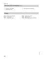
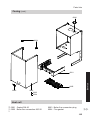
Casing.................................................................................................................. 164
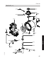
Heat cell............................................................................................................... 165
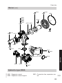
Burner................................................................................................................... 168
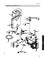
Hydraulics type B2HA.......................................................................................... 169
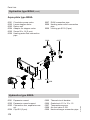
Hydraulics type B2KA........................................................................................... 172
Control unit........................................................................................................... 176
Miscellaneous....................................................................................................... 177
Commissioning/service reports........................................................................ 179
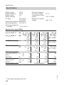
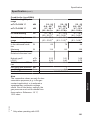
Specification....................................................................................................... 180
Certificates
Declaration of conformity...................................................................................... 182
Manufacturer's certificate according to the 1st BImSchV [Germany]................... 182
5772 909 GB
Keyword index.................................................................................................... 183
6
Preparing for installation
Intended use
Intended usage presupposes that a fixed
installation in conjunction with permissible, system-specific components has
been carried out.
Any usage beyond this must be
approved by the manufacturer for the
individual case.
Incorrect usage or operation of the appliance (e.g. the appliance being opened
by the system user) is prohibited and
results in an exclusion of liability. Incorrect usage also occurs if the components
in the heating system are modified from
their intended function (e.g. if the flue
gas and ventilation air paths are
sealed).
Commercial or industrial usage for a purpose other than heating the building or
DHW does not comply with regulations.
Product information
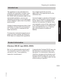
Vitodens 200-W, type B2HA, B2KA
In principle the Vitodens 200-W may only
be delivered to countries listed on the
type plate. For deliveries to alternative
countries, an approved contractor must
arrange individual approval on his own
initiative and in accordance with the law
of the country in question.
5772 909 GB
Set up for operation with natural gas E.
For conversion to LPG P (without conversion kit), see "Commissioning,
inspection, maintenance".
7
Installation
The appliance is only intended to be
installed and operated in sealed unvented heating systems that comply with
EN 12828, with due attention paid to the
associated installation, service and
operating instructions. It is only designed
for the heating of water that is of potable
water quality.
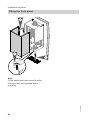
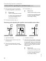
Preparing for installation
Preparing for installation
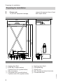
!
Please note
To prevent equipment damage,
connect all pipework free of load
and torque stress.
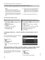
450
100
215
50
G
360
850
1925 H
730
a
A Heating flow Rp¾
B DHW Rp½ (combi boilers)
Cylinder flow G¾ (system boiler)
C Gas connection
D Cold water Rp½ (combi boilers)
Cylinder return G¾ (system boiler)
8
K
E
F
G
H
K
Heating return Rp¾
Filling/draining
Wiring area
Min. clearances below the boiler
Condensate drain
5772 909 GB
A B C D EF
Preparing for installation
Preparing for installation (cont.)
Dim. a
mm
136
158
158
Note
This boiler (IP rating: IP X4D) is
approved for installation in wet rooms
inside safety zone 1 in accordance with
IEEE Wiring Regulations, providing the
occurrence of hosed water can be ruled
out.
Observe the IEEE Wiring Regulations.
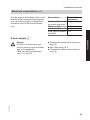
1. Fit the supplied pre-plumbing jig or
mounting frame at the installation
location.
2. Prepare the connections on the water
side to the valves on the pre-plumbing jig or mounting frame.
Thoroughly flush the heating system.
3. Prepare the gas connection according to TRGI or TRF [or local regulations].
4. Prepare the electrical connections.
■ Power cable: NYM-J 3 x 1.5 mm2,
fuse max. 16 A, 230 V, 50 Hz.
■ Accessory cables: NYM with the
required number of conductors for
the external connections.
■ All cables should protrude
1200 mm from the wall near "G".
Pre-plumbing jig or mounting
frame installation instructions.
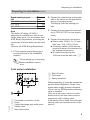
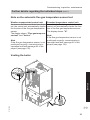
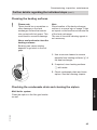
Cold water installation
5772 909 GB
F Shut-off valve
G Cold water
H Safety assembly
A
B
C
D
E
Cold water connection, boiler
Drain
Visible discharge pipe outlet point
Safety valve
Non-return valve
Safety assembly H must be installed as
per the Water Regulation Guide if the
mains water supply pressure exceeds
10 bar, and no DHW pressure reducing
valve is installed.
Only use a non-return valve or a combined shut-off and non-return valve in
conjunction with a safety valve.
If the safety valve is used, the cold water
shut-off valve on the boiler must not be
shut off.
9
Installation
Rated heating output
kW
3.2 - 19.0
6.5 - 26.0
8.8 - 35.0
Preparing for installation
Preparing for installation (cont.)
Remove the toggle on the cold water
shut-off valve (if installed) to prevent
anyone shutting it off manually.
Shock arrestor
5772 909 GB
If draw-off points that could cause pressure peaks (water hammer/shock) are
connected to the same pipework as the
boiler (such as pressure washers, washing machines or dishwashers), we would
recommend the installation of a shock
arrestor near the source of such pressure shocks.
g: Fit a small domestic expansion vessel if water hammer occurs.
10
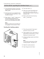
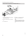
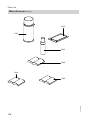
Installation sequence
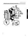
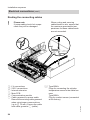
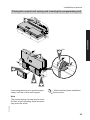
Fitting the boiler and making connections
6.
Installation
2.
4.
7.
5.
1.
2x
2x
5772 909 GB
3.
11
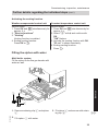
Installation sequence
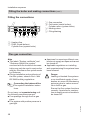
Fitting the boiler and making connections (cont.)
Fitting the connections
C Gas connection
D Cold water (combi boilers)
Cylinder return (system boiler)
E Heating return
F Filling/draining
A B C D
EF
A Heating flow
B DHW (combi boilers)
Cylinder flow (system boiler)
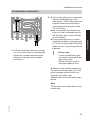
Flue gas connection
Note
■ The labels "System certificate" and
"Skoberne GmbH flue system"
enclosed with the technical documentation may only be used in conjunction
with the Viessmann flue system made
by Skoberne.
■ During installation and positioning of
the flue system, observe Part J and
BS 5440 building regulations.
Connecting the balanced flue
Flue system installation instructions.
Danger
Leaking or blocked flue systems
or an insufficient supply of combustion air cause life threatening
poisoning due to carbon monoxide in the flue gas.
Ensure the flue system functions
correctly. Apertures for combustion air supply must not be able to
be closed off.
5772 909 GB
Do not carry out commissioning until
the following conditions are met:
■ Free passage through the flue gas
pipes.
■ Flue system with positive pressure is
gas-tight.
■ Apertures for ensuring sufficient combustion air supply are open and cannot
be closed off.
■ Applicable regulations on installing
and commissioning flue systems have
been followed.
12
Installation sequence
2. ■ The condensate pipe is connected
with the discharge pipe of the
safety valve. The condensate hose
supplied meets the temperature
requirements that are part of the
CE certification.
■ We recommend the internal connection of the condensate pipe to
the domestic drain, either directly
or via a tundish.
■ If the condensate pipe is routed
outside the building, use a pipe with
7 30 mm at least, and protect this
pipe from frost. Avoid long external
pipelines.
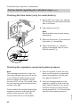
1. Pull the condensate hose far enough
out of the boiler that no unnecessary
bends are created inside the boiler.
Check the tightness of the siphon
connection.
!
Please note
Frozen condensate pipes
can result in faults and damage to the boiler.
Always insulate condensate pipes against frost.
■ Observe local building regulations.
Connect condensate pipe A to the
public sewage system with a constant fall and a pipe vent.
Observe the local waste water regulations.
5772 909 GB
Note
Fill the siphon with water before commissioning.
13
Installation
Condensate connection
Installation sequence
Gas connection
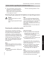
3. Vent the gas line.
Conversion to other gas types:
Service instructions (details for
converting to LPG are on page
35)
A
1. Seal gas shut-off valve A into the
gas supply pipe.
2. Carry out a tightness test.
Note
Only use suitable and approved leak
detection agents (EN 14291) and
devices for the tightness test. Leak
detection agents with unsuitable constituents (e.g. nitrites, sulphides) can
cause material damage.
Remove residues of the leak detection agent after testing.
Please note
Excessive test pressure may
damage the boiler and the gas
valve.
Max. test pressure 150 mbar.
Where higher pressure is
required for tightness tests,
disconnect the boiler and the
gas valves from the gas supply pipe (undo the fitting).
5772 909 GB
!
14
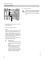
Installation sequence
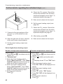
Opening the control unit casing
!
Please note
Electronic assemblies can be
damaged by electrostatic discharge.
Before beginning work, touch
earthed objects, such as heating
or water pipes, to discharge static
loads.
2.
2x
Installation
3.
1.
5.
4x
5772 909 GB
4.
15
5772 909 GB
5
16
1
2 1 5 4 32 1
145
145
2
100
35
28
20
96
40
96
A
40
230V~ 230V~
N L1 L N
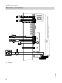
Installation sequence
Electrical connections
A Jumper
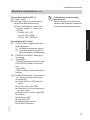
Installation sequence
Electrical connections (cont.)
Information on connecting
accessories
When connecting accessories
observe the separate installation
instructions provided with them.
Installation
Connections at plug 230 V~
fÖ Power supply
lH ■ Power supply for accessories
■ External demand/blocking
■ Room temperature control unit
(remove jumper A when connecting):
– Vitotrol 100, UTA
– Vitotrol 100, UTDB
– Vitotrol 100, UTDB-RF
5772 909 GB
Connections at LV plug
X3 Plug X3 can be removed to facilitate installation.
! Outside temperature sensor
? Flow temperature sensor for
low loss header (accessories)
X4 KM BUS connection, heating circuit pump
% Type B2HA:
Cylinder temperature sensor (part
of the DHW cylinder connection
set)
Type B2KA:
Comfort sensor (connected at the
factory)
aVG KM BUS subscriber (accessories)
To connect several accessories,
see page 22.
■ Vitotrol 200A or 300A remote
control
■ Vitocom 100, type GSM
■ Extension kit for one heating circuit with mixer
■ Solar control module, type SM1
■ Vitosolic
■ Extension AM1
■ Extension EA1
■ Wireless base station
■ KM BUS distributor
17
Installation sequence
Electrical connections (cont.)
Outside temperature sensor !
For fitting the wireless outside temperature sensor (wireless accessory):
Wireless base station installation
and service instructions
Fitting location for outside temperature sensor
■ Not immediately below balconies or
gutters
■ Never render over
Outside temperature sensor connection
2-core lead, length max. 35 m with a
cross-section of 1.5 mm2
■ North or north-western wall, 2 to
2.5 m above ground level; in multi
storey buildings, in the upper half of
the second floor
■ Not above windows, doors or vents
External demand via switching contact
Connection options:
■ Extension EA1 (accessory, see separate installation instructions).
■ Plug lH.
Please note
'Live' contacts lead to short circuits or phase failure.
The external connection must be
potential-free and comply with
the requirements of safety category II.
5772 909 GB
Burner operation is load-dependent if the
contact is closed. The boiler water is
heated to the value set in coding address
"9b" in group "General"/1. The boiler
water temperature is limited by this set
value and the electronic maximum limit
(coding address "06" in group "Boiler"/
2).
!
18
Installation sequence
Electrical connections (cont.)
Plug lH
Extension EA1
B
A
1 L?N
DE
[{A
DE
[{S
DE
[{D
lH
A Floating contact (when connecting,
remove jumper across L and 1)
Codes
■ "4b:1" in group "General"/1.
■ Effect of the function on the relevant
heating circuit pump:
Coding address "d7" in group "Heating
circuit" (only with weather-compensated control units).
■ Effect of the function on the circulation
pump for cylinder heating (if installed):
Coding address "5F" in group "DHW"/
3.
Installation
A
A Floating contact
B Extension EA1
Codes
■ Set "3A" (DE1), "3b" (DE2) or "3C"
(DE3) in group "General"/1 to 2.
■ Effect of the function on the relevant
heating circuit pump:
Coding address "d7" in group "Heating
circuit" (only with weather-compensated control units).
■ Effect of the function on the circulation
pump for cylinder heating (if installed):
Coding address "5F" in group "DHW"/
3.
External demand via 0 – 10 V input
5772 909 GB
Connection at 0 – 10 V input to extension EA1.
Ensure DC separation between the earth
conductor and the negative pole of the
on-site voltage source.
19
Installation sequence
Electrical connections (cont.)
0-10V
[{{]
aBJ
+-
SÖ P
A
f-]
fÖ
0 – 1 V ≙ No default set boiler water
temperature
1V
≙ Set value 10 °C
10 V
≙ Set value 100 °C
L?N N?L
230 V~
U
0-10 V
+
External blocking via switching contact
Connection options:
■ Plug lH.
■ Extension EA1 (accessory, see separate installation instructions).
Please note
'Live' contacts lead to short circuits or phase failure.
The external connection must be
potential-free and comply with
the requirements of safety category II.
5772 909 GB
The burner is switched off if this contact
is closed. The heating circuit pump and
(if installed) the circulation pump for cylinder heating are switched according to
the set code (see following table
"Codes").
!
20
Installation sequence
Electrical connections (cont.)
Plug lH
Extension EA1
A
1 L?N
DE
[{A
DE
[{S
B
DE
[{D
lH
A Floating contact (when connecting,
remove jumper across L and 1)
A Floating contact
B Extension EA1
Codes
■ Set "3A" (DE1), "3b" (DE2) or "3C"
(DE3) in group "General"/1 to 3 or 4.
■ Effect of the function on the heating circuit pump:
Coding address "d6" in group "Heating
circuit" (only with weather-compensated control units).
■ Effect of the function on the circulation
pump for cylinder heating (if installed):
Coding address "5E" in group "DHW"/
3.
5772 909 GB
Codes
■ "4b:2" in group "General"/1
■ Effect of the function on the heating circuit pump:
Coding address "d6" in group "Heating
circuit" (only with weather-compensated control units).
■ Effect of the function on the circulation
pump for cylinder heating (if installed):
Coding address "5E" in group "DHW"/
3.
Installation
A
21
Installation sequence
Electrical connections (cont.)
Power supply for accessories at plug lH (230 V~)
Where the boiler is installed in a wet
area, the power supply connection for
accessories must not be made at the
control unit. If the boiler is installed outside wet areas, then the power supply
connection for accessories can be made
directly at the control unit. This connection is switched directly with the ON/OFF
switch of the control unit.
If the total system current exceeds 6 A,
connect one or more extensions via an
ON/OFF switch directly to the mains supply (see next chapter).
Connection of accessories
Power supply and KM BUS
Power supply to all accessories via heat source control unit
40 A
40
D
145
145
40 A
40
C
145
145
40 A
40
B
145
145
40
96
145
A
E
Some accessories with direct power supply
145
145
40 A
40
40 A
40
D
C
145
145
40 A
40
B
145
145
40
96
145
A
E
22
D Extension AM1, EA1 and/or solar
control module, type SM1
E ON/OFF switch
5772 909 GB
A Heat source control unit
B Extension kit for heating circuit with
mixer M2
C Extension kit for heating circuit with
mixer M3
Installation sequence
Electrical connections (cont.)
A buffer relay must be fitted if the current
flowing to the connected working parts
(e.g. circulation pumps) is higher than
the safety level of the relevant accessory.
Accessories
Internal fuse
protection
Extension kit for heat- 2 A
ing circuit with mixer
Extension AM1
4A
Extension EA1
2A
Solar control module, 2 A
type SM1
■ Remove the existing test wires from
plug fÖ.
■ Max. fuse rating 16 A.
■ Connect the mains power supply to
plug fÖ.
5772 909 GB
Danger
Incorrect core allocation can
result in serious injury and damage to the appliance.
Take care not to interchange
wires "L1" and "N".
23
Installation
Power supply fÖ
Installation sequence
Electrical connections (cont.)
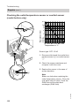
Routing the connecting cables
!
Please note
If power cables touch hot components they will be damaged.
When routing and securing
cables/leads on site, ensure that
the maximum permissible temperatures for these cables/leads
are not exceeded.
F
5
E
A
D
B
C
24
LV connections
230 V connections
Internal extension
Main PCB
Communication module
Cable grommet for power cable
Remove the existing cable grommet
when using larger cross-sections
(up to 7 14 mm). Secure the cable
with cable grommet F (white).
% Type B2HA:
Plugs for connecting the cylinder
temperature sensor to the cable harness
Type B2KA:
Plug for comfort sensor (connected
at the factory)
5772 909 GB
A
B
C
D
E
F
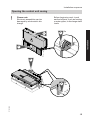
Installation sequence
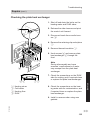
Closing the control unit casing and inserting the programming unit
3.
Installation
1.
2x
2.
6.
5.
4.
Insert programming unit (packed separately) into the control unit support.
Wall mounting base installation
instructions
5772 909 GB
Note
The programming unit can also be inserted into a wall mounting base (accessories) near the boiler.
25
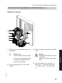
Installation sequence
Fitting the front panel
2.
3.
1.
2x
5772 909 GB
Note
Fit the safety guard and ensure that the
locking screws are tightened before
operating.
26
Commissioning, inspection, maintenance
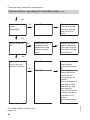
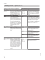
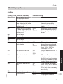
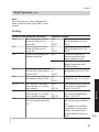
Steps - commissioning, inspection and maintenance
For further information regarding the individual steps, see the page indicated
Commissioning steps
Inspection steps
Maintenance steps
•
•
•
•
1. Checking the power supply
2. Filling the heating system.............................................. 29
3. Switching on the mains voltage and ON/OFF switch
4. Language selection – only for weather-compensated
control units.................................................................... 30
•
5. Setting the time and date - only for weathercompensated control units and for timer controlled
constant temperature units........................................... 30
•
6. Note on the automatic flue gas temperature sensor
test................................................................................... 31
•
•
•
•
7. Venting the boiler........................................................... 31
8. Venting the heating system........................................... 32
9. Filling the siphon with water......................................... 33
•
•
•
•
•
•
•
•
•
11. Designating heating circuits - only for weathercompensated control units............................................ 34
•
12. Checking the gas type.................................................... 34
•
14. Checking the static and supply pressure..................... 35
13. Gas type conversion (only for operation with LPG).... 35
•
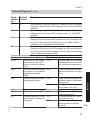
15. Function sequence and possible faults....................... 37
16. Max. heating output setting........................................... 39
17. Tightness test for balanced flue system (annular gap
check).............................................................................. 39
•
•
5772 909 GB
10. Checking all connections on the heating water side
and DHW side for leaks
•
•
18. Burner removal .............................................................. 40
19. Checking the burner gasket and burner gauze
assembly......................................................................... 41
27
Service
•
Page
Commissioning, inspection, maintenance
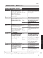
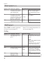
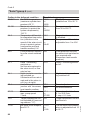
Steps - commissioning, inspection and… (cont.)
Commissioning steps
Inspection steps
Maintenance steps
•
•
20. Checking and adjusting the ignition and ionisation
electrodes........................................................................ 42
21. Cleaning the heating surfaces....................................... 43
•
•
•
23. Fitting the burner............................................................ 45
•
•
•
•
•
•
•
•
•
•
•
30. Checking the combustion quality................................. 47
•
•
•
•
•
32. Checking the external LPG safety valve (if installed)
•
•
•
•
•
•
•
•
•
•
•
22. Checking the condensate drain and cleaning the
siphon.............................................................................. 43
24. Checking the neutralising system (if installed)
25. Checking the flow limiter (only for combi boilers)...... 46
26. Checking the expansion vessel and system pressure 46
27. Checking the function of safety valves
28. Checking firm seating of electrical connections
29. Checking all gas equipment for tightness at operating
pressure........................................................................... 47
31. Checking the flue system for unrestricted flow and
tightness
33. Matching the control unit to the heating system......... 49
34. Adjusting the heating curves (only for weathercompensated control units)........................................... 54
•
35. Connecting the control unit to the LON system - only
for weather-compensated control units....................... 57
•
36. Calling up and resetting the service display................ 59
37. Instructing the system user........................................... 59
5772 909 GB
•
Page
28
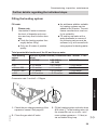
Commissioning, inspection, maintenance
Further details regarding the individual steps
Filling the heating system
Fill water
!
■ An antifreeze additive suitable
for heating systems can be
added to the fill water. The antifreeze manufacturer must verify its suitability.
■ Fill and top-up water with a
water hardness in excess of
the following values must be
softened, e.g. with a small softening system for heating water.
Please note
Unsuitable fill water increases
the level of deposits and corrosion and may lead to boiler damage.
■ Flush the heating system thoroughly before filling.
■ Only use fill water of potable
quality.
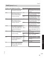
Total permissible hardness of the fill and top-up water
Total heating
Specific system volume (Conversion rate 1 mol/m3 = 100
output
ppm)
kW
< 20 l/kW
≥ 20 l/kW to
≥ 50 l/kW
< 50 l/kW
≤ 50
≤ 3.0 mol/m3
≤ 2.0 mol/m3
< 0.02 mol/m3
3
3
> 50 to ≤ 200
≤ 2.0 mol/m
≤ 1.5 mol/m
< 0.02 mol/m3
3
3
> 200 to ≤ 600
≤ 1.5 mol/m
≤ 0.02 mol/m
< 0.02 mol/m3
3
3
> 600
< 0.02 mol/m
< 0.02 mol/m
< 0.02 mol/m3
Conversion rate 1 mol/m3 = 100ppm
Service
A
5772 909 GB
1. Check the pre-charge pressure of the
expansion vessel. See page 46.
2. Close the gas shut-off valve.
3. Fill the heating system via boiler drain
& fill valve A in the heating return (at
the connection set or on site - minimum system pressure > 1.0 bar) or
via a suitable filling loop.
29
Commissioning, inspection, maintenance
Further details regarding the individual steps (cont.)
Note
If the control unit has not been
switched on prior to filling the system,
then the servomotor of the diverter
valve will still be in its central position,
and the system will be completely filled.
4. If the control unit had already been
switched on before filling began:
Switch control unit ON and activate
filling function (see next chapter).
5. Close boiler drain & fill valve A.
Activating the filling function
Weather-compensated control unit
Service menu
1. Press OK and å simultaneously for
approx. 4 s.
2. "Service functions"
3. "Filling"
Filling function is enabled.
4. Ending filling function:
Press OK or ä.
Constant temperature control unit
Service menu
1. Press OK and å simultaneously for
approx. 4 s.
2. Select "4" and confirm with OK.
"ON" flashes.
3. Activate the filling function with OK.
"bF on" is shown constantly.
4. Ending filling function:
Press ä.
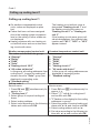
Language selection – only for weather-compensated control
units
At the commissioning stage, the display
is in German (factory setting).
Extended menu:
1. å
2. "Einstellungen"
3. "Sprache"
4. Select the required language with
/ .
Sprache
Deutsch
ç
DE ê
Bulgarski
BG ê
Cesky
CZ ê
Dansk
DK ê
Wählen mit
(
The time and date need to be reset during commissioning or after a prolonged
time out of use.
30
Extended menu:
1. å
2. "Settings"
3. "Time / Date"
4. Set current time and date.
5772 909 GB
Setting the time and date - only for weather-compensated control
units and for timer controlled constant temperature units
Commissioning, inspection, maintenance
Further details regarding the individual steps (cont.)
Note on the automatic flue gas temperature sensor test
Weather-compensated control unit
As soon as the time and date have been
set, the control unit automatically checks
the function of the flue gas temperature
sensor.
The display shows: "Flue gas temp sensor test" and "Active".
Note
If the flue gas temperature sensor is not
positioned correctly, commissioning is
cancelled and fault message A3 is displayed (see page 135).
Constant temperature control unit
Immediately after being switched on, the
control unit automatically checks the function of the flue gas temperature sensor.
The display shows: "A".
Note
If the flue gas temperature sensor is not
positioned correctly, commissioning is
cancelled and fault message A3 is displayed (see page 135).
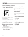
Venting the boiler
Service
B
5772 909 GB
A
31
Commissioning, inspection, maintenance
Further details regarding the individual steps (cont.)
1. Close the shut-off valves on the heating water side. If required, remove the
safety guard.
2. Push the drain hose (supplied inside
the appliance) onto top valve B and
connect to a drain.
3. Open valves A and B and vent at
mains pressure (purge) until no
sound of escaping air can be heard
and no more air bubbles are visible.
4. First close valve B.
5. When the required operating pressure has built up, close valve A.
Open the shut-off valves on the heating water side.
6. Remove the drain hose from top
valve B and retain.
Note
Note the system pressure at the pressure gauge. Do not exceed 1.5 bar.
Venting the heating system
1. Close the gas shut-off valve and
switch the control unit ON.
2. Check whether the air vent screw on
quick-action air vent valve A of the
heating circuit pump is open.
3. Activate venting program (see following steps).
A
Note
For function and sequence of the
venting program, see page 150.
4. Adjust the system pressure.
5772 909 GB
5. Open the gas shut-off valve.
32
Commissioning, inspection, maintenance
Further details regarding the individual steps (cont.)
Activating the venting function
Weather-compensated control unit
Service menu
1. Press OK and å simultaneously for
approx. 4 s.
2. "Service functions"
3. "Venting"
Venting function is enabled.
4. Ending venting function:
Press OK or ä.
Constant temperature control unit
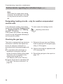
Service menu
1. Press OK and å simultaneously for
approx. 4 s.
2. Select "5" with Ú and confirm with
OK.
"ON" flashes.
3. Activate the venting function with OK.
"EL on" is shown constantly.
4. Ending venting function:
Press ä.
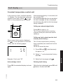
Filling the siphon with water
Service
Multi boiler system:
Fill the siphon in the flue gas header with
water as well.
A
B
5772 909 GB
1. Remove retaining clip A and siphon
B.
3. Fit siphon B and secure with retaining clip A.
2. Fill siphon B with water.
33
Commissioning, inspection, maintenance
Further details regarding the individual steps (cont.)
Note
Never twist the supply hose during
assembly. Route the drain hose without any bends and with a constant
fall.
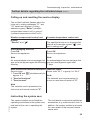
Designating heating circuits - only for weather-compensated
control units
In the delivered condition, the heating
circuits are designated "Heating circuit
1", "Heating circuit 2" and "Heating
circuit 3" (if installed).
If the system user prefers, the heating
circuits can be designated differently to
suit the specific system.
To enter names for heating circuits:
Operating instructions
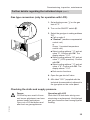
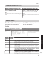
Checking the gas type
1. Determine the gas type and Wobbe
index by asking your local gas supply
utility or LPG supplier.
2. Convert the burner for operation with
LPG (see page 35).
3. Record the gas type in the report on
page 179.
5772 909 GB
The boiler is equipped with an electronic
combustion controller that adjusts the
burner for optimum combustion in
accordance with the prevailing gas quality.
■ For operation with natural gas no
adjustment is therefore required
across the entire Wobbe index range.
The boiler can be operated in the
Wobbe index range 9.5 to
15.2 kWh/m3 (34.2 to 54.7 MJ/m3).
■ Convert the burner for operation with
LPG (see "Gas type conversion" on
page 35).
34
Commissioning, inspection, maintenance
Further details regarding the individual steps (cont.)
Gas type conversion (only for operation with LPG)
1. Set adjusting screw A on the gas
train to "2".
1
A
2. Turn on the ON/OFF switch 8.
2
3. Select the gas type in coding address
"82":
■ Call up code 2
■ "General" (weather-compensated
control unit)
or
Group 1 (constant temperature
control unit).
■ Select coding address "11" and set
value "9". Confirm with OK. The
display shows "11:0".
■ Select coding address "82" and set
value "1" (LPG operation). Confirm
with OK.
■ Select coding address "11" and set
value ≠ "9". Confirm with OK. The
display shows "11:0".
■ End service functions.
5. Affix label "G31" (supplied with the
technical documentation) adjacent to
the type plate on the cover panel.
Checking the static and supply pressure
Operation with LPG
Flush the LPG tank twice during commissioning or replacement. Vent the tank
and gas connection line thoroughly after
flushing.
5772 909 GB
Danger
CO build-up as a result of incorrect burner adjustment can have
serious health implications.
Carry out a CO test before and
after work on gas appliances.
35
Service
4. Open the gas shut-off valve.
Commissioning, inspection, maintenance
Further details regarding the individual steps (cont.)
6. Check the supply (flow) pressure.
A
Set value:
■ Natural gas: 20 mbar
■ LPG: 37 mbar
Note
■ Use a suitable measuring device
with a resolution of at least
0.1 mbar to check the supply pressure.
■ The pressure drop between the
gas tap and gas valve is 0.5 mbar
at full load.
1. Close the gas shut-off valve.
2. Undo screw A in test nipple "IN" on
the gas train but do not remove it, and
connect the pressure gauge.
3. Open the gas shut-off valve.
4. Check the static pressure and record
the actual value in the report on
page 179.
Set value: max. 57.5 mbar
5. Switch on mains voltage and start the
boiler.
8. Shut down the boiler, close the gas
shut-off valve, remove the pressure
gauge and close test nipple A with
the screw.
9. Open the gas shut-off valve and start
the appliance.
Danger
Gas escaping from the test
nipple leads to a risk of explosion.
Check gas tightness at test
nipple A.
5772 909 GB
Note
During commissioning, the boiler can
enter a fault state (fault EE is shown)
because of air in the gas line. After
approx. 5 s press reset button R to
reset the burner.
7. Record the actual value in the report
on page 179.
Take the action shown in the following table.
36
Commissioning, inspection, maintenance
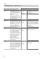
Further details regarding the individual steps (cont.)
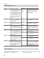
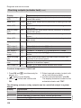
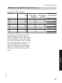
Supply pressure (flow pressure)
For natural gas
For LPG
Below 17.4 mbar
Below 25 mbar
17.4 to 25 mbar
Above 25 mbar
Action
Do not start the boiler. Notify your gas
supply utility or LPG supplier.
Start the boiler.
Contact your gas supplier if the supply
pressure is incorrect.
25 to 47 mbar
Above 47 mbar
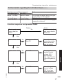
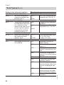
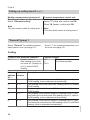
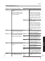
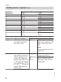
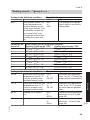
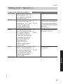
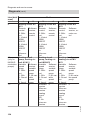
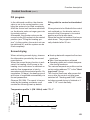
Function sequence and possible faults
Display
No
Control unit issues a heat demand
Action
Increase set value
and ensure heat is
drawn off
Yes
Fan starts
No
After approx. 51 s,
fault F9
Check the fan, fan
connecting cables,
power at the fan
and fan control
No
Fault EE
Check ignition
module (control
voltage 230 V
across plugs
"X2.1" and "X2.2").
Check the gas supply.
No
Fault EE
Check the gas train
(control voltage
230 V) and gas
supply pressure
Ignition
Yes
5772 909 GB
Gas train opens
37
Service
Yes
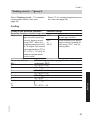
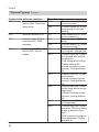
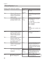
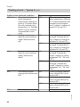
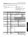
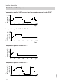
Commissioning, inspection, maintenance
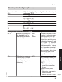
Further details regarding the individual steps (cont.)
Yes
Ionisation current
builds
Symbol A
No
Fault EE
Check the ionisation electrode adjustment and the
gas line for airlocks.
Stops below the
set boiler water
temperature and
restarts immediately
Check the flue system for tightness
(flue gas recirculation); check the gas
flow pressure
Fault E3
Ensure adequate
heat transfer.
Press reset button
R.
Check gap between ionisation
electrode and
burner gauze assembly.
Check allocation of
gas type (coding
address 82, gas
train setting).
Check flue system;
remedy flue gas recirculation if required.
Press reset button
R.
Yes
Burner in operation
No
Automatic calibration of the combustion controller
No
Fault Eb
For further details on faults, see
page 110.
38
5772 909 GB
Yes
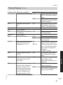
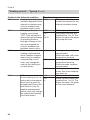
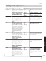
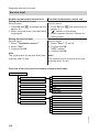
Commissioning, inspection, maintenance
Further details regarding the individual steps (cont.)
Max. heating output setting
The maximum output for heating operation can be limited. The limit is set via
the modulation range. The max. adjustable heating output is limited upwards by
the boiler coding card.
Weather-compensated control unit
Service menu
1. Press OK and å simultaneously for
approx. 4 s.
2. "Service functions"
3. "Max. output"
4. "Change?" Select "Yes".
A value is shown on the display (e.g.
"85"). In the delivered condition, this
value represents 100 % of rated heating output.
5. Set the required value.
Constant temperature control unit
Service menu
1. Press OK and å simultaneously for
approx. 4 s.
2. Select "3" with Ú and confirm with
OK.
A value flashes on the display (e.g.
"85") and "A" appears. In the delivered condition, this value represents
100 % of rated heating output.
3. Select required value and confirm with
OK.
A
5772 909 GB
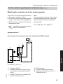
A Combustion air aperture
For balanced flue systems tested
together with the wall mounted gas fired
boiler, the requirement for a tightness
test during commissioning by the flue
gas inspector is not applicable.
We recommend that your heating engineer carries out a simple leak/tightness
test during the commissioning of your
system. For this, it would be sufficient to
check the CO2 or O2 concentration in the
combustion air at the annular gap of the
balanced flue pipe.
The flue pipe is deemed to be gas-tight
if the CO2 concentration in the combustion air is no higher than 0.2 % or the
O2 concentration is at least 20.6 %.
If actual CO2 values are higher or O2 values are lower, then pressure test the flue
pipe with a static pressure of 200 Pa.
39
Service
Tightness test for balanced flue system (annular gap check)
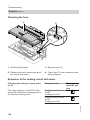
Commissioning, inspection, maintenance
Further details regarding the individual steps (cont.)
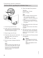
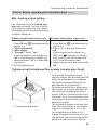
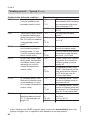
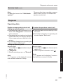
Burner removal
G
4x
E
F
D
C
B
A
1. Switch OFF the power supply and the
ON/OFF switch at the control unit.
2. Close the gas shut-off valve and safeguard against reopening.
5. Undo four screws G and remove the
burner.
!
Please note
Prevent damage to the
burner.
Never rest the burner on the
burner gauze assembly.
5772 909 GB
3. Remove cables from fan motor A,
gas train B, ignition and ionisation
electrode C, ignition unit D and
earth tab E.
4. Undo gas supply pipe fitting F.
40
Commissioning, inspection, maintenance
Further details regarding the individual steps (cont.)
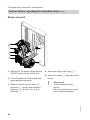
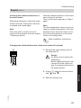
Checking the burner gasket and burner gauze assembly
Check burner gasket A and burner
gauze assembly E for possible damage
and replace if required.
B
F
E
D A
2x
2x
Service
C
5772 909 GB
1. Remove electrodes B.
2. Undo two retaining clips C on thermal insulation ring D and then
remove thermal insulation ring D.
3. Undo two Torx screws and remove
burner gauze assembly E with gasket F.
41
Commissioning, inspection, maintenance
Further details regarding the individual steps (cont.)
6. Fit electrodes B.
4. Insert new burner gauze assembly
E with new gasket F and secure.
!
!
Please note
Fasten screws tightly enough
Please note
Fasten screws tightly enough
to ensure the components are
not being damaged and are
functioning correctly.
to ensure the components are
not being damaged and are
functioning correctly.
5. Fit thermal insulation ring D.
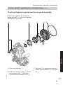
Checking and adjusting the ignition and ionisation electrodes
5 +30
6 +20
10 ±1
B
A Ignition electrodes
B Ionisation electrode
1. Check the electrodes for wear and
contamination.
3. Check the electrode gaps. If the gaps
are not as specified or the electrodes
are damaged, replace the electrodes
together with new gaskets and adjust
them as required. Tighten electrode
fixing screws.
2. Clean the electrodes with a small
brush (not with a wire brush) or sandpaper.
!
Please note
Fasten screws tightly enough
to ensure the components are
not being damaged and are
functioning correctly.
42
5772 909 GB
A
4 +0.5
0
A
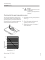
Commissioning, inspection, maintenance
Further details regarding the individual steps (cont.)
Cleaning the heating surfaces
!
Please note
There should be no scratches or
other damage on the heat
exchanger surface that comes
into contact with hot gases. This
could lead to corrosion damage.
Note
Discolouration of the heat exchanger
surface is a normal sign of usage. It has
no impact on the function and service life
of the heat exchanger.
The use of chemical cleaning agents is
not necessary.
Never use brushes to clean the
heating surfaces.
Brushing can cause existing
deposits to get stuck in the coil
gaps.
A
1. Use a vacuum cleaner to remove
deposits from heating surfaces A of
the heat exchanger.
2. If required, rinse heating surfaces
A with water.
3. Check condensate drain and clean
siphon. See the following chapter.
Service
Checking the condensate drain and cleaning the siphon
5772 909 GB
Multi boiler system:
Clean the siphon in the flue gas header
as well.
43
Commissioning, inspection, maintenance
Further details regarding the individual steps (cont.)
A
B
1. Check at the siphon that the condensate can drain freely.
2. Remove retaining clip A and siphon
B.
Note
Never twist the supply hose during
assembly. Route the drain hose without any bends and with a constant
fall.
5772 909 GB
3. Clean siphon B.
4. Fill siphon B with water and fit in
place. Put on retaining clip A.
44
Commissioning, inspection, maintenance
Further details regarding the individual steps (cont.)
Fitting the burner
G
4x
E
F
D
C
B
A
!
Please note
Fasten screws tightly enough
to ensure the components are
not being damaged and are
functioning correctly.
Danger
Escaping gas leads to a risk of
explosion.
Check all fittings for gas tightness.
4. Connect cables from fan motor A,
gas train B, ionisation electrode
C, ignition unit D and earth tab
E.
5772 909 GB
2. Fit gas supply pipe F with a new
gasket.
3. Check the gas connections for tightness.
45
Service
1. Fit the burner and tighten screws G
diagonally.
Commissioning, inspection, maintenance
Further details regarding the individual steps (cont.)
Checking the flow limiter (only for combi boilers)
1. Switch OFF the control unit, shut off
the cold water line and drain the DHW
side of the boiler.
2. Undo Allen screws A.
Note
Residual water may escape during
dismantling.
3. Remove flow switch B and take out
flow limiter C downwards.
C
4. Check flow limiter C; replace if
scaled or damaged, then re-insert.
Refit flow switch B.
B
A
Checking the expansion vessel and system pressure
Check whether the installed diaphragm
expansion vessel is adequate for the
system water pressure (only g).
Carry out this test on a cold system.
46
1. Drain the system or close the cap
valve on the expansion vessel and
reduce the pressure until the pressure gauge indicates "0".
2. If the pre-charge pressure in the
expansion vessel is lower than the
static system pressure, top up with
sufficient nitrogen to raise the precharge pressure 0.1 to 0.2 bar higher
than the static system pressure.
5772 909 GB
Note
The diaphragm expansion vessel can
lose some charge pressure over a time
in use. When the boiler heats up, the
pressure gauge will indicate a higher
pressure of 2 or 3 bar. The safety valve
too can respond and discharge excess
volume (only g).
Commissioning, inspection, maintenance
Further details regarding the individual steps (cont.)
3. Top up with water until the charge
pressure of the cooled system is at
least 1.0 bar, and is 0.1 to 0.2 bar
higher than the pre-charge pressure
of the expansion vessel.
Permiss. operating pressure: 3 bar
Checking all gas equipment for tightness at operating pressure
Danger
Escaping gas leads to a risk of
explosion.
Check all gas equipment for tightness.
Note
Only use suitable and approved leak
detection agents (EN 14291) and devices for the tightness test. Leak detection
agents with unsuitable constituents
(e.g. nitrites, sulphides) can cause material damage.
Remove residues of the leak detection
agent after testing.
Checking the combustion quality
Note
Operate the appliance with uncontaminated combustion air to prevent operating faults and damage.
5772 909 GB
CO content
■ The CO content must be < 400 ppm for
all gas types.
CO2 or O2 content
■ The CO2 content must be within the
following limits (for upper and lower
heating output respectively):
– 7.5 to 9.5 % for natural gas E and LL
– 8.8 to 11.1 % for LPG P
■ For all gas types, the O2 content must
be between 4.0 and 7.6 %.
If the actual CO, CO2 or O2 values lie
outside their respective ranges, proceed
with the following steps:
■ Carry out a tightness test of the balanced flue system, see page 39.
■ Check the ionisation electrode and
connecting cable, see page 42.
Note
During commissioning, the combustion
controller carries out an automatic calibration. Only test the emissions approx.
30 s after the burner has started.
47
Service
The electronic combustion controller
automatically ensures optimum combustion quality. During commissioning/
maintenance, only the combustion values need to be checked. As part of this,
measure the CO content and CO2 or O2
content and enter into the report on
page 179. For a description of the electronic combustion controller functions,
see page 156.
Commissioning, inspection, maintenance
Further details regarding the individual steps (cont.)
A
4. Check the CO2 content. Should the
actual value deviate from the aforementioned ranges by more than 1 %,
implement steps from page 47.
5. Enter actual values into the report.
6. Set the upper heating output (see
page 48).
1. Connect a flue gas analyser at flue
gas port A on the boiler flue connection.
2. Open the gas shut-off valve, start the
boiler and create a heat demand.
7. Check the CO2 content. Should the
actual value deviate from the aforementioned ranges by more than 1 %,
implement steps from page 47.
8. After testing, press OK.
9. Enter actual values into the report.
3. Set the lower heating output (see
page 48).
Weather-compensated control unit
Service menu
1. Press OK and å simultaneously for
approx. 4 s.
2. "Actuator test"
3. Select the lower heating output:
Select "Base load OFF". Then "Base
load ON" appears and the burner operates at its lower heating output.
4. Select the upper heating output:
Select "Full load OFF". Then "Full
load ON" appears and the burner operates at its upper heating output.
5. Ending output selection:
Press ä.
48
Constant temperature control unit
Service menu
1. Press OK and å simultaneously for
approx. 4 s.
2. Select " " with Ú and confirm with
OK.
The display shows "I" and "ON" flashes.
3. Select the lower heating output:
Press OK, "ON" will be displayed constantly.
4. Select the upper heating output:
Press ä.
5. Select "2" with Ú; "ON" flashes.
6. Press OK, "ON" will be displayed constantly.
7. Ending output selection:
Press ä.
5772 909 GB
Select higher/lower heating output
Commissioning, inspection, maintenance
Further details regarding the individual steps (cont.)
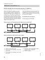
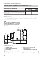
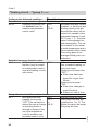
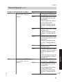
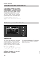
Matching the control unit to the heating system
The control unit must be adjusted subject
to the system equipment level.
■ To do this, select the relevant system
scheme (see the following diagrams).
■ Set the codes in conjunction with the
accessories fitted:
Note
Various system components are recognised automatically by the control unit
and the relevant codes are adjusted
automatically.
For coding steps, see page 60.
Installation and service instructions for accessories
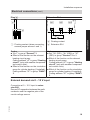
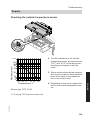
System version 1
One heating circuit without mixer A1 (with/without DHW heating)
3
6
2
1
4
Service
5
5772 909 GB
ID: 4605145_1001_01
1 Vitodens 200-W
2 Outside temperature sensor (only
for weather-compensated control
units)
3 Vitotrol 100 (only for constant temperature control units)
4 DHW cylinder
5 Cylinder temperature sensor
6 Heating circuit without mixer A1
(heating circuit 1)
49
Commissioning, inspection, maintenance
Further details regarding the individual steps (cont.)
Function/system components
Operation with LPG
System with DHW circulation pump:
DHW circulation pump connection at internal extension H1 or H2
Code
Adjust
Group
82:1
"General"/1
—
—
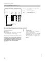
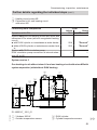
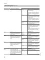
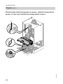
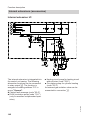
System version 2
One heating circuit without mixer A1 and one heating circuit with mixer M2
(with/without DHW heating)
Note
The flow rate of the heating circuit without mixer must be at least 30 % greater
than the flow rate of the heating circuit
with mixer.
5
2
6
7
8
1
3
4
9
qP M
1
2
3
4
5
50
Vitodens 200-W
Outside temperature sensor
DHW cylinder
Cylinder temperature sensor
Heating circuit without mixer A1
(heating circuit 1)
6 Heating circuit with mixer M2
(heating circuit 2)
7 Temperature limiter to restrict the
maximum temperature of underfloor
heating systems
8 Flow temperature sensor M2
5772 909 GB
ID: 4605148_1001_01
Commissioning, inspection, maintenance
Further details regarding the individual steps (cont.)
9 Heating circuit pump M2
qP Extension kit for one heating circuit
with mixer M2
Function/system components
Operation with LPG
System only with one heating circuit with mixer with
extension kit for mixer (without unregulated heating
circuit)
■ with DHW cylinder or instantaneous water heater
■ without DHW cylinder or instantaneous water heater
System with DHW circulation pump:
DHW circulation pump connection at internal extension H1 or H2
Code
Adjust
Group
82:1
"General"
00:4
00:3
"General"
"General"
—
—
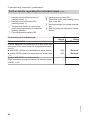
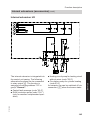
System version 3
One heating circuit without mixer A1 and one heating circuit with mixer M2 with
system separation (with/without DHW heating)
6
5
7
8
1
3
4
qW
9
qP M
qQ
Service
2
5772 909 GB
ID: 4605147_1001_01
1 Vitodens 200-W
2 Outside temperature sensor
3 DHW cylinder
4 Cylinder temperature sensor
51
Commissioning, inspection, maintenance
Further details regarding the individual steps (cont.)
5 Heating circuit without mixer A1
(heating circuit 1)
6 Heating circuit with mixer M2
(heating circuit 2)
7 Temperature limiter to restrict the
maximum temperature of underfloor
heating systems
8 Flow temperature sensor M2
9 Heating circuit pump M2
qP Extension kit for one heating circuit
with mixer M2
qQ Heat exchanger for system separation
qW Sub-mounting kit with mixer (accessories)
Function/system components
00:4
00:3
"General"
"General"
—
—
5772 909 GB
Operation with LPG
System only with one heating circuit with mixer with
extension kit for mixer (without unregulated heating
circuit)
■ with DHW cylinder or instantaneous water heater
■ without DHW cylinder or instantaneous water heater
System with DHW circulation pump:
DHW circulation pump connection at internal extension H1 or H2
Code
Adjust
Group
82:1
"General"
52
Commissioning, inspection, maintenance
Further details regarding the individual steps (cont.)
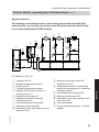
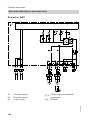
System version 4
One heating circuit without mixer, one heating circuit with mixer M2 (with
extension kit), one heating circuit with mixer M3 (with extension kit) and low
loss header (with/without DHW heating)
5
8
7
qQ
qW
qE
2
1
3
4
6
qU
9
M
qP
qR
M
qT
qZ
1
2
3
4
5
6
7
qQ Heating circuit with mixer M3
(heating circuit 3)
qW Temperature limiter to restrict the
maximum temperature of underfloor
heating systems
qE Flow temperature sensor M3
qR Heating circuit pump M3
qT Extension kit for one heating circuit
with mixer M3
qZ Low loss header
qU Flow temperature sensor, low loss
header
5772 909 GB
8
9
qP
Vitodens 200-W
Outside temperature sensor
DHW cylinder
Cylinder temperature sensor
Heating circuit without mixer A1
(heating circuit 1)
Heating circuit pump A1
Heating circuit with mixer M2
(heating circuit 2)
Flow temperature sensor M2
Heating circuit pump M2
Extension kit for one heating circuit
with mixer M2
53
Service
ID: 4605149_1001_01
Commissioning, inspection, maintenance
Further details regarding the individual steps (cont.)
Function/system components
Operation with LPG
System only with two heating circuits with mixer with
extension kit for mixer (without unregulated heating
circuit)
■ with DHW cylinder or instantaneous water heater
■ without DHW cylinder or instantaneous water heater
System without DHW circulation pump:
Heating circuit pump A1 connection at internal extension H1 or H2
System with DHW circulation pump:
Heating circuit pump A1 connection at extension
AM1, terminal A1
DHW circulation pump connection at extension AM1,
terminal A2
System with low loss header
Code
Adjust
Group
82:1
"General"
00:8
00:7
"General"
"General"
53:2
"General"
—
—
—
—
04:0
"Boiler"
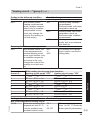
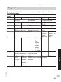
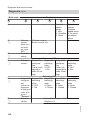
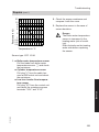
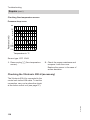
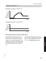
Adjusting the heating curves (only for weather-compensated
control units)
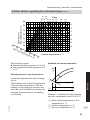
The heating curves illustrate the relationship between the outside temperature
and the boiler water or flow temperature.
To put it simply, the lower the outside
temperature, the higher the boiler water
or flow temperature.
The boiler water or flow temperature in
turn affects the room temperature.
5772 909 GB
Settings in the delivered condition:
■ Slope = 1.4
■ Level = 0
Note
If the heating system includes heating
circuits with mixers, then the flow temperature of the heating circuit without
mixer is higher by a selected differential
(8 K in the delivered condition) than the
flow temperature of the heating circuits
with mixers.
The differential temperature is adjustable via coding address "9F" in the "General" group.
54
Commissioning, inspection, maintenance
35
Boiler water or
Flow temperature in °C
1.6
1.4
80
1.2
70
1.0
60
0.8
50
0.6
40
30
3
Se 0 2
t ro
5
om
10 5
tem 20
per 15
atu
1
re
in ° 0 5
C
1.8
2.0
2.8
Slope
2.6
2.4
2.2
3.0
90
3.4
3.2
Further details regarding the individual steps (cont.)
0.4
0.2
0 -5 -10 -15 -20 -25 -30
Outside temperature in °C
Slope setting ranges:
■ Underfloor heating systems: 0.2 to 0.8
■ Low temperature heating systems: 0.8
to 1.6
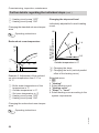
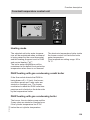
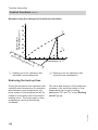
Standard set room temperature
90
A
Selecting the set room temperature
5772 909 GB
C 26
D
+2
0
B -20
Service
Individually adjustable for each heating
circuit.
The heating curve is offset along the axis
of the set room temperature. With the
heating circuit pump logic function enabled, the curve modifies the starting and
stopping characteristics of the heating
circuit pump.
E
Example 1: Adjustment of the standard
set room temperature from 20 to 26 °C
A Boiler water temperature or flow
temperature in °C
B Outside temperature in °C
C Set room temperature in °C
55
Commissioning, inspection, maintenance
Further details regarding the individual steps (cont.)
D Heating circuit pump "OFF"
E Heating circuit pump "ON"
Changing the standard set room temperature
Changing the slope and level
Individually adjustable for each heating
circuit.
90
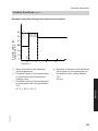
Reduced set room temperature
90
A
C
D
+2
0
14
5
B -20
E
Example 2: Adjustment of the reduced
set room temperature from 5 °C to
14 °C
A Boiler water temperature or flow
temperature in °C
B Outside temperature in °C
C Set room temperature in °C
D Heating circuit pump "OFF"
E Heating circuit pump "ON"
Boiler water or
flow temperature in °C
Operating instructions
3.5
1.4
A
B
0.2
+20
-20
Outside temperature in °C
A Changing the slope
B Changing the level (vertical parallel
offset of the heating curve)
Extended menu:
1. å
2. "Heating"
3. Select heating circuit.
4. "Heating curve"
5. "Slope" or "Level"
6. Select heating curve according to the
system requirements.
Changing the reduced set room temperature
5772 909 GB
Operating instructions
56
Commissioning, inspection, maintenance
Further details regarding the individual steps (cont.)
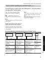
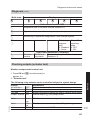
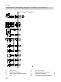
Connecting the control unit to the LON system - only for weathercompensated control units
The LON communication module
(accessories) must be plugged in.
Installation instructions
LON communication module
Note
In the same LON system, the same subscriber number must not be allocated
twice.
Only one Vitotronic may be programmed as fault manager.
Note
The data transfer via LON can take several minutes.
Single boiler system with Vitotronic
200-H and Vitocom 200 (example)
Set the LON subscriber numbers and
further functions via code 2 (see the following table).
All coding addresses in the table are listed in the "General" group.
Boiler control unit
Vitotronic 200-H
Vitotronic 200-H
Vitocom
Subscriber no. 10,
Code "77:10".
Control unit is not
fault manager,
Code "79:0".
Control unit receives
the time,
Set code "81:3".
Control unit receives
outside temperature,
Set code "97:1".
LON
Subscriber no. 11,
Set code "77:11".
Control unit is not
fault manager,
Code "79:0".
Control unit receives
the time,
Set code "81:3".
Control unit receives
outside temperature,
Set code "97:1".
Subscriber
no. 99.
Device is fault
manager.
Device receives the
time.
—
5772 909 GB
Subscriber no. 1,
Code "77:1".
Control unit is fault
manager,
Code "79:1".
Control unit transmits
the time,
Code "7b:1".
Control unit transmits
outside temperature,
Set code "97:2".
LON
57
Service
LON
Commissioning, inspection, maintenance
Further details regarding the individual steps (cont.)
Boiler control unit
Viessmann system
number,
Code "98:1".
LON subscriber fault
monitoring,
Code "9C:20".
Vitotronic 200-H
Viessmann system
number,
Code "98:1".
LON subscriber fault
monitoring,
Code "9C:20".
Carrying out a LON subscriber check
The subscriber check is used to test
communication with the system devices
connected to the fault manager.
Preconditions:
■ The control unit must be programmed
as fault manager (code "79:1" in the
"General" group).
■ The LON subscriber number must be
programmed in all control units.
■ The LON subscriber list in the fault
manager must be up to date.
4. Select subscriber (e.g. subscriber 10).
5. Start the subscriber check with "OK".
■ Successfully tested subscribers are
designated with "OK".
■ Unsuccessfully tested subscribers are
designated with "Not OK".
Note
To carry out a new subscriber check,
create a new subscriber list with
"Delete list?" (subscriber list is updated).
Note
During the subscriber check, the display
for the relevant subscriber shows the
subscriber no. and "Wink" for approx.
1 min.
5772 909 GB
Service menu:
1. Press OK and
simultaneously for
approx. 4 s.
2. "Service functions"
3. "Subscriber check"
Vitotronic 200-H
Vitocom
Viessmann system
—
number,
Code "98:1".
LON subscriber fault —
monitoring,
Code "9C:20".
58
Commissioning, inspection, maintenance
Further details regarding the individual steps (cont.)
Calling up and resetting the service display
The red fault indicator flashes when the
limits set in coding addresses "21" and
"23" have been reached. (Coding
address in group "Boiler" (weathercompensated control unit) or group 2
(constant temperature control unit).)
Weather-compensated control unit
Display
"Service" and "¸"
Constant temperature control unit
The specified hours run or the specified
interval with calendar symbol "ý" (subject to setting) and "¸"
Acknowledging a service
Press OK.
Service the appliance.
Press OK.
Service the appliance.
Note
An acknowledged service message that
was not reset appears again the following
Monday.
Note
An acknowledged service message that
was not reset appears again after
7 days.
Service
After the service has been carried out: Reset the codes
Service menu:
Reset code "24:1" in group 2 to "24:0".
1. Press OK and å simultaneously for
Note
approx. 4 s.
The selected service parameters for
2. "Service functions"
hours run and interval restart at "0".
3. "Service reset"
Note
The selected service parameters for
hours run and interval restart at "0".
5772 909 GB
Instructing the system user
The system installer should hand the
operating instructions to the system user
and instruct the user in operating the
system.
This includes all components installed as
accessories, e.g. remote control units. In
addition, the system installer must make
the user aware of the required maintenance work.
59
Code 1
Calling up coding level 1
Calling up coding level 1
■ On weather-compensated control
units, codes are displayed as plain
text.
■ Codes that have not been assigned
due to the heating system equipment
level or the setting of other codes are
not displayed.
■ Heating systems with one heating circuit without mixer and one or two heating circuits with mixer:
Constant temperature control unit
1:
2:
3:
4:
5:
6:
"General"
"Boiler"
"DHW"
"Solar"
"Heating circuit 1"
"All codes std device"
In this group, all coding addresses are
displayed in ascending order.
7: "Standard setting"
Service menu:
1. Press OK and å simultaneously for
approx. 4 s.
2. Select "1" with Ú for coding level 1
and confirm with OK.
3. "I" flashes on the display for the coding
addresses in group 1.
4. Select the group of required coding address with V/v and confirm with OK.
5. Select coding address with V/v.
6. Set value according to the following tables with V/v and confirm with OK.
5772 909 GB
Weather-compensated control unit
The codes are divided into groups
■ "General"
■ "Boiler"
■ "DHW"
■ "Solar"
■ "Heating circuit 1/2/3"
■ "All codes std device"
In this group, all coding addresses from
coding level 1 (except the coding addresses from the "Solar" group) are
displayed in ascending order.
■ "Standard setting"
Call up code 1
Service menu:
1. Press OK and å simultaneously for
approx. 4 s.
2. "Coding level 1"
3. Select group of required coding address.
4. Select coding address.
5. Select value according to the following
tables and confirm with OK.
The heating circuit without mixer is
designated "Heating circuit 1" and
the heating circuits with mixer as
"Heating circuit 2" or "Heating circuit 3".
If the heating circuits were given individual designations, the selected designation and "HC1", "HC2" or "HC3"
appear instead.
60
Code 1
Calling up coding level 1 (cont.)
Weather-compensated control unit
Constant temperature control unit
Resetting all codes to their delivered condition
Select "Standard setting".
Select "7" with Ú and confirm with OK.
When " " flashes, confirm with OK.
Note
This also resets the codes at coding lev- Note
el 2.
This also resets the codes at coding level 2.
"General"/group 1
Select "General" for weather-compensated control units (see page 60).
Select "1" for constant temperature control units (see page 60).
Coding
Coding in the delivered condition
System design
00:1
System version 1:
One heating circuit without mixer A1 (heating circuit 1), without DHW
heating
5772 909 GB
3
2, 3
4
2, 3
5
2, 3
6
2, 3
00:2
to
00:10
For system schemes, see
the following table:
Description
One heating circuit without mixer A1 (heating circuit 1), with
DHW heating (code is adjusted automatically)
One heating circuit with mixer M2 (heating circuit 2), without
DHW heating
One heating circuit with mixer M2 (heating circuit 2), with
DHW heating
One heating circuit without mixer A1 (heating circuit 1) and
one heating circuit with mixer M2 (heating circuit 2), without
DHW heating (code is adjusted automatically)
One heating circuit without mixer A1 (heating circuit 1) and
one heating circuit with mixer M2 (heating circuit 2), with DHW
heating (code is adjusted automatically)
61
Service
Value
System
address version
00: ...
2
1
Possible change
Code 1
"General"/group 1 (cont.)
Value
System
address version
00: ...
7
4
8
4
9
4
10
4
Description
One heating circuit with mixer M2 (heating circuit 2) and one
heating circuit with mixer M3 (heating circuit 3), without DHW
heating
One heating circuit with mixer M2 (heating circuit 2) and one
heating circuit with mixer M3 (heating circuit 3), with DHW
heating
One heating circuit without mixer A1 (heating circuit 1), one
heating circuit with mixer M2 (heating circuit 2) and one heating circuit with mixer M3 (heating circuit 3), without DHW
heating (code is adjusted automatically)
One heating circuit without mixer A1 (heating circuit 1), one
heating circuit with mixer M2 (heating circuit 2) and one heating circuit with mixer M3 (heating circuit 3), with DHW heating
(code is adjusted automatically)
5772 909 GB
Coding in the delivered condition
Possible change
Boiler/burner
51:0
System with low loss
51:1
System with low loss headheader:
er:
Internal circulation pump
When there is a heat dealways starts when there
mand, the internal circulais a heat demand
tion pump is only started if
the burner is operational.
Circulation pump is switched off on expiry of run-on
time.
51:2
System with heating water
buffer cylinder:
When there is a heat demand, the internal circulation pump is only started if
the burner is operational.
Circulation pump is switched off on expiry of run-on
time.
62
Code 1
"General"/group 1 (cont.)
Coding in the delivered condition
Subscriber no.
77:1
LON subscriber number
(only for weather-compensated control units)
Possible change
77:2
to
77:99
LON subscriber number,
adjustable from 1 to 99:
1 - 4 = Boiler
5 = Cascade
10 - 97 = Vitotronic 200-H
98 = Vitogate
99 = Vitocom
Note
Allocate each number only
once.
Lock out controls
8F:0
Operation in the standard 8F:1
menu and extended
menu enabled.
Note
The respective code is
only activated when you
exit the service menu.
8F:2
Operation in standard
menu and extended menu
blocked.
Emissions test mode can
be enabled.
Operation enabled in the
standard menu and
blocked in the extended
menu.
Emissions test mode can
be enabled.
Set flow temperature for
external demand adjustable from 0 to 127 °C (limited
by boiler-specific parameters)
5772 909 GB
Set flow temperature for external demand
9b:70
Set flow temperature for 9b:0
external demand 70 °C
to
9b:127
Apartment building
Separate adjustment of
holiday program and time
program for DHW heating
possible
63
Service
Detached house/apartment building
7F:1
Detached house (only for 7F:0
weather-compensated
control units)
Code 1
"Boiler"/group 2
Select "Boiler" for weather-compensated control units (see page 60).
Select "2" for constant temperature control units (see page 60).
Coding
Coding in the delivered condition
Possible change
Single/multi boiler system
01:1
Do not adjust (only for
constant temperature
control units)
Burner service in 100 hours
21:0
No service interval (hours 21:1
The number of hours run
run) selected
to
before the burner should
21:100
be serviced is adjustable
from 100 to 10 000 h
One step ≙ 100 h
Service interval in months
23:0
No interval for burner
23:1
Interval adjustable from 1
service
to
to 24 months
23:24
Service status
24:0
"Service" not shown on 24:1
"Service" is shown on disdisplay
play (the address is automatically set and must be
manually reset after a service has been carried out)
Filling/Venting
2F:0
Venting program/fill pro- 2F:1
Venting program enabled
gram disabled
2F:2
Fill program enabled
"DHW"/group 3
Select "3" for constant temperature control units (see page 60).
5772 909 GB
Select "DHW" for weather-compensated control units (see page 60).
64
Code 1
"DHW"/group 3 (cont.)
Coding
Coding in the delivered condition
Possible change
Set DHW temperature reheating suppression
67:40
For solar DHW heating:
67:0
Set DHW temperature adSet DHW temperature
to
justable from 0 to 95 °C
40 °C. Reheating is sup- 67:95
(limited by boiler-specific
pressed above the selecparameters)
ted set temperature (boiler is only connected as
backup if the rise in cylinder temperature is too
low).
Cannot be adjusted on
combi boilers.
Enable DHW circulation pump
73:0
DHW circulation pump:
73:1
"ON" from once per hour
"ON" according to time
to
for 5 min up to
program (only for weath- 73:6
6 times per hour for 5 min
er-compensated control
during the time program
units and system boilers) 73:7
Constantly "ON"
"Solar"/group 4
Note
The solar group is only displayed if a
solar control module, type SM1, is connected.
Service
Select "Solar" for weather-compensated control units (see page 60).
Select "4" for constant temperature control units (see page 60).
Coding
Coding in the delivered condition
Speed control solar circuit pump
02:0
Solar circuit pump is not
speed-controlled.
Possible change
02:1
5772 909 GB
02:2
Solar circuit pump is
speed-controlled with
wave packet control.
Solar circuit pump is
speed-controlled with
PWM control.
65
Code 1
"Solar"/group 4 (cont.)
Possible change
08:10
to
08:90
Set DHW temperature adjustable from 10 to 90 °C.
0A:0
Stagnation time reduction
disabled.
Temperature differential
adjustable from 1 to 40 K.
0A:1
to
0A:40
0F:1
to
0F:255
Flow rate adjustable from
0.1 to 25.5 l/min;
1 step ≙ 0.1 l/min.
20:1
Additional function for
DHW heating.
Differential temperature
control 2.
Differential temperature
control 2 and auxiliary function.
Differential temperature
control 2 for central heating
backup.
Thermostat function.
Thermostat function and
auxiliary function.
Solar heating via external
heat exchanger without additional temperature sensor.
Solar heating via external
heat exchanger with additional temperature sensor.
Solar heating of two DHW
cylinders.
20:2
20:3
20:4
20:5
20:6
20:7
20:8
20:9
66
5772 909 GB
Coding in the delivered condition
Cylinder maximum temperature
08:60
Set DHW temperature
(maximum cylinder temperature) 60 °C.
Stagnation time reduction
0A:5
Temperature differential
for stagnation time reduction (reduction in the
speed of the solar circuit
pump to protect system
components and heat
transfer medium) 5 K.
Flow rate solar circuit
0F:70
Solar circuit flow rate at
the maximum pump
speed 7 l/min.
Extended solar control functions
20:0
No extended control function enabled.
Code 1
"Heating circuit ..."/group 5
Select "Heating circuit ..." for weathercompensated control units (see
page 60).
Select "5" for constant temperature control units (see page 60).
Coding
Coding in the delivered condition
Possible change
Economy function outside temperature
A5:5
With heating circuit pump A5:0
Without heating circuit
logic function (economy
pump logic function
control): heating circuit
A5:1
With heating circuit pump
pump "OFF" when the
to
logic function: Heating ciroutside temperature (AT) A5:15
cuit pump "OFF"; see folis 1 K higher than the set
lowing table
room temperature (RTset)
AT > RTset + 1 K (only for
weather-compensated
control units)
Service
With heating circuit pump logic function: Heating circuit pump "OFF"
AT > RTset + 5 K
AT > RTset + 4 K
AT > RTset + 3 K
AT > RTset + 2 K
AT > RTset + 1 K
AT > RTset
AT > RTset – 1 K
AT > RTset – 9 K
5772 909 GB
Parameter address
A5:...
1
2
3
4
5
6
7
to
15
67
Code 1
Coding in the delivered condition
Possible change
Extended economy function adjusted outside temperature
A6:36
Extended economy con- A6:5
Extended economy control
trol disabled (only for
to
enabled, i.e. the burner and
weather-compensated
A6:35
heating circuit pump will
control units)
stop and the mixer will be
closed at a variable value,
adjustable between 5 and
35 °C plus 1 °C. The base
value is the adjusted outside temperature. This value is based on the actual
outside temperature and a
time constant, which takes
the cooling down of an
average building into consideration.
Extended economy function mixer
A7:0
Without mixer economy
A7:1
With mixer economy funcfunction (only for weathtion (extended heating cirer-compensated control
cuit pump logic):
units and heating circuits
Heating circuit pump also
with mixer)
"OFF":
■ If the mixer has been
closed for longer than
20 min.
Heating circuit pump
"ON":
■ If the mixer changes to
control function
■ If there is a risk of frost
Pump idle time, transition reduced mode
A9:7
With pump idle time:
A9:0
Without pump idle time
Heating circuit pump
A9:1
With pump idle time, ad"OFF" if the set value is
to
justable from 1 to 15. The
altered through a change A9:15
higher the value, the longer
in operating mode or
the pump idle time.
through a change in the
set room temperature
(only for weather-compensated control units)
68
5772 909 GB
"Heating circuit ..."/group 5 (cont.)
Code 1
"Heating circuit ..."/group 5 (cont.)
Coding in the delivered condition
Possible change
Weather-compensated/room temperature hook-up
b0:0
With remote control:
b0:1
Heating mode: weatherHeating mode/reduced
compensated
mode: weather-compenReduced mode: with room
sated (only for weathertemperature hook-up
compensated control
b0:2
Heating mode: with room
units; only change the
temperature hook-up
code for the heating cirReduced mode: weathercuit with mixer)
compensated
b0:3
Heating mode/reduced
mode: with room temperature hook-up
Economy function room temperature
b5:0
With remote control: No b5:1
For heating circuit pump
room temperature-deto
logic function, see the folpendent heating circuit
b5:8
lowing table:
pump logic function (only
for weather-compensated control units; only
change the code for the
heating circuit with mixer)
5772 909 GB
With heating circuit pump logic function:
Heating circuit pump "OFF"
Heating circuit pump "ON"
RTactual > RTset + 5 K
RTactual < RTset + 4 K
RTactual > RTset + 4 K
RTactual < RTset + 3 K
RTactual > RTset + 3 K
RTactual < RTset + 2 K
RTactual > RTset + 2 K
RTactual < RTset + 1 K
RTactual > RTset + 1 K
RTactual < RTset
RTactual > RTset
RTactual < RTset – 1 K
RTactual > RTset – 1 K
RTactual < RTset – 2 K
RTactual > RTset – 2 K
RTactual < RTset – 3 K
Coding in the delivered condition
Min. flow temperature heating circuit
C5:20
Electronic minimum flow
temperature limit 20 °C
(only for weather-compensated control units)
Service
Parameter address b5:...
1
2
3
4
5
6
7
8
Possible change
C5:1
to
C5:127
Minimum limit adjustable
from 1 to 127 °C (limited by
boiler-specific parameters)
69
Code 1
"Heating circuit ..."/group 5 (cont.)
5772 909 GB
Coding in the delivered condition
Possible change
Max. flow temperature heating circuit
C6:74
Electronic maximum flow C6:10
Maximum limit adjustable
temperature limit 74 °C
to
from 10 to 127 °C (limited
(only for weather-comC6:127
by boiler-specific paramepensated control units)
ters)
Heating program - changeover
d5:0
The external heating pro- d5:1
The external heating program changeover
gram changeover switches
switches the heating proto "Constant operation with
gram to "Constant operastandard room temperation with reduced room
ture" (subject to coding adtemperature" or "Standby
dress 3A, 3b and 3C)
mode" (only for weathercompensated control
units)
Ext. heating program changeover to heating circuit
d8:0
No heating program
d8:1
Heating program changechangeover via extension
over via input DE1 at exEA1
tension EA1
d8:2
Heating program changeover via input DE2 at extension EA1
d8:3
Heating program changeover via input DE3 at extension EA1
Max. pump speed in standard mode
E6:...
Maximum speed of the
E6:0
Maximum speed adjustavariable speed heating
to
ble from 0 to 100 %
circuit pump in % of the
E6:100
max. speed in standard
mode. Value is specified
by boiler-specific parameters (only for weathercompensated control
units).
70
Code 1
"Heating circuit ..."/group 5 (cont.)
Possible change
E7:0
to
E7:100
Minimum speed adjustable
from 0 to 100 % of the maximum speed
F1:1
to
F1:6
Screed drying adjustable in
accordance with 6 selectable temperature/time profiles (see page 151)
Constant flow temperature
20 °C
F1:15
Party mode time limit
F2:8
Time limit for party mode
or external heating program changeover via button: 8 h (only for weathercompensated control
units)*1
Pump control in "Only DHW"
F6:25
In the "Only DHW" operating mode, the internal
circulation pump is permanently on (only for
constant temperature
control units)
5772 909 GB
Pump control in "Standby mode"
F7:25
In "Standby mode", the
internal circulation pump
is permanently on (only
for constant temperature
control units)
*1
F2:0
F2:1
to
F2:12
F6:0
F6:1
to
F6:24
F7:0
F7:1
to
F7:24
No time limit for party
mode*1
Time limit adjustable from 1
to 12 h*1
In the "Only DHW" operating mode, the internal circulation pump is permanently off
In operating mode "DHW
only", the internal circulation pump will be started 1
to 24 times per day for
10 min each time.
In "Standby mode", the internal circulation pump is
permanently off
In "Standby mode", the internal circulation pump will
be started 1 to 24 times per
day for 10 min each time.
In the "Heating and DHW" program, party mode ends automatically when the
system changes over to operation with standard room temperature.
71
Service
Coding in the delivered condition
Min. pump speed
E7:30
Minimum speed of the
variable speed heating
circuit pump: 30 % of the
max. speed (only for
weather-compensated
control units)
Screed drying
F1:0
Screed drying disabled
(only for weather-compensated control units).
Code 1
"Heating circuit ..."/group 5 (cont.)
5772 909 GB
Coding in the delivered condition
Possible change
Start temperature raising
F8:–5
Temperature limit for ter- F8:+10
Temperature limit adjustaminating reduced mode
to
ble from
–5 °C, see example on
F8:–60
+10 to –60 °C
page 153.
F8:–61
Function disabled
Observe the setting of
coding address "A3". (only for weather-compensated control units)
End temperature raising
F9:–14
Temperature limit for rais- F9:+10
Temperature limit for raising the set reduced room to
ing the set room temperatemperature –14 °C, see F9:–60
ture to the value selected
example on page 153.
for standard mode adjusta(only for weather-comble from
pensated control units)
+10 to –60 °C
Set flow temperature increase
FA:20
Raising the set boiler wa- FA:0
Temperature rise adjustater or flow temperature by to
ble from 0 to 50 %
20 % when changing
FA:50
from operation with reduced room temperature
to operation with standard room temperature.
See example on
page 154 (only for
weather-compensated
control units).
Duration set flow temperature increase
Fb:60
Duration of the set boiler Fb:0
Duration adjustable from 0
water or flow temperature to
to 300 min.
rise (see coding address Fb:300
"FA") 60 min. See example on page 154 (only for
weather-compensated
control units).
72
Code 2
Calling up coding level 2
Calling up coding level 2
■ All codes are accessible in coding
level 2.
■ Codes that have not been assigned
due to the heating system equipment
level or the setting of other codes are
not displayed.
■ The heating circuit without mixer is
designated "Heating circuit 1" and
the heating circuits with mixer as
"Heating circuit 2" or "Heating circuit 3".
5772 909 GB
Constant temperature control unit
1:
2:
3:
4:
5:
6:
"General"
"Boiler"
"DHW"
"Solar"
"Heating circuit 1"
"All codes std device"
In this group, all coding addresses are
displayed in ascending order.
7: "Standard setting"
Service menu:
1. Press OK and å simultaneously for
approx. 4 s.
2. Press OK and ä simultaneously for
approx. 4 s.
3. Select "2" with Ú for coding level 2
and confirm with OK.
4. "I" flashes on the display for the coding
addresses in group 1.
5. Select the group of required coding address with V/v and confirm with OK.
6. Select coding address with V/v.
7. Set value according to the following tables with V/v and confirm with OK.
73
Service
Weather-compensated control unit
The codes are divided into groups
■ "General"
■ "Boiler"
■ "DHW"
■ "Solar"
■ "Heating circuit 1/2/3"
■ "All codes std device"
In this group, all coding addresses (except the coding addresses from the
"Solar" group) are displayed in ascending order.
■ "Standard setting"
Call up code 2
Service menu:
1. Press OK and
simultaneously for
approx. 4 s.
2. Press OK and
simultaneously for
approx. 4 s.
3. "Coding level 2"
4. Select group of required coding address.
5. Select coding address.
6. Select value according to the following
tables and confirm with OK.
If the heating circuits were given individual designations, the selected designation and "HC1", "HC2" or "HC3"
appear instead.
Code 2
Calling up coding level 2 (cont.)
Weather-compensated control unit
Constant temperature control unit
Resetting all codes to their delivered condition
Select "Standard setting".
Select "7" with Ú and confirm with OK.
When " " flashes, confirm with OK.
Note
This also resets codes at coding level 1. Note
This also resets codes at coding level 1.
"General"/group 1
Select "General" for weather-compensated control units (see page 73).
Select "1" for constant temperature control units (see page 73).
Coding
Coding in the delivered condition
00:1
System version 1:
One heating circuit without mixer A1 (heating circuit 1), without DHW
heating
Value
System
address version
00: ...
2
1
2, 3
4
2, 3
5
2, 3
6
2, 3
Description
One heating circuit without mixer A1 (heating circuit 1), with
DHW heating (code is adjusted automatically)
One heating circuit with mixer M2 (heating circuit 2), without
DHW heating
One heating circuit with mixer M2 (heating circuit 2), with
DHW heating
One heating circuit without mixer A1 (heating circuit 1) and
one heating circuit with mixer M2 (heating circuit 2), without
DHW heating (code is adjusted automatically)
One heating circuit without mixer A1 (heating circuit 1) and
one heating circuit with mixer M2 (heating circuit 2), with DHW
heating (code is adjusted automatically)
5772 909 GB
3
Possible change
00:2
For system schemes, see
to
the following table:
00:10
74
Code 2
"General"/group 1 (cont.)
8
4
9
4
10
4
Description
One heating circuit with mixer M2 (heating circuit 2) and one
heating circuit with mixer M3 (heating circuit 3), without DHW
heating
One heating circuit with mixer M2 (heating circuit 2) and one
heating circuit with mixer M3 (heating circuit 3), with DHW
heating
One heating circuit without mixer A1 (heating circuit 1), one
heating circuit with mixer M2 (heating circuit 2) and one heating circuit with mixer M3 (heating circuit 3), without DHW
heating (code is adjusted automatically)
One heating circuit without mixer A1 (heating circuit 1), one
heating circuit with mixer M2 (heating circuit 2) and one heating circuit with mixer M3 (heating circuit 3), with DHW heating
(code is adjusted automatically)
Coding in the delivered condition
11:≠9
No access to the coding
addresses for the combustion controller parameters
25:0
Without outside temperature sensor (for constant
temperature control
units)
2A:0
Without wireless outside
temperature sensor
Possible change
11:9
Access open to the coding
addresses for the combustion controller parameters
25:1
With outside temperature
sensor (automatic recognition)
2A:1
With wireless outside temperature sensor (automatic
recognition)
Wireless outside temperature sensor not used
5772 909 GB
2A:2
2d:0
32:0
Do not adjust
Without extension AM1
33:1
Function output A1 at ex- 33:0
tension AM1: Heating circuit pump
33:2
32:1
With extension AM1 (automatic recognition)
Function output A1: DHW
circulation pump
Function output A1: Circulation pump for cylinder
heating
75
Service
Value
System
address version
00: ...
7
4
Code 2
Coding in the delivered condition
Possible change
34:0
Function output A2 at ex- 34:1
Function output A2: Heattension AM1: DHW circuing circuit pump
lation pump
34:2
Function output A2: Circulation pump for cylinder
heating
35:0
Without extension EA1
35:1
With extension EA1 (automatic recognition)
36:0
36:1
Function output aBJ at
Function output aBJ: Feed
extension EA1: Fault
pump
message
36:2
Function output aBJ: DHW
circulation pump
3A:0
Function input DE1 at ex- 3A:1
Function input DE1: Heattension EA1: Not asing program - changeover
signed
3A:2
Function input DE1: External demand with set flow
temperature.
Flow temperature setting:
Coding address 9b.
Internal circulation pump
function: Coding address
3F.
3A:3
Function input DE1: External blocking.
Internal circulation pump
function: Coding address
3E
3A:4
Function input DE1: External blocking with fault message input
Internal circulation pump
function: Coding address
3E
3A:5
Function input DE1: Fault
message input
3A:6
Function input DE1: Brief
operation, DHW circulation
pump (pushbutton function).
DHW circulation pump runtime adjustment: Coding
address 3d
76
5772 909 GB
"General"/group 1 (cont.)
Code 2
5772 909 GB
Coding in the delivered condition
Possible change
3b:0
Function input DE2 at ex- 3b:1
Function input DE2: Heattension EA1: Not asing program - changeover
signed
3b:2
Function input DE2: External demand with set flow
temperature.
Flow temperature setting:
Coding address 9b.
Internal circulation pump
function: Coding address
3F.
3b:3
Function input DE2: External blocking.
Internal circulation pump
function: Coding address
3E
3b:4
Function input DE2: External blocking with fault message input
Internal circulation pump
function: Coding address
3E
3b:5
Function input DE2: Fault
message input
3b:6
Function input DE2: Brief
operation, DHW circulation
pump (pushbutton function).
DHW circulation pump runtime adjustment: Coding
address 3d
3C:0
Function input DE3 at ex- 3C:1
Function input DE3: Heattension EA1: Not asing program - changeover
signed
3C:2
Function input DE3: External demand with set flow
temperature.
Flow temperature setting:
Coding address 9b.
Internal circulation pump
function: Coding address
3F.
77
Service
"General"/group 1 (cont.)
Code 2
"General"/group 1 (cont.)
3d:5
3E:0
DHW circulation pump
runtime for brief operation: 5 min
Internal circulation pump
stays in control mode at
signal "External blocking"
3F:0
Internal circulation pump
stays in control mode at
signal "External demand"
4b:0
Function input lH:
Room temperature controller (Vitotrol 100). Only
for constant temperature
control units.
78
Possible change
3C:3
Function input DE3: External blocking.
Internal circulation pump
function: Coding address
3E
3C:4
Function input DE3: External blocking with fault message input
Internal circulation pump
function: Coding address
3E
3C:5
Function input DE3: Fault
message input
3C:6
Function input DE3: Brief
operation, DHW circulation
pump (pushbutton function).
DHW circulation pump runtime adjustment: Coding
address 3d
3d:1
DHW circulation pump runto
time adjustable from 1 to
3d:60
60 min
3E:1
Internal circulation pump
stops at signal "External
blocking"
3E:2
Internal circulation pump
starts at signal "External
blocking"
3F:1
Internal circulation pump
stops at signal "External
demand"
3F:2
Internal circulation pump
starts at signal "External
demand"
4b:1
External demand
4b:2
External blocking
5772 909 GB
Coding in the delivered condition
Code 2
5772 909 GB
Coding in the delivered condition
Possible change
51:0
System with low loss
51:1
System with low loss headheader:
er:
Internal circulation pump
When there is a heat dealways starts when there
mand, the internal circulais a heat demand
tion pump is only started if
the burner is operational.
Circulation pump is switched off on expiry of run-on
time.
51:2
System with heating water
buffer cylinder:
When there is a heat demand, the internal circulation pump is only started if
the burner is operational.
Circulation pump is switched off on expiry of run-on
time.
52:0
Without flow temperature 52:1
With flow temperature sensensor for low loss headsor for low loss header (auer
tomatic recognition)
53:1
Function connection sK 53:0
Function connection sK:
of the internal extension:
Central fault message
DHW circulation pump
53:2
Function connection sK:
External heating circuit
pump (heating circuit 1)
53:3
Function connection sK:
External circulation pump
for cylinder heating
54:0
Without solar thermal
54:1
With Vitosolic 100 (autosystem
matic recognition)
54:2
With Vitosolic 200 (automatic recognition)
54:3
No function
54:4
With solar control module
SM1 with auxiliary function,
e.g. central heating backup
(automatic recognition)
6E:50
No display correction of
6E:0
Display correction –5 K to
the outside temperature. to
–0.1 K
6E:49
79
Service
"General"/group 1 (cont.)
Code 2
"General"/group 1 (cont.)
Coding in the delivered condition
76:0
77:1
Without LON communication module (only for
weather-compensated
control units)
LON subscriber number
(only for weather-compensated control units)
Possible change
6E:51
Display correction +0.1 K
to
to +5 K
6E:100
76:1
With LON communication
module (automatic recognition)
77:2
to
77:99
LON subscriber number,
adjustable from 1 to 99:
1 - 4 = Boiler
5 = Cascade
10 - 97 = Vitotronic 200-H
98 = Vitogate
99 = Vitocom
Note
Allocate each number only
once.
7b:1
7F:1
With LON communication 79:0
module: Control unit is
fault manager (only for
weather-compensated
control units)
With LON communication 7b:0
module: Control unit
transmits the time (only
for weather-compensated control units)
Detached house (only for 7F:0
weather-compensated
control units)
80:6
If a fault occurs for at least 80:0
30 s, a fault message is 80:2
displayed
to
80:199
81:1
Automatic summer/wintertime changeover
80
81:0
Control unit is not fault
manager
Does not transmit time
Apartment building
Separate adjustment of
holiday program and time
program for DHW heating
possible
Immediate fault message
Minimum fault duration until fault message occurs,
adjustable from 10 s to
995 s; 1 step ≙ 5 s
Manual summer/wintertime changeover
5772 909 GB
79:1
Code 2
"General"/group 1 (cont.)
Possible change
81:2
Use of the radio clock receiver (automatic recognition)
81:3
With LON communication
module: The control unit receives the time
82:1
Operation with LPG (only
adjustable if coding address 11:9 has been set)
82:0
Operation with natural
gas
86:...
87:...
88:0
Do not adjust
Do not adjust
Temperature displayed in 88:1
°C (Celsius)
Do not adjust.
All controls active
8F:1
8F:2
8A:175
8F:0
Time constant for calculating adjusted outside
temperature 21.3 h
90:1
to
90:199
94:0
Without OpenTherm extension
94:1
95:0
Without communication
interface Vitocom 100,
type GSM
95:1
97:0
With LON communication 97:1
module: The outside temperature of the sensor
97:2
connected to the control
unit is utilised internally
(only for weather-compensated control units)
All controls locked out
Only standard settings can
be controlled
Fast (low values) or slow
(high values) matching of
the flow temperature, subject to the set value when
the outside temperature
changes;
1 step ≙ 10 min
With OpenTherm extension (automatic recognition)
With communication interface Vitocom 100,
type GSM (automatic recognition)
Control unit receives outside temperature
The control unit transmits
the outside temperature to
the Vitotronic 200-H
5772 909 GB
90:128
Temperature displayed in
°F (Fahrenheit)
81
Service
Coding in the delivered condition
Code 2
"General"/group 1 (cont.)
Coding in the delivered condition
98:1
Viessmann system number (in conjunction with
monitoring several systems via Vitocom 300)
99:0
Do not adjust
9A:0
Do not adjust
9b:70
Set flow temperature for
external demand 70 °C
Possible change
98:1
System number adjustable
to
from 1 to 5
98:5
9C:20
9C:0
9C:5
to
9C:60
9F:8
Monitoring LON subscribers.
If there is no response
from a subscriber after
20 min, the values specified inside the control unit
are used. Only then will a
fault message be issued.
(only for weather-compensated control units)
Differential temperature
8 K; only in conjunction
with the mixer circuit (only
for weather-compensated control units)
9b:0
to
9b:127
9F:0
to
9F:40
Set flow temperature for
external demand adjustable from 0 to 127 °C (limited
by boiler-specific parameters)
No monitoring
Time adjustable from 5 to
60 min
Differential temperature
adjustable from 0 to 40 K
"Boiler"/group 2
Select "2" for constant temperature control units (see page 73).
5772 909 GB
Select "Boiler" for weather-compensated control units (see page 73).
82
Code 2
"Boiler"/group 2 (cont.)
Coding
5772 909 GB
23:0
No interval for burner
service
24:0
"Service" not shown on
display
28:0
No burner interval ignition
2E:0
2F:0
Do not adjust
Venting program/fill program disabled
Possible change
04:0
06:20
to
06:127
21:1
to
21:100
23:1
to
23:24
24:1
28:1
to
28:24
2F:1
2F:2
Minimum burner pause
time set permanently
(specified by boiler coding
card)
Maximum limit of the boiler
water temperature within
the ranges specified by the
boiler
The number of hours run
before the burner should
be serviced is adjustable
from 100 to 10 000 h
One step ≙ 100 h
Interval adjustable from 1
to 24 months
"Service" is shown on display (the address is automatically set and must be
manually reset after a service has been carried out)
Time interval adjustable
from 1 to 24 h. The burner
is force-started once every
30 s (only when operating
with LPG).
Venting program enabled
Fill program enabled
83
Service
Coding in the delivered condition
01:1
Do not adjust (only for
constant temperature
control units)
04:1
Minimum burner pause
time subject to the boiler
load (specified by boiler
coding card)
06:...
Maximum limit of the boiler water temperature, defaulted in °C by the boiler
coding card
0d:0
Do not adjust
0E:0
Do not adjust
13:1
Do not adjust
14:1
Do not adjust
15:1
Do not adjust
21:0
No service interval (hours
run) selected
Code 2
"Boiler"/group 2 (cont.)
Coding in the delivered condition
30:1
Internal variable speed
circulation pump (automatic adjustment)
31:...
38:0
Possible change
30:0
Internal circulation pump
without variable speed
(e.g. temporarily for service)
31:0
Set speed adjustable from
to
0 to 100 %
31:100
Set speed of the internal
circulation pump when
operated as boiler circuit
pump in %, specified by
the boiler coding card
Status burner control unit: 38:≠0
Operational (no fault)
Status burner control unit:
Error
"DHW"/group 3
Select "DHW" for weather-compensated control units (see page 73).
Select "3" for constant temperature control units (see page 73).
Coding
Coding in the delivered condition
56:0
Set DHW temperature
adjustable from 10 to
60 °C
Possible change
56:1
Set DHW temperature adjustable from 10 to above
60 °C
57:0
58:0
Do not adjust.
Without auxiliary function 58:10
for DHW heating
to
58:60
59:0
Cylinder heating:
Start point –2.5 K
Stop point +2.5 K
84
59:1
to
59:10
Input of a second set DHW
temperature, adjustable
from 10 to 60 °C (observe
coding addresses "56" and
"63")
Start point adjustable from
1 to 10 K below set value
5772 909 GB
Note
Max. value subject to boiler
coding card.
Observe the max. permissible DHW temperature.
Code 2
"DHW"/group 3 (cont.)
5E:0
5F:0
60:20
62:2
63:0
5772 909 GB
65:...
Possible change
5b:1
DHW cylinder connected
downstream of the low loss
header
Circulation pump for cyl- 5E:1
Circulation pump for cylininder heating stays in
der heating stops at signal
control mode at signal
"External blocking"
"External blocking"
5E:2
Circulation pump for cylinder heating starts at signal
"External blocking"
Circulation pump for cyl- 5F:1
Circulation pump for cylininder heating stays in
der heating stops at signal
control mode at signal
"External demand"
"External demand"
5F:2
Circulation pump for cylinder heating starts at signal
"External demand"
During DHW heating, the 60:5
The difference between the
boiler water temperature to
boiler water temperature
is max. 20 K higher than 60:25
and the set DHW temperathe set DHW temperature is adjustable from 5 to
ture
25 K
Circulation pump with
62:0
Circulation pump without
2 min run-on time after
run-on time
cylinder heating
62:1
Run-on time adjustable
to
from 1 to 15 min
62:15
Without auxiliary function 63:1
Auxiliary function: 1 x daily
for DHW heating (only for 63:2
Every 2 days to every
constant temperature
to
14 days
control units)
63:14
63:15
2 x daily
Information on the type of
diverter valve (never adjust; specified by the boiler coding card)
85
Service
Coding in the delivered condition
5b:0
DHW cylinder directly
connected to the boiler
Code 2
"DHW"/group 3 (cont.)
Coding in the delivered condition
67:40
For solar DHW heating:
Set DHW temperature
40 °C. Reheating is suppressed above the selected set temperature (boiler is only connected as
backup if the rise in cylinder temperature is too
low).
6C:100
Set speed, internal circulation pump for DHW
heating 100 %
6d:0
Draw-off function disabled (only for combi boilers)
6F:...
Max. heating output for
DHW heating in %, specified by the boiler coding
card
71:0
DHW circulation pump:
"ON" in accordance with
the time program (only for
weather-compensated
control units)
72:0
DHW circulation pump:
"ON" in accordance with
the time program (only for
weather-compensated
control units)
73:0
DHW circulation pump:
"ON" in accordance with
the time program (only for
weather-compensated
control units)
Possible change
67:0
Set DHW temperature adto
justable from 0 to 95 °C
67:95
(limited by boiler-specific
parameters)
6C:0
to
6C:100
6d:1
to
6d:15
6F:0
to
6F:100
71:1
71:2
72:1
72:2
73:1
to
73:6
73:7
Set speed adjustable from
0 to 100 %
Draw-off function with a
runtime of 1 to 15 min
Max. heating output for
DHW heating adjustable
from min. heating output to
100 %
"OFF" during DHW heating
to set value 1
"ON" during DHW heating
to set value 1
"OFF" during DHW heating
to set value 2
"ON" during DHW heating
to set value 2
"ON" from once per hour
for 5 min up to 6 times per
hour for 5 min during the
time program
Constantly "ON"
Select "Solar" for weather-compensated control units (see page 73).
86
Select "4" for constant temperature control units (see page 73).
5772 909 GB
"Solar"/group 4
Code 2
"Solar"/group 4 (cont.)
Note
The solar group is only displayed if a
solar control module, type SM1, is connected.
Coding
03:10
04:4
05:10
06:75
5772 909 GB
07:0
Possible change
00:2
Start temperature differento
tial adjustable from 2 to
00:30
30 K.
01:1
Stop temperature differento
tial adjustable from 1 to
01:29
29 K.
02:1
Solar circuit pump is
speed-controlled with
wave packet control.
02:2
Solar circuit pump is
speed-controlled with
PWM control.
Temperature differential 03:5
Temperature differential
for the start of the speed to
adjustable from 5 to 20 K.
control 10 K.
03:20
Controller amplification of 04:1
Controller amplification adthe speed control 4 %/K. to
justable from 1 to 10 %/K.
04:10
Min. speed of the solar
05:2
Min. speed of the solar circircuit pump 10 % of the to
cuit pump is adjustable
max. speed.
05:100
from 2 to 100 %.
Max. speed of the solar
06:1
Max. speed of the solar circircuit pump 75 % of the to
cuit pump is adjustable
max. possible speed.
06:100
from 1 to 100 %.
Interval function of the so- 07:1
Interval function of the solar circuit pump switched
lar circuit pump switched
off.
on.
To capture the collector
temperature more accurately, the solar circuit
pump starts for short cycles.
87
Service
Coding in the delivered condition
00:8
Start temperature differential for solar circuit
pump 8 K.
01:4
Stop temperature differential for solar circuit
pump 4 K.
02:0
Solar circuit pump is not
speed-controlled.
Code 2
"Solar"/group 4 (cont.)
0C:1
0d:1
0E:1
0F:70
10:0
11:50
88
Delta T monitoring
switched on.
No flow rate captured in
the solar circuit, or flow
rate too low.
Night circulation monitoring switched on.
Unintentional flow rate is
captured in the solar circuit (e.g. at night).
Heat statement in conjunction with Viessmann
heat transfer medium.
Flow rate solar circuit at
max. pump speed
7 l/min.
Target temperature control switched off (see coding address "11").
Set solar DHW temperature 50 °C.
Possible change
08:10
Set DHW temperature adto
justable from 10 to 90 °C.
08:90
09:20
Temperature adjustable
to
from 20 to 200 °C.
09:200
0A:0
0A:1
to
0A:40
0b:1
0C:0
Stagnation time reduction
is disabled.
Temperature differential
adjustable from 1 to 40 K.
Frost protection function
for solar circuit switched on
(not required with
Viessmann heat transfer
medium).
Delta T monitoring switched off.
0d:0
Night circulation monitoring switched off.
0E:2
0E:0
Do not adjust.
No heat statement.
0F:1
to
0F:255
10:1
Flow rate adjustable from
0.1 to 25.5 l/min.
1 step ≙ 0.1 l/min
Target temperature control
switched on.
11:10
to
11:90
The set solar DHW temperature is adjustable from 10
to 90 °C.
5772 909 GB
Coding in the delivered condition
08:60
Set DHW temperature
(maximum cylinder temperature) 60 °C.
09:130
Maximum collector temperature (to protect the
system components)
130 °C.
0A:5
Temperature differential
for stagnation time reduction (reduction in the
speed of the solar circuit
pump to protect system
components and heat
transfer medium) 5 K.
0b:0
Frost protection function
for solar circuit switched
off.
Code 2
"Solar"/group 4 (cont.)
Possible change
12:0
12:1
to
12:90
20:1
20:2
20:3
20:4
20:5
20:6
20:7
5772 909 GB
20:8
20:9
No minimum limit enabled.
Minimum collector temperature adjustable from 1 to
90 °C.
Additional function for
DHW heating.
Differential temperature
control 2.
Differential temperature
control 2 and auxiliary function.
Differential temperature
control 2 for central heating
backup.
Thermostat function.
Thermostat function and
auxiliary function.
Solar heating via external
heat exchanger without additional temperature sensor.
Solar heating via external
heat exchanger with additional temperature sensor.
Solar heating of two DHW
cylinders.
89
Service
Coding in the delivered condition
■ Target temperature
control switched on
(code "10:1"):
Temperature at which
the solar heated water
in the DHW cylinder is
to be stratified.
■ Code "20:9" (heating of
two DHW cylinders) is
selected:
When one DHW cylinder reaches its set
DHW temperature, the
second DHW cylinder
is heated.
12:10
Minimum collector temperature (minimum start
temperature for the solar
circuit pump) 10 °C.
20:0
No extended control functions enabled.
Code 2
"Solar"/group 4 (cont.)
Coding in the delivered condition
22:8
Start temperature differential with central heating
backup (code "20:4" must
be selected) 8 K.
23:4
Stop temperature differential with central heating
backup (code "20:4" must
be selected) 4 K.
24:40
Start temperature for
thermostat function (code
"20:5" or "20:6" must be
selected) 40 °C.
25:50
Stop temperature for
thermostat function (code
"20:5" or "20:6" must be
selected) 50 °C.
26:1
Priority for DHW cylinder
1 with cyclical heating.
(Code "20:9" must be selected).
Possible change
22:2
Start temperature differento
tial adjustable from 2 to
22:30
30 K.
23:2
to
23:30
Stop temperature differential adjustable from 1 to
29 K.
24:0
to
24:100
Start temperature for thermostat function adjustable
from 0 to 100 K.
25:0
to
25:100
Stop temperature for thermostat function adjustable
from 0 to 100 K.
26:0
Priority for DHW cylinder 1
without cyclical heating.
Priority for DHW cylinder 2
without cyclical heating.
Priority for DHW cylinder 2
with cyclical heating.
Cyclical heating without
priority for either DHW cylinder.
The cyclical heating time is
adjustable from 5 to
60 min.
26:2
26:3
26:4
27:15
27:5
to
27:60
28:1
to
28:60
Cyclical pause time is adjustable from 1 to 60 min.
5772 909 GB
28:3
Cyclical heating time
15 min.
The DHW cylinder without priority is heated at
most for the duration of
the set cyclical heating
time if the DHW cylinder
with priority is heated up.
Cyclical pause time
3 min.
90
Code 2
"Solar"/group 4 (cont.)
Coding in the delivered condition
Possible change
After the selected cyclical
heating time for the DHW
cylinder without priority
has expired, the rise in
collector temperature is
captured during the cyclical pause time.
"Heating circuit ..."/group 5
Select "Heating circuit ..." for weathercompensated control units (see
page 73).
Select "5" for constant temperature control units (see page 73).
Coding
A1:0
A3:2
Please note
If a value below 1 °C is selected, there is a risk that pipes outside the thermal
envelope of the house could freeze up.
The standby mode in particular should be taken into consideration, e.g. during
holidays.
5772 909 GB
!
Possible change
A0:1
With Vitotrol 200A/200 RF
(automatic recognition)
A0:2
With Vitotrol 300A/300 RF
or Vitohome 300 (automatic recognition)
All possible settings at
A1:1
Only party mode can be set
the remote control can be
at the remote control (only
accessed
for Vitotrol 200)
Outside temperature be- A3:–9
Heating circuit pump "ON/
low 1 °C: Heating circuit to
OFF" (see the following tapump "ON"
A3:15
ble)
Outside temperature
above 3 °C: Heating circuit pump "OFF"
91
Service
Coding in the delivered condition
A0:0
Without remote control
Code 2
"Heating circuit ..."/group 5 (cont.)
Parameter
Address A3:...
–9
–8
–7
–6
–5
–4
–3
–2
–1
0
1
2
to
15
Heating circuit pump
"ON"
–10 °C
–9 °C
–8 °C
–7 °C
–6 °C
–5 °C
–4 °C
–3 °C
–2 °C
–1 °C
0 °C
1 °C
to
14 °C
"OFF"
–8 °C
–7 °C
–-6 °C
–5 °C
–4 °C
–3 °C
–2 °C
–1 °C
0 °C
1 °C
2 °C
3 °C
to
16 °C
Coding in the delivered condition
Possible change
A4:0
With frost protection (only A4:1
No frost protection; this setfor weather-compensating is only possible if code
ted control units)
"A3:–9" has been selected.
Note
Observe "Please note" for
code "A3"
With heating circuit pump
logic function (economy
control): heating circuit
pump "OFF" when the
outside temperature (AT)
is 1 K higher than the set
room temperature (RTset)
AT > RTset + 1 K (only for
weather-compensated
control units)
A5:0
A5:1
to
A5:15
Without heating circuit
pump logic function
With heating circuit pump
logic function: Heating circuit pump "OFF"; see following table
5772 909 GB
A5:5
92
Code 2
"Heating circuit ..."/group 5 (cont.)
Parameter address
A5:...
1
2
3
4
5
6
7
to
15
With heating circuit pump logic function: Heating circuit pump "OFF"
AT > RTset + 5 K
AT > RTset + 4 K
AT > RTset + 3 K
AT > RTset + 2 K
AT > RTset + 1 K
AT > RTset
AT > RTset – 1 K
AT > RTset – 9 K
5772 909 GB
A7:0
Possible change
A6:5
Extended economy control
to
enabled, i.e. the burner and
A6:35
heating circuit pump will
stop and the mixer will be
closed at a variable value,
adjustable between 5 and
35 °C plus 1 °C. The base
value is the adjusted outside temperature. This value is based on the actual
outside temperature and a
time constant, which takes
the cooling down of an
average building into consideration.
Without mixer economy
A7:1
With mixer economy funcfunction (only for weathtion (extended heating cirer-compensated control
cuit pump logic):
units and heating circuits
Heating circuit pump also
with mixer)
"OFF":
■ If the mixer has been
closed for longer than
20 min.
Heating circuit pump
"ON":
■ If the mixer changes to
control function
■ If there is a risk of frost
93
Service
Coding in the delivered condition
A6:36
Extended economy control disabled (only for
weather-compensated
control units)
Code 2
"Heating circuit ..."/group 5 (cont.)
Coding in the delivered condition
A8:1
Heating circuit with mixer
creates a demand for the
internal circulation pump
(only for weather-compensated control units)
A9:7
With pump idle time:
Heating circuit pump
"OFF" if the set value is
altered through a change
in operating mode or
through a change in the
set room temperature
(only for weather-compensated control units)
b0:0
With remote control:
Heating mode/reduced
mode: weather-compensated (only for weathercompensated control
units; only change the
code for the heating circuit with mixer)
Possible change
A8:0
Heating circuit with mixer
creates no demand for the
internal circulation pump
A9:0
A9:1
to
A9:15
Without pump idle time
With pump idle time, adjustable from 1 to 15. The
higher the value, the longer
the pump idle time.
b0:1
Heating mode: weathercompensated
Reduced mode: with room
temperature hook-up
Heating mode: with room
temperature hook-up
Reduced mode: weathercompensated
Heating mode/reduced
mode: with room temperature hook-up
Without room influence
Room influence factor adjustable from 1 to 64. The
higher the value, the greater the room influence.
b0:2
b0:3
With remote control and b2:0
for the heating circuit, op- b2:1
eration with room temper- to
ature hook-up must be
programmed: Room influence factor 8 (only for
weather-compensated
control units; only change
the code for the heating
circuit with mixer)
5772 909 GB
b2:8
94
Code 2
"Heating circuit ..."/group 5 (cont.)
Coding in the delivered condition
With remote control: No
room temperature-dependent heating circuit
pump logic function (only
for weather-compensated control units; only
change the code for the
heating circuit with mixer)
Parameter address b5:...
1
2
3
4
5
6
7
8
With heating circuit pump logic function:
Heating circuit pump "OFF"
Heating circuit pump "ON"
RTactual > RTset + 5 K
RTactual < RTset + 4 K
RTactual > RTset + 4 K
RTactual < RTset + 3 K
RTactual > RTset + 3 K
RTactual < RTset + 2 K
RTactual > RTset + 2 K
RTactual < RTset + 1 K
RTactual > RTset + 1 K
RTactual < RTset
RTactual > RTset
RTactual < RTset – 1 K
RTactual > RTset – 1 K
RTactual < RTset – 2 K
RTactual > RTset – 2 K
RTactual < RTset – 3 K
Coding in the delivered condition
C5:20
Electronic minimum flow
temperature limit 20 °C
(only for weather-compensated control units)
C6:74
Electronic maximum flow
temperature limit 74 °C
(only for weather-compensated control units)
d3:14
Heating curve slope =
1.4
Heating curve level = 0
C6:10
to
C6:127
d3:2
to
d3:35
d4:–13
to
d4:40
Maximum limit adjustable
from 10 to 127 °C (limited
by boiler-specific parameters)
Heating curve slope adjustable from 0.2 to 3.5 (see
page 54)
Heating curve level adjustable from –13 to 40 (see
page 54)
5772 909 GB
d4:0
Possible change
C5:1
Minimum limit adjustable
to
from 1 to 127 °C (limited by
C5:127
boiler-specific parameters)
95
Service
b5:0
Possible change
b2:64
b5:1
For heating circuit pump
to
logic function, see the folb5:8
lowing table:
Code 2
"Heating circuit ..."/group 5 (cont.)
5772 909 GB
Coding in the delivered condition
Possible change
d5:0
The external heating pro- d5:1
The external heating program changeover
gram changeover switches
switches the heating proto "Constant operation with
gram to "Constant operastandard room temperation with reduced room
ture" (subject to coding adtemperature" or "Standby
dress 3A, 3b and 3C)
mode" (only for weathercompensated control
units)
d6:0
Heating circuit pump
d6:1
Heating circuit pump stops
stays in control mode at
at signal "External blocksignal "External blocking" (subject to coding ading"
dresses 3A, 3b and 3C)
d6:2
Heating circuit pump starts
at signal "External blocking" (subject to coding addresses 3A, 3b and 3C)
d7:0
Heating circuit pump
d7:1
Heating circuit pump stops
stays in control mode at
at signal "External designal "External demand" (subject to coding
mand"
addresses "3A", "3b" and
"3C")
d7:2
Heating circuit pump starts
at signal "External demand" (subject to coding
addresses "3A", "3b" and
"3C")
d8:0
No heating program
d8:1
Heating program changechangeover via extension
over via input DE1 at exEA1
tension EA1
d8:2
Heating program changeover via input DE2 at extension EA1
d8:3
Heating program changeover via input DE3 at extension EA1
E1:1
Do not adjust
96
Code 2
"Heating circuit ..."/group 5 (cont.)
E5:0
E6:...
E7:30
E8:1
5772 909 GB
E9:45
Possible change
E2:0
Display correction –5 K
to
to
E2:49
Display correction –0.1 K
E2:51
Display correction +0.1 K
to
to
E2:99
Display correction +4.9 K
Without external variable E5:1
With external variable
speed heating circuit
speed heating circuit pump
pump (only for weather(automatic recognition)
compensated control
units)
Maximum speed of the
E6:0
Maximum speed adjustavariable speed heating
to
ble from 0 to 100 %
circuit pump in % of the
E6:100
max. speed in standard
mode. Value is specified
by boiler-specific parameters (only for weathercompensated control
units).
Minimum speed of the
E7:0
Minimum speed adjustable
variable speed heating
to
from 0 to 100 % of the maxcircuit pump: 30 % of the E7:100
imum speed
max. speed (only for
weather-compensated
control units)
Minimum speed in opera- E8:0
Speed subject to the settion with reduced room
ting in coding address
temperature subject to
"E7"
the setting in coding address "E9" (only for
weather-compensated
control units)
Speed of the variable
E9:0
Speed adjustable from 0 to
speed heating circuit
to
100 % of the maximum
pump: 45 % of the max. E9:100
speed during operation
speed during operation
with reduced room temperwith reduced room temature
perature (only for weather-compensated control
units)
97
Service
Coding in the delivered condition
E2:50
With remote control: No
display correction for the
actual room temperature
(only for weather-compensated control units)
Code 2
"Heating circuit ..."/group 5 (cont.)
F2:8
F5:12
F6:25
F7:25
F8:–5
*1
Possible change
F1:1
Screed drying adjustable in
to
accordance with 6 selectaF1:6
ble temperature/time profiles (see page 151)
F1:15
Constant flow temperature
20 °C
Time limit for party mode F2:0
No time limit for party
or external heating promode*1
gram changeover via but- F2:1
Time limit adjustable from 1
ton: 8 h (only for weather- to
to 12 h*1
compensated control
F2:12
units)*1
Run-on time of the inter- F5:0
No run-on time for the innal circulation pump in
ternal circulation pump
heating mode: 12 min
F5:1
Run-on time of the internal
(only for constant temper- to
circulation pump adjustaature control units)
F5:20
ble from 1 to 20 min
In the "Only DHW" oper- F6:0
In the "Only DHW" operatating mode, the internal
ing mode, the internal circirculation pump is perculation pump is permamanently on (only for
nently off
constant temperature
F6:1
In operating mode "Only
control units)
to
DHW", the internal circulaF6:24
tion pump will be started 1
to 24 times per day for
10 min each time.
In "Standby mode", the
F7:0
In "Standby mode", the ininternal circulation pump
ternal circulation pump is
is permanently on (only
permanently off
for constant temperature F7:1
In "Standby mode", the incontrol units)
to
ternal circulation pump will
F7:24
be started 1 to 24 times per
day for 10 min each time.
Temperature limit for ter- F8:+10
Temperature limit adjustaminating reduced mode
to
ble from
–5 °C, see example on
F8:–60
+10 to –60 °C
page 153.
F8:–61
Function disabled
In the "Heating and DHW" program, party mode ends automatically when the
system changes over to operation with standard room temperature.
98
5772 909 GB
Coding in the delivered condition
F1:0
Screed drying disabled
(only for weather-compensated control units).
Code 2
"Heating circuit ..."/group 5 (cont.)
Possible change
F9:+10
to
F9:–60
FA:0
to
FA:50
Fb:0
to
Fb:300
Temperature limit for raising the set room temperature to the value selected
for standard mode adjustable from
+10 to –60 °C
Temperature rise adjustable from 0 to 50 %
Duration adjustable from 0
to 300 min.
5772 909 GB
Service
Coding in the delivered condition
Observe the setting of
coding address "A3". (only for weather-compensated control units)
F9:–14
Temperature limit for raising the set reduced room
temperature –14 °C, see
example on page 153.
(only for weather-compensated control units)
FA:20
Raising the set boiler water or flow temperature by
20 % when changing
from operation with reduced room temperature
to operation with standard room temperature.
See example on
page 154 (only for
weather-compensated
control units).
Fb:60
Duration of the set boiler
water or flow temperature
rise (see coding address
"FA") 60 min. See example on page 154 (only for
weather-compensated
control units).
99
Diagnosis and service scans
Service level
Weather-compensated control unit
Calling up the service level
Service menu:
1. Press OK and å simultaneously for
approx. 4 s.
2. Select required menu. See the following diagram.
Exiting the service level
Service menu:
1. Select "Terminate service?".
2. Select "Yes".
3. Confirm with OK.
Note
The system exits the service level automatically after 30 min.
Constant temperature control unit
Service menu:
1. Press OK and å simultaneously for
approx. 4 s.
"Ü" flashes on the display.
2. Select required function. See the following pages.
Service menu:
1. Select "Serv" 7 with Ú.
2. Confirm with OK.
"OFF" flashes.
3. Confirm with OK.
Note
The system exits the service level automatically after 30 min.
Overview of service menu for weather-compensated mode
Service
Diagnosis
Actuator test
Coding level 1
Coding level 2
Fault history
Service functions
HC1
HC2
HC3
Subscriber check
Service PIN
Enter Vitocom PIN code
Service reset
Filling
Venting
Max. output
Multi-boiler system
5772 909 GB
Terminate service?
General
Heating circuit 1
Heating circuit 2
Heating circuit 3
DHW
Solar
Brief scan
Reset data
100
Diagnosis and service scans
Service level (cont.)
Note
Do not adjust menu item "Multi-boiler
system".
The menu item turns a weather-compensated control unit into a constant temperature control unit.
Diagnosis
Operating data
■ Operating data can be called up in the
"i" menu.
■ For further information on operating data, see chapter "Brief scan".
Service menu:
1. Press OK and å simultaneously for
approx. 4 s.
2. Select required information with / .
Note
"- - -" appears on the display if a sensor
that has been scanned is faulty.
5772 909 GB
Note
"- - -" appears on the display if a sensor
that has been scanned is faulty.
Constant temperature control unit
Service
Weather-compensated control unit
Calling up operating data
■ Operating data can be scanned in six
areas. See "Diagnosis" in the service
menu overview.
■ Operating data on heating circuits with
mixers and solar can only be called up
if the components are installed in the
system.
■ For further information on operating data, see chapter "Brief scan".
Calling up operating data
Service menu:
1. Press OK and å simultaneously for
approx. 4 s.
2. "Diagnosis"
3. Select required group, e.g. "General".
101
Diagnosis and service scans
Diagnosis (cont.)
Weather-compensated control unit
Resetting operating data
Saved operating data (e.g. hours run) can
be reset to "0".
The value "Adjusted outside temp" is reset to the actual value.
Service menu:
1. Press OK and å simultaneously for
approx. 4 s.
2. "Diagnosis"
3. "Reset data"
4. Select required value (e.g. "Burner
starts") or "All details".
Constant temperature control unit
Saved operating data (e.g. hours run) can
be reset to "0".
Service menu:
1. Press OK and å simultaneously for
approx. 4 s.
2. Select required information with / .
3. Confirm with OK; " " flashes.
4. Confirm with OK; the value is reset.
Brief scan
In the brief scan, you can scan temperatures, software versions and connected
components, for example.
Brief scan for weather-compensated control units
Service menu:
1. Press OK and å simultaneously for
approx. 4 s.
2. "Diagnosis"
3. "Brief scan".
4. Press OK.
The display shows 9 lines with 6 fields
each.
Diagnosis brief scan
1
0
0
0
F
0
0
0
A
0
0
0
1
0
0
0
2
0
0
0
5772 909 GB
Select with
0
0
0
0
Ø
1:
2:
3:
4:
102
Diagnosis and service scans
5772 909 GB
For an explanation of the relevant values in the individual lines and fields, see
the following table:
Line (brief
Field
scan)
1
2
3
4
5
6
1:
System schemes
Software version
Software version
01 to 10
Control unit
Programming unit
2:
0
0
Device version
Device identification
ZE-ID
3:
0
0
Number of KM BUS
Software version, solar
subscribers
control module SM1
4:
Software version
Type
Burner control unit verBurner control unit
Burner control unit
sion
5:
Internal details for calibration
Software Software
version,
version, exextentension
sion AM1 EA1
6:
0
0
0
Switching 0
0
state of
flow
switch
(only for
combi
boilers)
0: OFF
1: Active
7:
LON
LON
0
0
Subnet address/sys- Node address
tem number
8:
LON
LON
LON
Number of LON subSBVT
Software Neuron chip software scribers
configuversion
version
ration
communication
coprocessor
103
Service
Diagnosis (cont.)
Diagnosis and service scans
Diagnosis (cont.)
Line (brief
scan)
9:
10:
(only for
KM BUS
circulation
pumps)
1
2
Heating circuit A1/
HC1
Remote
Software
control
version,
0: Withremote
out
control
1: Vitotrol
200A/
200 RF
2: Vitotrol
300A/
300 RF
or
Vitocomfort
Heating circuit
pump, heating circuit A1/HC1
Variable
Software
speed
version,
pump
variable
0: Withspeed
out
pump
1: Wilo
0: No var2: Grund- iable
fos
speed
3: Ascoli pump
0
0
3
4
Heating circuit M2/
HC2
Remote
Software
control
version,
0: Withremote
out
control
1: Vitotrol
200A/
200 RF
2: Vitotrol
300A/
300 RF
or
Vitocomfort
Heating circuit
pump, heating circuit M2/HC2
Variable Software
speed
version,
pump
variable
0: Withspeed
out
pump
1: Wilo
0: No var2: Grund- iable
fos
speed
3: Ascoli pump
Software 0
version
Mixer extension
heating
circuit
M2
0: No
mixer extension
5
6
Heating circuit M3/
HC3
Remote
Software
control
version, re0: Withmote conout
trol
1: Vitotrol
200A/
200 RF
2: Vitotrol
300A/
300 RF
or
Vitocomfort
Heating circuit pump,
heating circuit M3/
HC3
Variable Software
speed
version,
pump
variable
0: Withspeed
out
pump
1: Wilo
0: No varia2: Grund- ble speed
fos
pump
3: Ascoli
Software 0
version
Mixer extension
heating
circuit
M3
0: No
mixer extension
5772 909 GB
11:
Field
104
Diagnosis and service scans
Diagnosis (cont.)
Brief scan for constant temperature control units
Service menu:
1. Press OK and å simultaneously for
approx. 4 s.
"Ü" flashes on the display.
2. Confirm with OK.
3. Select the required scan with V/v.
For example, "A" for "Max. output"
(see following table):
4. Confirm selected scan with OK.
For explanations of individual scans, see the following table:
Brief scan
Display
1
3
4
5
6
7
8
5772 909 GB
9
A
b
C
System
scheme
Software version
Control unit
Software
version
Programming unit
Adjusted outside temperature
Set boiler water temperature
Common demand temperature
Set cylinder temperature
Number of KM BUS sub- Number of LON subscribscribers
ers
SNVT con- Software version
Software version
figuration
Communication coproces- LON module
0: Auto
sor
1: Tool
Subnet address/system
Node address
number
Burner control unit type
Device type
Diverter
Flow switch Max. heating output in %
valve stastatus
tus
0: OFF
1: Heating 1: Active
2: Central
position
3: DHW
heating
Boiler coding card (hexadecimal)
Version
Version
Device
Burner control unit
105
Service
0
Diagnosis and service scans
Diagnosis (cont.)
Brief scan
Display
d
E
1
F
1
F
2
F
3
Software
version
Solar control module, type
SM1
Code 53
setting
Software version
Burner control unit
Internal details for calibration
Extension AM1
Output A1
Output A1 Output A2
configuraswitching
configuration
state
tion
(value corre- 0: OFF
(value corsponds to
1: ON
responds to
code 33 setcode 34 setting)
ting)
Extension EA1
Output 157 Output 157 Input DE1
Input DE2
configura- switching
switching
switching
tion
state
state
state
(value cor- 0: OFF
0: Open
0: Open
responds
1: ON
1: Closed
1: Closed
to setting of
code 36 in
group 1
"General")
Software
External hook-up 0 - 10 V
version
Display in %
Software
version
Software
version
Variable
speed pump
0: No variable speed
pump
Output A2
switching
state
0: OFF
1: ON
Input DE3
switching
state
0: Open
1: Closed
5772 909 GB
F
4
Variable
speed
pump
1: Wilo
2: Grundfos
3: Ascoli
106
Diagnosis and service scans
Diagnosis (cont.)
Brief scan
F
5
F
6
F
7
F
8
F
9
Display
Solar control module SM1
Stagnation time of the solar thermal system in h
Night circulation, solar thermal system (number)
Monitoring of differential temperature, solar thermal system
Software
version
Reheating
suppression
0: Disabled
1: Active
OpenTherm extension (if installed)
DHW heat- External hook-up 0 - 10 V
ing status
Display in %
Output 22
switching
state
0: OFF
1: ON
Checking outputs (actuator test)
Weather-compensated control unit
The following relay outputs can be controlled subject to system design:
Display
Explanation
All actuators
OFF
All actuators are off
Base load
ON
Burner operates at minimum output; internal pump starts
Full load
ON
Burner operates at maximum output; internal pump starts
Output, internal ON
Internal output sÖ (int. pump) active
Valve
5772 909 GB
Valve
Valve
Heating
Centre
DHW
Diverter valve set to heating mode
Diverter valve in central position (filling/draining)
Diverter valve set to DHW mode
107
Service
1. Press OK and å simultaneously for
approx. 4 s.
2. "Actuator test"
Diagnosis and service scans
Checking outputs (actuator test) (cont.)
Display
Htg circ pump
HC2
Mixer HC2
ON
Open
Mixer HC2
Close
Htg circ pump
HC3
Mixer HC3
ON
Mixer HC3
Close
Outp. int. exten.
H1
AM1 output 1
AM1 output 2
EA1 output 1
Solar circuit
pump
Solar circ pmp
min
Solar circ pmp
max
SM1 output 22
ON
Open
ON
ON
ON
ON
ON
ON
ON
Explanation
Heating circuit pump output active (extension to heating
circuit with mixer)
"Mixer open" output active (extension to heating circuit with
mixer)
"Mixer close" output active (extension to heating circuit
with mixer)
Heating circuit pump output active (extension to heating
circuit with mixer)
"Mixer open" output active (extension to heating circuit with
mixer)
"Mixer close" output active (extension to heating circuit
with mixer)
Output at internal extension active
Output A1 at extension AM1 active
Output A2 at extension AM1 active
Contact P - S at plug aBJ of extension EA1 closed
Solar circuit pump output sF on solar control module SM1
active
Solar circuit pump output on solar control module SM1
switched to minimum speed
Solar circuit pump output on solar control module SM1
switched to maximum speed
Output sS on solar control module SM1 active
Constant temperature control unit
3. Select required actuator (output) with
V/v (see following table):
4. Confirm selected actuator with OK.
The display shows the number for the
activated actuator and "ON".
The following actuators (relay outputs) can be controlled subject to system
design:
Display
Explanation
0
All actuators are off
1
Burner operates at minimum output; internal pump starts
2
Burner operates at maximum output; internal pump starts
3
Internal output sÖ (int. pump) is active
108
5772 909 GB
1. Press OK and å simultaneously for
approx. 4 s.
"Ü" flashes on the display.
2. Select " " with Ú and confirm with
OK.
Diagnosis and service scans
Checking outputs (actuator test) (cont.)
Display
4
5
6
10
15
16
17
5772 909 GB
Service
18
19
20
21
Explanation
Diverter valve set to heating mode
Diverter valve in central position (filling/draining)
Diverter valve set to DHW mode
Internal extension output active
Solar circuit pump output sF on solar control module SM1 active
Solar circuit pump output on solar control module SM1 switched to minimum speed
Solar circuit pump output on solar control module SM1 switched to
maximum speed
Output sS on solar control module SM1 active
Contact P - S at plug aBJ of extension EA1 closed
Output A1 at extension AM1 active
Output A2 at extension AM1 active
109
Troubleshooting
Fault display
Weather-compensated control unit
In the event of a fault, red fault indicator
A flashes. " " flashes on the display
and "Fault" is shown.
A
R
bar
The fault code is displayed with OK.
For an explanation of the fault code, see
the following pages.
For some faults, the type of fault is also
displayed in plain text.
Calling up acknowledged faults
Select "Fault" in the standard menu.
The current faults will be displayed in a
list.
Calling up fault codes from the fault
memory (fault history)
The 10 most recent faults (including
resolved ones) are saved and can be
scanned.
Faults are sorted by date.
1. Press OK and å simultaneously
for approx. 4 s.
2. "Fault history"
3. "Display?"
Acknowledging a fault
Deleting fault history
Follow the instructions on the display.
1. Press OK and å simultaneously
for approx. 4 s.
2. "Fault history"
3. "Delete?"
5772 909 GB
Note
■ The fault message is transferred to the
standard menu.
■ Any fault message facility, if connected, will be switched off.
■ If an acknowledged fault is not remedied, the fault message will be re-displayed the following day and the fault
message facility restarted.
110
Troubleshooting
Fault display (cont.)
Constant temperature control unit
In the event of a fault, red fault indicator
A flashes. The two-digit fault code and
(subject to the type of fault) " " or " "
flash on the programming unit display.
A
A fault message facility, if connected, will
be switched OFF.
If an acknowledged fault is not remedied,
the fault message will be re-displayed
the following day and the fault message
facility restarted.
Calling up acknowledged faults
R
Press OK for approx. 4 s.
The 10 most recent faults (including
resolved ones) are saved and can be
called up.
bar
Calling up fault codes from the fault
memory (fault history)
Other current faults can be displayed
with / . For an explanation of the fault
codes, see the following pages.
ã
1
50
The 10 most recent faults (including
those remedied) are saved and can be
called up.
Faults are sorted by date.
1. Press OK and å simultaneously
for approx. 4 s.
2. Select "ã" and activate fault history
with OK.
3. Select fault messages with / .
Acknowledge a fault
Deleting fault history
Press OK; the standard display is shown
again.
While the list is displayed, press OK until
flashes. Confirm with OK.
5772 909 GB
Service
Example: Fault code "50"
111
Troubleshooting
Fault codes
Displayed
fault
code
10
Const.
Weath.- System charcomp.
acteristics
Cause
Measures
X
X
Check outside temperature sensor
(see page 129)
18
X
X
19
X
X
Short circuit,
outside temperature sensor
Lead break,
outside temperature sensor
Communication interruption with wireless outside
temperature
sensor
Controls as if
the outside
temperature
were 0 °C
Controls as if
the outside
temperature
were 0 °C
Controls as if
the outside
temperature
were 0 °C
Check outside temperature sensor
(see page 129)
Check wireless
connection (place
wireless outside
temperature sensor close to the
wireless base station).
Log off outside
temperature sensor then log on
again.
Wireless
base station installation and
service instructions
X
X
5772 909 GB
20
Replace wireless
outside temperature sensor.
Regulates with- Short circuit, Check low loss
out flow temflow tempera- header sensor (see
perature senture sensor
page 130)
sor (low loss
header)
112
Troubleshooting
Fault codes (cont.)
Displayed
fault
code
28
Const.
Weath.- System charcomp.
acteristics
X
X
30
X
X
38
X
X
44
X
48
X
4C
X
Regulates with- Lead break,
out flow temflow temperaperature senture sensor
sor (low loss
header)
Check low loss
header sensor (see
page 130)
If no low loss header sensor is connected, set code
52:0.
Burner blocked Short circuit, Check the boiler
boiler water
water temperature
temperature
sensor (see
sensor
page 130)
Burner blocked Lead break,
Check the boiler
boiler water
water temperature
temperature
sensor (see
sensor
page 130)
Mixer closes
Short circuit, Check flow temperflow tempera- ature sensor (see
ture sensor,
page 138)
heating circuit
2 (with mixer)
Mixer closes
Short circuit, Check flow temperflow tempera- ature sensor (see
ture sensor,
page 138)
heating circuit
3 (with mixer)
Mixer closes
Lead break,
Check flow temperflow tempera- ature sensor (see
ture sensor,
page 138)
heating circuit
2 (with mixer)
Mixer closes
Lead break,
Check flow temperflow tempera- ature sensor (see
ture sensor,
page 138)
heating circuit
3 (with mixer)
113
Service
X
Measures
5772 909 GB
40
Cause
Troubleshooting
Fault codes (cont.)
Displayed
fault
code
50
Const.
Weath.- System charcomp.
acteristics
Cause
Measures
X
X
Only
type B2HA:
No DHW heating by the boiler
Check cylinder
temperature sensor (see page 130)
or comfort sensor
(see page 132)
51
X
X
58
X
X
59
X
X
90
X
X
No DHW heating by the boiler
Only
type B2HA:
No DHW heating by the boiler
No DHW heating by the boiler
Control mode
91
X
X
Control mode
92
X
X
No solar DHW
heating
Short circuit
in the cylinder
temperature
sensor or
comfort sensor
Short circuit,
outlet temperature sensor
Lead break,
cylinder temperature sensor or comfort
sensor
Lead break,
outlet temperature sensor
Short circuit,
temperature
sensor /
Short circuit,
temperature
sensor aÖ
Short circuit,
collector temperature sensor
93
X
X
Control mode
94
X
X
No solar DHW
heating
114
Check sensor (see
page 132)
Check sensor /
on solar control
module.
Check sensor aÖ
on solar control
module.
Check temperature
sensor & on the
solar control module or sensor on
the Vitosolic.
Short circuit, Check temperature
cylinder tem- sensor at connecperature sen- tion S3 on the
sor
Vitosolic 100.
Short circuit, Check temperature
cylinder tem- sensor % on solar
perature sen- control module or
sor
sensor on the
Vitosolic.
5772 909 GB
Check cylinder
temperature sensor (see page 130)
or comfort sensor
(see page 132)
Check sensor (see
page 132)
Troubleshooting
Fault codes (cont.)
Const.
Weath.- System charcomp.
acteristics
X
X
99
X
X
9A
X
X
9b
X
X
9C
X
X
9E
X
X
9F
X
X
5772 909 GB
A3
X
Cause
Measures
Check sensor /
on solar control
module.
Control mode
Check sensor aÖ
on the solar control
module.
No solar DHW
Check temperature
heating
sensor & on the
solar control module or sensor on
the Vitosolic.
Control mode
Lead break,
Check temperature
temperature
sensor at connecsensor
tion S3 on the
Vitosolic 100.
No solar DHW Lead break,
Check temperature
heating
cylinder tem- sensor % on solar
perature sen- control module or
sor
sensor on the
Vitosolic.
Control mode
No flow rate
Check solar circuit
in collector
pump and solar circircuit or flow cuit. Acknowledge
rate too low, fault message.
or temperature limiter
has responded
Control mode
Solar control Replace solar conmodule or
trol module or
Vitosolic faul- Vitosolic
ty
Burner blocked Flue gas tem- Install flue gas temperature sen- perature sensor
sor not posi- correctly (see
tioned corpage 134).
rectly.
Control mode
Lead break,
temperature
sensor /
Lead break,
temperature
sensor aÖ
Lead break,
collector temperature sensor
115
Service
Displayed
fault
code
98
Troubleshooting
Fault codes (cont.)
Displayed
fault
code
A7
Const.
Weath.- System charcomp.
acteristics
b0
X
X
b1
X
X
b5
X
X
b7
X
X
b8
X
X
X
X
bb
X
Measures
Control mode
Programming Replace programas per delivunit faulty
ming unit
ered condition
Burner blocked Short circuit, Check flue gas
flue gas tem- temperature senperature sen- sor
sor
Control mode
Communica- Check connections
as per delivtion fault, pro- and replace proered condition gramming
gramming unit if reunit
quired
Control mode
Internal fault Replace the control
as per delivunit
ered condition
Burner blocked Boiler coding Plug in boiler codcard faulty
ing card or replace
if faulty
Burner blocked Lead break,
Check flue gas
flue gas tem- temperature senperature sen- sor
sor
Mixer regulates Communica- Check extension
to 20 °C flow
tion error, ex- kit connections and
temperature.
tension kit for code.
heating circuit 2
(with mixer)
Mixer regulates Communica- Check extension
to 20 °C flow
tion error, ex- kit connections and
temperature.
tension kit for code.
heating circuit 3
(with mixer)
5772 909 GB
bA
Cause
116
Troubleshooting
Fault codes (cont.)
Weath.- System charcomp.
acteristics
Cause
Measures
X
Control mode
without remote
control
X
Control mode
without remote
control
Communica- Check connection error, re- tions, cable, coding
mote control address "A0" in
Vitotrol
group "Heating
heating circuit 1 circuit" and re(without mix- mote control seter)
ting (see
page 156).
For wireless remote controls:
Check connections, place remote
control unit close to
the boiler.
Communica- Check connection error, re- tions, cable, coding
mote control address "A0" in
Vitotrol
group "Heating
heating circuit 2 circuit" and re(with mixer)
mote control setting (see
page 156).
For wireless remote controls:
Check connections, place remote
control unit close to
the boiler.
5772 909 GB
bd
Const.
117
Service
Displayed
fault
code
bC
Troubleshooting
Fault codes (cont.)
Displayed
fault
code
bE
Const.
bF
Weath.- System charcomp.
acteristics
Cause
X
Control mode
without remote
control
X
Control mode
Communica- Check connection error, re- tions, cable, coding
mote control address "A0" in
Vitotrol
group "Heating
heating circuit 3 circuit" and re(with mixer)
mote control setting (see
page 156).
For wireless remote controls:
Check connections, place remote
control unit close to
the boiler.
Incorrect
Replace LON comLON commu- munication module
nication module
Communica- Check connection fault, ex- tions
tension EA1
Communica- Check solar control
tion error, so- module or
lar control
Vitosolic
module or
Vitosolic
Communica- Check connection fault, ex- tions
tension AM1
Communica- Check OpenTherm
tion fault,
extension
OpenTherm
extension
X
X
Control mode
C2
X
X
Control mode
C3
X
X
Control mode
C4
X
X
Control mode
5772 909 GB
C1
Measures
118
Troubleshooting
Fault codes (cont.)
Const.
Weath.- System charcomp.
acteristics
Cause
X
X
Control mode,
max. pump
speed
Communication error, variable speed
internal pump
X
Control mode,
max. pump
speed
X
Control mode,
max. pump
speed
X
Control mode,
max. pump
speed
C6
C7
Check setting of
coding address
"30" in group "Boiler" (weather-compensated control
units) or group 2
(constant temperature control units)
Communica- Check coding adtion error, ex- dress setting "E5"
ternal variain group "Heating
ble speed
circuit"
heating circuit
pump,
heating circuit 2
(with mixer)
Communica- Check coding adtion error, ex- dress setting "E5"
ternal variain group "Heating
ble speed
circuit"
heating circuit
pump,
heating circuit 1
(without mixer)
Communica- Check coding adtion error, ex- dress setting "E5"
ternal variain group "Heating
ble speed
circuit"
heating circuit
pump,
heating circuit 3
(with mixer)
5772 909 GB
C8
X
Measures
119
Service
Displayed
fault
code
C5
Troubleshooting
Displayed
fault
code
Cd
Const.
Weath.- System charcomp.
acteristics
Cause
Measures
X
X
Control mode
Communication error
Vitocom 100,
type GSM
(KM BUS)
X
Control mode
Check connections
for Vitocom 100,
type GSM and coding address "95" in
group "General"
(weather-compensated control units)
or group 1 (constant temperature
control units)
Replace LON communication module
Communication fault,
LON communication module
Input DE1 at Remove fault at
extension
appliance conEA1 reports a cerned
fault
Input DE2 at Remove fault at
extension
appliance conEA1 reports a cerned
fault
Input DE3
Remove fault at
fault at exten- appliance consion EA1
cerned
Short circuit, Check room temroom temper- perature sensor,
ature sensor, heating circuit 1
heating circuit 1
(without mixer)
Short circuit, Check room temroom temper- perature sensor,
ature sensor, heating circuit 2
heating circuit 2
(with mixer)
CF
d6
X
X
Control mode
d7
X
X
Control mode
d8
X
X
Control mode
dA
X
Control mode
without room
influence
db
X
Control mode
without room
influence
120
5772 909 GB
Fault codes (cont.)
Troubleshooting
Fault codes (cont.)
Const.
Weath.- System charcomp.
acteristics
Cause
Measures
X
Control mode
without room
influence
dd
X
Control mode
without room
influence
dE
X
Control mode
without room
influence
dF
X
Control mode
without room
influence
E0
X
Control mode
Short circuit, Check room temroom temper- perature sensor,
ature sensor, heating circuit 3
heating circuit 3
(with mixer)
Lead break,
Check room temroom temper- perature sensor,
ature sensor, heating circuit 1
heating circuit 1 and remote control
(without mix- settings (see
er)
page 156)
Lead break,
Check room temroom temper- perature sensor,
ature sensor, heating circuit 2
heating circuit 2 and remote control
(with mixer)
settings (see
page 156)
Lead break,
Check room temroom temper- perature sensor,
ature sensor, heating circuit 3
heating circuit 3 and remote control
(with mixer)
settings (see
page 156)
Fault, exterCheck connections
nal LON sub- and LON subscribscriber
ers
5772 909 GB
Service
Displayed
fault
code
dC
121
Troubleshooting
Fault codes (cont.)
Displayed
fault
code
E1
Const.
Weath.- System charcomp.
acteristics
X
X
E3
X
X
E4
X
X
E5
X
X
Cause
Measures
Check gap between ionisation
electrode and
burner gauze assembly (see
page 42).
In open flue operation, prevent high
incidence of dust in
the combustion
air.
Press reset button
R.
Burner in a fault Heat transfer Ensure adequate
state
too low during heat transfer.
calibration.
Press reset button
Temperature R.
limiter caused
shutdown.
Burner blocked 24 V power
Replace control
supply fault
unit.
Burner blocked Fault, flame
Replace control
amplifier
unit.
5772 909 GB
Burner in a fault Ionisation
state
current too
high during
calibration
122
Troubleshooting
Fault codes (cont.)
E8
Const.
Weath.- System charcomp.
acteristics
X
X
X
X
Cause
Burner in a fault Ionisation
state
current too
low during
calibration
Burner in a fault The ionisastate
tion current
lies outside
the permissible range
Measures
Check ionisation
electrode:
■ Distance to burner gauze assembly (see page 42)
■ Contamination of
electrode
■ Connecting lead
and plug-in connections
Check flue system;
remedy flue gas recirculation if required.
Press reset button
R.
Check gas supply
(gas pressure and
gas flow switch),
gas train and connecting lead.
Check allocation of
gas type (see
page 35).
Check ionisation
electrode:
■ Distance to burner gauze assembly (see page 42)
■ Contamination of
electrode
5772 909 GB
Press reset button
R.
123
Service
Displayed
fault
code
E7
Troubleshooting
Fault codes (cont.)
Const.
Weath.- System charcomp.
acteristics
X
X
Burner in a fault Ionisation
state
current outside permissible range during calibration
(deviation
from previous
level too
great)
Eb
X
X
Burner in a fault Repeated
state
flame loss
during calibration
EC
X
X
Burner in a fault Parameter
state
fault during
calibration
124
Cause
Measures
Check flue system;
remedy flue gas recirculation if required.
In open flue operation, prevent high
incidence of dust in
the combustion
air.
Press reset button
R.
Following several
unsuccessful reset
attempts, replace
boiler coding card
and press reset
button R.
Check gap between ionisation
electrode and
burner gauze assembly (see
page 42).
Check allocation of
gas type (see
page 35).
Check flue system;
remedy flue gas recirculation if required.
Press reset button
R.
Press reset button
R
or
Replace boiler coding card and press
reset button R.
5772 909 GB
Displayed
fault
code
EA
Troubleshooting
Fault codes (cont.)
Displayed
fault
code
Ed
Const.
Weath.- System charcomp.
acteristics
X
X
EE
X
X
Cause
Burner in a fault Internal fault
state
Burner in a fault Flame signal
state
is not present
or too weak at
burner start.
Measures
Replace control
unit.
Check gas supply
(gas pressure and
gas flow switch).
Check gas train.
Check ionisation
electrode and connecting cable.
Check ignition:
■ Connecting
leads to ignition
module and ignition electrode
■ Ignition electrode gap and
contamination
(see page 42).
5772 909 GB
Service
Check condensate
drain.
Press reset button
R.
125
Troubleshooting
Fault codes (cont.)
Displayed
fault
code
EF
Const.
Weath.- System charcomp.
acteristics
X
X
Cause
Burner in a fault Flame is lost
state
immediately
after it has
formed (during the safety
time).
Measures
Check gas supply
(gas pressure and
gas flow switch).
Check balanced
flue system for flue
gas recirculation.
Check ionisation
electrode (replace
if required):
■ Distance to burner gauze assembly (see page 42)
■ Contamination of
electrode
X
X
F1
X
X
F2
X
X
5772 909 GB
F0
Press reset button
R.
Burner blocked Internal fault Replace control
unit.
Burner in a fault Flue gas tem- Check heating sysstate
perature limit- tem fill level. Vent
er has rethe system.
sponded.
Press reset button
R after flue system
has cooled down.
Burner in a fault Temperature Check heating sysstate
limiter has re- tem fill level. Check
sponded.
circulation pump.
Vent the system.
Check temperature
limiter and connecting cables.
Press reset button
R.
126
Troubleshooting
Fault codes (cont.)
Weath.- System charcomp.
acteristics
Cause
X
X
Burner in a fault Flame signal
state
is already
present at
burner start.
F8
X
X
Burner in a fault Fuel valve
state
closes too
late.
F9
X
X
Burner in a fault Fan speed
state
too low during
burner start
FA
X
X
Burner in a fault Fan not in idle
state
state
FC
X
X
Fd
X
X
Burner in a fault Gas train faulstate
ty, faulty modulation valve
control or flue
gas path
blocked
Burner in a fault Boiler coding
state and fault card is missmessage b7 is ing
displayed
Measures
Check ionisation
electrode and connecting cable.
Press reset button
R.
Check gas train.
Check both control
paths.
Press reset button
R.
Check fan, fan connecting cables and
power supply;
check fan control.
Press reset button
R.
Check fan, fan connecting cables and
fan control.
Press reset button
R.
Check gas train.
Check flue system.
Press reset button
R.
Insert the boiler
coding card.
Press reset button
R.
Replace control
unit if fault persists.
127
Service
Const.
5772 909 GB
Displayed
fault
code
F3
Troubleshooting
Fault codes (cont.)
Displayed
fault
code
Fd
Const.
Weath.- System charcomp.
acteristics
X
X
X
X
FF
X
X
Burner in a fault Fault, burner
state
control unit
Measures
Check ignition
electrodes and
connecting cables.
Check whether a
strong interference
(EMC) field exists
near the appliance.
Press reset button
R.
Replace control
unit if fault persists.
Burner blocked Boiler coding Press reset button
or in a fault
card or main R. If the fault perstate
PCB faulty, or sists, check the
incorrect boil- boiler coding card
er coding
and replace boiler
card
coding card or control unit if necessary.
Burner blocked Internal fault Start the appliance
or in a fault
or reset butagain. Replace the
state
ton R
control unit if the
blocked
appliance will not
restart.
5772 909 GB
FE
Cause
128
Troubleshooting
Repairs
Checking the outside temperature sensor
X3
200
2. Test the resistance of the outside
temperature sensor across terminals
"X3.1" and "X3.2" on the disconnected plug and compare it with the
curve.
20
10
8
6
3. Where actual values deviate severely
from the curve values, disconnect the
wires at the sensor and repeat the
test on the sensor itself.
-20 -10 0 10 20 30
Temperature in °C
4. Depending on the result, replace the
lead or the outside temperature sensor.
Sensor type: NTC 10 kΩ
5772 909 GB
1. Pull plug "X3" from the control unit.
129
Service
Resistance in kΩ
100
80
60
40
Troubleshooting
Repairs (cont.)
Checking the boiler temperature sensor, cylinder temperature
sensor or low loss header flow temperature sensor
A
%
5772 909 GB
X3
130
Troubleshooting
Repairs (cont.)
Resistance in kΩ
20
10
8
6
4
2
1
0.8
0.6
0.4
10 30 50 70 90 110
Temperature in °C
2. Check the sensor resistance and
compare it with the curve.
3. Replace the sensor in the case of
severe deviation.
Danger
The boiler water temperature
sensor is immersed in the
heating water (risk of scalding).
Drain the boiler on the heating
water side before replacing
the sensor.
Sensor type: NTC 10 kΩ
5772 909 GB
Service
1. ■ Boiler water temperature sensor
Pull the leads from boiler water
temperature sensor A and check
the resistance.
■ Cylinder temperature sensor
Pull plug % from the cable harness at the control unit and check
the resistance.
■ Low loss header flow temperature sensor
Pull plug "X3" from the control unit
and check the resistance across
terminals "X3.4" and "X3.5".
131
Troubleshooting
Repairs (cont.)
Checking the outlet temperature sensor or comfort sensor
(combi boilers only)
20
Resistance in kΩ
B
10
8
6
4
2
1
0.8
0.6
0.4
10 30 50 70 90 110
Temperature in °C
Sensor type: NTC 10 kΩ
1. Disconnect the leads from outlet temperature sensor A or comfort sensor
B.
2. Check the sensor resistance and
compare it with the curve.
A
3. Replace the sensor in the case of
severe deviation.
5772 909 GB
Note
Water can leak when replacing the
outlet temperature sensor. Close the
cold water shut-off valve. Drain the
DHW line and the plate heat
exchanger (DHW side).
132
Troubleshooting
Repairs (cont.)
Checking the plate heat exchanger
1. Shut off and drain the boiler on the
heating water and DHW sides.
2. Release the side closures and pivot
the control unit forward.
A
3. Disconnect leads from comfort sensor A.
4. Remove the retaining clip and siphon
B.
5. Remove thermal insulation C.
6. Undo screws D and remove plate
heat exchanger E through the
front.
B
FG
F
G
H
K
Heating return
Cold water
Heating flow
DHW
HK
Note
During disassembly and once
removed, small amounts of water
may escape from the plate heat
exchanger.
7. Check the connections on the DHW
side for scaling, and if required clean
or replace the plate heat exchanger.
8. Check the connections on the heating water side for contamination, and
if required clean or replace the plate
heat exchanger.
5772 909 GB
9. Install in reverse order using new
gaskets.
133
Service
EDC
Troubleshooting
Repairs (cont.)
10.
Danger
Escaping gas leads to a risk
of explosion.
Check all gas equipment for
tightness.
Checking the flue gas temperature sensor
The flue gas temperature sensor locks
out the boiler when the permissible flue
gas temperature is exceeded. Reset the
interlock after the flue system has cooled
down by pressing reset button R.
A
1. Pull leads from flue gas temperature
sensor A.
2. Check the sensor resistance and
compare it with the curve.
3. Replace the sensor in the case of
severe deviation.
10
8
6
4
2
1
0.8
0.6
0.4
10 30 50 70 90 110
Temperature in °C
Sensor type: NTC 10 kΩ
134
5772 909 GB
Resistance in kΩ
20
Troubleshooting
Repairs (cont.)
Fault "A3" during commissioning
During commissioning, the control unit
checks whether the flue gas temperature
sensor is correctly positioned.
If the flue gas temperature sensor is not
positioned correctly, commissioning is
cancelled and fault message A3 is displayed.
1. Check whether the flue gas temperature sensor is correctly inserted.
See previous diagram.
2. If necessary, correct the position of
the flue gas temperature sensor or
replace faulty flue gas temperature
sensor.
3. Press reset button R and repeat commissioning.
The check is repeated until it is completed successfully.
Checking the temperature limiter
If the burner control unit cannot be reset
after a fault shutdown, although the
boiler water temperature is below
approx. 75 °C, check the following:
A
1. Pull the leads from temperature limiter A.
2. Check the continuity of the temperature limiter with a multimeter.
3. Remove the faulty temperature limiter.
5772 909 GB
5. After commissioning, press reset button R on the control unit.
135
Service
4. Coat the replacement temperature
limiter with heat conducting paste
and install it.
Troubleshooting
Repairs (cont.)
Checking the fuse
A
F1
1. Switch off the power.
3. Remove cover A.
2. Release the side closures and pivot
the control unit down.
4. Check fuse F1 (see connection and
wiring diagram).
Extension kit for heating circuit with mixer
9 01
9 01
456
Rotary selector S1 setting
23
Heating circuit with mix- 2
er M2
(heating circuit 2)
23
Heating circuit with mix- 4
er M3
(heating circuit 3)
456
The rotary selector on the PCB of the
extension kit defines the assignment to
the relevant heating circuit.
Heating circuit
78
Checking the setting of rotary selector S1
5772 909 GB
78
136
Troubleshooting
Repairs (cont.)
Checking the rotational direction of
the mixer motor
After being switched on, the boiler implements a self-test. During this, the mixer
is opened and closed again.
Note
The mixer motor can also be set in
motion via the actuator test (see chapter
"Checking outputs").
Note the rotational direction of the mixer
motor during its self-test.
Then set the mixer manually to "Open"
again.
Note
The flow temperature sensor must now
capture a higher temperature. If the temperature drops, either the motor is turning in the wrong direction or the mixer
insert is incorrectly fitted.
Mixer installation instructions
Changing the rotational direction of the mixer motor (if required)
gS
|
~ BU
1. Remove the upper casing cover of
the extension kit.
Danger
An electric shock can be lifethreatening.
Before opening the boiler, disconnect from the mains voltage, for example at the fuse or
the mains isolator.
Service
2. At plug gS, swap the cores at terminals "|" and "~".
5772 909 GB
3. Refit the casing cover.
137
Troubleshooting
Repairs (cont.)
Checking flow temperature sensor
Pressure drop curve
Resistance in kΩ
20
10
8
6
4
2
1
0.8
0.6
0.4
10 30 50 70 90 110
Temperature in °C
Sensor type: NTC 10 kΩ
1. Remove plug ? (flow temperature
sensor).
2. Check the sensor resistance and
compare it with the curve.
Replace the sensor in the case of
severe deviation.
Checking the Vitotronic 200-H (accessory)
5772 909 GB
The Vitotronic 200-H is connected to the
control unit via the LON cable. To test the
connection, carry out a subscriber check
at the boiler control unit (see page 57).
138
Function description
Constant temperature control unit
°C
48
s
A
Heating mode
The selected set boiler water temperature will be maintained when a demand
is being raised by the room thermostat
and the heating program is set to DHW
and central heating "G".
The boiler water temperature will be
maintained at the default frost protection
temperature when there is no demand.
The electronic temperature limiter inside
the burner control unit limits the boiler
water temperature.
Flow temperature setting range: 20 to
74 °C.
DHW heating with gas condensing combi boiler
Service
If the flow switch detects that DHW is
being drawn off (> 3 l/min), the burner,
circulation pump and 3-way valve are
started or changed over. The burner
modulates to reach the DHW outlet temperature and is limited on the boiler side
by the temperature limiter.
5772 909 GB
DHW heating with gas condensing boiler
The burner, the circulation pump and the
3-way valve are started or changed over
if the cylinder temperature lies 2.5 K
below the set cylinder temperature.
139
Function description
Constant temperature control unit (cont.)
In the delivered condition, the set boiler
water temperature is 20 K above the set
DHW temperature (adjustable via coding
address "60" in group "DHW" (weathercompensated control units) or group 3
(constant temperature control units).
The burner will be switched off and the
circulation pump run-on time will begin,
if the actual cylinder temperature
exceeds the set cylinder temperature by
2.5 K.
Weather-compensated control unit
HC1
14°C
21°C
Boiler temperature
48 °C
Heating mode
140
The electronic temperature limiter inside
the burner control unit limits the boiler
water temperature.
5772 909 GB
The control unit determines a set boiler
water temperature subject to outside
temperature or room temperature (if a
room temperature-dependent remote
control is connected) and to the slope/
level of the heating curve.
The determined set boiler water temperature is transferred to the burner control
unit. From the set and actual boiler water
temperatures, the burner control unit calculates the modulation level and regulates the burner accordingly.
Function description
Weather-compensated control unit (cont.)
DHW heating with gas condensing combi boiler
If the flow switch detects that DHW is
being drawn off (> 3 l/min), the burner,
circulation pump and 3-way valve are
started or changed over. The burner
modulates to reach the DHW outlet temperature and is limited on the boiler side
by the temperature limiter.
DHW heating with gas condensing boiler
The burner, the circulation pump and the
3-way valve are started or changed over
if the cylinder temperature lies 2.5 K
below the set cylinder temperature.
In the delivered condition, the set boiler
water temperature is 20 K above the set
DHW temperature (adjustable via coding
address "60" in group "DHW" (weathercompensated control units) or group 3
(constant temperature control units).
The burner will be switched off and the
circulation pump run-on time will begin,
if the actual cylinder temperature
exceeds the set cylinder temperature by
2.5 K.
Boosting DHW heating
Service
Heating is boosted during the periods
selected in this time phase.
5772 909 GB
This function is activated by specifying a
second set DHW temperature via coding
address 58 in group "DHW" and activating the fourth DHW phase for DHW heating.
141
Function description
Internal extensions (accessories)
Internal extension H1
■ Heating circuit pump for heating circuit
without mixer (code "53:2")
■ Circulation pump for cylinder heating
(code "53:3")
An external gas isolation valve can be
connected to connection gD.
5772 909 GB
The internal extension is integrated into
the control unit casing. The following
alternative functions can be connected
to relay output sK. The function is
assigned via coding address "53" in
group "General":
■ Central fault message (code "53:0")
■ DHW circulation pump (code "53:1")
(only for weather-compensated operation)
142
Function description
Internal extensions (accessories) (cont.)
■ Heating circuit pump for heating circuit
without mixer (code "53:2")
■ Circulation pump for cylinder heating
(code 53:3)
An extractor fan can be switched off via
connection aBJ when the burner starts.
5772 909 GB
The internal extension is integrated into
the control unit casing. The following
alternative functions can be connected
to relay output sK. The function is
assigned via coding address "53" in
group "General":
■ Central fault message (code "53:0")
■ DHW circulation pump (code "53:1")
(only for weather-compensated operation)
143
Service
Internal extension H2
Function description
External extensions (accessories)
Extension AM1
Circulation pump
Circulation pump
Power supply
fÖ A Power supply for additional
accessories
aVG KM BUS
5772 909 GB
A1
A2
fÖ
144
Function description
External extensions (accessories) (cont.)
Functions
Select the output functions by means of
the codes on the boiler control unit.
One of the following circulation pumps
can be connected to each of the connections A1 and A2:
■ Heating circuit pump for the heating
circuit without mixer
■ Circulation pump for cylinder heating
■ DHW circulation pump
Function assignment
Function
DHW circulation pump sK
Heating circuit pump sÖ
5772 909 GB
Service
Circulation pump for cylinder
heating sA
Code ("General" group)
Output A2
34:0 (delivered condition)
33:1 (delivered condi- 34:1
tion)
33:2
34:2
Output A1
33:0
145
Function description
External extensions (accessories) (cont.)
A1
F1
DE1
DE2
DE3
0 – 10 V
fÖ
146
PCB
Fuse/MCB
Digital input 1
Digital input 2
Digital input 3
0 – 10 V input
Power supply
fÖ A
aBJ
aVG
Power supply for additional
accessories
Central fault message/feed
pump/DHW circulation pump
(potential-free)
KM BUS
5772 909 GB
Extension EA1
Function description
External extensions (accessories) (cont.)
The following functions can be connected alternatively:
■ External operating program changeover for each heating circuit
■ External blocking
■ External blocking with fault message
input
■ External demand with minimum boiler
water temperature
■ Fault message input
■ Brief operation of the DHW circulation
pump
External contacts must be floating.
When connecting external contacts,
observe the requirements of safety category II, i.e. 8.0 mm air and creep path
or 2.0 mm insulation thickness to 'live'
parts.
Input function assignment
Select the input functions by means of
codes in the "General" group at the
boiler control unit:
■ DE1: Coding address 3A
■ DE2: Coding address 3b
■ DE3: Coding address 3C
5772 909 GB
Assigning the operating program
changeover function to the heating
circuits
Assign the operating program changeover function for the relevant heating circuit via coding address d8 in group
"Heating circuit" at the boiler control
unit:
■ Changeover via input DE1: Code d8:1
■ Changeover via input DE2: Code d8:2
■ Changeover via input DE3: Code d8:3
The effect of the operating program
changeover is selected via coding
address d5 in the "Heating circuit"
group.
The duration of the changeover is set via
coding address F2 in the "Heating circuit" group.
Effect of the external blocking function on the pumps
The effect on the internal circulation
pump is selected in coding address 3E
in the "General" group.
The effect on the respective heating circuit pump is selected in coding address
d6 in the "Heating circuit" group.
The effect on a circulation pump for cylinder heating is selected in coding
address 5E in the "DHW" group.
Effect of the external demand function on the pumps
The effect on the internal circulation
pump is selected in coding address 3F in
the "General" group.
The effect on the respective heating circuit pump is selected in coding address
d7 in the "Heating circuit" group.
The effect on a circulation pump for cylinder heating is selected in coding
address 5F in the "DHW" group.
DHW circulation pump runtime for
brief operation
The DHW circulation pump is started by
closing the contact at DE1, DE2 or DE3
by means of a pushbutton. The runtime
is adjusted via coding address "3d" in the
"General" group.
147
Service
Digital data inputs DE1 to DE3
Function description
External extensions (accessories) (cont.)
Analogue input 0 – 10 V
Output aBJ
The 0 – 10 V hook-up provides an additional set boiler water temperature:
0 – 1 V is taken as "no default for set
boiler water temperature".
1V
≙ Set value 10 °C
10 V
≙ Set value 100 °C
Ensure DC separation between the earth
conductor and the negative pole of the
on-site voltage source.
The following functions can be connected to output aBJ:
■ Feed pump to substation
or
■ DHW circulation pump
or
■ Fault message facility
Function assignment
Select the function of output aBJ via coding address "36" in the "General" group
at the boiler control unit.
Control functions
External heating program changeover
The "External heating program changeover" function is connected via extension
EA1. There are 3 inputs available at
extension EA1 (DE1 to DE3).
Heating program - changeover
Input DE1
Input DE2
Input DE3
The function is selected via the following
coding addresses in the "General"
group:
Code
3A:1
3b:1
3C:1
Heating program - changeover
Changeover via input DE1
Changeover via input DE2
Changeover via input DE3
148
Code
d8:1
d8:2
d8:3
5772 909 GB
Assign the operating program changeover function for the relevant heating circuit via coding address "d8" in group
"Heating circuit" at the boiler control
unit:
Function description
Control functions (cont.)
You can select which direction the heating program changeover takes in coding
address "d5" in the "Heating circuit"
group:
Heating program - changeover
Changeover towards "Permanently reduced" or "Permanent
standby" mode (subject to the selected set value)
Changeover towards "Constant heating mode"
Code
d5:0
d5:1
The duration of the heating program
changeover is set via coding address
"F2" in the "Heating circuit" group:
Heating program - changeover
No operating program changeover
Duration of the operating program changeover 1 to 12 hours
Code
F2:0
F2:1 to
F2:12
The operating program changeover
stays enabled for as long as the contact
remains closed, but at least as long as
the duration selected in coding address
"F2".
External blocking
Code
3A:3
3b:3
3C:3
5772 909 GB
External blocking
Input DE1
Input DE2
Input DE3
The function is selected via the following
coding addresses in the "General"
group:
Service
The "External blocking" and "External
blocking and fault message input" functions are connected via extension EA1.
There are 3 inputs available at extension
EA1 (DE1 to DE3).
149
Function description
Control functions (cont.)
External blocking and fault message input
Input DE1
Input DE2
Input DE3
The effect on the internal circulation
pump is selected in coding address
"3E" in group "General".
Code
3A:4
3b:4
3C:4
The effect on the relevant heating circuit
pump is selected in coding address
"d6" in group "Heating circuit".
External demand
The "External demand" function is connected via extension EA1. There are 3
inputs available at extension EA1 (DE1
to DE3).
External demand
Input DE1
Input DE2
Input DE3
The effect on the internal circulation
pump is selected in coding address
"3F" in group "General".
The effect on the relevant heating circuit
pump is selected in coding address
"d7" in group "Heating circuit".
The function is selected via the following
coding addresses in the "General"
group:
Code
3A:2
3b:2
3C:2
The minimum set boiler water temperature in case of external demand is selected in coding address "9b" in group
"General".
Venting program
Activate venting program: See "Venting
the heating system".
5772 909 GB
During the venting program, the circulation pump will be alternately switched on
and off for 30 s at a time over a period of
20 min.
For a certain period, the diverter valve is
alternately set towards heating and
DHW heating. The burner is switched off
during the venting program.
150
Function description
Control functions (cont.)
Fill program
In the delivered condition, the diverter
valve is set to its central position, enabling the system to be filled completely.
After the control unit has been switched
on, the diverter valve no longer goes into
its central position.
Afterwards, the diverter valve can be
moved via the fill function into the central
position (see "Filling the heating system"). In this position, the control unit can
be switched off, and the system can be
filled completely.
Filling with the control unit switched
on
If the system is to be filled with the control
unit switched on, the diverter valve is
moved in the fill program to its central
position and the pump starts.
When the function is enabled, the burner
shuts down. The program is automatically disabled after 20 min.
Screed drying
■ Heat-up data with respective flow temperatures
■ Max. flow temperature achieved
■ Operating state and outside temperature during handover
The various temperature profiles can be
set via coding address "F1" in the "Heating circuit" group.
The function continues after power failure or after the control unit has been
switched off. "Heating and DHW" is started when screed drying is finished or if
code "F1:0" is set manually.
Service
When activating screed drying, observe
the information provided by the screed
manufacturer.
When the screed drying function is activated, the heating circuit pump in the
heating circuit with mixer is switched on
and the flow temperature is held in
accordance with the selected profile. On
completion (30 days), the heating circuit
with mixer is regulated automatically via
the set parameters.
Observe EN 1264. The report to be provided by the heating contractor must
contain the following heat-up details:
5772 909 GB
Flow
temperature °C
Temperature profile 1: (EN 1264-4) code "F1:1"
50
40
30
20
10
1
5
10
15
20
25
30
Days
151
Function description
Control functions (cont.)
Flow
temperature °C
Temperature profile 2: (ZV parquet and flooring technology) code "F1:2"
50
40
30
20
10
1
5
10
15
20
25
30
Days
25
30
Days
25
30
Days
Flow
temperature °C
Temperature profile 3: Code "F1:3"
50
40
30
20
10
1
5
10
15
20
Flow
temperature °C
Temperature profile 4: Code "F1:4"
50
40
30
20
10
1
5
10
15
20
152
50
40
30
20
10
1
5
10
15
20
25
30
Days
5772 909 GB
Flow
temperature °C
Temperature profile 5: Code "F1:5"
Function description
Control functions (cont.)
Flow
temperature °C
Temperature profile 6: Code "F1:6"
60
50
40
30
20
10
1
5
10
15
20
25
30
Days
25
30
Days
Flow
temperature °C
Temperature profile 7: Code "F1:15"
50
40
30
20
10
1
5
10
15
20
Raising the reduced room temperature
Service
The outside temperature limits for the
start and end of temperature raising can
be set in coding addresses "F8" and
"F9" in the "Heating circuit" group.
5772 909 GB
During operation with reduced room
temperature, the reduced set room temperature can be automatically raised
subject to the outside temperature. The
temperature is raised in accordance with
the selected heating curve, but no higher
than the set standard room temperature.
153
Function description
Control functions (cont.)
Example using the settings in the delivered condition
Boiler water or
flow temperature in °C
90
35
80
A
70
60
50
B
40
30
3
Se 0
t ro
25
om
tem 20
10 5
per 15
atu
1
re
in ° 0 5
C
0
-5 -10 -15 -20
Outside temp. in °C
0
A Heating curve for operation with
standard room temperature
B Heating curve for operation with
reduced room temperature
Reducing the heat-up time
The value and duration of the additional
increase in the set boiler water or flow
temperature can be set in coding
addresses "FA" and "Fb" in the "Heating
circuit" group.
5772 909 GB
During the transition from operation with
reduced room temperature to operation
with standard room temperature, the
boiler water or flow temperature will be
raised in accordance with the selected
heating curve. The boiler water or flow
temperature can be automatically
increased.
154
Function description
Control functions (cont.)
Example using the settings in the delivered condition
60
Set boiler water or flow
temperature in °C
50
C
D
B
40
30
20
10
0
A
600
Time in h
700
800
D Duration of operation with raised set
boiler water or flow temperature in
accordance with coding address
"Fb":
60 min
5772 909 GB
Service
A Start of operation with standard
room temperature
B Set boiler water or flow temperature
in accordance with the selected
heating curve
C Set boiler water or flow temperature
in accordance with coding address
"FA":
50 °C + 20 % = 60 °C
900
155
Function description
Allocating heating circuits to the remote control
The heating circuit allocation must be
configured when commissioning the
Vitotrol.
Heating circuit
Vitotrol configuration
200A/200 RF 300A/300 RF
The remote control affects the heating circuit with- H 1
HC 1
out mixer A1
The remote control affects the heating circuit with H 2
HC 2
mixer M2
The remote control affects the heating circuit with H 3
HC 3
mixer M3
Note
One heating circuit can be assigned to
the Vitotrol 200A/200 RF.
Up to three heating circuits can be
assigned to the Vitotrol 300A/300 RF.
Up to 2 remote controls may be connected to the control unit.
If the heating circuit allocation is later
cancelled, reset coding address A0 for
this heating circuit to 0 (fault message
bC, bd, bE).
Electronic combustion control unit
156
To check the combustion quality, the
CO2 content or the O2 content of the flue
gas is measured. The prevailing air ratio
is determined with the measured values.
The relationship between the CO2 or O2
content and air ratio λ is illustrated in the
following table.
5772 909 GB
The electronic combustion controller utilises the physical correlation between
the level of the ionisation current and the
air ratio λ. The maximum ionisation current is achieved at an air ratio of 1 for all
gas qualities.
The ionisation signal is evaluated by the
combustion controller and the air ratio is
adjusted to a value between λ=1.24 and
1.44. This range provides for an optimum
combustion quality. Thereafter, the electronic gas valve regulates the required
gas volume subject to the prevailing gas
quality.
Function description
Electronic combustion control unit (cont.)
Air ratio λ– CO2/O2 content
Air ratio λ
O2 content
(%)
1.20
1.24
1.27
1.30
1.34
1.37
1.40
1.44
1.48
3.8
4.4
4.9
5.3
5.7
6.1
6.5
6.9
7.3
CO2 content
(%) for natural gas E
9.6
9.2
9.0
8.7
8.5
8.3
8.1
7.8
7.6
CO2 content
(%) for natural gas LL
9.2
9.1
8.9
8.6
8.4
8.2
8.0
7.7
7.5
CO2 content
(%) for LPG P
11.3
10.9
10.6
10.3
10.0
9.8
9.6
9.3
9.0
5772 909 GB
Service
For optimum combustion control, the
system regularly carries out an automatic self-calibration; also after a power
failure (shutdown). For this, the combustion is briefly regulated to max. ionisation
current (corresponding to air ratio λ=1).
Automatic calibration is carried out
shortly after the burner start and lasts
approx. 5 s. During calibration, higher
than normal CO emissions may occur
briefly.
157
Designs
A1
X...
§
158
Main PCB
Electrical interface
Boiler water temperature sensor
$
aA
aG
Only type B2KA:
Outlet temperature sensor
Ionisation electrode
Flue gas temperature sensor
5772 909 GB
Connection and wiring diagram – Internal connections
Designs
Connection and wiring diagram – Internal… (cont.)
Stepper motor for diverter valve
Temperature limiter
Ignition unit
Fan motor
a-Ö A Fan motor control
Only type B2KA:
aVL
Flow switch
Modulation coil
a:Ö
5772 909 GB
Service
dÖ
fJ
gF
a-Ö
159
Designs
A1
A2
A3
160
Main PCB
Power supply unit
Optolink
A4
A5
A6
Burner control unit
Programming unit
Coding card
5772 909 GB
Connection and wiring diagram – External connections
Designs
Connection and wiring diagram – External… (cont.)
A7
A8
A9
S1
S2
X...
!
?
sÖ
dG
fÖ
lH
Internal circulation pump
Gas solenoid valve
Power supply
Power supply for accessories
and Vitotrol 100
Fan motor
a-Ö
a-Ö A Fan motor control
Gas pressure switch
aYA
KM BUS
aVG
5772 909 GB
Service
%
Connection adaptor
LON communication module
(Vitotronic 200)
Internal extension H1 or H2
(accessories)
ON/OFF switch
Reset button
Electrical interface
Outside temperature sensor
Flow temperature sensor, low
loss header
Cylinder temperature sensor
(type B2HA)
or
Comfort sensor (type B2KA)
(plug on the cable harness)
161
Parts lists
Ordering individual parts
Standard parts are available from your
local dealer.
5772 909 GB
The following information is required:
■ Serial no. (see type plate A)
■ Assembly (from this parts list)
■ Position number of the individual part
within the assembly (from this parts
list)
162
Parts lists
Overview of the assemblies
A
C
B
0003
5772 909 GB
F
A Type plate
B Casing assembly
Service
D
E
C Heat cell assembly
with burner
D Control unit assembly
163
Parts lists
Overview of the assemblies (cont.)
E Hydraulic assembly
with Aqua-plate
F Miscellaneous assembly
Casing
0004 Fixing clip (2 pce)
0005 Safety guard
0006 Diaphragm grommet DN 60
5772 909 GB
0001 Control unit support
0002 Front panel
0003 Viessmann logo
164
Parts lists
Casing (cont.)
0006
0004
Service
0001
0005
0003
0002
0003
0004
5772 909 GB
Heat cell
0001 Gasket DN 60
0002 Boiler flue connection 60/100
0003 Boiler flue connection plug
0004 Flue gasket
165
Parts lists
Heat cell (cont.)
Flue gas temperature sensor
Heat exchanger
Condensate hose
O-ring 35.4 x 3.6 (5 pce)
Locking clip, condensate hose
Siphon
Condensate hose
Gas supply pipe retaining clip
0013 Cheese head screw M 6 x 16
(5 pce)
0014 Gas supply pipe
0015 Gas pipe gasket
0016 Diaphragm grommet Ø 54/18
0017 Thermal insulation block
0018 Heat exchanger mounting (set)
0019 Matrix cylinder burner
5772 909 GB
0005
0006
0007
0008
0009
0010
0011
0012
166
Parts lists
Heat cell (cont.)
0005
0001
0003
0002
0001
0003
0004
0018
0019
0017
0016
0006
0017
0015
0007
Service
0012
0013
0010
0008
0014
0015
5772 909 GB
0009
0008
0009
0010
0011
167
Parts lists
Burner
0001
0002
0003
0004
0005
0006
0007
0012 Ionisation electrode gasket
(5 pce)
0013 Ignition electrode gasket (5 pce)
0014 Blade terminal
0015 Mixture restrictor
0016 Gas nozzle
■ 19 kW: 02 yellow
■ 26 kW: 04 grey
■ 35 kW: 06 black
0017 Venturi extension
0018 Mounting plate, thermal insulation ring (2 pce)
0019 Gasket DN 65
5772 909 GB
0008
0009
0010
0011
Burner gasket (wearing part)
Thermal insulation ring
Cylinder burner gauze assembly
Burner gauze assembly gasket
Ignition electrode (wearing part)
Ionisation electrode (wearing
part)
Burner door flange gasket (wearing part)
Radial fan
Gas train
Burner door
Ignition unit
168
Parts lists
Burner (cont.)
0004
0003
0001
0004
0007
0012
0013
0010
0018
0002
0001
0018
0015 0004
0018
0013
0013
0005
0014
0011
0012
0006
0012
0007
0017
0019
Service
0019
0009
0016
0008
0007
5772 909 GB
Hydraulics type B2HA
0001 Expansion vessel
0002 Expansion vessel support
0003 Connection line, expansion vessel
169
Parts lists
Hydraulics type B2HA (cont.)
Clip Ø 8 (5 pce)
Thermal circuit breaker
Gasket set A 10 x 15 x 1.5
Temperature sensor
Air vent valve G 3/8
Heat exchanger connection pipe
Drain hose 10 x 1.5 x 1500
O-ring 20.6 x 2.6 (set)
Diaphragm grommet
Plug-in connector retainer (set)
Pressure gauge
Heating water return connection
elbow
0016 Hose clip DN 25
0017 Heating water return connection
pipe
0018 Heating water return connection
elbow
0019 Quick-action air vent valve G 3/8
0020 Locking pin
0021 Diaphragm grommet
0022 Plug-in connector gasket (set)
0023 Round sealing ring 8 x 2 (5 pce)
0024 Clip Ø 10 (5 pce)
0025 Aqua-plate
5772 909 GB
0004
0005
0006
0007
0008
0009
0010
0011
0012
0013
0014
0015
170
Parts lists
Hydraulics type B2HA (cont.)
0002
0015
0011
0016
0011
0016
0006
0017
0011
0016
0001
0006
0003
0004
0006
0023
0007
0011
0004
0023
0019
0005
0016
0008
0004
0011
0016
0020
0013
0018
0011
0020
0008
0022
0007
0005
0004
0011
Service
0010
0022
0009
0024
0012
0025
0014
5772 909 GB
0021
0024
171
Parts lists
Hydraulics type B2HA (cont.)
Aqua-plate type B2HA
0001
0002
0003
0004
0005
0006
Circulation pump motor
Linear stepper motor
Return unit
Adaptor for stepper motor
Screw 50 x 14 (5 pce)
Heating water flow connection
pipe
0007 DHW connection pipe
0008 Heating water return connection
pipe
0009 Locking pin Ø 18 (5 pce)
0006
0007
0009
0004
0005
0001
0002
0003
0004
0008
0001 Expansion vessel
0002 Expansion vessel support
0003 Connection line, expansion vessel
0004 Clip Ø 8 (5 pce)
172
0005
0006
0007
0008
0009
Thermal circuit breaker
Gasket set A 10 x 15 x 1.5
Temperature sensor
Air vent valve G 3/8
Heat exchanger connection pipe
5772 909 GB
Hydraulics type B2KA
Parts lists
Hydraulics type B2KA (cont.)
Drain hose 10 x 1.5 x 1500
O-ring 20.6 x 2.6 (set)
Diaphragm grommet
Plug-in connector retainer (set)
Pressure gauge
Heating water return connection
elbow
0016 Hose clip DN 25
0017 Heating water return connection
pipe
0018 Heating water return connection
elbow
0019 Quick-action air vent valve G 3/8
0020 Locking pin
0021 Diaphragm grommet
0022 Plug-in connector gasket (set)
0023 Round sealing ring 8 x 2 (5 pce)
0024 Clip Ø 10 (5 pce)
0025 Aqua-plate
5772 909 GB
Service
0010
0011
0012
0013
0014
0015
173
Parts lists
Hydraulics type B2KA (cont.)
0002
0015
0011
0016
0011
0016
0006
0003
0004
0006
0023
0007
0011
0004
0023
0019
0005
0016
0008
0004
0011
0016
0020
0013
0018
0011
0020
0010
0008
0022
0007
0005
0004
0011
0022
0009
0024
0012
0014
0024
174
0021
0025
5772 909 GB
0006
0017
0011
0016
0001
Parts lists
Hydraulics type B2KA (cont.)
Aqua-plate type B2KA
0001
0002
0003
0004
0005
0007
0008
0009
0010
Circulation pump motor
Linear stepper motor
Return unit
Adaptor for stepper motor
Screw 50 x 14 (5 pce)
Flow switch
Water volume controller
Temperature sensor
Plate heat exchanger gasket
(set)
0012 Plate heat exchanger
0013 Temperature sensor NTC
0014 Thermal insulation, plate heat exchanger
0015 Flow switch connection assembly
0016 Locking pin Ø 18 (5 pce)
0017 Heating water flow connection
pipe
0018 DHW connection pipe
0019 Heating water return connection
pipe
0020 Plate heat exchanger connection
elbow
0021 Clip Ø 8 (5 pce)
0022 Non-return valve DN 15
0017
0018
0007
0008
0015
0016
0020
0013
0010 0022 0021
0005
0012
0010
0008
0004
0014
5772 909 GB
Service
0003
0004
0001
0019 0007
0002
0009
0021
175
Parts lists
Control unit
0001
0002
0003
0004
0005
0006
0007
0012
0013
0014
0015
0017
0018
0019
0020
0021
0022
Power cable, stepper motor
Mating plug (set)
Cable fixing
Locking bolts, left and right
Wireless outside temperature
sensor
Outside temperature sensor
(hardwired)
KM BUS connecting cable 145
Internal extension H1
Internal extension H2
Programming unit for room temperature-dependent mode
5772 909 GB
0008
0009
0010
0011
Control unit
Control unit casing back panel
Coding card
Fuse 6.3 A (slow) (10 pce)
Fuse holder
Programming unit for constant
temperature mode
Programming unit for weathercompensated mode
LON module
PCB adaptor
Cable harness X8/X9/ionisation
Cable harness 100/35/54/PE
176
Parts lists
Control unit (cont.)
0013
0002
0009
0008
0005
0015
0001
0009
0020
0003
0015
0021
0014
0005
0006
0004
0017
0015
0007
0018
0010
0011
0012
Service
0022
0019
Miscellaneous
5772 909 GB
0001
0002
0003
0004
Spray paint, Vitowhite
Touch-up paint stick, Vitowhite
Special grease
Installation and service instructions
0005 Operating instructions for constant temperature mode
0006 Operating instructions for weather-compensated mode
177
Parts lists
Miscellaneous (cont.)
0003
0001
0002
0006
0004
5772 909 GB
0005
178
Commissioning/service reports
Commissioning/service reports
Static pressure
Set value Commissioning
Date
Signature
mbar
kPa
Supply pressure (flow pressure)
mbar
= for natural gas E
kPa
mbar
= for natural gas LL
kPa
mbar
= for LPG
kPa
Tick gas type
Carbon dioxide content
CO2
For natural gas
■ At lower heating output
■ At upper heating output
For LPG
■ At lower heating output
■ At upper heating output
Maintenance/
Service
≤ 57.5
≤ 5.75
17.4-25
1.74-2.5
17.4-25
1.74-2.5
42.5-57.5
4.25-5.75
7.5-9.5
7.5-9.5
% by vol.
% by vol.
8.8-11.1
8.8-11.1
Oxygen content O2
■ At lower heating output
■ At upper heating output
% by vol.
% by vol.
4.0-7.6
4.0-7.6
Carbon monoxide content
CO
■ At lower heating output
■ At upper heating output
ppm
ppm
< 1000
< 1000
5772 909 GB
% by vol.
% by vol.
Service
Settings and actual values
179
Specification
Specification
230 V
50 Hz
6A
I
IP X 4 D to
EN 60529
Permissible ambient temperature
■ During operation
0 to +40 °C
■ During storage and
transport
–20 to +65 °C
System boiler (type B2HA)
Rated heating output range
at TV/TR 50/30 °C
kW
at TV/TR 80/60 °C
kW
for DHW heating
kW
Rated heat input range
kW
Electronic temperature limiter setting
Temperature limiter
setting
Backup fuse (power
supply)
max. 16 A
5.2 - 26
(8.8 - 26)*2
4.7 - 24.1
(8.0 24.1)*2
4.7 - 24.1
(8.0 24.1)*2
5.2 - 30
(8.8 - 30)*2
4.7 - 27.8
(8.0 27.8)*2
4.7 - 27.8
(8.0 27.8)*2
5.2 - 35
(8.8 - 35)*2
4.7 - 32.2
(8.0 - 32.2)*2
3.1 - 17.9
(4.5 17.9)*2
4.9 - 24.7
(8.3 24.7)*2
4.9 - 28.5
(8.3 28.5)*2
4.9 - 33.0
(8.3 - 33.0)*2
68
76
89
103
106
119
2.61
3.02
1.93
2.23
_-0085CN0050
3.49
2.58
Only when operating with LPG.
180
100 °C (fixed)
3.2 - 19
(4.8 - 19)*2
2.9 - 17.5
(4.3 17.5)*2
2.9 - 17.5
(4.3 17.5)*2
Power consumption
In the delivered con- W
53
dition
Maximum
W
65
Connection values relative to the max. load
Natural gas E
1.89
m3/h
LPG P
kg/h
1.40
Product ID
*2
82 °C
4.7 - 32.2
(8.0 - 32.2)*2
5772 909 GB
Rated voltage
Rated frequency
Rated current
Safety category
IP rating
Specification
Specification (cont.)
Combi boiler (type B2KA)
Rated heating output
range
at TV/TR 50/30 °C
kW
at TV/TR 80/60 °C
kW
for DHW heating
kW
Rated heat input
kW
range
Power consumption
In the delivered condiW
tion
Maximum
W
Connection values
Relative to the max. load
Natural gas E
LPG P
DHW flow rate at 35C
rise
min DHW inlet pressure
min DHW flow rate
Product ID
5.2 - 26
(8.8 - 26)*2
4.7 - 24.1
(8.0 - 24.1)*2
4.7 - 29.7
(8.0 - 29.7)*2
4.9 - 30.5
(8.3 - 30.5)*2
5.2 - 30
(8.8 - 30)*2
4.7 - 27.8
(8.0 - 27.8)*2
4.7 - 30.5
(8.0 - 30.5)*2
4.9 - 31.3
(8.3 - 31.3)*2
5.2 - 35
(8.8 - 35)*2
4.7 - 32.2
(8.0 - 32.2)*2
4.7 - 34.0
(8.0 - 34.0)*2
4.9 - 34.9
(8.3 - 34.9)*2
68
76
89
114
116
126
3.23
2.38
10.6
3.31
2.45
12.3
3.69
2.73
14.3
m3/h
kg/h
l/min
bar
l/min
1
2.5
_-0085CN0050
5772 909 GB
*2
Service
Note
The connection values are only for documentation purposes (e.g. in the gas
contract application) or to estimate a
supplementary volumetric settings
check. Due to the factory settings, the
gas pressure must not be altered from
these values. Reference: 15 °C,
1013 mbar.
Only when operating with LPG.
181
Certificates
Declaration of conformity
We, Viessmann Werke GmbH&Co KG, D-35107 Allendorf, declare as sole responsible body that the product Vitodens 200-W, type B2HA and B2KA, complies with
the following standards:
DIN 4753
EN 483
EN 625
EN 677
EN 806
EN 55 014
EN 60 335-1
EN 60 335-2-102
EN 61 000-3-2
EN 61 000-3-3
EN 62 233
In accordance with the following Directives, this product is designated with
_-0085:
92/42/EEC
2004/108/EC
2006/95/EC
2009/142/EC
This product meets the requirements of the Efficiency Directive (92/42/EEC) for condensing boilers.
Allendorf, 01 June 2012
Viessmann Werke GmbH&Co KG
Authorised signatory Manfred Sommer
Manufacturer's certificate according to the 1st BImSchV [Germany]
We, Viessmann Werke GmbH&Co KG, D-35107 Allendorf, confirm that the product
Vitodens 200-W complies with the NOx limits specified by the
1st BImSchV Paragraph 6 [Germany].
Viessmann Werke GmbH&Co KG
Authorised signatory Manfred Sommer
182
5772 909 GB
Allendorf, 01 June 2012
Keyword index
Keyword index
A
Acknowledging a fault display..........110
Actuator test.....................................107
Assembly.........................................162
B
Boiler water temperature sensor......130
Boosting DHW heating.....................141
Brief scans.......................................102
Burner gasket.....................................41
Burner gauze assembly.....................41
Burner removal..................................40
C
Calling up fault messages................111
Codes for commissioning...................49
Coding level 1, calling up...................60
Coding level 2, calling up...................73
Combustion chamber, cleaning.........45
Combustion controller......................156
Combustion quality, checking............47
Comfort sensor................................132
Commissioning..................................29
Condensate drain...............................43
Control unit.......................................139
Cylinder temperature sensor............130
5772 909 GB
D
Date, setting.......................................30
Diaphragm expansion vessel.............29
E
Electronic combustion controller......156
Expansion vessel...............................46
Extension
■ AM1..............................................144
■ EA1...............................................146
■ Internal H1....................................142
■ Internal H2....................................143
Extension kit for heating circuit with
mixer ...............................................136
External blocking..............................149
External demand..............................150
F
Fault codes......................................112
Fault history.....................................110
Fault manager....................................57
Fault memory...........................110, 111
Fault messages, calling up..............110
Faults...............................................110
Fill function.......................................151
Filling the system...............................29
Fill water.............................................29
Flow limiter.........................................46
Flow temperature sensor.................130
Flue gas temperature sensor...........134
Function descriptions.......................139
Function sequence.............................37
Function testing................................107
Fuse.................................................136
G
Gas supply pressure..........................36
Gas train ...........................................36
Gas type.............................................34
Gas type conversion..........................35
H
Heating circuit allocation..................156
Heating curve.....................................54
Heating curve level............................56
Heating curve slope...........................56
Heating output, setting.......................39
Heating program changeover..........148
Heating surfaces, cleaning.................45
Heat-up time....................................154
I
Ignition...............................................42
Ignition electrodes..............................42
Ionisation electrode............................42
183
Keyword index
Keyword index (cont.)
L
Language selection............................30
LON....................................................57
■ Fault monitoring..............................58
■ Setting subscriber numbers............57
■ Subscriber check............................58
LON communication module..............57
M
Manufacturer's certificate ................182
Mixer open/close..............................137
O
Operating conditions, scanning........101
Operating data, scanning.................101
Outlet temperature sensor...............132
Outside temperature sensor............129
P
Plate heat exchanger.......................133
T
Temperature limiter..........................135
Tightness test, balanced flue system.39
Time, setting......................................30
V
Venting...............................................31
Venting program..............................150
Vitocom 200.......................................57
Vitotronic 200-H.................................57
Vitotronic 200-H...............................138
W
Wiring diagram.................................158
5772 909 GB
R
Raising the reduced room temperature...................................................153
Reduced set room temperature.........56
Reducing the heat-up output............153
Reducing the heat-up time...............154
Relay test.........................................107
Remote control.................................156
Removing a fault display..................110
Report..............................................179
Rotational direction of mixer motor
■ Changing......................................137
■ Checking.......................................137
S
Safety chain ....................................135
Screed drying...................................151
Screed drying function.....................151
Service, calling up..............................59
Service level, calling up...................100
Service menu, calling up..................100
Set room temperature selection.........55
Siphon..........................................33, 43
Specification ....................................180
Standard set room temperature.........55
Static pressure...................................36
Supply pressure.................................35
System pressure................................29
System schemes..........................49, 60
184
185
5772 909 GB
186
5772 909 GB
187
5772 909 GB
7454870
7454874
Viessmann Werke GmbH&Co KG
D-35107 Allendorf
Telephone: +49 6452 70-0
Fax: +49 6452 70-2780
www.viessmann.com
188
7454871
7454872
Viessmann Limited
Hortonwood 30, Telford
Shropshire, TF1 7YP, GB
Telephone: +44 1952 675000
Fax: +44 1952 675040
E-mail: [email protected]
Subject to technical modifications.
Serial No.:
7454869
7454873
5772 909 GB
Applicability