1
I CRRFTSMRN1
Operator's
Manual
Snow Thrower
9 Horsepower
Electric Start
Dual Stage
Model 536.887991
CAUTION: Before using this product,
read this manual and follow all of its
Safety Rules and Operating Instructions.
Manual del usario
Quitanieves
9 caballos
Biet&pico
Arranque
Modelo
de fuerza (hp)
el_ctrico
536.887991
PRECAUCI6N: Antes de usar este producto,
lea este manual y siga todas las reglas de
seguddad e instrucciones de operaci6n.
Sears, Roebuck
F-O21084L
and Co., Hoffman Estates,
www.sears.com/craftsman
IL 60179 U.S.A.
i (:I :] il :i[o]d[(o] _I i _ _I I_:]
WARRANTY STATEMENT ......
SAFETY RULES ...............
INTERNATIONAL SYMBOLS ....
ASSEMBLY ...................
OPERATION
..................
MAINTENANCE
...............
SERVICE AND ADJUSTMENT...
LIMITED
TWO-YEAR
2
2
4
6
10
16
19
WARRANTY
STORAGE ....................
29
TROUBLESHOOTING
TABLE . ..
30
REPAIR PARTS ................
34
ENGINE REPAIR PARTS ........
51
SPANISH (ESPAI_IOL) ..........
59
PARTS ORDERING/SERVICE
..
BACK COVER
ON CRAFTSMAN
SNOW
THROWER
For two years from the date of purchase, when this Craftsman Snow thrower is maintained,
lubricated, and tuned up according to the operating and maintenance instructions in the
owner's manual, Sears will repair, free of charge, any defect in material or workmanship.
If this Craftsman Snow thrower is used for commercial or rental purposes, this warranty applies for only 90 days from the date of purchase.
This warranty does not cover the following:
Items which become worn during normal use, such as spark plugs, drive belts and shear
pins.
Repair necessary because of operator abuse or negligence, including bent crankshafts
and the failure to maintain the equipment according to the instructions contained in the
owner's manual
WARRANTY SERVICE IS AVAILABLE BY RETURNING THE CRAFTSMAN SNOW
THROWER TO THE NEAREST SEARS SERVICE CENTER IN THE UNITED STATES.
THIS WARRANTY APPLIES ONLY WHILE THIS PRODUCT IS IN USE IN THE UNITED
STATES.
This warranty gives you specific legal rights, and you may also have other rights which may
vary from state to state.
Sears, Roebuck and Co., D817WA,
_k
Hoffman Estates. IL 60179
IT MEANS-- ATTENTION!!! BECOME ALERT!!! YOUR SAFETY IS INVOLVED.
OOK FOR THIS SYMBOL TO POINT OUT IMPORTANT SAFETY PRECAUTIONS.
nect
the spark
plug
wire
WARNING:
Always
disconand place it where it cannot
make contact with spark plug to
prevent accidental starting during:
Preparation, Maintenance, or Storage of your snow thrower.
,_
Engine Exhaust, some of its constituents, and
certain vehicle components contain or emit
chemicals known to the State of California to
cause cancer and birth defects or other reproductive harm.
Battery posts, terminals and related accessories
contain lead and lead compounds, chemicals
known to the State of California to cause cancer
and birth defects or other reproductive
harm.
WASH HANDS AFTER HANDLING.
F-021084L
2
IMPORTANT:
Safety standards require operator presence controls to
minimize the risk of injury. Your snow
thrower is equipped with such controls.
Do not attempt to defeat the function of
the operator presence control under any
circumstances.
TRAINING
1.
Read this operating and service instruction
manual carefully. Be thoroughly familiar
with the controls and the proper use of the
snow thrower. Know how to stop the snow
thrower and disengage the controls quickly.
2.
Never allow children to operate the snow
thrower. Never allow adults to operate the
snow thrower without proper instruction.
3.
Keep the area of operation dear of all persons, particularly small children and pets.
4.
Exercise caution to avoid slipping or falling
especially when operating in reverse.
PREPARATION
1.
Thoroughly inspect the area where the
snow thrower is to be used and remove all
doormats, sleds, boards, wires, and other
foreign objects.
Disengage all clutches before starting the
engine (motor).
2.
3.
Do not operate the snow thrower without
wearing adequate winter outer garments.
Wear footwear that will improve footing on
slippery surfaces.
4.
Always wear safety glasses or eye shields
during operation or while performing an adjustment or repair to protect eyes from
foreign objects that may be thrown from the
snow thrower.
OPERATION
1.
2.
3.
4.
5.
6.
Handle fuel with care; it is highly flammable.
a.
Use an approved fuel container.
b.
Never remove fuel tank cap or add fuel
to a running engine (motor) or hot engine (motor).
Fill fuel tank outdoors with extreme
care. Never fill fuel tank indoors.
c.
d.
e.
f.
Replace fuel cap securely and wipe up
spilled fuel.
Never store fuel or snow thrower with
fuel in the tank inside of a building
where fumes may reach an open Name
or spark.
Check fuel supply before each use, allowing space for expansion as the heat
of the engine (motor) and/or sun can
cause fuel to expand.
7.
8.
9.
10.
5.
For all snow throwers with electric starting
motors use electric starting extension
cords certified CSA/UL. Use only with a receptacle that has been installed in accordance with local inspection authorities.
6.
Never attempt to make any adjustments
while the engine (motor) is running (except
when specifically recommended by manufacturer).
11.
7.
Let engine (motor) and snow thrower adjust to outdoor temperatures before starting
to clear snow.
12.
F-021084L
Do not operate this snow thrower if you are
taking drugs or other medication which can
cause drowsiness or affect your ability to
operate this snow thrower.
Do not use the snow thrower if you are
mentally or physically unable to operate the
snow thrower safely.
Do not put hands or feet near or under rotating parts. Keep clear of the discharge
opening at all times.
Exercise extreme caution when operating
on or crossing gravel drives, walks or
roads. Stay alert for hidden hazards or
traffic.
After striking a foreign object, stop the engine (motor), remove the wire from the
spark plug, thoroughly inspect snow
thrower for any damage, and repair the
damage before restarting and operating
the snow thrower.
If the snow thrower should start to vibrate
abnormally, stop the engine (motor) and
check immediately for the cause. Vibration
is generally a warning of trouble.
Stop the engine (motor) whenever you
leave the operating position, before unclogging the augedimpeller housing or discharge chute and when making any
repairs, adjustments, or inspections.
When cleaning, repairing, or inspecting,
make certain the auger/impeller and all
moving parts have stopped and all controls
are disengaged. Disconnect the spark plug
wire and keep the wire away from the spark
plug to prevent accidental starting.
Take all possible precautions when leaving
the snow thrower unattended. Disengage
the auger/ impeller, stop engine (motor),
and remove key.
Do not run the engine (motor) indoors, except when starting the engine (motor) and
for transporting the snow thrower in or out
of the building. Open the outside doors; exhaust fumes are dangerous (containing
CARBON MONOXIDE, an ODORLESS
and DEADLY GAS).
Do not clear snow across the face of
slopes. Exercise extreme caution when
changing direction on slopes. Do not attempt to clear steep slopes.
Never operate the snow thrower without
proper guards, plates or other safety protective devices in place.
13.Never
operate
thesnow
thrower
near
en- MAINTENANCE AND STORAGE
closures,
automobiles,
window
wells,
drop- 1. Check shear bolts and other bolts at freoffs,and
thelikewithout
proper
adjustment quent intervals for proper tightness to be
ofthesnow
discharge
angle.
Keep
children sure the snow thrower is in safe working
andpetsaway.
condition.
14.Donotoverload
thesnow
thrower
capacity2. Never store the snow thrower with fuel in
byattempting
toclear
snow
attoofasta
the tank inside a building where ignition
rate.
sources are present such as hot water and
15.Never
operate
thesnow
thrower
athigh
space heaters, clothes dryers, and the like.
transport
speeds
on slippery
surfaces. Allow the engine (motor) to cool before
Look
behind
andusecarewhen
backing storing in any enclosure.
up,
3.
Always refer to operator's guide instruc16.Never
direct
discharge
atbystanders
or
tions for important details if the snow
allow
anyone
infront
ofthesnow
thrower. thrower is to be stored for an extended
17.Disengage
power
tothecollector/impellerperiod.
when
snow
thrower
istransported
ornotin 4. Maintain or replace safety and instruction
labels, as necessary.
use.
5.
Run the snow thrower a few minutes after
18.Useonly
attechments aed accessories apthrowing snow to prevent freeze-up of the
proved by the manufacturer of the snow
thrower (such as tire chains, electric start
kits, ect.).
19.
20.
auger/impeller.
,_
Never operate the snow thrower without
good visibility or light. Always be sure of
your footing and keep a firm hold on the
handles. Walk;never run.
for use on sidewalks,
WARNING:
This snow driveways
thrower is
end other ground level surfaces.
Caution should be exercised while using on
steep sloping surfaces.
DO NOT USE
SNOW THROWER ON SURFACES ABOVE
GROUND LEVEL such as roofs of residences, garages, porches or other such
structures or buildings.
Do not over-reech. Keep proper footing
and balance at all times.
21. Do not attempt to use snow thrower on a
roof,
IMPORTANT: Many of the following symbols are located on your snow thrower or on literature supplied with the product. Before you operate the snow thrower, learn and understand
the purpose for each symbol.
CONTROL
SYMBOLS
AND OPERATING
Slow
Fast
Electric Start
Engine Start
Engine Run
I-I N
Engine Off
Engine Stop
k4
Throttle
F-021084L
Primer Button
On
Choke Off
Choke On
e.-Ignition Key
4
Neutral
Q
Ignition
Off
Ignition
On
DriveClutch Forward ReverseAuger
Clutch Auger
Collector Engage
Push
ToEngage
Electric
Starter
Fuel
Discharge
DOWN
Discharge
UP
Oil
Discharge
LEFT
Weight
Transfer Weight
Transfer Transmission
LiftHandle
To
Depress
Pedal
Engage
ToDisengage
FuelOilMixture
Discharge
RIGHT
Ignition
Key
Insert
ToRun,
PullOutToStop.
Safety Warning Symbols
DANGER
Thrown Objects.
Keep Bystanders Away.
DANGER
Thrown Objects.
Keep Bystanders Away.
IMPORTANT
Read Owner's Manual
Before Operating
This Machine.
DANGER
Avoid Injury From
Rotating Auger. Keep
Hands, Feet And
Clothing Away.
WARNING
Hot Surface
F-021084L
STOP
5
WARNING
DANGER
Stop The Engine
Before Unclogging
Discharge Chute!
CONTENTS
OF PARTS BAG (ACTUAL
SIZE)
1 - Owner's Manual (not shown)
1 - Packet of Fuel Stabilizer (not shown)
1 - Warranty Card (not shown)
*Non-Assembly
Parts,foundintoolboxlocatedon beltcover
PARTS PACKED
SEPARATELY
IN CARTON
(NOT SHOWN FULL SIZE)
2- ignition Keys
(Attached to engine in plastic bag)
F_)2t084L
6
EF,F,F,F,F,F_.-.][.-]
_ _vA
I-_]ii_4
safety
glasses
or eye
shields
ARNING:
Always
wear
while assembling snow
thrower.
_
TOOLS REQUIRED
FOR
ASSEMBLY
1 - Knife to cut carton
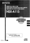
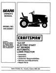
Figure 2 shows the snow thrower completely assembled.
References to the right or left hand side
of the snow thrower are from the viewpoint of the operator's position behind
the unit.
Auger Drive Lever
2 - 1/2 inch wrenches
(or adjustable wrenches)
2 - 9/16 inch wrenches
(or adjustable wrenches)
2 - 3/4 inch wrenches
(or adjustable wrenches)
1 - Pliers (to spread cotter pin)
1 - Screwdriver
n
Drive Lever
_'-_=..._
Shifter
ll_.====_=q
Lever __
1 - Measuring tape or ruler
÷r _
_Clutch
Traction
Cable
.
Crank Assembly
Deflector
Chute
Height
Adjust
Skd
Figure 1
Figure 1 shows the snow thrower in the
shipping position.
TO REMOVE
SNOW
THROWER
FROM CARTON
1. Locate all parts packed separately
and remove from the carton.
NOTE: Place fuel stabilizer in a
safe place until needed for storage.
2. Remove and discard the packing
material from around the snow
thrower.
3. Cut down all four corners of the carton and lay the panels flat.
4. For shipping purposes, the height
adjust skids are attached to the
pallet. Remove the screw that seF_)21084L
Figure 2
cures each height adjust skid to
the pallet. See Figure 2.
5. Roll snow thrower off the pallet by
pulling on the lower handle. CAUTION: DO NOT back over control
cables.
6.
Remove all packing material from
the unit.
7.
Cut ties securing the clutch control
cable to the lower handle and lay
cable back away from the motor
frame.
6.
TO ASSEMBLE
THE HANDLE AND
CRANK ASSEMBLY
1. Cut tie holding shift rod to lower
handle and move shifter to the first
forward gear.
2. Cut and discard the plastic tie that
secures the crank assembly.
3. Loosen, but do not remove, the
screws, flatwashers. Iockwashers,
and hex nuts in the upper holes of
the lower handle. See Figure 3.
4. Remove the fasteners and the eyebolt from the lower holes of the lower handle See Figure 5.
Install the fasteners that were removed in step 4. DO NOT tighten
until all bolts are in place.
Left Side Of -__\
Upper Handle
318" Nylon
RightHand Side
Of U
Loosen,
but do not
remove
Eye Bolt
Flatwasher
Figure 5
11/32"
Flatwasher
7. Attach the crank rod to the universal
joint assembly with the hair pin. See
Figure 6.
5/16"
Screw
8. Tighten nut on eye bolt. Make sure
eye bolt is properly aligned and the
crank can freely rotate.
Figure 3
9. Tighten all handle bolts.
NOTE: Make sure the cables are
not caught between the upper and
lower handle.
5.
Raise the upper handle into operating position.
NOTE: If the cables have become disconnected form the drive levers, reinstall the cables as shown in Figure 4.
Lever
"Z" Fitting
Crank Rod
Figure 6
Control Cable
F_)2tO84L
Figure 4
8
NOTE: If the cables have become disconnected, connect cables as shown in
Figure 7.
Traction Drive Cable
Auger Drive Cable
Figure 7
HOW TO SET THE SKID HEIGHT
Your snow thrower is equipped with
height adjust skids on the outside of the
auger housing. To adjust the skid
height for different conditions, see To
Adjust Skid Height paragraph in the
Service And Adjustment section.
HOW TO SET THE LENGTH OF THE CABLES
The cables were adjusted at the factory
and no adjustments should be necessary. However, after the handles are put
in the operating position, the cables can
be too tight or too loose. If an adjustment is necessary, see "How To Check
And Adjust The Cables" in the Service
And Adjustment section.
_- CHECKLIST
While learning how to use your snow
thrower, pay extra attention to the following important items:
Before you operate your new snow
thrower, to ensure that you receive the
best performance and satisfaction from
this quality product, please review the
following checklist:
_" Engine oil is at proper level.
_" Make sure gas tank is filled properly
with clean, fresh, unleaded gasoline.
_" Become familiar with all controlstheir location and function. Operate
controls before starting engine.
_" All assembly instructions have been
completed.
_" The discharge chute rotates freely.
_" No remaining loose parts in carton.
F_)21084L
9
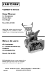
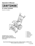
KNOW YOUR SNOW
THROWER
READ THiS OWNER'S MANUAL AND SAFETY RULES BEFORE OPERATING
YOUR SNOW THROWER. Compare the illustrations with your SNOW THROWER
to familiarize yourself with the location of various controls and adjustments. Save
this manual for future reference.
Electric
Start
Button
Auger
Drive Lever
(right hand)
(left hand)
Primer
ignition
Switch
3ox Gas
Cap
Crank
Assembly
,J
Chute
Deflector
Discharge
Chute
Gas
Tank
Choke
Control
Throttle
Control
Recoil
Starter
Handle
Height
Adjust
Skid
Shear Pin
Scraper Bar
Figure 8
Auger Drive Lever - Starts and stops
the auger and impeller (snow gathering
and throwing)
Traction Drive Lever - Propels the
snow thrower forward and in reverse.
Recoil Starter Handle - Starts the engine manually.
Speed Shitter Lever - Selects the
speed of the snow thrower (6 speeds forward and 2 speeds reverse).
Crank Assembly - Changes the direction of snow throwing through the discharge chute.
Chute Deflector - Changes the distance
the snow is thrown.
Primer Button - Injects fuel directly into
the carburetor manifold for fast starts in
cold weather.
Discharge Chute - Changes the height
and direction the snow is thrown.
Shear Pin - Shear pins are designed to
break (to protect the machine) if,an object becomes lodged in the auger housing.
Choke Control
engine.
Throttle Control
speed.
- Used to start a cold
- Controls the engine
Electric Start Button - (if so equipped)
Used to start the engine usingthe 120 V
electric starter.
Height Adjust Skid - Ad usts the ground
clearance of the auger housing.
Ignition Key - Must be inserted to start
Toolbox - Spare shear pins and spacers
are located in toolbox.
the engine.
10
F_)21084L
Theoperation
ofanysnowthrower
can
resultinforeignobjects
beingthrown
intotheeyes,whichcanresultinsevereeyedamage.Always
wearsafety
glasses
oreyeshields
whileoperating
thesnowthrower.
Werecommend
standard
safety
glasses
orawidevisionsafetymaskfor
overyourglasses.
Speed 3 - Light
Speed 4 - Very Light
Speed 5,6 - Transport only
Engage the traction drive lever (left
hand). As the snow thrower starts
to move, maintain a firm hold on the
handles, and guide the snow thrower along the clearing path. Do not
attempt to push the snow thrower.
3. To move the snow thrower backward, move the speed shifter lever
right into first or second reverse and
engage the traction drive lever (left
hand).
TO STOP YOUR
SNOW
THROWER
1. To stop throwing snow, release the
auger drive lever.
2. To stop the wheels, release the
traction drive lever.
3. To stop the engine, push the
throttle control lever to off and pull
out the ignition key
SNOW
Speeds 1,2 - Wet, Heavy
2.
Manual
before
i_
WARNING:
Readoperating
Owner's
machine. Never direct discharge toward bystanders. Stop the
engine before unclogging discharge
chute or auger housing and before
leaving the machine.
TO CONTROL
the speed you desire by moving the
speed shifter lever left into the appropriate notches on the shift lever
plate:
IMPORTANT: Do not move the speed
shifter lever while the traction lever
is down.
TO THROW
DISCHARGE
1. Turn the chute control rod to set the
direction of the snow throwing.
2. Loosen the wing knob on the chute
deflector and move the deflector to
set the distance. Move the deflector
(Up) for more distance, (Down) for
less distance. Then tighten the
wing knob (See Figure 9).
SNOW
1. Push down the auger driver lever
(right hand).
2.
Release to stop throwing snow.
TO USE WHEEL LOCKOUT PIN
1,
The left hand wheel is secured to
the axle with a klick pin. This unit
was shipped with this klick pin in the
locked position (through wheel
hole). See Figure 10.
Klick Pin t
Figure9
HOW TO MOVE FORWARD
AND
BACKWARD
1. To shift, release the traction drive
lever (left hand) and move the
speed shifter lever to the speed you
desire. Ground speed is determined by snow conditions. Select
F_)21084L
Locked
Position
2-Wheel
Drive
Figure 10
11
2.
For ease of maneuverability in light
snow conditions, disconnect the
klick pin from the wheel locked
position and push into the single
wheel drive position (unlocked axle
hole only). See Figure 11.
2.
3.
Remove the oil fill cap/dipstick.
Check the oil.
If necessary, add oil until the oil
reaches the FULL mark on the oil fill
cap/dipstick (see Figure 12). Do not
add too much oil.
Oil Fill C_p/Dipstick
Klick Pin
%
Unlocked
Position " []
_
gle Wheel
Drive
O;)_y
Figure11
NOTE: Make sure that the klick pin is
in the single wheel drive position of the
axle only and not through the locked
position.
BEFORE
STARTING
4. Tighten the fill cap/dipstick securely
each time you check the oil level.
NOTE: S.A.E. 5W30 motor oil may be
used to make starting easier in areas
where temperature is consistently 20°F.
or lower.
THE ENGINE
1. Before you service or start the engine, familiarize yourself with the
snow thrower. Be sure you understand the function and location of all
controls.
2. Check the tension of clutch cable
before starting the engine. See To
Adjust The Control Cable paragraph in the Service & Adjustments section of this manual.
3. Be sure that all fasteners are tight.
4. Make sure the height adjust skids
are properly adjusted. See To Adjust Skid Height paragraph in the
Service & Adjustments section of
this manual.
5.
FILL GAS:
The engine is certified to comply with
California and US EPA emission regulations for ULGE (Utility or Lawn and Garden Equipment) engines, ULGE
engines are certified to operate on regular unleaded gasoline.
fuels
(calledAlcohol
gasoholblended
or
ARNING:
those using ethanol or
methanol) can attract moisture
which leads to separation and
formation of acids during storage.
Acidic gas can damage the fuel system of an engine while in storage.
_1
Check tire pressure (14-17
pounds), Do not exceed maximum
amount of pressure.
CHECK
NOTE: To avoid engine problems, the
fuel system must be emptied before
storage for 30 days or longer. Start the
engine and let it run until the fuel lines
and carburetor are empty. Use fresh
fuel next season. See the Storage
section in this manual for additional information.
Never use engine or carburetor cleaner
products in the fuel tank or permanent
damage may occur.
THE OIL:
NOTE: The engine was shipped from
the factory filled with oil. Check the level of the oil. Add oil as needed.
To Add Oil
1. Make sure the unit is level.
NOTE: Do not check the level of the
oil while the engine runs.
F_)2t084L
must be between
Full and Add
mark
Figure 12
12
Fillthefueltankonlywithafresh,
clean,unleaded
regular,
unleaded
premium,orreformulated
automotive
gasoline.DONOTuseleaded
gasoline.
Makesurethatthecontainer
youpour
thegasoline
fromiscleanandfreefrom
rustorotherforeignparticles.
Never
usegasoline
thatmaybestalefrom
longperiods
ofstorage
inthecontainer.
_lb
mable.
Always
use caution
ARNING:
Gasoline
is flamwhen handling or storing
equipped
three-wire
ARNING:with
Thea starter
is
power cord and plug and is
designed to operate on 120 volt AC
household current. It must be properiy grounded at all times to avoid
the possibility of electrical shock
which may be injurious to operator.
_1
•
•
gasoline.
• Do not fill fuel tank while snow
thrower is running, when it is hot,
or when snow thrower is in an enclosed area.
•
•
•
•
•
Keep away from open flame or an
electrical spark and do not smoke
while filling the fuel tank.
Never fill the tank completely. Fill
the tank to within 1/4"-1/2" from
the top to provide space for expansion of fuel.
Always fill fuel tank outdoors and
use a funnel or spout to prevent
spilling.
Make sure to wipe up any spilled
fuel before stating the engine.
Store gasoline in a clean, approved container and keep the
cap in place on the container.
•
•
TO STOP ENGINE
To stop engine, move the throttle control lever to "STOP" position and remove key. Keep the key in a safe
place. The engine will not start without
the key.
TO START ENGINE
Be sure that the engine has sufficient
oil. The snow thrower engine is
equipped with a 120 volt A.C. electric
starter and recoil starter. Before starting the engine, be certain that you have
read the following information.
F_)21084L
13
Follow all instructions carefully
as set forth in the "To Start Engine" section.
Determine that your house wiring
is a three-wire grounded system.
Ask a licensed electrician if you
are not sure. If your house wire
system is not a three-wire system,
do not use this electric starter under any conditions.
If your system is grounded and a
three-hole receptacle is not available at the point your starter will
normally be used, one should be
installed by a licensed electrician.
When connecting 120 volt AC
"Power Cord", always connect the
cord to the Switch Box on the engine first, then plug the other end
into the three-hole grounded receptacle. When disconnecting
"Power Cord", always unplug the
end in the three-hole grounded receptacle first.
How To Start A Cold Engine
1. Be sure auger drive and traction
drive levers are in the disengaged
(RELEASED) position.
2. Move throttle control to "FAST"
position.
3. Insert the ignition key into the ignition slot. Make sure it snaps into
place. Do not turn key.
4. Rotate choke knob clockwise to the
choke ON position.
5. (Electric Start) Plug the power cord
into the switch box on the engine.
Plug the other end of power cord
into a three-hole, grounded 120
VOLT, AC receptacle.
6, Pushtheprimerbutton
as specified below. Remove finger from
primer button between pushes.
Do not push if temperature
above 50 ° F (10 ° C),
Push two times if temperature is
50 ° F (10 ° C) to 15°F (-10 ° C).
Push four times if temperature is
below 15° F (-10 ° C).
Push five times if temperature is
below 0° F (-18 ° C).
7. (Electric Start) Push down on the
starter button until the engine
starts. Do not crank for more than
10 seconds at a time. This electric
starter is thermally protected. If
overheated it will stop automatically
and can be restarted only when it
has cooled to a safe temperature (a
wait of about 5 to 10 minutes is required).
8, (Recoil Start) Rapidly pull the recoil starter handle. Do not allow
the recoil starter handle to snap
back, Slowly return the recoil starter handle.
button. If the engine fails to start, follow
the Cold Start instructions.
FROZEN STARTER
If the starter is frozen and will not turn
engine:
1. Pull as much rope out of the starter
as possible.
2. Release the starter handle and let it
snap back against the starten Repeat until the engine starts.
To help prevent possible freeze-up of
recoil starter and engine controls, proceed as follows after each snow removal job.
1. With the engine running, pull the
starter rope hard with a continuous
full arm stroke three or four times.
Pulling of starter rope will produce a
loud clattering sound. This is not
harmful to the engine or starter.
2. With the engine not running, wipe all
snow and moisture from the carburetor cover in area of control levers.
Also move throttle control, choke
control, and starter handle several
times.
9,
If the engine does not start in 5 or 6
tries, See Difficult Starting in the
"Troubleshooting Table".
10. When the engine starts, move the
choke control to "112 choke" position. When engine runs smoothly,
move choke control to the off
Position.
11. (Electric Start) First disconnect
power cord from receptacle. Then,
disconnect the power cord from the
switch box.
gine
indoorsNever
or in run
enclosed,
WARNING:
enpoorly ventilated areas. En*
gine exhaust contains CARBON
MONOXIDE, AN ODORLESS AND
DEADLY GAS. Keep hands, feet,
hair and loose clothing away from
any moving parts on engine and
snow thrower.
_lb
12, Run engine at full throttle "FAST"
when throwing snow.
Allow the engine to warm up for several
minutes before blowing snow in temperatures below 0°F.
How To Start A Warm Engine
If restarting a warm engine after a short
shutdown, leave the choke lever in the
off position and do not push the primer
F_)21084L
14
•
The temperature of muffler and
nearby areas may exceed 150°F.
Avoid these areas.
•
DO NOT allow children or young
teenagers to operate or be near
snow thrower while it is operat*
ing.
HOW TO REMOVE OBJECTS
FROM AUGER
Release auger drive lever.
Move throttle lever to stop position.
Remove (do not turn) ignition key.
Disconnect spark plug wire.
Do not place your hands in the auger or discharge chute. Use a pry
bar.
to ARNING:
remove any
that may
Do item
not attempt
become lodged in auger
without taking the following precau*
tions:
_1
SNOW THROWING TIPS
1. For maximum snow thrower efficiency in removing snow, adjust ground
speed, NEVER the throttle. Go
slower in deep, freezing or wet
snow. If the wheels slips, reduce
forward speed. The engine is designed to deliver maximum performance at full throttle and should be
run at this power setting at all times.
2. Most efficient snow throwing is accomplished when the snow is removed immediately after if falls.
6.
7.
3.
For complete snow removal, slightly
overlap each path previously taken.
4. The snow should be discharged
down wind whenever possible.
5.
8.
9.
For normal usage, set the skids so
that the scraper bar is 1/8" above
the skids. For extremely hardpacked snow surfaces, adjust the
F_)21084L
15
skids upward so that the scraper
bar touches the ground.
On gravel or crushed rock surfaces,
set the skids at 1-1/4" below the
scraper bar. See To Adjust Skid
Height paragraph in the Service &
Adjustments section of this manual. Rocks and gravel must not be
picked up and thrown by the machine.
After the snow throwing job has
been completed, allow the engine to
idle for a few minutes, which will
melt snow and accumulated ice off
the engine.
Clean the snow thrower thoroughly
after each use.
Remove ice and snow accumulation
and all debris from the entire snow
thrower, and flush with water (if possible) to remove all salt or other
chemicals. Wipe snow thrower dry.
SERVICERECORDS
Fillin datesasyou
complete
regular
service.
Before
Each
Use
Often
Every Every Every
5
10
25
Each Before SERVICE
Hours Hours Hours Season Storage DATES
Chain Lubrication
_/
Change Engine Oil
_/
Remove
Fuel
_/
_/
* Adjust after 2 to 4 hours of use.
GENERAL
RECOMMENDATIONS
AFTER EACH USE
Run the machine to clear the auger
of snow.
The warranty on this snow thrower
does not cover items that have been
subjected to operator abuse or negligence. To receive full value from the
warranty, the operator must maintain
the snow thrower as instructed in this
manual.
To prevent freezing of the auger or
controls, remove all snow and slush
from the snow thrower.
Check for any loose or damaged
parts.
Tighten any loose fasteners.
Check and maintain the auger.
Check controls to make sure they
are functioning properly.
If any parts are worn or damaged,
replace immediately.
Some adjustments will need to be
made periodically to properly maintain
your snow thrower.
F_)21084L
16
PRODUCT
SPECIFICATIONS
HORSEPOWER
9 HP
DISPLACEMENT
19.34cu.in,
GASOLINE
CAPACITY
4 quarts
(unleaded)
OIL CAPACITY
(20 oz capacity)
5W30
SPARK PLUG:
Champion RJ19LIV
(Gap .030 in.) or
equivalent
VALVE CLEARANCE:
Intake: .010 In,
Exhaust: .010 In.
SNOW
Hexshaff
Figure 13
AUGER GEAR BOX
The auger gear box is lubricated at the
factory and should not require additional lubrication. If for some reason the
lubricant should leak out, have auger
gear case checked by a competent repairman.
THROWER
AUGER DRIVE BELT
ENGINE
Adjust the auger drive belt after the first
2 to 4 hours of use, again about midseason and twice each season thereafter (See to "Belt Adjustment"
in the
Service and Adjustment section),
LUBRICATION
Check the crankcase oil level before
starting the engine and after each five
(5) hours of continuous use. See
Figure 14. Add S.A.E. 5W30 motor oil
as needed. Tighten fill cap/dipstick securely each time you check the oil level.
CHAIN LUBRICATION
EVERY 25 HOURS
1. Position speed selector lever in first
(1) forward gear.
2. Stand the snow blower up on the
auger housing end.
NOTE: When the crank case if
filled with oil, do not leave the
snow blower standing up on the
auger housing for an extended
period of time.
3, Remove the bottom panel,
4, Lubricate the chains with a chain
type lubricant.
5. For storage, wipe the hexshaft and
sprockets with 5W30 motor oil.
NOTE: Clean all excess grease or
oil found on the rubber fricfion
wheel or the disc drive plate.
Oil Fill Cap/Di_,
Figure 14
Change the oil every twenty-five (25)
hours or at least once a year if the
snow thrower is not used for twentyfive (25) hours.
TO CHANGE ENGINE OIL
1. Position the snow thrower so that
the oil drain plug is at the lowest
point on the engine.
2. Remove the oil drain plug and the
oil fill cap/dipstick. Drain the oil
into a suitable container.
CAUTION: Do not allow grease or
oil to contact the rubber friction
wheel or the disc drive plate.
6. Install the bottom panel.
F_)21084L
17
NOTE: The oil will drain more freely
when the engine is warm.
3. After draining all the oil, reinstall the
oil drain plug securely.
4. Fill the engine crankcase with
S.A.E. 5W30 motor oil, pouring
slowly. DO NOT OVERFILL. See
"To Add Oil" in the Operation Section.
SPARK PLUG
3.
Check the spark plug every twentyfive (25) hours. Replace the spark plug
if the electrodes are pitted or burned or
if the porcelain is cracked.
Before installing the spark plug,
coat the threads lightly with oil for
easy removal. Tighten the spark
plug to a torque of 15 foot*pounds.
Feeler Gauge
O.03O"
1. Make sure the spark plug is clean.
Clean the spark plug by carefully
scraping the electrodes (do not
sand blast or use a wire brush).
2,
Check the spark plug gap with a
feeler gauge and reset gap to 0,30"
if necessary. See Figure 15.
F_:_21084L
Spark Plug
Figure 15
18
_.'_o_
V:__ I my:_m_ll_,_l i _vA
I_ _i i
raise the adjustable skids. Tighten
the mounting nuts. See Figure 16.
NOTE: For rocky or uneven surfaces,
raise the front of the snow thrower by
moving the skids down.
nect
the spark
plug disconwire and
ARNING:
Always
place it where it cannot
make contact with spark plug to prevent accidental starting when making any adjustments or repairs.
_l=lb
maintain
groundto
WARNING:proper
Be certain
clearance for your particular
area to be cleared. Objects such as
gravel, rocks or other debris, if
struck by the impeller, may be
thrown with sufficient force to cause
personal injury, property damage or
damage to the snow thrower.
_lb
TO ADJUST
SKID HEIGHT
This snow thrower is equipped with two
height adjustment skids, located on
the outside of the auger housing. See
Figure 16.
These skids elevate the front of the
snow thrower.
Mountin
TO ADJUST
Nuts
1. Position the snow thrower on a level
surface.
Height Adjust Skid
Figure 16
2,
Make sure both tires are equally inflated. Proper tire pressure is 14 to
17 PSI. See side of tire for maximum inflation. Do not exceed maximum sidewall pressure on tire.
3,
Loosen the carriage bolts and nuts
securing the scraper bar to the auger housing.
For normal hard surfaces, such as a
paved driveway or walk, adjust the
skids as follows.
1. Position the snow thrower on a level
surface.
2.
Make sure both tires are equally inflated. Proper tire pressure is 14 to
17 PSI. See side of tire for maximum inflation. Do not exceed maximum sidewall pressure on tire.
4. Adjust the scraper bar to the proper
position.
5. Tighten the carriage bolts and nuts,
making sure that the scraper bar is
parallel with the working surface.
3. Place the extra shear bolts supplied
(found in parts bag) under each
end of the scraper bar next to the
adjustable skids.
4. Loosen the mounting nuts that hold
the adjustable skids. To bring the
front of the snow thrower down,
F_)21084L
BAR
After considerable use, the metal scraper bar will have a definite wear pattern,
The scraper bar in conjunction with the
skids should always be adjusted to allow 1/8" between the scraper bar and
the sidewalk or area to be cleaned.
O
Auger t-
SCRAPER
6.
19
For extended operation, the scraper
bar may be reversed. If the scraper
bar must be replaced due to wear,
remove the carriage bolts and nuts
and install a new scraper ban
_.'_o_
V:__ I my:_m_ll_,_l i _vA
I_ _i i
BELT ADJUSTMENT
5.
Traction Drive Belt
The traction drive belt has constant
spring pressure and does not require
an adjustment. If the traction drive belt
is slipping, replace the belt. See "How
To Replace The Belts" in the Service
And Adjustment section.
Have someone engage auger drive
clutch. Check tension on belt (opposite idler pulley). Belt should deflect about 1/2 inch (12.5 mm) with
moderate pressure (Figure 18). You
may have to move idler pulley more
than once to obtain the correct tension.
Auger
(
Auger Drive Belt
If your snow blower will not discharge
snow, check the control cable adjustment. If it is correct, then check the
condition of the auger drive belt. If it is
damaged or loose, replace it (see "How
To Replace The Belts" in this section of
the manual).
ve
/Idler __.._-('/c
Pulley
7oJ
Engaged /_
--j_ _
J _t\0
\_
.7\_ s_
"
Pulley
1/2 inch
(12.5turn)
Deflection
"_
_
1. Disconnect spark plug wire.
2.
Remove screw from belt cover.
Remove belt cover (see Figure 17),
Figure 18
6.
Reinstall belt cover.
7. Whenever belts are adjusted or replaced, the cables will need to be
adjusted. (See Cable Adjustment in
this section of the manual).
8. Attach the spark plug wire.
HOW TO REPLACE THE BELTS
The drive belts are of special construction and must be replaced with original
equipment replacement belts available
from your nearest Sears service center.
Some steps require the assistance of a
second person.
3.
How To Remove the Auger Drive Belt
If the auger drive belt is damaged, the
snow thrower will not discharge snow.
Replace the damaged belt as follows.
1. Disconnect the spark plug wire.
2. Loosen the bolts on each side of
the bottom panel (see Figure 19).
Loosen nut on auger idler pulley
and move auger idler pulley towards
belt about 1/8 inch (3 ram) (see
Figure 20).
4. Tighten nut.
F_)21084L
2O
_.'_o_
3,
Remove
the bottom
V:__ I my:_m_ll_,_l i _vA
I_ _i i
from the engine pulley. Replace
the auger drive belt with an original
equipment replacement belt available from a Sears service center,
panel.
Bolt
Bottom
Panel
8,
Install the new auger drive belt
onto the auger drive pulley and
onto pulley.
9, Adjust the auger drive belt, See
"How To Adjust The Auger Drive
Belt" in the Service And Adjustment
section,
Auger
Housing
10, Adjust the belt guide. See "How To
Adjust The Belt Guide" in the Service And Adjustment section.
11, Install the belt cover. Tighten
screw (See Figure 17).
12, Check the adjustment of the cables.
See "How To Check And Adjust The
Cables" in the Service And Adjustment section.
Figure 19
4,
Remove screw from belt cover.
Remove the belt cover (see
Figure 17).
5, Loosen the belt guide. Pull the belt
guide away from the auger drive
pulley (see Figure 20).
6, Pull the idler pulley away from the
auger drive belt,
7, Remove the old auger drive belt
from the auger drive pulley and
13, Install the bottom panel (see
Figure 19).
14, Tighten the bolts on each side of
the bottom panel.
15, Connect the spark plug wire,
_
Traction Drive Be,t
Engine Pulley
Belt Guide
Auger Drive Pulley
Traction Drive
'\
_r
Ib_
Auger Idler Pulley
Auger Drive Belt
Traction Drive
Spdng
Traction
Drive Belt
E-Ring
Traction
Drive Pulley
Swing Plate
Axle Rod
Engine
Pulley
Figure 20
F_)2tO84L
21
How To Remove
The Traction Drive Belt
plate is properly secured (see
Figure 21).
If the snow thrower will not move forward, check the traction drive belt for
wear or damage. If the traction drive
belt is worn or damaged, replace the
belt as follows.
1. Disconnect the spark plug wire.
IIII
2. Remove the auger drive belt. See
"How To Remove The Auger Drive
Belt" in the Service And Adjustment
section.
3.
Remove the e-ring from one end of
the swing plate axle rod. Remove
the swing plate axle rod to allow
the swing plate to pivot forward (see
Figure 20).
4.
Remove the traction drive spring.
5.
Remove the old traction drive belt
from the tractiOn drive pulley and
from the engine pulley Replace
the traction drive belt with an original equipment replacement belt
available from a Sears service center.
6.
7.
Install the new traction drive belt
onto the traction drive pulley and
onto engine pulley,
Make sure the traction drive idler
pulley is properly aligned with the
traction drive belt.
8. Attach the traction drive spring.
9.
Install the swing plate axle rod and
secure with the e-ring removed
earlier.
Alignment
Tabs
Figure 21
NOTE: If the drive will not engage
after the traction drive belt has
been replaced, then check to
make sure that the swing plate is
positioned between the alignment tabs.
11. Install and adjust the auger drive
belt. See "How To Remove The Auger Drive Belt" in the Service And
Adjustment section.
12. Adjust the belt guide. See "How To
Adjust The Belt Guide" in the Service And Adjustment section.
13, Install the bottom panel (see
Figure 19).
14. Tighten the bolts on each side of
the bottom panel.
15. Install the belt cover. Tighten
screw (see Figure 17).
16. Check the adjustment of the cables.
See "How To Check And Adjust The
Cables" in the Service And Adjustment section.
10. The bottom of the swing plate must
be positioned between the align17. Connect the spark plug wire.
ment tabs. Make sure the swing
F_21084L
22
_.'_o_
BELT
GUIDE
!:I _ I mI:1 m_[l_,_l i _vA
I_ _i i
ADJUSTMENT
"Z" Fitting
1. Remove spark plug wire.
2. Have someone engage auger drive.
3. Measure the distance between the
belt guide and belt. The distance
should be 1/8 inch (3.175 mm) for
guide. See Figure 22.
Figure 23
__
Auger Idler_ i_a_
Pulley _ t'' d
Oa/
-
Belt Guide
2. The center of the "Z" fitting should
be between the center and top of
the hole in the clutch lever. Adjust
either the auger drive cable or the
traction drive cable as as necessary
according to the following instructions.
\\
\\
Engaged __@__
_
Auger Drive Cable Adjustment
Figure 22
4.
If adjustment is necessary, loosen
belt guide mounting bolt. Move belt
guide to the correct position. Tighten mounting bolt.
5. Reinstall belt cover.
6.
1. Run the engine until the fuel tank is
empty and the engine stops.
2.
Stand the snow thrower up on the
front end of the auger housing.
3.
Push cable through spring to expose the threaded portion of the
cable (see Figure 24).
Reconnect spark plug wire.
HOW TO CHECK AND
ADJUST THE CABLES
The cables are adjusted at the factory
and no adjustment should be necessary. If the cables have become
stretched or are sagging adjustment will
be necessary.
Whenever belts are adjusted or replaced, the cables will need to be adjusted.
Square
End
Cable Spring
Locknut
To check for correct adjustment, un_
hook "Z" fitting at clutch lever (see
Figure 24
Figure 23),
1. Move clutch lever to the full forward
4. Hold square end of threaded portion
position (just contacting plastic
with pliers and adjust Iocknut in or
bumper). Holding cable tight, note
out until correct adjustment is
position of fitting to hole in clutch lereached. Pull cable back through
veR
spring and connect cable.
23
F_)21084L
_.'_o_
B_ I my:1m_[l_,_l i_vA
I_ _i i
TRACTION
DRIVE CABLE ADJUSTMENT
1, Run the engine until the fuel tank is
7, Push the bottom of the traction
empty and the engine stops.
Stand the snow thrower up on the
front end of the auger housing,
3, Loosen the bolts on each side of
the bottom panel (see Figure 25).
drive cable through the cable adjustment bracket until the "Z"
hook can be removed.
8, Remove the "Z" hook from the
cable adjustment bracket. Move
the "Z" hook down to the next adjustment hole.
9, Pull the traction drive cable up
through the cable adjustment
bracket.
10, Put the cable boot over the cable
adjustment bracket.
11, install the "Z" hook to the traction
drive lever (see Figure 23).
12, To check the adjustment, depress
the drive lever and check the length
of one of the drive springs, in correct adjustment, the length of the
drive spring is:
minimum 3" (76 mm,)
maximum 3-3/8" (85 mm.)
(see Figure 27).
2,
Bolt
Bottom Panel
Auger
Housing
'\ \ Bolt
_._
Figure25
4,
5,
6,
Remove the bottom panel.
Disconnect the "Z" fitting from the
drive lever (see Figure 23).
Slide the cable boot off the cable
adjustment bracket (see
Figure 26).
Drive Cable
Figure 27
Tracti°t_i_/
Cable Boo
Cable Adjustment /_
Bracket
F_)21084L
"Z" Hook
Figure 26
24
_.'_o_
V:__ I my:_m_ll_,_l i _vA
I_ _i i
HOW TO ADJUST OR REPLACE
THE FRICTION WHEEL
5.
Install the bottom panel (see
Figure 28).
6. Tighten the bolts on each side of
the bottom panel.
How To Check The Friction Wheel
Bolt
If the snow thrower will not move forward, check the traction drive belt, the
traction drive cable or the friction wheel.
If the friction wheel is worn or damaged,
it must be replaced. See "How To Replace the Friction Wheel" in this section.
If the friction wheel is not worn or damaged, check as follows.
Auger
Housing
1. Run the engine until the fuel tank is
empty and the engine stops.
2.
3,
4,
Bolt
Stand the snow thrower up on the
front end of the auger housing
(see Figure 28).
'_\
Figure28
Disconnect the spark plug wire,
Loosen the bolts on each side of
the bottom
panel (see Figure 28).
5.
Remove the bottom panel.
6.
Position the shift speed lever in
the lowest forward speed.
7.
Note the position of the friction
wheel (see Figure 29). The correct
distance "A" from the right side of
the friction wheel to the outside of
the motorbox is as follows:
Tire Size
Distance "A"
12 and 13 inch
4-1/8"
16 inch
4-5/16"
If the friction wheel is not in the
correct position, adjust according to
the following instructions.
Figure 29
Speed Control Rod
_Bolts
How To Adjust The Friction Wheel
1. Position the shift speed lever in
the lowest forward speed.
2.
3.
Bottom Panel
Loosen the bolts
control rod (see
Move the friction
rect position (see
on the
Figure
wheel
Figure
speed
30).
to the cor29).
4. Tighten the bolts on the speed
control red (see Figure 30).
F_)21084L
_7
--
Figure 30
25
_.'_o_
V:__ I my:_m_ll_,_l i _vA
I_ _i i
How To Replace The Friction Wheel
If the friction wheel is worn or damaged,
the snow thrower will not move forward.
The friction wheel must be replaced as
follows.
1. Run the engine until the fuel tank is
empty and the engine stops.
Bottom Panel
Wheel
Figure 31
2.
Stand the snow thrower up on the
front end of the auger housing (4).
(see Figure 28).
3.
Disconnect the spark plug wire.
4.
Remove the fasteners that secure
the right wheel. Remove the right
wheel from the axle (see Figure 31)
5.
Loosen the bolts on each side of
the bottom panel,
6.
Remove the bottom panel,
Chain
7.
Remove the fasteners that secure
the drive sprocket to the axle (see
Figure 32).
8.
Remove the left wheel, axle, and
drive sprocket.
9.
Remove the four bolts that hold the
bearings on each side of the hex
shaft (see Figure 33).
Figure 32
Bolts
10. Remove the hex shaft and bear*
ings.
Figure 33
NOTE: Take special note of the position of the washers on the hex shaft.
F_)21084L
26
_.'_o_
V:__ I my:_m_ll_,_l i _vA
I_ _i i
11. Remove the three fasteners that
hold the friction wheel to the hub
(see Figure 34).
17. Check the adjustment of the friction
wheel. See "How To Adjust The
Friction Wheel" in this section.
18. Make sure the friction wheel and the
12. Remove the friction wheel from the
hub. Slip the friction wheel off the
hex shaft.
disc drive plate are free from grease
or oil.
19. Install the bottom panel (see
Figure 31).
13. Assemble the new friction wheel
onto hub with the fasteners re*
moved earlier.
20. Tighten the bolts on each side of
the bottom panel.
14. Install the hex shaft and bearings
with the four bolts removed earlier
(see Figure 35).
21. Install the right wheel to the axle
with the fasteners removed earlier.
22, Connect
Make sure the washers are prop*
erly installed in the original posi*
tion. Also, make sure the two
washers are properly aligned
with the actuator arms.
the spark
plug wire,
Fasteners
Hub
Friction
Wheel
Hex Shaft
15. Make sure the hex shaft turns free]y.
16. Install the left wheel, axle, and
drive sprocket with the fasteners
removed earlier, install the chain
onto the drive sprocket (see
Figure 32).
Fasteners
Figure 34
Beanngs
Actuator Arms
/
Bearings
Washer
Washer
\
Washer
F_)21084L
27
Figure 35
_.'_o_
HOW TO REPLACE
THE AUGER SHEAR
f:1_ I my:1m_[l_,_l i _vA
I_ _i i
2.
BOLT
The augers are secured to the auger
shaft with special shear bolts. These
shear bolts are designed to break and
protect the machine if an object becomes lodged in the auger housing. Do
not use a harder bolt as the protection
provided by the shear bolt will be lost.
Disconnect the spark plug wire.
Make sure all moving parts have
stopped.
3. Align the hole in the auger with the
hole in the auger shaft. Install the
new shear pin and spacer. See
Figure 36.
4.
protect
the machine,
ARNING:
For safety use
and to
only original equipment
shear bolts.
To replace a broken shear bolt, proceed
as follows. Extra shear bolts were provided in the assembly parts bag.
Connect the spark plug wire.
_lb
._
1. Move the throttle control to the stop
position. Disengage all controls.
TO ADJUST
_/?
_
"_
_ Shear Pin
_/Spalce r
_Figure 36
THE CARBURETOR
If you think your carburetor needs adjusting, contact your nearest Sears Service Center. Engine performance
should not be affected at altitudes up to
7,000 feet. For operation at higher
elevations, contact your nearest Sears
Service Center
the engine above the factory high
speed setting can be dangerous. If you
think the engine-governed high speed
needs adjusting, contact your nearest
Sears Service Center, which has the
proper equipment and experience to
make any necessary adjustments. For
the location of the nearest Sears Service Center, call Sears Service at
1-800-4-MY-HOME®.
IMPORTANT:
Never tamper with the
engine governor, which is factory set for
proper engine speed. Over-speeding
F_)21084L
"'
28
l.'Jll
snow
thrower
indoors
in
il_
WARNING:
Never
store oryour
an enclosed, poorly ventilated area. If gasoline remains in the
tank, fumes may reach an open
flame, spark or pilot light from a furnace, water heater, clothes dryer,
cigarette, etc.
1,
Run the engine until the fuel tank is
empty and the engine stops.
2.
If you do not remove the gasoline,
use fuel stabilizer supplied with unit
or purchase Craftsman Fuel Stabilizer No. 3550. Add fuel stabilizer to
any gasoline left in the tank to minimize gum deposits and acids. If the
fuel tank is almost empty, mix stabilizer with fresh gasoline in a separate container and add some to the
fuel tank.
To prevent damage (if snow thrower is
not used for more than 30 days) follow
the steps below.
SNOW THROWER
1, Thoroughlyclean the snow thrower,
2, Lubricate all lubrication points. See
the Maintenance section,
3.
Be sure that all nuts, bolts and
screws are securely fastened. Inspect all visible moving parts for
damage, breakage and wean Replace if necessary.
3,
Always follow the instructions on the
stabilizer container. After the stabilizer is added to the fuel tank, run
the engine at least ten minutes to
allow the mixture to reach the carburetor.
4,
Change the engine oil.
5.
Lubricate the piston/cylinder area.
First, remove the spark plug and
squirt a few drops of clean engine
oil into the spark plug hole. Next,
cover the spark plug hole with a rag
to absorb oil spray. Then, pull two or
three times on the recoil starter rope
to rotate the engine. Finally, install
the spark plug and attach the spark
plug wire.
4. Touch up all rusted or chipped paint
surfaces; sand lightly before painting.
5.
Cover the bare metal parts of the
blower housing auger and the impeller with rust preventative, such
as a spray lubricant.
NOTE: A yearly checkup or tune-up by
a Sears service center is a good way of
ensuring that your snow thrower will
provide maximum performance for the
next season.
OTHER
1, If possible, store your snowthrower
indoors and cover it to give protection from dust and dirt.
ENGINE
Gasoline must be removed or treated to
prevent gum deposits from forming in
the fuel tank, filter, hose, and carburetor
during storage. Also, during storage alcohol blended gasoline that uses ethanol or methanol (sometimes called
gasohol) attracts water. It acts on the
gasoline to form acids which damage
the engine.
F_)21084L
2.
If the snow thrower must be stored
outdoors, put the snow thrower on
blocks to raise it off of the ground.
3. Cover the snow thrower with a suitable protective cover that does not
retain moisture. Do not use plastic.
IMPORTANT: Never cover snow
thrower while engine and exhaust areas
are still warm.
29
il;Tell:J_]_'_[eZe_ll_[e]
TROUBLE
CAUSE
CORRECTION
Difficult starting
Defective spark plug.
Replace spark plug.
Water or dirt in fuel system,
Remove fuel from fuel tank.
Add fresh fuel.
Engine runs erratically
Blocked fuel line, empty gas
tank, or stale gasoline
Clean fuel line; check fuel
supply; add fresh gasoline
Engine stalls
Unit running on CHOKE.
Set choke lever to OFF
position.
Engine runs erratic;
Loss of power
Water or dirt in fuel system.
Remove fuel from fuel tank.
Add fresh fuel.
Excessive
Loose parts: damaged
impeller
Immediately stop engine.
Remove ignition key. Tighten
all fasteners and make all
necessary repairs. If
vibration continues, take the
unit to a Sears service
center.
Traction drive belt loose or
damaged.
Replace traction drive belt.
Incorrect adjustment of
traction drive cable
Adjust traction drive cable.
Worn or damaged friction
wheel.
Replace friction wheel.
Auger drive belt loose or
damaged.
Adjust auger drive belt;
replace if damaged.
Auger control cable not
adjusted correctly.
Adjust auger control cable.
Shear bolt broken
Replace shear bolt
Discharge chute clogged.
Stop engine immediately and
disconnect spark plug wire.
Clean discharge chute and
inside of auger housing.
Foreign object lodged in
auger
Stop engine immediately and
disconnect spark plug wire.
Remove object from auger.
vibration
Unit fails to propel
itself
Unit fails to discharge
snow
F_)21084L
30
SEARS,
ROEBUCK
AND CO.
Federal and California Emission Control Systems Limited Warranty
Small Off-Road Engines
CALIFORNIA & US EPA EMISSION
CONTROL WARRANTY STATEMENT
The U. S. Environmental Protection Agency
("EPA"), the California Air Resources Board
("CARB") and Sears, Roebuck and Co. are
pleased to explain the Federal and California
Emission Control Systems Warranty on your
new small off-roed engine. In California, new
1995 and later small off-road engines must be
designed, built and equipped to meet the
State's stringent anti-smog standards. In other states, new 1997 and later model year engines must be designed, built and equipped, at
the time of sale, to meet the U.S. EPA regulations for small non-roed engines. Sears, Roebuck and Co. will warrant the emission control
system on your small off-roed engine for the
periods of time listed below, provided there
has been no abuse, neglect, unapproved modification, or improper maintenance of your
small off-road engine.
Your emission control system may include
parts such as the carburetor, ignition system
and exhaust system. Also included may be the
compression release system and other emissiom-related assemblies.
Where a warrantable condition exists, Sears,
Roebuck and Co. will repair your small offroad engine at no cost to you for diagnosis,
parts and labor.
MANUFACTURER'S EMISSION
CONTROL SYSTEM WARRANTY
COVERAGE
Emission control systems on 1995 and later
model year California small off-road engines
are warranted for two years as hereinafter
noted. In other states, 1997 and later model
year engines are also warranted for two years.
If, during such warranty period, any emissionrelated part on your engine is defective in materials or workmanship,
the part will be
repaired or replaced by Sears, Roebuck and
Co.
OWNER'S WARRANTY
RESPONSIBILITIES
As the small off-roed engine owner, you are
responsible for the performance of the re31
F_)21084L
quired maintenance
Manual, but Sears,
deny warranty solely
or for your failure to
of the performance
nance.
listed in your Owner's
Roebuck and Co. will not
due to the lack of receipts
provide written evidence
of all scheduled mainte-
As the small off-road engine owner, you
should, however, be aware that Sears, Roebuck and Co. may deny you warranty coverage if your small off-road engine or a part
thereof has failed due to abuse, neglect, improper maintenance or unapproved modifications.
You are responsible for presenting your small
off-roed engine to a Sears, Roebuck and Co.
Authorized Service Outlet as soon as a problem exists. The warranty repairs should be
completed in a reasonable amount of time, not
to exceed 30 days.
Warranty service can be arranged by contacting either a Sears, Roebuck and Co. Authorized Service Outlet, or by contacting Sears,
Roebuck and Co. at 1-800473-7247.
IMPORTANTNOTE
This warranty statement explains your rights
and obligations under the Emission Control
System Warranty "(ECS Warranty") which is
provided to you by Sears, Roebuck and Co.
pursuant to California law. See also the Sears,
Roebuck and Co. Limited Warranties for
Sears, Roebuck and Co. which is enclosed
therewith on a separate sheet and also is provided to you by Sears, Roebuck and Co. The
ECS Warranty applies only to the emission
control system of your new engine. To the extent that there is any conflict in terms between
the ECS Warranty and the Sears, Roebuck
and Co. Warranty, the ECS Warranty shall apply except in any circumstances in which the
Sears, Roebuck and Co. Warranty may provide a longer warranty period. Both the ECS
Warranty and the Sears, Roebuck and Co.
Warranty describe important rights and obligations with respect to your new engine.
Warranty service can only be performed by a
Sears, Roebuck and Co. Authorized Service
Outlet. At the time of requesting warranty service, evidence must be presented of the date
of sale to the edginal purchaser. The purchas-
ershallpayanycharges
formaking
service Sears, Roebuck and Co. according to Subseccallsand/or
fortransporting
theproducts
to tion 4 below. Any such part repaired or reandfromtheplace
where
theinspection
and/ placed under the ECS Warranty shall be
orwarranty
work
isperformed.
Thepurchaserwarranted for any remainder of the ECS Warshallberesponsible
foranydamage
orlossin- ranty Period.
curred
inconnection
withthetransportation
of
warranted,
emissions-related
part
anyengine
oranypart(s)
thereof
submitted
for 2.whichAnyis scheduled
only for regular inspection
inspection
and/or
warranty
work.
as specified in the Owner's Manual shall be
Ifyouhave
anyquestions
regarding
your
war- warranted for the ECS Warranty Period. A
rantyrightsandresponsibilities,
youshould statement in such written instructions to the efcontactSears,Roebuck
and Co. at fect of "repair or replace as necessary", shall
not reduce the ECS Warranty Period. Any
1-800-473-7247.
EMISSION CONTROL SYSTEM
WARRANTY
Emission Control System Warranty ("ECS
Warranty") for 1995 and later model year California small off-road engines (for other states,
1997 and later model year engines):
A. APPLICABILITY: This warranty shall apply
to 1995 and later model year California small
off-road engines (for other states, 1997 and
later model year engines). The ECS Warranty
Period shall begin on the date the new engine
or equipment is delivered to its odginal, enduse purchaser, and shall continue for 24 consecutive months thereafter.
such part repaired or replaced under the ECS
Warranty shall be warranted for the remainder
of the ECS Warranty Period.
3. Any warranted,
emissions-related
part
which is scheduled for replacement as required maintenance in the Owner's Manual,
shall be warranted for the period of time pdor
to the first scheduled replacement point for
that part. If the part fails prior to the first scheduled replacement, the part shall be repaired or
replaced by Sears, Roebuck and Co. according to Subsection 4 below. Any such emissions-related part repaired or replaced under
the ECS Warranty, shall be warranted for the
remainder of the ECS Warranty Period prior to
the first scheduled replacement point for such
emissions-related
part.
B. GENERAL
EMISSIONS
WARRANTY
COVERAGE: Sears, Roebuck and Co. warrants to the original, end-use purchaser of the
new engine or equipment and to each subsequent purchaser that each of its small off-road
engines is:
4. Repair or replacement of any warranted,
emissions-related
part under this ECS Warranty shall be performed at no charge to the
owner at a Sears, Roebuck and Co. Authorized Service Outlet.
1. Designed, built and equipped so as to conform with all applicable regulations adopted by
the Air Resources Board pursuant to its authodty in Chapters 1 and 2, Part 5, Division 26
of the Health and Safety Code, and
5. The owner shall not be charged for diagnostic labor which leads to the determination that
a part covered by the ECS Warranty is in fact
defective, provided that such diagnostic work
is performed at a Sears, Roebuck and Co. Authorized Service Outlet.
2. Free from defects in materials and workmanship which, at any time during the ECS
Warranty Pedod, will cause a warranted emissions-related
part to fail to be identical in all
material respects to the part as described in
the engine manufacturer's application for certification.
C. The ECS Warranty only pertains to emissions-related parts on your engine, as follows:
1. Any warranted, emissions-related
parts
which are not scheduled for replacement as
required maintenance in the Owner's Manual
shall be warranted for the ECS Warranty Period. If any such part fails dudng the ECS Warranty Period, it shall be repaired or replaced by
32
F_)2t084L
6. Sears, Roebuck and Co. shall be liable for
damages to other original engine components
or approved modifications proximately caused
by a failure under warranty of an emission-related part covered by the ECS Warranty.
7. Throughout the ECS Warranty Period,
Sears, Roebuck and Co. shall maintain a supply of warranted emission-related
parts sufficient to meet the expected demand for such
emission-related
parts.
8. Any Sears, Roebuck and Co. authodzed
and approved emission-related
replacement
part may be used in the performance of any
ECS Warranty maintenance or repair and will
be provided without charge to the owner. Such
EMISSION-RELATED
PARTS
useshallnotreduce
Sears.
Roebuck
andCo.
ECSWarranty
obligations.
INCLUDE
THE FOLLOWING:
9.Unapproved
add-on
ormodified
parts
may 1. Carburetor Assembly and its Internal Comnotbeused
tomodify
orrepair
aSears,
Roe- ponents
buck
andCo.engine.
Such
usevoids
thisECS a) Fuel filter
Warranty
andshallbesufficient
grounds
for
Carburetor gaskets
disallowing
anECSWarranty
claim.
Sears, b)
Roebuck
andCo.shall
notbeliable
hereunderc) Intake pipe
forfailures
ofanywarranted
parts
ofaSears, 2. Air Cleaner Assembly
Roebuck
andCo.engine
caused
bytheuseof a) Air filter element
such
anunapproved
add-on
ormodified
part. 3. ignition System. including:
a) Spark plug
b) Ignition module
c) Flywheel assembly
4. Catalytic
Muffler (if so equipped)
a) Muffler gasket (if so equipped)
b) Exhaust manifold (if so equipped)
5. Crankcase
Components
Breather Assembly and its
a) Breather connection
tube
10/22/99 EPA/CARB
Sears, Roebuck and Co., Hoffman
F_)2t084L
33
Estates, IL 60179 U.S.A.
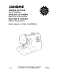
CRAFTSMAN
9HP SNOW THROWER
ENGINE
6
536.887991
20
25-2
22
24
!6
8
18
25-3
23
\
12
\
25-2
/
25-5
/
olz25-
/
14
Re£Ddve Page
3
Ref. Auger Housing Page
Key
No.
Key
No.
Part No.
Description
Part No.
Description
2
143.039005
ENGINE (762132)
22
71060
WASHER
3
002x97
BOLT, CARRIAGE
23
1501482
5
028x64
RETAINER,
PLATE, ANTI
VIBRATION
6
710026
NUT
24
910828
SCREW
25
1801103E549
FRAME ASSEMBLY
25-1
1501062E549
PLATE, ENGINE
25-2
310169
SCREW
25-3
780055
SCREW
25-4
1501049E549
MOTOR BOX
25-5
26x263
SCREW
F-021084L
MANUAL
8
10
12
14
16
18
1501109
710247
71063
71015
579932
585416
20
1501201
F_)21084L
PUSH
PULLEY, ENGINE
WASHER
WASHER
SCREW
BELT, V
BELT, V
--
GUIDE, ROD BELT
34
CRAFTSMAN
9HP SNOW THROWER
536.887991
ELECTRIC STARTER
8
9
7
\
ES100A
Key No.
F_)21084L
Part No.
Description
6
6218
MOTOR,
7
6216
SCREW
8
6217
SCREW
9
6219
CORD, STARTER
35
STARTER
CRAFTSMAN
9HP SNOW THROWER
FRAME
536.887991
169
170
160
/
106
162
\ lO5
lO8_
1
111
Re£ Auger
Housing
Page
120qo
Re£ Drive
Page
91
/
9O
168
91
103
149
107
Key
No.
Part No.
Description
Key
No.
Part No.
Description
90
1501055E701
COVER, BOTTOM
118
71060
WASHER,
SPLIT
91
310169
SCREW
122
780055
SCREW, TAP
103
1501226YZ
IDLER, AUGER
145
165x164
SPRING
105
711682
PIN, HAIR
148
50793
PULLEY, IDLER
106
761761
PIN, CLEVIS
149
590
NUT, JAM
107
165x159
SPRING, TENSION
160
1501052
COVER, BELT
108
781675 YZ
SPRING ATTACH
162
28X306
SCREW, TAP
110
585781
BOLT, CARR.
166
71067
WASHER,
111
711617
WASHER,
166
1501200
SPACER
112
1501112 YZ
BRACKET, IDLER
169
760539
LID, TOOL BOX
114
1501065
BUSHING,
170
761187
PAD, FOAM
116 910828
F_)21084L
FLAT
IDLER
SCREW
36
FLAT
CRAFTSMAN
9HP SNOW THROWER
GEAR CASE
536.887991
306
340
_;!i310
321
327
jz
311
330
304
300
310
303
Key
No.
Pa_ No,
Description
Key
No.
Part No.
Description
300
896
CASE, GEAR, RH
316
73905
KEY, WOODRUFF
301
895
CASE, GEAR, LH
320
53737
RING, QUAD
303
910828
SCREW
321
583126
BEARING,
FLANGE
304
71100
NUT
322
48275
WASHER,
FLANGE
305
330434
SCREW
323
50684
BEARING,
ROLLER
306
53749
PLUG, PIPE
324
48275
WASHER,
FLAT
310
780151
SEAL, OIL
326
50795
KEY
311
53743
BEARING,
SLEEVE
327
53732
WORM
312
53748
WASHER,
FLAT
330
53731
BEARING,
SLEEVE
313
760529
SHAFT, OUTPUT
340
1601147E701
IMPELLER
314
897
GASKET
--
333431
10oz LU BRI PLATE
315
53730
WORM GEAR
F_)21084L
37
* (NOT ILLUSTRATED)
CRAFTSMAN
9HP SNOW THROWER
DRIVE
Ref. Shift Yoke
Page
536.887991
Ref. Frame
Page
_---_
R/#f_{Nheel
_
229
200
\
225
\
Ref. Whee
Page
206
\
227
/
201
236
/
/
204
203
230
\
218
220
207
215
\
Ref.
Wheel
Page
210
238
\
208
212
218
217
213
DR100A
F_)21084L
38
CRAFTSMAN
F_)21084L
9HP SNOW THROWER
DRIVE
536.887991
Key No.
Pa_ No.
200
1501092
Description
201
579851
CHAIN, ROLLER #42x19.00
203
334163
BEARING AND RETAINER, ASSY
204
579858
WASHER
206
780055
SCREW, TAP 5/16-18x0.5
207
1501236
ASSY, HEX SHAFT
208
579868
CHAIN, ROLLER #36x18.00
210
337029
BEARING, TRUNION
212
1501435
WHEEL,
213
001X38
SCREW, 1/4-20 x 0.63
215
303008
NUT, KEPS HEX 1/4-20
217
579859
RING, RETEXT
218
579858
WASHER
220
334163
BEARING AND RETAINER, ASSY
221
780055
SCREW, TAP 5/16-18
223
1501115
ASSY, FRICTION PULLEY
225
1501057 YZ
LF PLATE, SWINGING YZ
226
1501158
SPACER, FRICTION PULLEY
227
15Xl14
NUT, FLANGE LOCK 3/8-24
229
11X30
RETAINER, RING
230
1501107 YZ
LF ASSY, SPRING LINK YZ
232
11X30
RETAINER, RING
234
165Xl12
SPRING, EXTENSION
236
1501237
WLD, INTERMED
238
71074
WASHER,
YZ
LF AXLE, SWING PLATE YZ
39
LG
CLUTCH R
FRICTION DISC
FLAT
x .5
SPROCKET
33T/7
CRAFTSMAN
9HP SNOW THROWER
536.887991
DISCHARGE
CHUTE
596
600
6OO
597
583
584
599
582
600
602
603 _
610
601
609
609
606
611
6O7
\
CHUTE100B
F_)21084L
40
CRAFTSMAN
Key No.
F_)21084L
9HP SNOW THROWER
536.887991
DISCHARGE
CHUTE
Part No.
Description
582
2x100
SCREW, 5/16-18
583
71071
WASHER,
584
71038
NUT, 5/16-18
596
71071
WASHER
597
1501260
WINGKNOB
599
002X97
BOLT, 5/16-18
600
762222
CHUTE ASSEMBLY
601
2x100
BOLT, 5/16-18Xl.00
602
71071
WASHER,
603
71038
NUT, 5/16-18
606
585214 YZ
CHUTE COLLAR
607
02x101
SCREW, 1/4-20 X.75 CARR.
609
15X145
NUT, 1/4-20
610
337227
RETAINER RING iNNER
611
1501282
RETAINER RING OUTER
41
X.75
FLAT
NYLOCK
3.00
CARR.
CARR.
FLAT
HEXNYL
HEX NYLOCK YZ
CRAFTSMAN
9HP SNOW THROWER
AUGER HOUSING
5OO
50_
511
521
5OO
514
540
F_)21084L
42
536.887991
CRAFTSMAN
Key No.
F_)21084L
9HP SNOW THROWER
AUGER HOUSING
536.887991
Part No.
Description
480
583146
PULLEY, 4L 8.40 OD.
482
2001022
KEY, SQUARE 3/16 X 3/4
484
15X112
NUT, .50-20
485
1501158
SPACER, FRICTION
490
582957 YZ
RETAINER,
491
43846
BEARING,
493
001X92
BOLT, HEX 5/16-18X
499
710026
NUT, 5/16-18
500
1501132E549
HOUSING,
509
760040
FASTENER,
510
760661E701
BLADE, SCRAPER
511
340720
BOLT, 5/16-18
514
710026
NUT
520
760605E701
AUGER, ASSY,
LH
521
760606E701
AUGER, ASSY,
RH
522
9524
SCREW, 1/4-20X1.75
523
3943
SPACER, SLEEVE
524
73826
NUT, 1/4-20
525
53757
BEARING,
527
70984
SCREW, 5/16-18X
540
309016E701
SKID, HEIGHT ADJUST
541
340720
BOLT, 5/16-18
544
710026
NUT, 5/16-18
43
HEXWDFLLK
PULLEY
BALL BRNG
BALL
.50
HEXWDFLLK
ASSY
RATCHET
x 0.75
FLANGE
.75
X .75
CRAFTSMAN
9HP SNOW THROWER
HANDLE
536.887991
731
766
729
730
734
/
734
729
740
/
741
746
757
756 725
758
764
/
/
\\
Refpa%negine
_
)
759
764 760
HDLI05A
F_)21084L
44
762
CRAFTSMAN
Key No.
F_)21084L
9HP SNOW THROWER
HANDLE
Pad
No.
536.887991
Description
720
1501205E701
721
1501206E701
HANDLE, UPPER RH
724
11234
SCREW,_16-18X2+75
725
71071
WASHER,
FLAT
726
71060
WASHER,
SPTLK .31X.58X.08
727
15X144
NU_ 5/16-16
728
11261
STOE RED PLASTIC
729
337399
GRIP-HANDLE
730
337816E701
LEVER, ASSY CLUTCH DRIVE RH
731
337815E701
LEVER, ASSY CLUTCH DRIVE LH
733
337381
ROD, PIVOT CLUTCH
734
761105
NU_ PUSH ON CAP
735
337373
SPACER-HANDLE
739
4049
BUMPER,
740
1501123
CABLE, CLUTCH
741
761872
CABLE, AUGER CLUTCH
743
313441
BRACKE_
744
1673
SPRING,
745
15X145
NU_ 1/4-20
746
308146
BOOR CABLE SPRING
750
339541E701
HANDLE, LOWER
751
70984
SCREW, TAP5/16-18
752
71060
WASHER,
755
337407E701
BRKT, GEAR SELECTOR
756
6751
SCREW,_16-18X2+00
757
310169
SCREW, 1/4-20 x 0.63
758
001798
BOLT, HEX 1/4-20 X 1.50
759
579860
SPOOL-CABLE,
760
1501059 YZ
BRACKE_
762
1501122
CABLE, LOWER DRIVE 12"
766
337380
GRI_ CLUTCH
HANDLE, UPPER LH
45
REGHEX YZ
FINGER
RECTANGLE
CABLE ADJUSTER
AUGER CLUTCH
NYLOCK YZ
X.75
SPTLK
AUGRT CLUTCH
CABLE SPOOL YZ
HANDLE
CRAFTSMAN
9HP SNOW THROWER
CHUTE ROD
536.887991
856
855
862
Ref. Handle Assy
/
861
\
864
870
8!7_
852-9
/
852-5
852-8 ~
=_
852-13
Ref. Auger Housing Assy
_" 852-10
852-11 _
852-1
868
)_
-
852-2
_\\\\
\
\
\
\
/
852-7
F_)21084L
46
/
852-3
CRAFTSMAN
Key No.
F_)21084L
9HP SNOW THROWER
CHUTE ROD
536.887991
Part No.
Description
852-1
1501309 YZ
ASSEMBLY, YOKE & ROD
852-2
313431
WASHER,
852-3
1501067
GEAR, CHUTE ROTATION 9T
852-5
579493
PIN, COTTER
852-6
1501306E701
BRACKET, CHUTE GEAR
852-7
1501293
PIN, HAIR
852-8
1501075 YZ
ASSEMBLY, YOKE ADAPTER
852-9
711682
PIN, HAIR
852-10
578060
PIN, UNIVERSAL
852-11
578309
PIN, CLEVIS
852-13
578063
HOUSING,
854
307399
KNOB, SLEEVE
855
309312
FLATWASHER
856
73664
NUT, PUSH ON 3/8"
860
581616
EYE BOLT 3/8-16X6.00
861
148
GROMMET,
862
308145
BOOT, EYE BOLT
863
71045
NUT, 3/6-16
864
71072
FLATWASHER
865
309344
ADAPTER,
867
71046
NUT, 3/8-16
868
002X98
BOLT, CARRIAGE
869
15x145
NUT, 1/4-20
870
1501074 YZ
CRANK, ASSY CHUTE
47
CURVED SPRING
YZ
JOINT
UNIVERSAL
EYE BOLT
HEXJAM
.406X.81X.066
BOOT
HEXNYL
1/4-20 X 1,00
CRAFTSMAN
9HP SNOW THROWER
SHIFT YOKE
536.887991
796
790
792
801
791
8OO
814
813
8O2
/
812
SYOKEIOOA
Key No.
F_)21084L
Part No.
Description
790
336702E701
ROD, SHIFT
791
302628
SCREW, 1/4-20X,75
792
73826
NUT, 1/4-20
796
331624
KNOB, SLIP
8o0
760564
LEVER, SPRING
801
302628
SCREW, 1/4-20X,75
8o2
73826
NUT, 1/4-20
812
1501085 YZ
ROD ASSY,, SPEED SELECT
813
11X30
RETAINER,
814
579944
BEARING,
48
RING
FLANGED
CRAFTSMAN
9HP SNOW THROWER
PANEL
536.887991
770
_
771
f
772
771_
772
PANEL101A
Key No.
Part
No.
Description
770
1501203E549
PANEL
771
002x99
BOLT, CARRIAGE
772
71067
WASHER
773
15X145
NUT 1/4-20
NYLOCK YZ
DECALS
Part No.
Description
48x2034
DECAL
DANGER CHUTE - HAND
48x2036
DECAL
DANGER & FOOT
*
48x4044
DECAL
DANGER STRIPE
*
48x2038
DECAL
AUGER DRIVE-
ENGAGE
48x349
DECAL
SPEED SELECT
*
760983
DECAL
TOOL BOX-
48x358
NAMEPLATE,
* Not illustrated
F_)21084L
49
BELT COVER
CRAFTSMAN
*
*
*
*
CRAFTSMAN
9HP SNOW THROWER
WHEELS
536.887991
679
678
/
680
671
654
650
JR
655
652
676
Re£ Drive Page
655
/
671
673
WHL100A
677
Part No.
Description
65O
1501284 YZ
SHAFT, AXLE
652
1501089
SPRKT & HUB
653
0tx193
SCREW, 1/4-20X2,25
654
15X145
NUT+ 1/4-20 HEX NYLOCK YZ
655
1501114
BEARING,
AXLE
671
712120
WASHER,
FLAT
673
1501138
BUSHING,
WHEEL
675
1501022
TIRE & RIM -RIGHT
676
577015
SCREW, 1/4-20Xl.75
677
15X145
NUT+ 1/4-20 HEX NYLOCK YZ
678
239
RING, RET
679
73842
PIN, KLIK .25 X 1,38 DIA
680
1501021
Key No.
F_)21084L
TIRE & RIM -LEFT
5O
HH
CRAFTSMAN
4-CYCLE
ENGINE
MODEL
NUMBER
143.039005
,y1
70
10
69
48 _
d_t',.325
47,
370C
900J
/
F_)21084L
51
•
CRAFTSMAN
KEY
NO.
PART
NO.
4-CYCLE
ENGINE
MODEL
NUMBER
PART
NO.
143.039005
DESCRIPTION
KEY
NO.
RPM High 3550 to 3850
65
650128
Screw, 10-24x
RPM Low 2000
69
37342
Cylinder Cover Gasket
DESCRIPTION
1/2"
1
2
35385
27652
Cylinder (Incl. 2, 20 & 72)
Dowel Pin
70
35376A
Cylinder Cover
(Incl. 71, 75 & 80)
3
650820
Screw, 1/4-20 x 1/2"
71
35377
Crankshaft
4
31857
Oil Drain Extension
75
35319
Oil Seal
5
30969
Extension
Cap
80
37587
Governor Shaft
15
30699C
Governor Rod
81
651080
Washer
82
35378
15A
30700
(Inc. 1 5A & 1 5B)
Governor Yoke
Governor Gear Ass'y.
(Incl. 81 )
15B
650494
Screw, 8-40 x 5/16"
83
30588A
Governor Spool
16
33454A
Governor Lever
84
29193
Retaining
17
29916
Governor Lever Clamp
86
650833
Screw, 1/4-20 x 1-3/16"
18
651028
Screw, Torx T-15
87
650832
Screw, 1/4-20x
19
34663
Speed Control Spdng
89
32589
Flywheel
20
35319
Oil Seal
90
611093
Flywheel (W/Ring Gear)
25
37706
Blower Housing Baffle
92
650880
Lock Washer
28
650561
Screw, 1/4-20 x 5/8"
93
650881
Flywheel
28
30322
Lock Nut, 8-32
100
35135A
Solid State Ignition
30
37231
Crankshaft
101
610118
Spark Plug Cover
35
29826
Screw, 10-32 x 3/4"
102
651024
36
29918
Lock Washer
Solid State Mounting
Stud
37
29216
LockNut, 10-32
103
110
651007
35187
Screw, Torx T-15
Ground Wire
38
40
29642
40011
Retaining Ring
Piston, Pin & Ring Set
(Std.)
110A
37047
Ground Wire
119
36448
Cylinder Head Gasket
40
40012
Piston, Pin & Ring Set
(.010" OS)
120
125
36449
27878A
Cylinder Head
Exhaust Valve (Std.)
41
40009
Piston, Pin Ass'y. (Std.)
(Incl. 43)
125
27880A
(Incl. 151 )
Exhaust Valve
Piston, Pin Ass'y.
(.010" OS) (Incl. 43)
126
34035
( 1/32" OS) (Incl. 151 )
Intake Valve
41
40010
bushing
Ring
1-11/16"
Key
Nut
42
40013
Ring Set (Std.)
42
40014
Ring Set (.010" OS)
127
650691
Washer
43
27888
Piston Pin Retaining Ring
130
6021A
Screw, 5/16-18
x 1-1/2"
45
36897
Connecting Rod Assy
(Incl. 47 &49)
130A
130B
650727
651055
Screw, 5/16-18
Screw, 5/18-18
x 1-3/4"
x 5/8"
47
48
651033
34034
Connecting Rod Bolt
Valve Lifter
135
35395
Resistor Spark Plug
(R J1 9LM)
49
36896
Oil Dipper
139
33369
Governor Gear Bracket
50
35375
Camshaft
140
650836
Screw, 10-24 x 1/2"
60
33273A
Blower Hsg Extension
149
27882
Valve Spring Cap
F_)2t084L
(Std.) (Incl. 151 )
(MCR)
52
CRAFTSMAN
4-CYCLE
ENGINE
MODEL
NUMBER
143.039005
149A
35862
Valve Spring Cap
292
26460
Fuel Line Clamp
150
27881
Valve Spring
298
650665
Screw, 1/4-15 x 3/4"
151
32581
Valve Spnng Keeper
300
34186A
169
27896A
Valve Cover Gasket
Fuel Tank
(incl. 292 & 301)
170
28423
Breather Body
301
35355
Fuel Cap
Breather Element
305
35554
Oil Fill Tube
Valve Cover
307
35499
O" Ring
Breather Tube
308
35540
Fill Tube Clip
Screw, 10-24 x 1/2"
310
36205
Dipstick
Nut & Lock Washer
314
650873
Screw, 1/4-20 x 3/4"
315
611111
Alternator Coil (18 Watt)
(incl. 323)
323
611118
Terminal
325
29443
Wire Clip
328
35062
Ignition Key
329
610973
Terminal
335
35057A
Carburetor
336
650765
Screw, 10-32 x 1/2"
338
28942
Screw, 10-32 x 3/8"
340
34154
Fuel Tank Bracket
Terminal
341
34155
Fuel Tank Bracket
Throttle Link
342
650561
Screw, 1/4-20 x 5/8"
Screw, 10-32 x 1/2"
343
35079A
Bracket, key switch
343A
651060
Screw, 10-23 x 23/64"
Choke Rod
350
570682A
Pdmer Aaa'y
Choke Knob
351
32180C
Primer Line
355
590574
Starter Handle
364
33377
Carburetor
365
650767
Screw, 8-32 x 27/64"
370C
36501
Primer Decal
370D
36534
Caution Decal
370H
35077
Control Decal
370K
36695
Starter Decal
370R
37119
Warning Decal
380
640052
Carburetor
390
590749
Rewind Starter
171
172
173
174
178
28424
28425
35350
650128
29752
182
30088A
Screw, 1/4-28 x 1"
183
34587A
Choke Bracket
184
33263
Gasket
185
33877
Intake Pipe
186
34667
Governor Link
186B
36652
Choke Spring
200
34677
Control Bracket
(incl. 19, 203,204
203
31342
Compression
204
206
207
209
215
219
220
222
223
651029
610973
33878
650821
35438
34586
35440
28820
650378
Screw, 5-40 x 7/16"
Control Knob
Screw, 10-32 x 1/2"
Screw, Torx T-30
224
27915A
Intake Pipe Gasket
260
35447A
Blower Housing
261
262
264A
265
275
650788
651084
650802
33272D
35056
& 206)
Spring
Screw, 5/16-18 x 3/4"
Screw, 5/16 24 x 9/16"
Screw, 1/4-20 x 5/8"
Cylinder Head Cover
Muffler
Cover (Black)
Cover Bracket
(Incl. 184)
276
31588
Locking Plate
277
651002
Screw, 5/16-18x4-3/16"
396
33329E
Electric Starter (Optional)
400
36450C
Gasket Set (Incl. items
marked *) Incl. part #'s
27272A, 27896A,
27915A, 29673, 33263,
33629, 34689A, 35262A,
36448
281
33013
Starter Bubble Cover
282
650760
Screw, 8-32 x 3/8"
285
35985B
Starter Cup
287
29752
Nut & Lock Washer
291
30962
Fuel Line
F_)2t084L
53
CRAFTSMAN
F_)21084L
4-CYCLE
ENGINE
MODEL
NUMBER
143.039005
CRAFTSMAN
4-CYCLE
KEY
NO.
F_)21084L
ENGINE
MODEL
NUMBER
143.039005
PART
NO.
DESCRIPTION
640052
Carburetor
1
631776A
Throttle Shaft & Lever Assembly
2
631970
Throttle Return Spring
6
631778
Throttle Shutter
7
650506
Shutter Screw
10
632112
Choke Shaft & Lever Assembly
14
632174
Choke Shutter
15
630735
Choke Positioning
16
632164
Fuel Fitting
17
650417
Throttle Crack Screw/Idle
18
630766
Tension Spdng
20
640016
Idle Mixture Screw
20A
640053
Idle Restdctor Screw Cap
25
631951
Float Bowl Ass'y. (incl. 32 & 33)
27
631024
Float Shaft
28
632019
Float
29
631028
Float Bowl O Ring
30
631021
Inlet Needle, Seat & Clip (Incl. 31)
31
631022
Spring Clip
32
27136A
Bowl Drain Assembly
33
27554
Drain Plunger Gasket
36
640005
Main Nozzle Tube
37
632547
"O" Ring
40
640055
High Speed Bowl Nut
44
27110
Bowl Nut Washer
47
630748
Welch Plug, Idle Mixture Well
48
631027
Welch Plug, Atmospheric
60
632760
Repair Kit
55
(Inc1.184 of Engine Parts List)
Spdng
Speed Screw
Vent
CRAFTSMAN
4-CYCLE
ENGINE
MODEL
NUMBER
29
\
23
14---,_,"-16
26
\
10
\7
6
5A
F_)21084L
143.039005
56
22
CRAFTSMAN
4-CYCLE
KEY
NO.
F_)21084L
ENGINE
MODEL
NUMBER
PART
NO.
DESCRIPTION
0
33329E
Electric Starter (110 Volt)
1
33451
Dust Cover
2
33842
Retainer Ring
3
33430
Spring Retainer
4
33431
Anti-drift
5A
37050
Gear & Nut (IncL 2)
8
35449
Drive End Cap Ass'y. (Incl. 7)
7
35450
"O" Ring
8
35915
Armature
9
35451B
Housing Ass'y.
10
35452A
Brush Card Ass'y.
11
35911
Thrust Washer
13
590500
Thrust Washer
14
33441
Ground Screw
15
35453
Commutator
16
35454
Switch Box Ass'y.
22
35455
Case Bolt
23
35456
Ground Screw
28
650819
Screw, 6-32 X 2-1/2"
29
32450B
Extension Cord (10'6")
30
30063
Screw, Torx T-30, 1/4-20
31
650820
Screw, 1/4-20
57
143.039005
Spring
End Cap Ass'y. (Incl. 7)
X 1/2"
X 1/2"
CRAFTSMAN
4-CYCLE
12
KEY
NO.
F_)21084L
ENGINE
MODEL
NUMBER
143.039005
13
PART
NO.
DESCRIPTION
0
590749
Rewind Starter
1
590599A
Spring Pin (IncL 4)
2
590600
Washer
3
590679
Retainer
4
590601
Washer
5
590676
Brake Spring
6
590680
Starter Dog
7
590412
Dog Spring
8
590682
Pulley & Rewind Spring Assembly
11
590750A
Starter Housing Assembly
12
590535
Starter Rope (Length 98" x 9/64" dia.)
13
590574
Mitten Grip Handle(Not
58
included with starter)
[ilo] 11d1111"[o]
PLEAS DE REPUESTO ............
PLEAS DE REPUESTO- MOTOR ....
GARANTIA .....................
REGLASDE SEGURIDAD ..........
SIMBOLOSINTERNACIONALES.....
ENSAMBLAJE...................
34
51
59
59
62
64
OPERACI(_N ....................
MANTENIMIENTO ................
SERVIClOY AJUSTES .............
ALMACENAMIENTO...............
TABLADE LOC_,UZACI(_NY
REPARACIONDE AVERIAS .....
PEDIDODE PIEZAS/SERVICIO.......
68
74
77
87
88
92
[eT.,1
z_.,11
k ill.,1
GARANTiA
LIMITADA DE DOS A_IOS PAPA EL QUITANIEVES
CRAFTSMAN
Durante dos afios a partir de la fecha de compra, siempre que a esta quitanieves Craftsman se le
d6 mantenimiento, lubricaci6n y afinamiento de acuerdo con las instrucciones de operaci6n y mann
tenimiento presentadas en el manual del usuario,Sears reparar&, sin cargo alguno, cualquier defec_
to eR material y mano de obra.
Si este quitanieves Craftsman es usado con prop6sitos comerciaIas o de arrendamiento, esta ga_
rantfa ser_ v_lida solamente pot 90 dias a partir de la fecha de compra.
Esta garantia no cubre Io siguiente:
Elementos de desgaste normal, tales como bujias, correas de transmisi6n y pasadores de seguridad.
Reparaciones necesarias debido al abuso o negligencia del operador, incluyendo varillas doblados y otras reparaciones necesarias por falta del mantenimiento a la unidad segOn Io recomendado en las instrucciones contenidas en el manual del propietario.
EL SERVICIO DE GARANTiA SE PUEDE OBTENER LLEVANDO EL QUITANIEVES AL CENTRO DE SERVICIO SEARS MAS CERCANO EN LOS ESTADOS UNIDOS. ESTA GARANTJA ES
V/_.LIDA SOLO CUANDO ESTE PRODUCTO ES USADO EN LOS ESTADOS UNIDOS.
Esta garantia le otorga derechos legales especfficos, y asimismo es posible que tenga otros derechos los cuales varian de un estado a otro.
Sears, Roebuck and Co,, D817WA, Hoffmaa Estates, [L 60179
I-'tl[l"]_.<!.I'll!]!lt.'t![l']
,i_
IJ-'II"7-'I"]
Preste
atenci6n a e.ste simbolo,
indica precauciones
de su
seguridad
importantes.
nificaliiiATENCION!!]
iiiESTE !eALERTAN!
Se trata de
seguridad.
Sig-
Siempre desconecte
ADVERTENCIA:
el cable de la bujia y
colbquelo
alejado de 6sta
para prevenir un arranque
accidental durante la preparacibn mantenimiento
o al-
,_
Las emanaciones de escape producidas pot este
motor y ciertos componentes de esta mbquina contienen quimicos reconocidos
pot el Estado de California como carcinbgenos, tambi6n pueden producir defectos en los reci6n nacidos o causar otros da_os al sistema reproductivo.
Los bornes, terminales y accesorios relacionados
con la bateria contienen plomo y compuestos del
plomo, adembs de sustancias quimicas que el Estado de California reconoce que estos compuestos
pueden causer cbncer y defectos como carcinbgehas, adembs estas sustancias pueden producir da_os cong6nitos, a los beb6s y adembs de otros da_os el sistema reproductivo humano. DEBE LAVARSE MUY BIEN LAS MANOS DESPUES DE MANIPULAR ESTOS COMPONENTES.
F_)21084L
59
macenamiento
ves.
del quitanie-
IMPORTANTE:
Para prevenir
lesiones, las normas de seguridad exigen controles en ]a uaidad
que s61o puedan ser manejados
en presencia del operador. Su
quitanieves esta equipado con
dichos controles. Por ning_n motivo intente pasar per alto la funci6n del control en presencia del
operador.
CAPACITACI6N
1.
Lea con atenci6n las instrucciones en el
manual de operaci6n y servicio. Familiaricese completamente con los controles y
el uso apropiado del quitanieves. Aprendaa detener el quitanieves y a desenganchar r_pidamente los controles.
y/o del sol hace que el combustible
se expanda.
5.
2.
Nunca permita a niSos operar el quitanieves. Nunca permita que adultos opeten el quitanieves sin la instrucci6n
apropiada.
3.
Mantenga el Area Iibre de personas, especialmente niSos pequefios y mascotas.
7.
4.
Tenga mucho cuidado para evitar resbaIones o cafdas, especialmente cuando
est6 retrocediendo.
8.
6.
PREPARACION
1.
Inspeccione completamente el Area donde se usar_ el quitanieves y retire todas
las esteras, trineos, tableros, cables, y
otros ebjetos extraSos.
2.
Desenganche todos los embragues
de hacer arrancar el motor.
3.
No opere el quitanieves sin vestir prendas de invierno adecuadas para trabajar
a la intemperie. Vista calzado que le d6
buena tracci6n sobre superficies resbalosas.
4.
antes
OPERACION
1.
2.
3.
Maneje el combustible con cuidado; _ste
es altamente inflamable.
(a) Use un contenedor
combustible,
aprobado para
4.
(b) Nunca quite la tapa del tanque de
combustible ni aSada combustible a
un motor
erl rnarcha
O a un motor ca_
liente.
(c) Llene el tanque de combustible al aire libre y con mucho cuidado. Nunca
Ilene el tanque en un recinto cerrado.
5..
(d) Vuelva a colocar la tapa del tanque
de combustible de manera segura, y
limpie el combustible derramado.
(e) Nunca almacene combustible o el
quitanieves con combustible en el
tanque dentro de un edificio donde
los vapores pudiesen alcanzar alguna llama abierta o chispas.
(f)
Para todos los quitanieves con motores
de arranque el6ctrico, use cables de extensi6n con certificaci6n CSA!UL Use
solamente tomacorrientes que hayan sido instalados de acaerdo con los reglamentos de inspecci6n locales.
Jamas intente efectuar ningt_n ajuste
mientras el motor se encuentra en marcha (excepto cuando el fabricante Io recomiende asi especfficamente).
Permita que el motor y el quitanieves se
ajusten a las temperaturas exteriores antes de comenzar a despejar la nieve.
Siempre use gafas de seguridad o protectores para los ojos durante la operaci6n o mientras electra alg_n ajuste o
reparaci6n a la unidad, para proteger sus
ojos de ebjetos extrafies que pudiesen
ser lanzados por el quitanieves.
6.
7.
Verifique que el quitanieves tenga
suficiente combustible antes de cada
uso, y deje un espacio adicional en el
8.
tanque puesto que el calor del motor
F_)21084L
60
No opere este quitanieves si est_ tomando medicinas que puedan causar somnolencia o afectar su habilidad para operar
el quitanieves.
No use el quitanieves
si pot motives
emocionales o ffsicos se le dificulta manejarlo de forma segura.
No coloque las manos o los pies cerca o
debajo de piezas en movimiento. Mant6ngase en todo memento a buena distancia de la abertura del tubo de
descarga.
Tenga mucho cuidado al operar el quitanieves en o a trav_s de entradas de autos, senderos o caminos de grava.
Mant6ngase alerta de peligros ocultos o
tr_fico.
Si golpea un objeto extraflo, pare el motor, desconecte el cable de la bujia, inspeccione meticulosamente el quitanieves
por si hubiera alg_n dafto, y rep_relo antes de arrancar el motor y operar el quitanieves nuevamente.
Si el quitanieves comienza a vibrar de
manera excesiva, pare el motor y reviseIo inmediatamente para encontrar la causa. Generalmente, la vibraci6n es una
advertencia de algt_n problema.
Pare el motor cuando deje la posici6n de
operaci6n, antes de desobstruir el alojamiento de la barrena/propulsor o el tubo
de descarga, y cuando efect_e cualquier
reparaci6n, ajuste o inspecci6n.
Cuando limpie, repare o inspeccione el
quitanieves, asegt3rese de que la barre-
na/propulsor
ytodas
laspartes
m6viles
ruedas,
juegos
dearranque
el_ctdco,
seencaentren
detenidas,
yqaetodos
los
etc.).
controles
est6n
desenganchados.
Desco-19.Nanca
opere
elquitanieves
sintener
buenecte
elcable
delabujiaymant6ngalo navisibilidad
oiluminaci6n.
AsegQrese
alejado
delabujia
para
evitar
unarransiempre
quetiene
buena
estabilidad, y
queaccidental.
sajete con firmeza el mango. Camine;
nunca corra.
9. Tome
todas
lasprecauciones
posibles
al
dejarelquitanieves
desatendido.
Desen-20. No trate de alcanzar areas dificiles. Manganche
labarrena/propulsor,
pare
elmotenga la estabilidad y el balance en todo
toryretire
]aIlave.
momento.
10.Nohaga
arrancar
elmotor
enrecintos 21. No trate de usar el quitanieves para limpiar techos.
cerrados,
excepto
para
arrancar
ypara
transportar
elquitanieves
hacia
adentro
o
hacia
afuera
delrecinto.
Abra
laspuertasMANTENIMIENTO Y
quedanalexterior;
losvapores
deescapesonpeligrosos
(contienen
MONOXl- ALMACENAMIENTO
DODECARBONO,
unGAS
INODQRO
y 1. Revise los pemos con frecuencia para
asegurar que est6n bien apretados y que
LETAL).
el quitanieves est_ en condiciones segu11.Nouseelquitanieves
para
limpiar
&teas
deterreno
inclinadas
(cuestas,
pendien- ras de funcionamiento.
tes).Tenga
mucho
cuidado
caando
cam- 2. Nanca guarde el quitanieves con combustible en el tanque dentro de un recinto
biededirecci6n.
Nointente
limpiar
donde hubieran fuentes de ignici6n tales
pendientes
muypronunciadas.
como calentadores de agua y estufas,
12.Nunca
opere
elquitanieves
sinquelos
de rope, y similares. Permita
resguardos,
placas
uotros
dispositivos secadoras
que el motor se enfrie antes de guardar
deseguddad
seencuentren
ensalugar.
el quitanieves en cualquier recinto.
13.Nunca
opere
elquitanieves
cerca
deesa almacenar el quitanieves per un
caparates
devidrio,
autom6viles,
vidrie- 3. Siva
prolongado, siempre consalte las
ras,sitios
decarga/descarga,
ysimilares, periodo
instracciones del manual del operador
sinelajuste
apropiado
del&ngulo
dedesdonde encontrara consejos importantes.
carga
delanieve.
Mantenga
alosni£_os
y
lasmascotas
alejados
del_rea
queest_ 4. Mantenga o reemplace las etiquetas de
seguridad e instrucciones, segt3n sea nedespejando.
cesario.
14.Nosobrecargue
lacapacidad
delquita- 5. Mantenga el quitanieves en marcha unos
nieves
alintentar
limpiar
lanieve
auna
cuantos minutos despu6s de despejar la
velocidad
demasiado
r_pida.
para evitar que se congele la ba15.Nunca
opere
elquitanieves
aaltas
veloci- nieve,
rrena/propulsor.
dades
detransporte
sobre
superficies
resbalosas.
Mirehacia
atr&s
ytenga
cuidadoalretroceder.
es para uso en aceres,
entradas
ADVERTENCIA:
Este quitanieves
16.Nunca
descargue
directamente
hacia
esde auto y otras superficies de tepectadores
nipermita
anadie
frente
al
rteno planas. Se debe tenet cuidado al
quitanieves.
user el quitanieves en superficies inclina17.Desenganche
lafuerza
motriz
delaba- das. NO USE EL QUITANIEVES EN SUrrena/propulsor
cuando
elquitanieves PERFICIES SOBRE EL NIVEL DEL SUELO
seatrasportado
onoest6enuse.
tales como techoe de reeidencias, de ga18.Utilice
t_nicamente
aditamentos
yacceso- rajes, porches u otras estructuras o consriosaprobados
porelfabricante
delquita- trucciones similares.
nieves
(tales
como
cadenas
para
las
F_)2t084L
61
IMPORTANTE: Muchos de estos simbolos est_n colocados en su quitanieves o estan impresos en
los manuales que vienen con el producto. Antes de operar el quitanieves aprenda y comprenda el
objetivo de cada simbolo.
Simbolos de control y operacibn
Despacio
R_pido
Arranque eldctrico
@ o
Motor en marcha
Ahogador
desactivado
Motor
apagado
Apagado
H
N
Ahogador
activado
Neutro
Arranque de motor
I
Encendido
U
Acelerador
® ®
Botbn cebador
Embrague
de propulsibn
Avance
Colector
de barrena
Enganchar
F_)21084L
Ignicibn
desactivada
Llave de encendido
Marcha atrbs
el artanque eldctrico.
62
Ignicibn
activada
de barrena
Ttansmisibn
Simbolos de control y operacibn
Combustible
f
Descarga hacia
ABAJO
Transferencia de peso
Levante el mango
pars enganchar,
Mezcls de combustible
y aceite
Aceite
d
Descarga hacis
ARRIBA
Descsrga hscia la
IZQUIERDA
Transferencia de peso
Presione el pedal
para desengsnchar.
Descarga hacia la
DERECHA
Llave de encendido
Insertar para marcha,
Retirar para parar.
Simbolos de advertencia de seguridad
PELIGRO
Objstos lanzados.
Mantenga alejados a
los trsnse_ntes.
PELIGRO
Objetos lanzados.
Mantenga alejados a
los transe_ntes.
ADVERTENCIA
IMPORTANTE
Lea el manual del
propietario antes de
operar esta mdquina.
PELIGRO
Evite Iss lesiones que puede
causar la barrens rotatoria.
Mantenga las manos, los pies y
Is ropa fuera de su alcsnce.
PELIGRO
Pare el motor
antes de desatsscar
el tubo de descarga.
ADVERTENCIA
Superficie csliente
F_)21084L
PARE
63
CONTENIDO
DE LA BOLSA DE PARTES (TAMANO REAL)
1 - Manual det Propietario (no se muestra)
1 - Paquete de estabilizador de combustible (no se muestra)
1 - Tarjeta de garantia (no se muestra)
*Las partes que no necesitan ensamblado se encuentran en la caja de herramientas ubicada en la
cubierta de la correa.
tamaSo real)
PARTES QUE VIENEN EMPAQUETADAS
DE CART_)N (NO SE MUESTRAN
2- Llaves de ignici6n (Adjuntas
motor en bolsa pl_stica)
F_)2t084L
EN FORMA SEPARADA EN LA CAJA
EN SU TAMANO REAL)
a
64
La Figura 38 muestra el quitanieves
completamente ensamblado.
La referencia a los lados izquierdo y
derecho del quitanieves se hace desde
la posici6n del operador cuando 6ste se
encuentra detr_s de la unidad.
gafas
de seguridad
o protecto*
DVERTENCIA:
Siempre
use
res para los ojos mientras ensambla el quitanieves.
_IL
HERRAMIENTAS
NECESARIAS
1 - CuchiBo para cortar la caja
2 - Llave de tuercas de 1/2 pig
(o Ilave de tuercas ajustable)
2 - Llave de tuercas de 9/16 pig
(o Ilave de tuercas ajustable)
2 - Llave de tuercas de 3/4 pig
(o Ilave de tuercas ajustable)
1 - Alicate (para abrir las patas
del pasador de chaveta)
1 - Destornillador
Palanca de propulsi6n
de la barrena
Palanca de
por tracci6n
Palanca
de carnbio.,
1 - Cinta o regia para medir
Cable del
embrague
Manivela
descarga
Patines de
ajuste de
altura
Figura 37
La Figura 37 muestra el quitanieves en
posici6n de envio.
Tomillo
C(_MO SACAR EL QUITANIEVES
DE LA CAJA
1. Ubique todas las piezas que vienen
empaquetadas por separado y
s_quelas de la caja.
NOTA: Coloque el estabilizador de
el tornillo que sujeta cada patin a
]a plataforma, Vea la Figura 38.
5. Agarre el quitanieves por el mango
y jale para sacarlo de la plataforma,
PRECAUClON: NO retroceda so*
bre los cables de control.
6. Quite el material de empaque del
combustible en un lugar seguro
hasta que Io necesite para guardar
la unidad.
2. Quite y deseche el material de
empaque que rodea la unidad.
3. Haga un corte de arriba bacia abajo
en cada esquina de la caja y deje
los paneles sobre el suelo.
4. Para prop6sitos de envio, los patines de ajuste de altura, van suje*
tosa la plataforma de envio. Saque
F_)21084L
Figura 38
7.
65
conjunto de los mangos.
Corte los amarres que sujetan el
cable de control del embrague al
mango inferior, y col6quelo alejados
del bastidor del motor.
C6MO ENSAMBLAR EL MANGO Y
EL CONJUNTO DE LA MANIVELA
Conexi6n en "Z"
1, Corte los amarres que sujetan la
palanca de cambios al mango
inferior y mueva la palanca a la
primera velocidad de avance,
2,
Corte y deseche el amarre de pl_stico que sujeta el conjunto de la manivela.
Cable de control
3, Afloje pero no quite los tornillos,
arandelas planas, arandelas de
seguridad y tuercas hexagonales
que se encuentran en los agujeros
superiores del mango inferior. Yea
la Figura 39,
4,
6,
Retire los sujetadores y el perno de
anilla de los agujeros inferiores del
mango inferior. Vea la Figura 41.
Figura 40
Instale los sujetadores que quit6 en
el paso 4. NO los apriete hasta
tener todos los pernos en su lugan
Manivela
Contratuerca
de nylon de
_ pig
mango superior
Tuerca
de_
hexagonal
5/16 pig
,_1
Arandela de seguri<
dad (aberta de
5/16 pig
Perno
de anilla
no quite
Arandela
Afloje pero
Arandela
Figura 41
7,
Conecte el eje de la manivela a la
junta universal con el pasador de
horquilla. Vea la Figura 42.
8, Apriete la tuerca del perne de
anilla. AsegDrese de que el perno
de anilla est6 bien alineado y que
la manivela pueda girar libremente,
9, Apriete todos los pernos del mango,
, Tornillo de
5/16 pig
Figura 39
NOTA: Aseg6rese de que los
cables no queden atrapados entre
los mangos superior e inferior.
5,
Levante el mango superior a la
posici6n de operaci6n.
NOTA: Si los cables se hart desconectado, con6ctelos como se muestra en la
Figura 40.
F_)21084L
Junta universal
Figura 42
66
NOTA: Si los cables se han desconectado, con6ctelos como se muestra en la
Figura 43.
Cable de
propulsi6n
Cable de propulsi6n de la barrena
Figura 43
C(3MO AJUSTAR LOS PATINES DE ALTURA
Su quitanieves est& equipado con patines de
ajuste de altura ubicados en la parle exterior
del alojamiento de la barren& Para ajustar
los patines de altura para diferentes condi-
C(3MO ESTABLECER
LA LONGITUD
clones, consulte "Ajuste de los patines de
altera", en la secci6n de Servicio y Ajustes=
DE LOS CABLES
Puesto que los cables fueron ajustados en la
f_brica, no es necesario que usted los ajuste. Sin embargo, una vez que se instalan los
mangos en la posici6n de operaci6n, es posible que los cables queden muy tirantes o
muy flojos. Si es necesario ajustarlos, consuite el p&rrafo "C6mo revisar y ajustar los
cables" que aparece en la secci6n de Servicio y Ajustes.
_" MSTA DE REVISION
Antes de usar su nuevo quitanieves, y para
asegurar que obtenga el mejor rendimiento y
la mayor satisfacci6n de este producto de
calidad, per favor haga un repaso de la siguiente lista de revisi6n:
AI mismo tiempo que aprende a usar su quitanieves, preste mucha atenci6n a los importantes detalles a continuaci6n:
Se han completado todas las instrucciones de ensamblado.
_"
El canal de descarga gira libremente.
_"
No quedan piezas sueltas an la caja de
cart6n.
F_)21084L
_"
El aceite del motor esta al nivel adecuado.
_"
Aseg0rese que el tanque de gasolina este
Ileno con gasolina ]impia, fresca y sin plomo.
Familiaricese con todos los controles, su
ubicaci6n y funci6n. Opere los controles
antes de hacer arrancar el motor.
67
CONOZCA
SU QUITANIEVES
LEA ESTE MANUAL DEL USUARIO Y LAS REGLAS DE SEGURIDAD ANTES DE USAR
USAR SU QUITANIEVES, Compare las figuras con su QUITANIEVES para familarizarse con
las posiciones de los diversos controles y ajustes, Guarde este manual para referencia futura.
Palanca de
BotCh de arranque elCctrico
Palanca de propulsiCn por tracciCn
(mano izquierda)
de la barrena
BotCh cebador
Llave de
Manivela
Deflector de
de
descarga
Canal de
descarga
Estrangulador
Control de
aceleraciCn
Tanque de
combustible
Manija de arranque
manual
Pasadores
Patines de ajuste de altura ,_-r
Palanca de propulsibn de la barrena Arranca y detiene la barrena y el propulsor
(recoge y lanza la nieve).
Figura 44
Manija de arranque manual - Para arrancar
el motor de forma manual.
Estranguladormotor frio,
Se usa para arrancar un
Botbn cebador - Injecta combustible directamente dentro del carburador o distribuidor paraun arranque rapido en temperaturas bajas,
Palanca de cambio de velocidades - Seleccbna la velocidad del quitanieves (6 velocidades hacia adelante y 2 velocidades hacia
arras).
Control de aceleracibn - Controla la velocidad del motor.
Manivela - Cambia ]a direcciCn de lanzamiento de la nieve,
Botbn de arranque elCctrico (si la unidad Io
tiene) - Se usa para arrancar el motor usando el arrancador el_c_rico de 120V.
la
Pasadores de seguridad - Pernos disefiados especialmente para romperse (para proteger la maquina) si un ebjeto se atasca en el
alojamiento de la barrena.
Canal de descarga - Cambia la altura de
lanzamiento de la nieve,
Pa_ines de ajuste de altura - Ajustan la distancia [ibre entre el terreno y el alojamiento de
la barren&
F_)21084L
de
seguridad
Llave de ignicibn - Debe set insertada para
arrancar el motor,
Palanca de propulsibn pot traccibn - Impulsa el quitanieves hacia delante o hacia
arras.
Deflector del canal de descarga -Cambia
distancia de lanzamiento de la nieve,
Barra
raspadora
Caja de herramientas - Contiene pasadores
de seguridad y espaciadores de repuesto.
68
Laoperaci6n
decualquier
quitanieves
puede
ocasionar
queobjetos
extra£Los
sean
lanzadosconfuerza
hacia
losojos,Iocaalpodria
resultar
enlesiones
graves.
Usesiempre
gafas
deseguridad
o protectores
para
los
ojosmientras
opera
elquitanieves.
Serecomiendan
lasgafas
deseguridad
est_ndar
olam_scara
deseguridad
devisi6n
amplia
parausada
sobre
losanteojos.
del propietario antes de operar
ADVERTENCIA: Lea el manual
la mbquina. Nunca dirije la descarga hecia los transet_ntes. Pare el motor antes de desobstruir el canal de descarga o el elojamiento de la barrena y antes de dejar la rnbquina.
ca de cambio de velocidades a ]a ranura
apropiada de] panel de control de cambios.
Velocidad
Velocidad 4 - Nieve muy ligera
Velocidad 5, 6 -Para
dad solamente
EL QUITANIEVES
1. Para detener el lanzamiento de nieve,
suelte la palanca de propulsibn de la
barrene.
2, Para detener las raedas, suelte la palanca de propulsi6n por treccibn.
3. Para pararel motor, empuje la palanca
de control de eceleracibn a la posici6n
APAGADO y saque la gave de ignicibn.
transportar
la ani-
2.
Enganche la palanca de propulsi6n por
tracci6n (mano izquierda). A medida
que el quitanieves comienza a moverse,
sujete firmemente los mangos, y guie el
qaitanieves a Io largo del camino a despejar. No intente empujarlo.
3.
Para mover el quitanieves en retroceso,
mueva la palanca de cambio de velocidades ala primera o segunda velocidad de
retroceso y enganche la palanca de propalsi6n por tracci6n (mano izquierda).
_k
C(_MODETENER
1, 2 - Nieve mojada, pesada
Velocidad 3 - Nieve ligera
IMPORTANTE: Nunca mueve la palanca de
cambio de velocidades mientrae la palanca
de propulsibn pot traccibn est_ abajo.
LANZAMIENTODE NIEVE
1. Empuje la palanca de propalsi6n de la
barrena (mano derecha) hacia abajo.
C(_MO CONTROLAR LA DESCARGA DE
NIEVE
2. Su61tela pare detener el lanzamiento
nieve.
1. Gire la manivela de control para establecer
la direcci6n del lanzamiento de la nieve.
C(_MOUSAREL PASADORDE
ENGANCHEDE LA RUEDA
2. Afloje la tuerca de mariposa en el deflector del canal de descarga y ajuste el
deflector para establecer la distancia.
Maeva el deflector hacia (ARRIBA) para
mayor distancia, hacia (ABAJO) para
una distancia menor. Luego apriete la
tuerca de mariposa
(Figura 45).
1. La rueda del lade izquierdo va asegurada
al eje por medio de un pasador de enganche (paeador klick). Esta unidad fue
despachada con el pasador en la poeici6n de enganche (a trav6s del agujero
de la rueda). Figura 46.
de
Pasador klick
Figura 45
C(_MOAVANZARY RETROCEDER
Posici6n de
enganche
Tracci6n en
2 ruedas
Figura 46
2. Para facilitar la maniobra de ]a unidad en
1. Para cambiar de velocidad, suelte la pa]anca de propulai6n per tracci6n (mano
condiciones de nieve ligera, deaconecte
izquierde) y mueva la palanca de camel pasador klick de la posici6n de enbios ala velocidad deseada. La velociganche de la rueda e introdt_zcalo en el
dad en el terreno sera detem_inada pot
agujero para tracci6n de una rueda (des]as condiciones de la nieve. Seleccione la
enganche solamente el agujero_lel
velocidad que desea moviendo ]a palaneje). Figura 47.
69
F_)2t084L
J
Pasador klic_._
Posici6n de
desenganche
.____i
t_P"_
..
racclon en
una sola
Uueda
Figura 47
NOTA: El nivel del aceite deber& estar
entre la marca FULL (lleno) y la marca
NOTA: AsegQrese de que el pasador klick
est6 en la posici6n de tracci6n de una sola
rueda en el eje solamente, y no est6 insertado a tray,s de ]a posici6n de enganche.
ADD (agregar)
Figura 48
4. Apriete flrmemente la tapa/varilla cada
vez que revise el nivel de aceite.
ANTESDE ENCENDEREL MOTOR
NOTA: En _reas donde la temperatura se
mantiene constante en los -6,7°C (20°F) o
menos, puede usar aceite del tipo S.A.E.
5W-30 para facilitar el encendido del motor.
1. Antes de dar servicio o encender el motor, familiaricese con su quitanieves, AsegQrese de conocer la ubicaci6n de todos
los controles y entender su funci6n.
COMBUSTIBLE
2, Revise la tensi6n del cable del embrague
antes de arrancar el motor. Consulte el
Ajuste del cable de control que apareee en la seccJSn de Servicio y Ajustes
de este manual.
La certificaci6n del motor indica que _ste
cumple con las estipulaciones de las normas
de regulaci6n de emisiones de California y
de la US EPA para motores ULGE (en equipo de servicio o para prados y jardines). Los
motores ULGE estan certificados para funcionar con gasolina regular sin plomo.
3. Asegt3rese de que todos los sujetadores
est6n apretados.
4. Compruebe que el ajuste de los patines
de altura est_ correcto. Consulte el p_rrafo "Ajuste de los patines de altura" que
aparece en ]a secci6n de Servicio y
Ajustes de este manual.
bles mezclados con alcohol
DVERTENCIA:
Los combusti(llamados gasohol o aquellos
que usan etanol o metanol) pueden
atraer humedad la cual conduce a la se_i
5. Revise la presi6n de los neum_ticos
(14-17 libras). No exceda el llmite maximo de presi6n.
paracibn y formacibn de _cidos durante
el almacenamiento.
Los gases acidicos
pueden da_ar el sistema de combustible
de un motor mientras se enctlentra erl
almacenamiento.
REVISION AR DEL ACEITE:ANTES DE
ARRANCAR EL MOTOR
NOTA: El motor rue enviadode la f_brica
con aceite. Reviseel nivel de aceite. Afiada
aceite seg_n sea necesario.
NOTA: Para evitar problemas en el motor, el
sistema de combustible debe vaciarse antes
del guardar la unidad por 30 dias o mas.
Arranque el motor y d6jelo en marcha hasta
que las Ifneas de combustible y el carburador est6n vacfos. Use gasolina fresca la siguiente temporada. Para mayor informaci6n
consulte la secci6n de Almacenamiento de
este manual.
Paraa_adiraceite
1. Asegt3rese de que la unidad se encuentre sobre una superficie nivelada.
NOTA: No revise el nivel de aceite estando el motor en march&
2, Quite la tapa/varilla indicadora del nivel
de aceite. Revise el niveL
Nunca use productos de limpieza de motor o
carburador en el tanque de combustible, de
Io contrario podria causar daSo permanente
a la unidad.
3. Si es necesario, aSada aceite hasta la
]rhea FULL (lleno) en la tapa/varilla indicadora del nivel de aceite ( Figura 48).
No exceda la medida.
F_)2t084L
Tapa/varilla indicadora
nivel de acute J
7O
Llene
eltanque
solamente
congasolina
fresca,limpia,
regular
sinplomo,
s_per
sinplomoogasolina
automotor
reformulada.
NO
usegasolina
conplomo.
Aseg_rese
deque
el recipiente que contiene la gasolina a utilizar, est_ limpio y sin 6xido u otras partico]as
extrafias. Nunca use gasolina que pueda
estar vencida debido a su prolongado almacenamiento.
arranque est& equipado con un
DVERTENCIA: El motor de
cable de alimentacibn y enchufe trifilar, diseSados para funcionar con
corriente dom_stice de 120 voltios CA. El
cable de alimentacibn deber& estar co_i
nectsdo s tierra en todo momento para
evitar Is posibilidad
de un choque eldctrico que podria lesionar al operador.
Siga cuidadosamente todas las instrucciones de la seccibn "Arranque
del motor."
inflamable y debe tener mucho
DVERTENCIA: La gasolina es
cuidado al manipularla
o
alamcenarla.
_lb
•
NO Ilene el tanque de combustible
mientras el quitsnieves se encuentre
en marchs, cusndo estd caliente, o
cuando el quitsnieves se encuentre
en un _rea cerrads.
•
Mantengs la enidad alejada de llamas
abiertas o chispas el_ctricas y no fume mientras Ilena el tanque de combustible.
•
Nunca Ilene eltsnque completamente,
Llene el tsnque hasta dejar entre
1/4-1/2 pulgada de Is parte superior
para proporcionar espacio pars la expansibn del combustible.
•
Siempre Ilene el tanqee sl sire libre y
use un embudo o boquilla para prevenit el derrame.
•
Aseg_rese de limpiar cualqeier combustible derramado antes de arrancar
el motor.
•
Almacene la gesolina en un contendot, limpio y aprobado, y mantenga la
tspa puesta y segura en el
contenedor.
PARADADEL MOTOR
Para parar la marcha del motor, mueva la
palanca de control de aceleraci6n a la posici6n PARAR y retire la Ilave. Mantenga la
Ilave en un lugar seguro. El motor no puede
arrancar sin la Ilave de ignici6n.
ARRANOUEDELMOTOR
Verifique que el alambrado eldctrico
de su casa tenga un sistema trifilar
conectado a tierra. Si no est& seguro
de esto, pregt_ntele a un electricista
profesionaL Si su casa no cuenta con
un sistema de alambrado eldctrico trifilar, no use el arrancador eldctrico
bajo ninguna circunstancia.
Si su sistema est& conectado a tierra
pero no dispone de un tomacorrientes
trifilar, en un punto conveniente para
enchufar su arrancador eldctrico, pida
a un electricista profesional que le
instale uno.
Para conectar el cable de alimentacibn de 120 voltios de CA, siempre
conecte primero el cable s Is csja del
tomacorrientes del motor, luego enchufe el otto extremo en el tomacorrientes trifilar conectsdo s tierra. AI
desconectar el cable de alimentacibn
el_ctrica, siempre desenchufe primero el extremo en el tomacorrientes conectado a tierra.
C6mo hacerarrancarel motorenfrio
1. Compruebe que las palancas de propuisi6n de la barrena y de propulsi6n pot
tracci6n est6n en la posici6n desenganchado.
2,
Mueva el control de aceleraci6n
ci6n "RAPIDO".
a la posi-
3.
Inserte la Ilave en la ranura de ignici6n.
Aseg_rese de que al meter la Ilave oye
que 6sta hace un sonido de enganche.
No gire la gave.
4.
Gire la perilla del estrangulador hacia Is
Aseg_rese de que el motor tenga suficiente
derecha a la posici6n "ACTIVADO'L
aceite. El motor del quitanieves esta equipado con un arrancador el_ctrico de 120 voltios
5. (Arranque el_ctrico) Conecte el cable
de corriente alterna y con un arrancador made alimentaci6n a la caja del tomaconual. Antes de arrancar el motor, asegQrese
rrientes en el motor. Enchufe el otro extremo del cable de alimentaci6n en un
de haber leido ]a infomlaci6n siguiente:
71
F_)21084L
tomacorrientes
trifilar
de120voltios
CA,
conectado
atierra.
6. Empuje
elbotbn cebador de la manera
indicada a continuaci6n.
Quite el dedo
del bot6n cebador entre cebados.
No use la funci6n de cebado si la temperatura esta sobre 50 ° F (10 ° C).
•
Oprima el bot6n dos veces si la temperatura est_ entre 50 ° F (10 ° C) y
15 ° F (-10 ° C).
•
Oprima el bot6n cuatro veces si la
temperatara se encuentra por debajo
de los 15 ° F (-10 ° C).
•
Oprima el bot6n cinco veces si la temperatura se encaentra pot debajo de
los 0 ° F (-18 ° C).
7. (Arranque el_ctrico) Presione el botbn
de arranque hasta encender el motor.
No 1opresione pot m_s de 10 segundos
a la vez. Este motor de arranque el6ctrico cuenta con proteccidn t6rmica. Si se
sobrecalienta se detendr& autom&ticamente y puede ser arrancado nuevamente s61o cuando se haya enfdado a una
temperatura segura (debe esperar entre
5 y 10 minutos aproximadamente).
8. (Arranque a manual) Jale r_pidamente
]a manija del arranque manual. No
auelte la manija inmediatamente despu_s de jalarla. Deje que la manija del
arranque manual se enrolle lentamente.
C6mo hater arrancarun motorcaliente
Siesta arrancando un motor caliente despu6s de haberlo apagado por un periodo
corto, deje la palanca del estrangulador en la
posici6n "DESACTIVADO" y no optima el
bot6n cebador. Si el motor no arranca, siga
las instrucciones sobre Arranque del motor
en frio.
ARRANQUECONGELADO
Si el motor de arranque est_ congelado y no
enciende el motor:
1. Jale tanta cuerda del arrancador
come sea posible.
2. Suelte la manija de arranque manual y
d6jela enrollarse con fuerza contra el
arrancador. Repita hasta que Iogre encender el motor.
Para ayudar a evitar que se congelen el
arranque manual y los controles del motor,
proceda de la manera siguiente despu_s de
cada trabajo de remoci6n de nieve.
1. Con el motor en march& jale en_rgicamente la cuerda de arranque manual estirando su braze completamente tres o
cuatro veces seguidas. El jalado de la
cuerda de arranque producira un sonido
de repiqueteo fuerte. Esto no causa da£_o
al motor ni al arrancador,
2,
9. Si el motor no arranca a los 5 6 6 intentos, lea las instrucciones sobre: Dificultad
para arrancar en la "Tabla de Iocalizaci6n
y reparaci6n de averias".
10. Una vez que el motor arranque, mueva el
control de estrangulacibn a la poaici6n
"1/2". Cuando el motor est6 trabajando
de manera uniforme, mueva el control
de estrengulacibn a la posici6n °desactivado".
11. (Arranque el_ctrico) Desconecte el cable de alimentaci6n, primero del tomacorrientes y luego de la caja del
tomacorrientes.
12.Opere el motor a una velocidad de aceleraci6n "RAPIDA" cuando est_ despejando la nieve.
Deje que el motor se caliente per varies minutos antes de empezar a despejar la nieve
en temperaturas inferiores a los -18°C (0°F).
72
F_)21084L
manual
Con el motor apagado, limpie toda la nieve y humedad de la cubierta del carburador en el Area de las palancas de control,
Asimismo, mueva varias veces el control
de aceleraci6n, el control del estranguladot y ]a manija de arranque manual.
que el motor dentro de un reDVERTENClA: Nunca arrancinto cerrado o en &reas con
poca ventilacibn. Los gases de escape
del motor contienen MON(_XIDO DE
CARBONO, UN GAS INODORO Y MORTAL. Mantenga las manos, los pies, el
pelo y las ropas sueltas alejadas de las
partes en movimiento tanto del motor
como del quitanieves.
_IL
La temperatura del silenciador y de
las piezas alrededor del silenciador
puede exeeder los 150 ° F. Evite tocar
estas partes.
NO PERMITA que ni_os ni adolescentes operen el quitanieves ni que est_n
cerca cuando eet_ funcionando.
C6MO RETIRAR OBJETOS
ATASCADOS DE LA BARRENA
Mueva la palanca de control de aceleraci6n a la posici6n "parar".
Retire (sin girar) la Ilave de ignici6n.
car ning_n objeto etascado en
_k
ADVERTENCIA: No intente sale barrena sin tomar las precauclones siguientes.
Desconecte
No coloque las manes en la barrena o
canal de descarga. Use una barra de
apalancamiento para sacar el objeto
atascado.
Suelte la palanca de propulsi6n de la barrerla,
C0NSEJOSSOBREEL
LANZAMIENT0DENIEVE
quede a 1/8 de pulgada sobre los patines. Para superficies de nieve sumamente compact& ajuste los patines de altura
hacia arriba de manera que la barra raspadora haga contacto con el suelo.
1. Para un rendimiento maximo de su quitanieves, al despejar la nieve ajuste la veIocidad sobre el terreno, NUNCA haga
este ajuste en el control de aceleraci6n.
Avance lentamente en nieve profunda,
congelada, o mojada. Si las ruedas patinan, reduzca la velocidad de avarice. El
motor est_ diseSado para brindar un rendimiento mQximo bajo aceleraci6n total y
debe ser operado en este valor de potencia en todo memento.
6.
2. El lanzamiento de nieve es mas eficiente
si el trabajo se realiza inmediatamente
despu6s de la nevada.
3. Para una remoci6n completa de la nieve,
traslape Iigeramente cada camino adoptado previamente. En nieve profunda, superponga los barridos entre sf para evitar
sobrecargar la maquina.
4. La nieve debeda ser descargada en la
direcci6n del viento siempre que sea posible.
En superficies de grava o piedra triturada, ajuste los patines de altura a 1-1/4
pulgadas por debajo de la barra raspadora. Consulte el parrafo "Ajuete de los
patines de altura" en la secci6n de Servicio y Ajustes de este manual. Este
ajuste es importante para que la m_quina
no receja y lance piedras ni grava.
7.
Despu6s de completar el trabajo de despejar la nieve, deje el motor en marcha
per unos cuantos minutos, esto derretira
la nieve y hielo acumulados alrededor del
motor.
8.
Limpie completamente el quitanieves
despu6s de cada use.
9. Quite toda acumulaci6n de hielo y nieve
y todo material extraSo del quitanieves, y
enjuague con agua (si fuera posible) para
remover toda la aal u otros quimicos. Seque el quitanieves con un paso.
5. Para uso normal, ajuste los patines de
altura de manera que la barra raspadora
F_)2t084L
el cable de la bujia.
73
hVir:ll i I _ 1i hVlll_1i tie]
REGISTROSDE
SERVIClO
Anate las fechas a medidaque completeel
servicio
_
Antes
de cada uso
A menudo
Cada
5
horas
Cada
10
horas
Cada
25
horas
Cada
temporada
Antes
FECHA
de
DEL
guardar SERVICIO
......................................................
Lubricaci6n de la cadena
_/
Cambiar el aceite del
motor
%/
%/
!!
Vaciar el tanque de
combustible
%/
* Ajustar despu6s de 2 a 4 horas de use.
RECOMENDACIONES
DESPUES
GENERALES
La garantfa de este quitanieves no cubre
elementos que ban estado sujetos a abuso o
negligencia per parte del operador. Para recibir el valor total de la garantla, el operador
deber& dar mantenimiento al quitanieves de
acuerdo alas instrucciones contenidas en
este manual.
Ser_ necesario efectuar algunos ajustes peri6dicamente para mantener su quitanieves
en buenas condiciones de funcionamiento.
F_)21084L
74
DE CADA
USO
•
Haga funcionar la unidad para que salga
toda la nieve acumulada en la barren&
•
Para evitar el cengeJamiente de la
barrena e de los controJes, Jimpie toda la
nieve y el hie]o del quitanieves.
•
Revise la unidad per si tuviera alguna
pieza suelta o daSada.
•
Apriete los sujetadores que est_n
sueltos.
•
Revise y d6 mantenimiento
•
Revise los controles para asegurarse de
que funcionan correctamente.
•
Si encuentra alguna pieza gastada o
daSada, c&mbiela inmediatamente.
a la barren&
hVff:1_i I _ _i hVAIl_
_i tie]
ESPECIFICACIONES
CABALLOS
FUERZA
DE
9 HP
;ILiNDRADA
19.34cuJn
CAPACiDAD
GASOLINA
DE
CAPACIDAD
ACEITE
DE
BUJiA:
ESPACIODE
V,&LVULAS:
PRECAUCI(_N: No permita que la
grasa entre en contacto con la rueda
de friccibn ni con la placa del disco de
propulsibn.
6. Instale el panel inferior.
4 cuartos
(sin plomo)
20 onzas, 5W30
Champion RJ19LM
(Entrehierro 0,030
Eje hexagonal
Entrada: 0,010 pig.
Escape: 0,010 pig.
Figura 49
CAJA DE ENGRANAJES
BARRENA
QUITANIEVES
CORREA DE PROPULSION
BARRENA
DE LA
Ajuste la correa de propulsi6n de la barrena
despu6s de las primeras 2 d 4 horas, y nuevamente a mitad de la temporada, y dos
veces cada temporada posteriomlente,
(Consulte "Cbmo ajustar las correas" en
la seccibn de Servicio y Ajustes.
DE LA
La caja de engranajes de la barrena se lubrica en la f_brica y no requiere lubricaci6n. Si
pot alguna razdn el lubricante se escapa,
haga revisar esta caja de engranajes en un
centro de servicio autorizado.
MOTOR
LUBRICACI(_N
1. Ponga la palanca de selecci6n de velocidad en primera (1).
Revise el nivel de aceite en el c_rter del motor antes de encenderlo y despu_s de cada
cinco (5) horas de uso continuo. Figura 50.
Agregue aceite de motor S.A.E. 5W30 a medida que sea necesario. Apdete la
tapa/varilla indicadora en forma segura cada
vez que revise el nivel del aceite.
2. Ponga el quitanieves de pie sobre el extreme del alojamiento de la barrena.
Tapa/varilla indicadora del nivel
de aceite
LUBRICACI(_N
25 HORAS
DE LA CADENA - CADA
NOTA: Cuando el cbrter del motor est_
Ileno de aceite, aseg_rese de no dejar
el quitanieves de pie sobre el
alojamiento de la barrena por mucho
tiempo.
3. Quite el panel inferior.
4. Lubrique las cadenas con un lubricante
especial para cadenas.
5. Cuando vaya a almacenarlo, limpie el eje
hexagonal y los engranajes con aceite
de motor 5W30.
!i_
Figura 50
Cambie el aceite cada veinticinco (25) horas
de uso, o per Io menos una vez al aSo si el
NOTA: Limpie todo exceso de grasa o
de aceite de la rueda de friccibn o de
quitanieves no se usa por veinticinco (25)
horas.
la placa del disco de propulsibn.
75
F_)21084L
hVff:_f_
i I _ _i hVAIl_
_i tie]
CAMBIO DE ACEITE
NOTA: El aceite fluira mejor si el motor est_ caliente,
3.
1. Coloque el quitanieves de manera tal que
el tap6n de drenaje del aceite sea el punto mas bajo del motor.
2, Quite el tap6n de drenaje del aceite y la
tapalvarilla
indicadora
del nivel de
aeeite, Drene el aceite en un recipiente
apropiado.
4.
BUJiA
Una vez que haya sacado todo el aceite,
coloque nuevamente el tap6n de drenaje
en su lugar y apri6telo para que quede
seguro.
Llene lentamente el c_rter del motor con
aceite S,A,E, 5W30, NO LO LLENE DE.
MASIADO. Consulte"Para
aSadir
aceite" en la secci6n de Operaci6n.
con un poco de aceite para que sea m_s
f_cil sacarla, si fuera necesado, Apdete
la bujia a un par de apriete de 15
pie-libra.
Revise la bujia cada veinticinco (25) horas,
Reempl_cela si los electrodos est_n picados
o quemados o si la porcelana est& rajada.
LAmina
calibradora
1. AsegQrese de que la bujia est6 limpia.
Limpiela raspaodo con mucho cuidado
los electrodes (no use chorro de arena
ni cepillo de alambres),
2, Revise el entrehierro
de la bujia usando
una Ibmina calibradora y restablezca el
entrehierro a 0,030 pig. si fuera
necesario, Figura 51,
Bulla
3. Antes de instalar la bujia, cubra la rosca
F_)21084L
76
Figura 51
_I]
Ill
i_]_I_[*'_III_
4. Afloje las tuercas de montaje que sujetan
los patines de ajuste de altura. Para bajar
]a parte delantera del quitanieves, suba
los patines. Apriete las tuercas de montaje. Vea la Figura 52.
el arranque accidental del moADVERTENCIA: Para prevenir
tor, siempre desconecte el cable de la bujia y mant_ngalo alejado de
_sta mientras realiza ajustes o reparaclones a la unidad.
_IL
COMO AJUSTAR
ALTURA
LOS PATINES
NOTA: Para las superficies pedregosas o
irregulares, suba la parte delantera del quitanieves bajando los patines de ajuste-
DE
mantener la altura necesarfa
DVERTENCIA: Aseg_rese de
sobre el suelo del _rea que se
va a limpiar. Si el impulsor golpea objetos tales como grava, piedras u otros
desechos, los puede lanzar con suficiente fuerza come para causar leaiones personales, dafios a la propiedad o
da_os al quitanieves.
_
Este quitanieves est_ equipado con dos patines de ajuste de altura, ubicados en el lado
exterior del alojamiento de la barrena. Vea la
Figura 52.
Estos patines de ajuste de altura elevan la
parte delantera del quitanieves.
Tuercas de montaje
AJUSTE DE LA BARRA
RASPADORA
Despu_s de mucho uso, la barra raspadora
metalica se gastar& La barra raspadora y
los patines, siempre deben ajustarse de mahera que quede un espacio de 1/8 pig. entre
la barra raspadora y la acera o el _rea que
se va a despejar.
O
t.
Alojamiento
de la barrena
Patin de ajuste
de altura
Ponga el quitanieves
nivelada.
3. Afloje las tuercas y pernos de coche que
sujetan la barra raspadora al alojamiento
de la barrena.
en una superficie
4. Ajuste la barra raspadora a la posici6n
correcta.
2. Compruebe que ambos neum_ticos tengan la misma presi6n de aire. La presi6n
de aire correcta es 14 a 17 PSL No exe-
5. Apriete ]as tuercas y pernos de coche..
Asegure que la barra raspadora quede
paralela con la acera o el area que se va
a despejar.
da la presi6n m_xima indicada en ]a cara
lateral del neum_tico.
3. Coloque los pemos de seguridad adicionales (que se encuentran en la bolaa
de partes) debajo de aada extremo de la
barra raspadora junto a los patines de
ajuste de altura.
F_)21084L
en una superficie
2. Compruebe que ambos neum_ticos tienen la misma presi6n de aire. La presi6n
correcta es de 14 a 17 PSI. No exceda
]a presi6n maxima indicada en ]a cara
lateral del neum_tico.
Figura 52
Para superficies duras normales, tales como
entradas de auto o senderos pavimentados
ajuste los patines de ajuste de altura de la
de la siguiente manera:
t.
Ponga el quitanieves
nivelada.
6.
77
Para que la barra raspadora dure m_s
tiempo, quitela y m6ntela al rev_a. Si debe reemplazarla debido al desgaste, quite las tuercas y los pemos de coche e
instale una barra raspadora nueva.
_I]
Ill
i_]_I_[_'_III_
AJUSTE DE LAS CORREAS
beda ceder media pulgada (12,5
ram) con presi6n moderada
(Figura 54). Puede que tenga que
mover la polea guia m_s de una
vez para conseguir la tensi6n correcta.
Polea de
Correa de propulsibn
La correa de propulsi6n tiene una
presi6n de resorte constante y no requiere ningt_n ajuste. Si nota que empeza a resbalar, reempl_cela. Consulte
"C6mo reemplazar la correa" en la secci6n de Servicio y Ajustes.
-Correa de propulsibn
de la barrena
Si el quitanieves no expulsa la nieve,
compruebe el ajuste del cable. Si es
correcto, compruebe que la correa de
propulsi6n de la barrena est6 en buen
estado. Si est_ estropeada o suelta,
reempl_cela (consulte "C6mo desmontar la correa de propulsi6n de la barreha" en esta misma secci6n de] manual).
1. Desconecte el cable de la bujia.
2, Quite el tornillo de la cubierta de
la correa. Quite la cubierta de la
correa (Figura 53).
Polea
guia
_-.__(_
F
puesta
L_I__
\_
£\\ s_
"t_ ';,_
barrena
Deflecci6n
1/2 pig.
12,5mm)
Figura 54
6. Vuelva a poner la cubierta de la
correa.
7. Siempre que ajuste o reemplace las
correas, tambi6n har_ falta ajustar
los cables. (Consulte "C6mo ajustar
los cables" en esta misma secci6n
del manual).
8. Conecte el cable de las bujias.
C(_MO REEMPLAZAR
RREAS
LAS CO-
Las correas de propulsi6n son especiales y se deben reemplazar con correas
originales del fabricante que podr_ encontrar en su tienda Sears m_s cerca-
Cubierta de
la correa
ha,
3. Afloje la tuerca de la polea guia de
la barrena y mueva esta t_ltima hacia la correa un octavo de pulgada
aproximadamente (3 mm)
(Figura 56).
4. Apriete la tuerca.
5. Pida a alguien que ponga el embrague de la barren& Compruebe la
tensi6n de la correa (al lado contrario de la polea guia). La correa deF_)21084L
Para completar algunos de estos procedimientos necesitar_ la ayuda de otra
persona.
Cbmo desmontar la correa de propulsibn de la barrena
Si la correa de propulsi6n estb estropeada, el quitanieves no expulsarb la
nieve. Reemplace la correa de la siguiente manera.
1. Desconecte el cable de la bujia.
78
_I]
Ill
i_]_I_[_'_III_
2, Afloje los pernos a cada lade del
panel inferior (Figura 55),
3, Quite el panel inferior.
Perno
Panel
inferior
barrena y de la polea del motor,
Instale una correa de propulsibn
de la barrena nueva original de f_brica que haya comprado en un
centro de servicio Sears.
8,
Instale la correa de propulsibn de
la barrena nueva en la polea de
propulsibn y en la polea.
9, Ajuste la correa de propulsibn de
la barrena, Consulte "C6moajustar
la cerrea de propulsi6n de la barreha" en la secci6n de Servicio y
Ajustes,
10, Ajuste la guia de la correa. Consulte "C6mo ajustar la guia de la correa" en la secci6n de Servicio y
Ajustes,
11, Instale la cubierta de la correa.
Apriete el tornillo (Figura 53).
12, Revise los cables, Consulte "C6mo
revisar y ajustar los cables" en la
secci6n de Servicio y Ajustes.
miento
de la ba-
Figura 55
4,
Quite el tornillo de la ¢ubierta de
la eorrea. Quite la cubierta
(Figura 53),
5, Afloje la guia de la eorrea. Separe
la guia de la polea de propulsi6n
de la barrena (Figura 56).
6, Separe la polea guia de la ¢orrea
de propulsi6n
de la barrena.
7, Quite la ¢orrea de propulsi6n
vieja
de la polea de propulsi6n
de la
13, Instale el panel inferior (Figura 55),
14, Apriete los pemos a cada lado del
panel inferior.
15, Conecte el cable de la bujia,
Polea del motor
Guia de la correa
pmpulsi6n
de la barrena
Polea
\\
Polea gula de la barrena
de propulsi6n
de la barrena
Resorte de
propulsi6n
Correa de
propulsi6n
Anillo
Polea de
propulsi6n
Eje de la
Polea del motor
Figura 56
F_)21084L
79
_I]
Cbmo desmontar
propulsibn
Ill
la correa de
i_]_I_[_'_III_
sujeta (Figura 57).
SI el quitanieves no se mueve hacia
adelante, asegerese de que la correa
de propulsi6n no est6 excesivamente
desgastada o daSada. SIIo est,,
reempl_cela de la siguiente manera.
1. Desconecte el cable de la bujia.
2.
Quite la correa de propulsi6n de la
barrena. Consulte "C6mo desmontar la correa de propulsi6n de la barrena" en la secci6n de Servicio y
Ajustes.
3.
Quite el anino E de uno de los extremos del eje de la placa oscilante. Quite este eje para que la placa
oscilante gire hacia adelante
(Figura 56).
4,
Quite el resorte de propulsibn.
5.
Quite la correa de propulsibn vieja
de la polea de propulsibn y de la
polea del motor. Instale una correa de propulsibn original de f_brica disponible en un centre de
servicio Sears.
Marcas de alineamiento
6,
Instale la nueva correa de propulsibn en la polea de propulsibn y
en la polea del motor.
Figura 57
NOTA. Si la transmisibn
no funciona una vez que haya substituido la correa de propulsibn,
asegt_rese de que la placa oscilante se encuentre entre las dos
marcas de alineamiento.
11, Instale y ajuste la correa de pro*
pulsibn de la barrena. Consulte
"C6mo desmontar la correa de propulsi6n de la barrena" en la secci6n
de Servicio y Ajustes,
12. Ajuste la guia de la correa. Consulte "C6mo ajustar la guia de la correa" en la secci6n de Servicio y
Ajustes.
13. Instale el panel inferior (Figura 55).
7. Aseg0rese de que la polea guia de
propulsibn est6 alineada con la
cerrea de propulsibn.
8.
Conecte el resorte de propulsibn.
9,
Instale el eje de la placa oscilante
y suj6telo con el anillo E.
14. Apriete los pemos a ambos lades
del panel inferior.
15, Instale la cubierta de la correa.
Apriete el tornillo (Figura 53).
16. Revise el ajuste de los cables. Consuite "C6mo revisar y ajustar los
cables" en la secci6n de Servicio y
Ajustes.
10. La parte inferior de la placa oscilante debe quedar entre las marcas de alineamiento. Aseg0rese
de que la placa oscilante est6 bien
17. Conecte el cable de la bujia.
80
F_)21084L
_I]
AJUSTES
Ill
DE LA CORREA
i_]_I_[_'_III_
GUIA
Accesono
1. Quite el cable de la bujia.
2. Pida a alguien que ponga el propulsor de la barrena.
3.
°Z"
Mida la distancia entre la guia de la
correa y la correa. La distancia debe ser de 1/8 de pulgada (3,175
mm) para la guia. (Figura 58).
/ _
Guia de
Polea
guia
"_ J
_ _
\ _
_,,_t\""
de a
2.
1/8 pig.
(3,175 mm)
\\
barrena
fennciona"
miento
acor,oa
t _
-_'
_
.___.
\\
\
de la
1, Deje el motor en marcha hasta que
el tanque de combustible quede vacio y el motor se pare,
4.
Si necesita hacer algt]n ajuste, afloje el perno de montaje de la guia de
la correa. Ponga la guia en la posici6n correcta. Apriete el perno.
5. Vuelva a instalar la cubierta de la
correa.
6. Vuelve a conectar el cable de la bujia.
2,
3,
Levante el quitanieves con el extremo frontal del alojamiento de la barrena hacia abajo.
Meta el cable por el resorte hasta
exponer la porci6n roscada del cable (Figura 60).
Y AJUSTAR
Extreme cuadrado
Los cables se ajustan en la f_brica y no
deberia ser necesario ajustarlos. Si se
se dan de si o est_n flojos, ajQstelos.
Siempre que cambie o ajuste las
correas tendr_ que ajustar los cables.
\
Resorte
del cable
Para asegurarse de que est6n bien
ajustados, suelte el accesorio "Z" en
la palanca de prepulsi6n
(Figura 59).
Contratuerca
Figura 60
1. Mueva la palanca de propulsi6n todo Io que pueda hacia adelante
(hasta que toque el tope de pl_stico). Sujete bien el cable, observe
]a posici6n del accesorio con respecto al agujero en la palanca de
propulsi6n.
F_)21084L
El centro del accesorio "Z" debe estar entre el centro y la parte superior del agujero en la palanca de
propulsi6n. Ajuste el cable de propulsi6n de la barrena o el cable de
propulsi6n por tracci6n segDn sea
necesario, siguiendo las instrucciones a continuaci6n.
Ajuste del cable de propulsibn
barrena
_
Figura 58
C6MO REVISAR
LOS CABLES
Figura 59
4.
81
Sujete el extremo cuadrado de la
parte roscada con unos alicates y
ajuste la contratuerca hacia afuera
o hacia adentro hasta conseguir el
ajuste correcto. Vuelva a meter el
cable por el resorte y con6ctelo.
_I]
Ill
i_]_I_[_'_III_
AJUSTES DEL CABLE DE PROPULSI6N
1, Deje el motor en marcha hasta que
7, Meta la parte inferior del cable de
el tanque de combustible quede vacioy el motor se pare,
2, Levante el quitanieves con el extremo frontal del alojamiento de la barrena hacia abajo.
3, Afloje los pernos a cada lado del
panel inferior (Figura 61),
Pemo
propulsibn por el soporte de ajuste del cable hasta que pueda sacar
el gancho "Z".
8. Saque el gancho "Z" del soporte
de ajuste del cable. Mueva el gancho "Z" hacia abajo hasta el siguiente agujero de ajuste.
9. Jale el cable de propulsibn por el
soporte de ajuste.
10. Ponga el manguito del cable sobre
el soporte de ajuste del cable.
11. Instale el gancho "Z" en la patan*
ca de propulsibn (Figura 59).
12. Para revisar el ajuste, baje la palanca de propulsiSn y compruebe la
Iongitud de uno de los resortes de
propulsibn. Si el ajuste es el correcto, la Iongitud del resorte de
propulsibn
es:
min. 3 pig. (76 mm.)
m_x. 3-3/8 pig (85 mm.)
(Figura 63).
Panel inferior
miento
de la
barrena
4,
5.
6.
Quite el panel inferior.
Desconecte el accesorio "Z" de la
patanca de propulsibn (Figura 59).
Saque el manguito del cable del
soporte de ajuste del cable
(Figura 62).
rain. 3, pig.
max. 3-3/8
9 0e//
Soa0,e
/ ) propulsion
/3
del cable
F_)21084L
'
Resorte de propulsi6n
igura 2
82
Figura 63
_I]
Ill
i_]_I]-'II_
C6MO AJUSTAR O REEMPLAZAR
Cbmo revisar
LA RUEDA DE FRICCION
la rueda de friccibn
12 y 13 pulgs.
4-1/8"
16 pulgs.
4-5!16"
Si la rueda de fricci6n no est_ en la
posici6n correcta, ajQstela de acuerdo alas instrucciones siguientes.
Si el quitanieves no avanza, revise la
cerrea de propulsi6n por tracci6n, el cable de propulsi6n o la rueda de fricci6n.
Si la rueda de fricci6n est_ gastada o
daSada, hay que cambiarla. Ver
"Reemplazo de la rueda de fricci6n" en
esta secci6n. Si la rueda de fricci6n no
est_ gastada o daSada, revfsela de la
siguiente manera.
1. Deje el motor en marcha hasta que
el tanque de combustible quede vacioy el motor se pare.
2.
3.
Ponga el quitanieves en posici6n
vertical sobre la parte delantera del
alojamiento de la barrena
(Figura 64).
Desconecte el cable de la bujia.
Figura 65
Cbmo ajustar la rueda de fricci6n
1, Coloque la palanca de cambio de
velocidades en la posici6n m_s
lenta de velocidad de avance.
4. Afloje los pernos a cada lado del panel inferior (Figura 64).
5. Quite el panel inferior.
6.
2. Afloje los pernos en la vara de
control de velecidad (Figura 66).
Ponga la palanca de cambio de
velocidades en la posici6n m_s
lenta de velocidad de avance.
% Pemo Pan
3.
Mueva la rueda de fricci6n a la posici6n correcta (Figura 65).
4. Apriete los pernos que hay en la
vara de control de velecidad
(Figura 66).
inferior
5.
if n'°
Instale el panel inferior
(Figura 64).
6. Apriete los pernos que hay a cada
lado del panel inferior.
Vara de co_
,, :_c,
7.
Pemo
.......
Figura6_4
J_
Afloje lospernos
Fijese en la posici6n de la rueda de
fricci6n (consulte la Figura 65). La
distancia correcta "A" desde el lade
derecho de la rueda de fricci6n
hasta la parte exterior de la caja
del motor es la siguiente:
Tamafio Ilanta
Distancia "A"
F_]21084L
Figura 66
83
_I]
Ill
i_]_I_[_'_III_
Cbmo reemplazar la rueda de fricciOn
Si la rueda de fricciOn est_ gastada o
da5ada, el quitanieves no avanza. La
rueda de fricciOn se debe cambiar de la
siguiente manera.
Panel inferior
1. Deje el motor en marcha hasta que
el tanque de combustible quede vacioy el motor se pare.
2,
Ponga el quitanieves en posiciOn
vertical sobre la parte delantera del
alojamiento de la barrena (4).
(Figura 64).
3.
Desconecte el cable de la bujia.
4,
Quite los sujetadores que fijan la
llanta derecha. Quite la llanta derecha del eje (Figura 67)
Llanta
Figura 67
5, Afloje los pernos que haya a cada
]ado del panel inferior,
Cadena
6,
Quite el panel inferior.
7,
Quite los sujetadores que fijan el
engranaje de propulsion al eje
(Figura 68).
8.
Quite la Ilanta izquierda, el eje y el
engranaje de propulsi6n.
9,
Quite los cuatro pernos que retienen los cojinetes a cada lado del
eje hexagonal (Figura 69).
Figura 68
netes
10, Quite el eje hexagonal y los cojinetes.
NOTA: Fijese especialmente en la
posiciOn de las arandelas en el eje
hexagonal.
F_)21084L
Figura 69
84
11, Quite los tres sujetadores que retienen la rueda de friccibn en el
cubo (Figura 76),
_I]
Ill
i_]_I_[_'_III_
12. Quite la rueda de friccibn del cu*
bo. Deslice la rueda de friccibn
fuera del eje hexagonal.
13. Instale la nueva rueda de fricci6n
en el cubo con los sujetadores que
quit6 antes.
18. AsegOrese de que la rueda de fricci6n y la placa del propulsor de disco no tienen ni grasa ni aceite.
19. Instale el panel inferior (Figura 67).
20. Apriete los pernos a cada lado del
panel inferior.
14. Instale el eje hexagonal y los cojinetes con los cuatro pernos que
quit6 antes (Figura 71).
21. Instale la Ilanta derecha en el eje
con los sujetadores que quit6 antes.
Asegt_rese de que haya instalado
cerrectamente las arandelas en
su posicibn original. Asimismo,
compruebe que las dos arandelas est6n correctamente alineadas con los brazos del impulsor.
22. Conecte el cable de la bujia.
Sujetadores
15, Aseg0rese de que el eje hexagonal
gira libremente.
Cabo
Rueda de
fricci6n
Eje hexagonal
16. Instale la Ilanta izquierda, el eje y el
engranaje de prepulsi6n
con los
sujetadores que quit6 antes. Instale
la cadena en el engranaje de propulsi6n (Figura 68).
Sujetadores
17. Revise el ajuste de la rueda de fricci6n. Consulte "C6mo ajustar la rueda de fricci6n" en esta secci6n.
Figura 70
Arandela
Cojinetes
Brazos del impulsor
/
Cojinetes
Arandela
\
Arandela
ArandeIa
F_)21084L
85
Figura 71
_I]
C6MO
REEMPLAZAR
SEGURIDAD
LOS PERNOS
Ill
i_]_I__,III_
DE
2.
Desconecte el cable de la bujia. Aseg_rese de que todas las piezas m6viles se
hayan detenido.
3.
Alinee el agujero de la barrena con el
agujero del eje de la barrena. Instale el
nuevo pasador de seguridad y espaciatier. Figura 72.
4.
Conecte el cable de la bujia.
DE LA BARRENA
Las barrenas estan sujetas al eje de la barrena con pemos de seguridad especiales.
Estos pemos est_n dise5ados para romperse y proteger la m&quina en caso de que un
objeto se atasque en el alojamiento de la
barrena. No use pernos duros pues perder_
la protecci6n de los pernos de seguridad.
seguridad y para proteger la
DVERTENCIA: Por razones de
m&quina, use solamente pemos
de seguridad originales.
_dor
_
_
1. Mueva el control de aceleraci6n a la posici6n de parada. Desenganche todos los
controles.
_/:'
"_
_Figura
72
DEL CARBURADOR
Si piensa que su carburador necesita ser
ajustado, comunfquese con su Centro de
Servicio Sears m&s cercano.
El rendimiento
del motor no debe verse afectado en altitudes de hasta 2.100 m (7,000 pies). Para
operar este motor en altitudes mas elevadas, comuiquese con su Centro de Servicio
Sears m_s cercano.
motor. El exceso de velocidad del motor por
encima del ajuste de alta velocidad de f_brica puede ser peligroso. Si usted cree que la
velocidad alta del gobemador del motor necesita ser ajustada, comuniquese con su
Centro de Servicio Sears m&s cercano, el
cual tiene el equipo y la experiencia apropiada para efectuar los ajustes necesados.
Para ubicar el Centro de Servicio Sears m_s
IMPORTANTE: Nunca experimente con el
gobemador del motor, el cual est_ configurado de fabrica para la velocidad apropiada del
F_)21084L
seguridad
E' paJador
Para cambiar un perno de seguddad rote,
proceda de la siguiente manera. En la bolsa
de partes encontrar_ pernos de seguridad
adicionales.
AJUSTE
de
-
cercano, Ilame al departamento de Servicio
de Sears al 1-800-4-MY-HOME®.
86
1. Deje el motor en marcha hasta que
el tanque quede vacio y el motor se
pare.
2. Si no quiere sacar la gasolina, use el
estabilizador de combustible provisto con la unidad, o compre estabilizador de combustible Craftsman
NQm. 3550. Ahada el estabilizador
de combustible a cualquier cantidad
de gasolina que permanezca en el
tanque para minimizar los dep6sitos
de goma y _cido. Si el tanque est_
casi vacio, mezcle el estabilizador
con gasolina fresca en un recipiente
separado y ahada un poco de esta
mezcla al tanque.
3. Siempre siga las instrucciones del
envase del estabilizador. Luego de
ahadir el estabilizador, encienda el
motor y d6jelo correr por 10 minutos
por Io menos para permitir que la
mezcla alcance el carburador.
4. Cambie el aceite del motor
deDVERTENCIA:
su quitanieves Nunca
en am*
guar*
bientes interiores o en un
_rea cerrada y real ventilada. Si
queda gasolina en el tanque, los vapores podrian alcanzar alguna llama expuesta, chispa o llama piloto
de una caldera, calentador de
agua, secadora de ropa, cigarrillo,
etc.
Para prevenir el da_o (si el quitanieves
no se usa por m_s 30 dias) prep_relo
como se indica a continuaci6n.
_hb
QUITANIEVES
1. Limpie todo el quitanieves.
2. Lubrique todos los puntos de lubricaci6n. Consulte la secci6n de Man*
tenimiento.
3. AsegDrese de que todas las tuercas,
pernos y tornillos est6n bien apretados. Inspeccione todas las piezas
m6viles visibles para detectar da5os, roturas y desgaste. Haga los
reemplazos necesarios.
4. Retoque todas las superficies oxidadas o que tengan la pintura saltada;
lijelas suavemente antes de aplicar
la pintura.
5. Cubra las piezas de metal expuesto
del soplador del alojamiento de la
barrena y del impulsor, con un anticorrosivo, tal como un lubricante en
aerosol.
NOTA: Una revisi6n o afinamiento
anual hecho en un Centro de Servicio
Sears es una buena manera de asegurar que su quitanieves le brinde el m_ximo rendimiento la siguiente
temporada.
MOTOR
Deber_ sacar la gasolina del tanque o
prepararla para prevenir la formaci6n
de dep6sitos de goma en el tanque, illtro, manguera y carburador durante el
almacenamiento. Adem_s, durante el
almacenamiento, la gasolina mezclada
con alcohol que contiene etanol o metanol (llamada a veces gasohol) atrae
agua, y 6sta actt_a sobre la gasolina
formando _cidos que dahan el motor.
F_)21084L
5. Lubrique el _rea del pist6n/cilindro.
Para hacedo, saque primero ]a bujia
y coloque una gotas de aceite de
motor limpio en el z6calo de la bujia.
Luego cubra el z6calo con un paso
para absorber el exceso de aceite. A
continuaci6n, jale la manija de arranque manual unas dos o tres veces
para hacer girar el motor. Finalmente, reinstale la bujia y conecte el cable.
OTRAS INDICACIONES
1. Si fuera posible, guarde su quitanieves dentro de un recinto, cubri6ndolo para protegerlo del polvo y la
suciedad.
2. Si debe guardar el quitanieves afuera, col6quelo sobre bloques para levantado del suelo.
3. Cubra el quitanieves con una cubierta protectora apropiada que no retenga humedad. No use pl_stico.
IMPORTANTE: Nunca cubra el quitanieves mientras las _reas del motor y
del escape est6n todavia calientes.
87
PROBLEMA
CAUSA
CORRECCION
Dificultad de
arranque
Bujia defectuosa.
Reemplace la bujia defectuosa.
Agua o suciedad en el sistema
de combustible.
Saque el combustible del tanque.
ASada combustible fresco.
El motor funeiona
err_ticamente
Linea de combustible bloqueada,
falta de combustible o mezcla de
combustible vieja,
Limpie la linea de combustible;
revise la existencia de
combustible en el tanque,
agregue gasolina fresca si es
necesario.
El motor se para
Unidad funcionando con
estrangulador activado,
Coloque la palanca de
estrangulador en la posici6n
DESACTIVADO.
El motor funciona
err_ticamente;
)_rdida de
)otencia
Agua o suciedad en el sistema
de combustible.
Saque el combustible del tanque.
A_ada combustible fresco.
Vibracibn
excesiva
Piezas sueltas; propulsor
daSado.
Pare el motor inmediatamente.
Saque la Ilave de encendido.
Apdete todos los sujetadores y
realice todas las reparaciones
necesarias. Si la vibraci6n
continua, Ileva la unidad a su
Centro de Servicio Sears.
La unidad no se
puede propulsar a
si miama
Correa de propulsi6n per
tracci6n floja o da£_ada,
Reemplace la correa de
propulsi6n per tracci6n.
Ajuste incorrecto del cable de
propulsi6n por tracci6n,
Ajuste cable de propulsi6n
tracci6n.
Rueda de fricci6n gastada o
daSada.
Reemplace
Correa de propulsi6n de la
barrena suelta o daSada,
Reemplace la correa de
propulsi6n de la barrena.
El cable de control de la barrena
no est_ ajustado correctamente,
Ajuste el cable de control de la
barrena.
Perno de seguridad
Reemplace
seguridad.
La unidad no
descarga la nieve
F_)2t084L
roto.
per
la rueda de fricci6n.
el pemo de
Canal de descarga obstruido
Pare el motor inmediatamente y
desconecte el cable de la bujia.
Limpie el canal de descarga y la
parte de adentro del alojamiento
de la barrena.
Objeto extraSo atascado en la
barrena.
Pare el motor inmediatamente y
desconecte el cable de la bujia.
Retire el objeto atascado en la
barrena.
88
SEARS, ROEBUCK
AND CO.
Garantia limitada de cumplimiento con el Sistema Federal
de control de emisiones y con el sistema de control de
emisiones del Estado de California
Motores peque_os para vehiculos todo terreno
CONTROL DE EMISIONES DE
CALIFORNIA Y DE LA AGENClA DE
PROTECCI_N AMBIENTAL (EPA) DE
E.U.A. - DECLARACI_)N DE LA
GARANTiA
S|STEMA PARA EL CONTROL DE
EM|SIONES DEL FABRICANTE COBERTURA DE LA GARANT|A
Los sistemas para el control de emisiones del
modelo 1995 y modeloe de afLos posteriores
de motores pequef_os para vehiculos todo terreno en California eatan garantizados per dos
aSos, tal y como se menciona en la presente
garantia. ED otros estados, los motores modeIo 1997 y modelos de afios postedores tambi_n est_n garantizados per dos aSos. En
case de que, durante dicho periodo de la garantia, cualquier pieza del motor, relacionada
con emisiones est6 defectuosa en sus matedales o mane de obra, Sears, Roebuck and
Co., reparara o cambiar& dicha pieza.
La Agencia de Protecci6n Ambiental de los
Estados Unidos (°EPA"), el Consejo de California para los Recorsos del Aire ("CARB') y
Sears, Roebuck and Co. tienen el placer de
explicar Io qoe es la Garsntia Federal y de California para Sistemas de Control de Emisiones de su noevo motor pequeSo para
vehiculos todo terreno. En California, los motores pequeSos para vehfcolos todo terreno
de modelo 1995 y modeloe de afros posteriores deben ser diseSados, construidos y equipados para cumplir con las estdctas normas
anti contaminaci6n del Estado. En otros estados, los motores modelo 1997 y modelos de
afros postedores deben estar diseftados,
construidos y equipadoe, al momento de su
venta, para que cumplan con las disposiciones de la EPA aceroa de motores pequeSos
para vehfculos todo terreno. Sears, Roebuck
and Co., garantizar_ el sistema para el control
de emisiones de su motor peqoefto para vehlcolos todo terreno per los periodos de tiempo
que se mencionan m_s adelante, siempre y
cuando su motor peqoefto para vehicolos todo
terreno no haya sufddo algQn abuso, negligencia, modificaci6n no aprobada o mantenimiento indebido.
RESPONSABIL|DADES
DEL
PROPIETARIO DE LA GARANTiA
Como propietario del motor pequefto para vehicolos todo terreno usted es responsable de
que se Ileve a cabo el mantenimiento requerido qua se mencioea en el Manual del usuado,
pero Sears, Roebuck and Co., no oegar_ la
garantia t_nicamente debido a la falta de un recibo o a que usted no proporcione una prueba
escrita de qoe se ha ]levado a cabo el mantenimiento programado.
No obstante, usted, como propietado del motor pequefLo para vehfculoe todo terreno, debera estar consciente de que Sears, Roebuck
and Co., le poede negar la cobertura de la garantia si su motor o alguna parte del mismo ha
fallado debido a abuso, negligencia, mantenimiento inadecuado o modificaciones no aprobadas.
Su sistema para el control de emisiones poede
incluir partes come el carburador, el sistema
de encondido y el sistema de escape. Tambi_n
puede incluir el sistema de descompresi6n y
otras unidades relacionadas con las emisiones.
Usted es responsable de presentar su motor
pequeSo para vehiculos todo terreno en el Taller de Servicio Autorizado de Sears, Roebuck
and Co., en caanto surja el problema. Las reparaciones bajo la garantia deben Ilevarse a
cabo dentro de un periodo de tiempo razonable que no exceda de 30 dfas.
Cuando surja una condici6n protegida pot la
garantia, Sears, Roebuck and Co., reparar_
su motor pequefio para vehiculos todo terreoe
sin costo alguoe para usted por concepto de
diagn6stico, partes y mano de obra.
F_)2t084L
Se puede programar el aervicio de garantfa
Ilamando al Taller de Servicio Autodzado de
89
Sears, Roebuck and Co., o a Sears, Roebuck
and Co., a11400-473-7247
(llamada gratuita en E.U.A.).
NOTA IMPORTANTE
Esta declaraci6n de garantia explica los derechos y ]as obligac]ones qoe usted tiene de
conform]dad con la Garantfa del Sistema para
el Control tie Emisiones ("Garantfa SCE"), la
cual Sears, Roebuck and Co., le proporciona
de conformidari con ]as ]eyes de California.
Consulte tambi6n ]as Garantias Limitarias de
Sears, Roebuck anti Co., que se adjuntan a ]a
Garantia SCE en una hoja aparte y que tambi_n le proporciona Sears, Roebuck anti Co.,
La Garantfa SCE Qnicamente se ap]ica en el
sistema para el control de emisiones tie su
motor nuevo. Hasta el punto en donde no haya
ning_n coenicto en t6rminos entre la Garantia
SCE y ]a Garantia de Sears, Roebuck anti Co.,
la Garantfa SCE aplicar_ para cualquier circunstancia a excepciSn de aquel]a en qoe la
Garantia de Sears, Roebuck and Co., pueda
proporcionar un periorio de garantia mas ]argo. La Garantfa SCE y ]a Garantia tie Sears,
Roebuck anti Co., riescriben importantes derechos y ob]igaciones que usted tiene con respecto a su motor nuevo.
$51o se puede Ilevar a cabo el servicio tie garantfa en un Taller de Servicio Autorizado de
Sears, Roebuck anti Co. AI momento de so]icitar un servicio de garantia, se riebe presentar
una prueba tie la fecha tie compra por parte
del comprarior original. El comprador pagar_
cualquier cargo por concepto tie Ilamarias de
servic]o y/o transportaci6n de productos tiesde y para el lugar en rionde se ]]eve a cabo el
trabajo tie inspecci6n y/o garantfa. El compradot sera responsable de cua]quier riafio o p6rdida en el que se incurra con relaci6n a la
transportaci6n de cua]quier motor o cualquier
parte riel mismo que se presente para inspecc]6n y/o trabajo de garantfa.
Si tiene alguna pregunta con relaci6n a sus derechos y responsabilidades,
debera flamar a
Sears, Roebuck anti Co., al 1-800-473-7247.
GARANT|A DEL SISTEMA PARA EL
CONTROL DE EMISIONES
Garantia riel Sistema para el Control tie Emisiones ("Garantia SCE") de motores pequefios para vehfculos todo terreno morielo 1995
y morielos de afios poster]ores en California
(para otroe estarioe, motores modelo 1997 y
a£1os posteriores):
9O
F_)21084L
A. CAMPO DE APLICACION: Esta garantfa
deber& aplicarse a los motores pequefios para
vehiculos torio terreno modelo 1995 y morielos tie afios posteriores en California (para
otroe estados, motores modelo 1997 y modelos de afios poster]ores). El Periorio de la Garantia SCE se iniciar_ en la fecha tie entrega
del nuevo motor o equipo al comprador original y continuar_ durante los siguientes 24 meses consecutivos.
B. COBERTURA
GENERAL DE LA GARANTiA DEL SISTEMA PAPA EL CONTROL DE EMISIONES: Scars, Roebuck anti
Co. garantfza al comprador original del nuevo
motor o equipo y a carla comprarior subsecoente qoe su motor pequefio para vehiculos
torio terreno est,:
1. Disefiado, construirio y equipario para que
cump]a con todas las riisposiciones ap]icables
adoptadas por el Consejo para los Recursos
del Aire de coeformiriad con su autoridari especificada en los Capitulos 1 y 2, Parte 5, Divisi6n 26 de] C6digo de Salud y Seguririad, y
2. Libre de defectoe en sus materiales y mano
de obra, Io cual cause en cua]quier momento
durante el Pedodo tie la Garantia SCE, la falla
de una parle relacionaria con emisiones y que
est6 bajo la garantia en cuanto a que no sea
id_ntica en sus mater]ales a la parte descrita
en la solicituri tie motor del fabricante para su
certificaci6n.
C. La Garantia SCE s6]o atafie a las partes de
su motor relacionarias con emisiones de ]a siguiente manera:
1. Cua]quier parte relacionaria con emisiones
que no se especifique como de cambio, tal y
como se requiere en el mantenimiento especificario en el Manual del Propietario, debera garantizarse por el Periorio de la Garantfa SCE.
Si riicha parte falla riurante el Periodo de la Garantia SCE, Sears, Roebuck anti Co. la reparar_ o cambiar& de acuerdo con ]a Subsecci6n
4 que se menciona m_s arie]ante. Cualquier
parte reparada o cambiaria de conformiriari
con ]a Garantia SCE debera estar garantizada
por el resto del Periodo de la misma.
2. Cualquier parte garantizada y relacionada
con emisiones que est_ espedficaria s6]o para inspecciones regulates conforme al Manual
del Propietario debera estar garantizada por el
Periorio de la Garantia SCE. Una rieclaraci6n
en riichas instrucciones por escrito a efecto de
"reparar o cambiar tal y como sea necesario"
no reriucir_ el Periorio tie la Garantia SCE. Dicha parle repararia o cambiaria conforme a la
Garantia
SCE
deber&
garantizarse
porelresto aprobada
porSears,
Roebuck
andCo.para
delPeriodo
delamisma,
utilizarse
eneldesempeSo
decualquier
mantenimiento
o cambio
delaGarantia
SCE,
la
3.Cualquier
parte
garantizada
yrelacionadacoalseproporcionar_
sin
cargo
alguno
para
el
conemisiones
queseespecifique
para
cam- propietario.
Dicho
usonoreducira
lasobligabio,deconformidad
conelManual
delPropie- clones
deSears,
Roebuck
andCo.conforme
tario,deber_
garantizarse
potelperiodo
de alaGarantia
SCE.
tiernpo
previo
alprimer
punto
decambio
de
queseagreguen
omodiflquen
esaparte.
Silapartefallaantes
delprimer 9.Laspartes
nosepodran
utilizar
para
mocambio
programado,
Sears,
Roebuck
andCo. sinaprobaci6n
o reparar
unmotor
deSears,
Roebuck
reparara
ocambiara
esaparte
deacoerdo
con dificar
usoanula
estaGarantia
SCEy
laSubsecoi6n
4quesemenciona
m_sadelan- andCo.Dicho
lasbases
suficientes
para
rechate.Cualquier
parte
relacionada
conemisionesconformara
deunaGarantia
SeE.Sears,
queserepare
ocambie
deconformidad
conla zarlademanda
andCo.noser_responsable,
conGarantia
SCE
deber&
estar
garantizada
porel Roebuck
aestagarantia,
porlasfallas
decoalresto
delPeriodo
delamisma
previo
alprimer forme
parte
garantizada
deunmotor
deSears,
punto
decambio
programado
deesaparte
re- quiet
lacionada
conemisiones.
Roebuck
andCo.causadas
potelusodedichaparte
agregada
omodificada
sinaproba4.Lareparaci6n
oeleambio
decualquier
parte ci6n.
garantizada
yrelacionada
conemisiones
de
conformidad
conestaGarantia
SCE
sedebe- LAS PARTES RELACIONADAS
CON
r_Ilevar
acabo,
sincargo
alguno
para
elproEM|SIONES
INCLUYEN
A LAS
pietario,
enunTaller
Autorizado
deServicio
de
SIGUIENTES:
Sears,
Roebuck
andCo.
1. Unidad del carburador y sus componentes
5.Nosecargara
alpropietario
elcosto
pertra- intemos
bajodediagn6stico,
elcoal
Ileva
aladeterminaci6n
dequeunaparteprotegida
potla a) Filtro de combustible
Garantia
SCE
siestadefectuosa,
provisto
que b) Empaques (juntas) del carburador
dicho
trabajo
dediagn6stico
seUeve
acabo
en
unTaller
Autorizado
deServicio
deSears, c) Tubo de entrada
Roebuck
andCo.
2. Unidad de filtro de aire
6.Sears,
Roebuck
andCo.seraresponsablea) Elemento del filtro de aire
dedaSos
aotros
componentes
originales
del
motor
omodificaciones
aprobadas
queproba- 3. Sistema de encendido, que incluye:
blemente
sean
causados
porunafallacom- a) Bujia de encendido
prendida
en la garantia
de unaparte
relacionada
conemisiones
cubierta
pot]aGa- b) M6dulo de encendido
rantia
SCE.
c) Ensamblaje del volante
7.Durante
elPeriodo
delaGarantia
SCE, 4. Silenciador catalitico (si esta equipado)
Sears,
Roebuck
andCo.debera
conservar
un
suministro
departes
garantizadas
yrelaciona-a) Empaque de] silenciador (si est_ equipado)
dasconemisiones
queseasuficiente
para
complir
lademanda
esperada
deesas
partes b) Colector de escape (si est_ equipado)
relacionadas
conemisiones.
5. Ensamblaje del respiradero del c_rter del ci8.Sepuede
utilizar
cualquier
parte
derepues- g0eSal y sus componentes
torelacionada
conemisiones
autorizada
y a) Tubo de conexi6n del respiradero
10/22/99 EPA/CARB
Sears, Roebuck and Co., Hoffman Estates, IL 60179 U.S.A.
F_)21084L
91
Get it fixed, at your home or ours!
Your Home
For repair
in your home of all major brand apphances,
lawn and garden equipment, or heating and coohng systems,
no matter who made it, no matter who sold it!
For the replacement parts, accessones and
owner s manuals that you need to do-it-yourself
For Sears professional installation of home apphances
and _tems like garage door openers and water heaters
1-800-4-MY-HOM
Efl
Anyhme
tl-800-469-4663)
day or night
(U S A and Canada)
www.sears,corn
www.sears,c8
Our Home
For repair of carry-m products like vacuums lawn equipment
and electronics call or go on-hne for the nearest
Sears Parts and Repair Center.
1-800-488-1222
Anvhme
day or nigh| (U S A only)
www sears com
To purchase a protection agreement on a product serviced by Sears
1-800-827-6655
_us A I
1-800-361-6665
Para pedlr servlclo de reparacl n
a dom_c_ho,
y para ordenar p_ezas
1-888-SU-HOGARSM
ICanada)
Au Canada pour service en fran
1-800-LE-FOYER uc
(1-800-533-6937}
WWW
(1-888-784-6427)
s6ars
c_
' Seals Rc_buckarTJCo
_1 Reglstere(_
fi
r,,larc_
Trademack,
Reglstrada
T_TTrademark,
_m Service
, Tr I_,larca _e F,Z_ric_
_r4 Marca
rE
rl;r,,_£trqusdeoor_lmerce_
'Msr_uedOp35CeoeSe_rs
Mark
cf Sears
de Ser'_iclo
Roebuck
Roecclck
de Sear_
_Nd Co
5rld
Roebuck
CO
and
Co
als


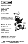
![CRRFTSMRN °] - at snowblowerguide.com](http://vs1.manualzilla.com/store/data/006202620_1-711fb90bb2c79d693479b4ac54c29ad0-150x150.png)