1
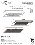
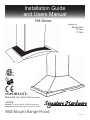
Installation Guide
and Users Manual
198 Series
Suitable for:
Standard Class
“R” Class
“E” Class
236536
IMPORTANT:
5HDGDQGVDYHWKHVHLQVWUXFWLRQV
NOTICE:
Installer:/HDYHWKLVJXLGHZLWKWKHKRPHRZQHU
Homeowner:.HHSWKLVJXLGHIRUIXWXUHUHIHUHQFH
Wall Mount Range Hood
Rev. 1016u.1a
Important Safety Notice
Read all Instructions before Installing and operating this appliance
The installation in this manual is intended for qualified installers, service technicians or persons with
similar qualified background. Installation and electrical wiring must be done by qualified profession
als and in accordance with all applicable codes and standards, including fire-rated construction.
'2127 attempt to install this appliance yourself. Injury could result from installing the unit due to
lack of appropriate electrical and technical background.
Range hood may have very sharp edges; please wear protective gloves if it is necessary to remove any
parts for installing, cleaning or servicing.
Activating any switch ON before completing installation may cause ignition or an explosion.
Due to the size and weight of this range hood, two people installation is recommended.
To reduce the risk of fire, electric shock, or injury to persons:
For general ventilating use only. '2127 use to exhaust hazardous or explosive materials and va
SRUV
The combustion air flow needed for safe operation of fuel-burning equipment may be affected by this
unit’s operation. Follow the heating equipment manufacturer’s guideline and safety standards such
as those published by the National Fire Protection Association (NFPA), and the American Society of
Heating, Refrigeration and Air Conditioning Engineers (ASHRAE), and the local code authorities.
Before servicing or cleaning unit, switch power OFF at service panel and lock service panel to pre
vent power from being switched ON accidentally.
Clean grease laden surfaces frequently. To reduce the risk of fire and to disperse air properly, make
VXUHWRYHQWDLURXWVLGH'2127 vent exhaust into spaces between walls, crawl spaces, ceiling, attics
RUJDUDJHV
Ducted fans MUST always be vented to the outdoors.
Use only metal ductwork and this unit MUST be grounded.
Sufficient air is needed for proper combustion and exhausting of gases through the duct to prevent
back drafting.
When cutting or drilling into wall or ceiling, be careful not to damage electrical wiring or other hid
GHQXWLOLWLHV
All electrical wiring must be properly installed, insulated and grounded.
Old duct work should be cleaned or replaced if necessary to avoid the possibility of a grease fire.
Check all joints on duct work to insure proper connection and all joints should be properly taped.
Use this unit only in the manner intended by the manufacturer. If you have questions, contact the
YHQGRU
To reduce the risk of a stove top grease fire:
Keep all fan, baffle, spaces, filter, grease tunnel, oil container and grease-laden surfaces clean. Grease
should not be allowed to accumulate on fan, baffle, spaces, filter, grease tunnel and oil container.
Always turn range hood ON when cooking at high heat or when cooking flaming foods.
Use high settings on cooking range only when necessary.
Never leave surface units unattended at high settings. Boil overs cause smoking and greasy spillovers
that may ignite. Heat oils slowly on low or medium settings.
Page 1
Important Safety Notice
Read all Instructions before Installing and operating this appliance
Clean ventilating fan frequently.
Always use appropriate cookware and utensils size.
Always use cookware appropriate for the size of the surface element.
To reduce the risk of injury to persons in the event of a stove top grease fire:
SMOTHER FLAMES with a close-fitting lid, cookie sheet, or metal tray, then turn OFF the burner.
BECAREFUL TO PREVENT BURNS. NEVER PICK UP A FLAMING PAN—you may be burned.
KEEP FLAMMABLE OR COMBUSTIBLE MATERIAL AWAY FROM FLAMES. If the flames DO
NOT go out immediately, EVACUATE AND CALL THE FIRE DEPARTMENT or dial your local
emergency service immediately.
DO NOT USE WATER, including wet dishcloths or towels — a violent steam explosion will result.
Use an extinguisher ONLY if:
You know you have a Class A, B, C extinguisher, and you already know how to operate it.
The fire is small and contained in the area where it is started.
The fire department is being called.
You can fight the fire with your back to an exit.
To reduce the risk of injury to persons in the event of a gas leaks:
Extinguish any open flame.
DO NOT turn on the range hood fan or any type of ventilator.
DO NOT turn on the lights or any type of appliance.
Open all doors and windows to disperse the gas. If you still smell gas, call the gas company and fire
department, or dial your local emergency service immediately.
Your safety and the safety of others is very important. We have provided many important safety mes
sages in this manual and on your appliance. Always read and obey all safety messages. All safety mes
sages will tell you what the potential hazard is, tell you how to reduce the chance of injury, and tell you
ZKDWFDQKDSSHQLIWKHLQVWUXFWLRQVDUHQRWIROORZHG
WARNING
This is the safety alert symbol. This symbol alerts you to potential hazards that can hurt you and others.
All safety messages will follow the safety alert symbol and the word “WARNING”.
The manufacturer and/or distributor/reseller declines all responsibility in the event of failure to observe the instructions given here for installation, maintenance and suitable use of the product.
The manufacturer and/or distributor/reseller further declines all responsibility for injury due to negligence and the warranty of the unit automatically expires due to improper maintenance.
The manufacturer and/or distributor/reseller will not be held responsible for any damages to personal property or real estate or any bodily injuries whether caused directly or indirectly by the range
hood.
Page 2
Table of Contents
INSTALLATION
Tools needed....................................................3
Parts supplied...................................................4
Venting requirements.......................................5
Mount heights & clearance...........................5-6
Calculating vent system length.......................6
Venting methods & ductless conversion..........7
Charcoal filters & electrical requirements.......8
Preparation......................................................9
Installation................................................10-12
Range hood operations............................13-20
USE AND CARE
Troubleshooting...........................................21
Use and care information...............................22
Specifications..............................................22
MAINTENANCE
Cleaning...............................................23
Replacing filter & light bulb.........................23
WARRANTY
Coverage & exceptions.................................24
Disclaimer & contact information..................25
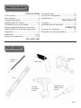
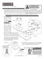
Tools needed:
Marker or
SHQFLO
0HDVXULQJ
WDSH
Utility knife
/HYHO
Powered
VFUHZGULYHU
RUGULOO
Flat-blade and
Phillips screw
GULYHUV
Page 3
5DQJH+RRG
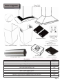
Parts supplied:
(vary with model)
)ODSSHUV
Remote Control
Aluminum Filter(s)
(Optional w/ “R” Class
Control)
Mounting Bracket
Lower standard chimney
(Not supplied with re-circulating kit)
Upper standard chimney
Flexible Duct Tube
$LUGLYHUWHU
(Optional re-circulating kit)
'HVFULSWLRQ
7RJJOH%ROWV
Duct Set
Body Hook
Chimney Mounting Bracket
This Guide and Warranty Card
5mm x 16mm Screw with Washer
4mm x 16mm Tapping Screw
4mm x 10mm Tapping Screw
Optional: Toggle Bolt with Tapping Screw for Air Diverter
Optional: Screw for Charcoal Filter
Charcoal Filter
(Optional re-circulating kit)
Quantity
2 Pcs
1 Set
2 Pcs
1 Pcs
1 Set
4 Set
6 Pcs
16 Pcs
2 Set
3 Pcs
Page 4
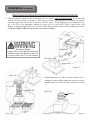
Venting Requirements
Vent system must terminate to the outside
(roof or side wall).
DO NOT terminate the vent system in an at
WLFRURWKHUHQFORVHGDUHD
DO NOT use 4” (10.2 cm) laundry-type wall
FDSV
Use metal/aluminum vent only. Rigid metal/
DOXPLQXPYHQWLVUHFRPPHQGHG
'2127XVHSODVWLFYHQW
Always keep the duct clean to ensure proper
airflow.
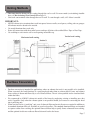
Calculate the following figures before instal
lation:
1. Distance from the floor to the ceiling.
2. Distance between the floor to the countertop/stove (recommend* 28” to 31”).
3. Distance between the countertop/stove
to the range hood.
4. Height of hood and duct cover.
Height & Clearance
Maximum* ceiling clearance
110” at 31” hood mounting
height above countertop/stove
(may vary with different
model). Chimney extensions
available for higher ceiling.
0RXQWLQJ
Bracket
Standard
8SSHU
Chimney
Extension available*
Standard
/RZHU
Chimney
Extension available*
5DQJHKRRG
For the most efficient & quiet operation:
A distance of 28” to 31” is recommended*
between stove top and the bottom of range
KRRG
It is recommended that the range hood be
vented vertically through the roof through 6”
(15.2 cm) or bigger round metal/aluminum
vent work.
The size of the vent should be uniform.
Use no more than three 90° elbows.
Make sure there is a minimum of 24” (61
cm) of straight vent between the elbows if
more than one elbow is used.
DO NOT install two elbows together.
The length of vent system and number of
elbows should be kept to a minimum to pro
vide efficient performance.
The vent system must have a damper. If
roof or wall cap has a damper, DO NOT
use damper (if supplied) on top of the range
KRRG
Use silver tape or duct tape to seal all joints
in the vent system.
Use caulking to seal exterior wall or roof
RSHQLQJDURXQGWKHFDS
* Due to different ceiling height configurations, rec
ommended height may not be applicable.
Min:28”
Max: 31”
Max*: 110”
Countertop/Stove
36” base
* Higher ceiling requires chim
ney extension. Available at your
ORFDOUHVHOOHUV
Page 5
IMPORTANT:
A minimum of 6” round (standard for this range hood) or 3-1/4 x 10” rectangular duct (purchased separately)
must be used to maintain maximum airflow efficiency.
Flexible 6” round duct provided for convenience, always use rigid type metal/aluminum ducts if available to
maximize airflow when connecting to provided duct.
Please use Duct Run Calculation below to compute the total available duct run when using elbows, transitions
DQGFDSV
ALWAYS, when possible, reduce the number or transitions and turns. If long duct run is required, increase
duct size from 6” to 7” or 8”. If a reducer is used, install a long reducer instead of a pancake reducer. Reduc
ing duct size will restrict airflow and decrease airflow, thus reduce duct size as far away from opening as pos
sible.
If turns or transitions are required: Install as far away from opening and as far apart, between 2, as possible.
Minimum mount height between stove top to hood bottom should be no less than 28-inch*.
Maximum mount height between stove top to hood bottom should be no higher than 31-inch*.
It is important to install the hood at the proper mounting height. Hoods mounted too low could result in heat
damage and fire hazard; while hoods mounted too high will be hard to reach and will loose its performance
and efficiency.
If available, also refer to stove top manufacturer’s height clearance requirements and recommended hood
mounting height above range.
* Due to different ceiling height configurations, recommended height may not be applicable.
Minimum Duct Size:
Round - 6” minimum
Rectangular - 3-1/4 x 10” minimum (requires a 6” to 3-1/4x10” adaptor, not supplied)
Calculating Vent System Length
To calculate the length of the system you need, deduct the equivalent feet for each vent piece used in the system
from the recommended maximum duct run.
Duct Run Calculation:
Recommended maximum run
6” or 3-1/4 x 10” duct
50 ft
Vent piece deduction
Each 90º elbow used
9 ft
Each 45º elbow used
5 ft
Each 6” to 3/14 x 10” transition used
7 ft
Side wall cap with damper
0 ft
5RRIFDS
0 ft
Duct Run Calcuation example:
One roof cap, two 90º elbow, and one 45º elbow used:
0ft + 9ft + 9ft + 5ft = 23ft used.
Deduct 23ft from 50ft, 27ft maximum available for
straight duct run.
Page 6
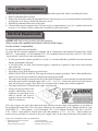
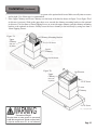
Venting Methods
This range hood is factory set for venting through the roof or wall. For non-vented (re-circulating) installa
tions, see Recirculating (Non-Vented) Kit on Page 11.
Vent work can terminate either through the roof or wall. To vent through a wall, a 90° elbow is needed.
IMPORTANT:
NEVER exhaust air or terminate duct work into spaces between walls, crawl spaces, ceiling, attics or garages.
All exhaust must be ducted to the outside.
Use metal/aluminum duct work only.
Fasten all connections with sheet metal screws and tape all joints with certified Silver Tape or Duct Tape.
Use caulking to seal exterior wall or roof opening around the cap.
Vertical roof venting
Horizontal wall venting
Option 1:
Option 2:
5RRIFDS
Side wall cap
Ductless Conversion
Ductless conversion is intended for applications where an exhaust duct work is not possible to be installed.
When converted, the hood functions as a purifying hood rather than an exhaust hood. Fumes and exhaust
from cooking is drawn and filtered by a set of charcoal filters. The air is then purified and re-circulated back
ZLWKLQWKHKRPH
We recommend to ALWAYS exhaust air outside of the home by employing existing or installing new duct
work, if possible. Only when the exhaust option is not possible should you recourse to converting the hood
into a purifying unit.
When converted to be a “purifying” unit, a set of charcoal filters and an air-diverter are required in addition to
its standard aluminum filter set. Available at your local resellers. The standard aluminum filters are intended
to capture residue from cooking, the optional charcoal filters help to purify fumes exhausted from cooking,
and the optional air-diverter redirects filtered clean air back to the house.
Page 7
Charcoal Filter Installation
NOTE: The charcoal filters are preinstalled if you purchased the range hood with re-circulating kit from us.
1. Remove aluminum filters on hood.
2. Remove the safety filter under the aluminum filter by unscrewing two screws, then position the charcoal filter
and align the screw holes, reinstall and fasten two screws.
3. Reinstall the aluminum filters back to the hood.
4. Charcoal filters must be replaced after 120 hours of use (or approximately every 2 to 3 months based on the
average of 1 to 2 hours of daily cooking time). Available at your local reseller.
Electrical Requirements
IMPORTANT: Observe all governing codes and ordinances.
(Please consult with a qualified electrician for 220-Volt 50 Hz voltage)
It is the customer’s responsibility:
To contact a qualified electrical installer.
To assure that the electrical installation is adequate and in conformance with National Electrical Code, ANSI/
NFPA 70 — latest edition*, or CSA Standards C22. 1-94, Canadian Electrical Code, Part 1 and C22. 2 No. 0-M91
- latest edition** and all local codes and ordinances.
If codes permit and a separate ground wire is used, it is recommended that a qualified electrician determine
WKDWWKHJURXQGSDWKLVDGHTXDWH
A 120-volt, 60 Hz, AC-only, fused electrical supply is required on a separate 15-amp circuit, fused on both
VLGHVRIWKHOLQH
'RQRWJURXQGWRDJDVSLSH
'RQRWKDYHDIXVHLQWKHQHXWUDORUJURXQGFLUFXLW
RISK OF ELECTRICAL SHOCK. This range hood must be properly grounded. Check with a qualified elec
trician if you are not sure whether the range hood is properly grounded.
The range hood should be connected directly to the fused disconnect (or circuit breaker) box through flexible
armored or non-metallic sheathed copper cable. A U.L. - or C.S.A. - listed strain relief must be provided at
each end of the power supply cable. Do not use extension cord or adapter plug with this appliance.
The range hood must be connected with copper wire/plug only.
Always use plug provided. If not
possible, connect three wires ac
cording to its color (black to hot,
white to neutral, and green to
:KLWH
Green
ground) to house wires and cap
Black
with wire connectors:
Wire sizes (copper wire only) and connections must conform with the rating of the appliance as specified on
the model/serial rating label. Wire sizes must conform to the requirements of the National Electrical Code
ANSI/NFPA 70 — latest edition*, or CSA Standards C22. 1-94, Canadian Electrical Code Part 1 and C22.
2 No. 0-M91 - latest edition** and all local codes and ordinances. A U.L. - or C.S.A. - listed conduit con
nector must be provided at each end of the power supply cable (at the range hood and at the junction box).
Copies of the standards listed may be obtained from:
* National Fire Protection Association
Batterymarch Park
Quincy, Massachusetts 02269
** CSA International
8501 East Pleasant Valley Road
Cleveland, Ohio 44131-5575
Page 8
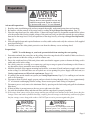
Preparation
WARNING
Excessive Weight
Require three or more person to move and
install this range hood. Spinal or other bodily injuries could occur if it is not followed.
Advanced Preparations:
1. Read the entire installation guide and users manual thoroughly, understand instructions and warnings.
2. Be familiar with the controls of the range hood by reading through Range Hood Operations, Page 13.
3. Place the range hood on a flat, stable surface. Connect the range hood to a designated standard outlet (please
refer the product label for the suitable voltage of this unit) and verify no debris has entered the vent openings,
then turn on the range hood. Verify all operations of the range hood by referring to Range Hood Operations,
Page 13.
4. Place all supplied parts and required hardware on a flat, stable surface and verify the existence of all supplied
parts listed on Page 5.
5. Carefully remove the white plastic protective coat from the chimney covers and range hood.
Preparations:
NOTE: To avoid damage to your hood, prevent debris from entering the vent opening.
1. Determine and mark the center line on the ceiling where the range hood will be installed. Make sure there is
proper clearance within the ceiling or wall for exhaust vent.
2. Due to the weight and size of this unit, please make sure that the support system or framework being used is
stable and secure in the ceiling.
3. Put a thick, protective covering over counter top, cook top or range to protect from damage or dirt. Remove
any hazardous objects around the area when installing.
4. Mark the locations of the support mounting bracket holes, vent cutout (if used) and power supply cable cutout
on the ceiling. Use drill and saber saw or keyhole saw to cut openings for power supply cable and vent (see
Venting requirementsDQGElectrical requirements, Pages 6-9).
5. If venting to the outside install vent system (see Venting Requirements, Page 3). Use caulking to seal exterior
ZDOORUURRIRSHQLQJV
6. Disconnect main electrical supply, prepare and run electrical wiring through ceiling. Leave approximately
12” of electrical cord hanging from the ceiling. Do not restore power until wiring is completed.
7. Disconnect power cord, remove the aluminum filter by pressing on the latch and gently pull the aluminum
filter down.
8. If charcoal filter is present, unscrew the two screws and remove the filter.
9. Set aside the aluminum filters and charcoal filter until the range hood is properly installed.
10. If the range hood comes with a glass canopy and has not already been mounted to the hood, loosen the four
canopy screws and washers from the hood top, carefully place the canopy on the hood top, and loosely tighten
the four canopy screws along with washers. DO NOT put excessive pressure against the glass.
WARNING
Severe Injury
Rotating fan can cause severe injury. Stay clear of
fan when motor is running.
WARNING
Severe Injury
Hood may have very shape edges. Please wear
protective gloves if it is necessary to remove
any parts for installing, cleaning or servicing.
Page 9
Installation
IInstallations
ll i
(refer
( f to Page
P
4 for
f parts):
Due to excessive weight, two or more person is recommended for this step.
WARNING
Excessive Weight
1. Locate an optimal location to place the range hood. Mark the Require three or more person to move and
leveling points for two Body Hooks (Figure 1) on the wall and install this range hood. Spinal or other bodidrill two holes with diameter not exceeding 5/8”. Insert two ly injuries could occur if it is not followed.
toggle bolts then fasten two 4mm x 16mm Tapping Screws,
reserve approximately 1/8” for the body hooks. Be sure to use appropriate anchors for your wall.
If Recirculating (Non-Vented) Kit is purchased, please skip this step and proceed to Page 11.
2. )LQGDQRSWLPDOORFD
tion for the Chimney
Mounting Bracket.
The chimney mount
Figure 1
ing bracket must be
placed directly above
DQG DOLJQ ZLWK WKH
two body hooks, see
Figure 2. Drill two
PRUH KROHV ZLWK GL
ameter not exceeding
5/8” and insert two
toggle bolts. Secure
the chimney mount
ing bracket with two
4mm x 16mm Tapping Screws as shown
in Figure 2. Be sure to use appropriate an
chors for your wall. Use four sets of 5mm
x 16mm Screw with Washer to install the
Figure 2
body hooks onto the hood. Then hang the
KRRGRQWKHZDOODQGWLJKWHQWKHVFUHZV
CAUTION: MAKE SURE the range hood
is secure before releasing!
Figure 3A
Install the Duct Set
DQG$OXPLQXPGXFW
on the body of hood.
3. Install the Duct Set using six 4mm x 16mm Tapping
Screws, then install Aluminum Duct Tube as shown in
Figure 3A and 3B. Proceed to step 6 on Page 12.
Figure 3B
Duct Set
Page 10
Installation (Continued)
If Recirculating (Non-Vented) Kit is NOT purchased, please go back to step 2 on Page 10.
4. )LQG DQ RSWLPDO ORFDWLRQ IRU WKH $LU 'LYHUWHU 7KH DLU GLYHUWHU must be placed directly above and align
with the two body hooks, see Figure 4. Drill four more holes with diameter not exceeding 5/8” and in
sert four toggle bolts. Secure the air diverter with four 4mm x 16mm Tapping Screws as shown in Fig
ure 4. Be sure to use appropriate anchors for your wall. Use four sets of 5mm x 16mm Screw with
Washer to install the body hooks onto the hood. Then hang the hood on the wall and tighten the screws.
CAUTION: MAKE SURE the range hood is secure before releasing!
WARNING
Excessive Weight
Require three or more person to move and
install this range hood. Spinal or other bodily injuries could occur if it is not followed.
Figure 4
Figure 5A
5. Install Aluminum Duct Tube as shown in Figure 5A. In
stallation of charcoal filter during this step is also recom
mended, please see Charcoal Filter Installation on Page
8.
$LU'LYHUWRU
Figure 5B
Duct Set
Safety Filter
Charcoal
)LOWHU
Page 11
Installation (Continued)
6. Connect the duct tube to the exterior exhaust system or the optional air diverter. Make sure all joints are secure
DQGDLUWLJKW8VHRIGXFWWDSHLVUHFRPPHQGHG
7. Place Upper Chimney and Lower Chimney over the body of the hood as shown in Figure 7A (or Figure 7B of
air diverter is present). Slide up the upper duct cover towards the chimney mounting bracket or the optional
air diverter. Use four 4mm x 10mm Tapping Screws to secure the upper chimney onto the chimney mounting
bracket or the optional air diverter. Finally secure the lower chimney to the hood body by using two 4mm x
10mm Tapping Screws.
Figure 7A
Chimney Mounting Bracket
8SSHU
Chimney
(has vent
ing holes)
4 x 10 Screw
/RZHU
Chimney
4 x 10 Screw
Figure 7B
8SSHU
Chimney
(has vent
ing holes)
$LU'LYHUWRU
4 x 10 Screw
/RZHU
Chimney
4 x 10 Screw
WARNING
Excessive Weight
Require three or more person to move and
install this range hood. Spinal or other bodily injuries could occur if it is not followed.
Page 12
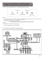
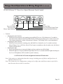
Range Hood Operations & Wiring Diagram
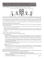
SV168/198 Series Standard Class (3 Speed Mechanical Control)
Low Speed
Power Switch
High Speed
Medium Speed
Light Switch
Turn On:
Press the speed control (Low Speed, Medium Speed, High Speed) switch to select the desired level of power.
Once button is pressed, the previous speed mode will cancel.
Press the Light Switch to power on the lights.
CAUTION: DO NOT touch the lights until switched OFF and cooled.
Turn Off:
Press the Power Switch to turn off the power.
Press the Light Switch to power off the lights
SV168/198 Series Standard Class Wiring Diagram
Page 13
Range Hood Operations & Wiring Diagram (Continued)
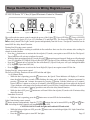
SV168/198 Series “R” Class (4 Speed Electronic Control w/ Remote)
Power-Off Delay Control
Remote Control Sensor
Power / Fan Speed Control
Speed / Timer Indicator
Light Control
This range hood is equipped with a credit card size remote control (approximately 20ft range), three built-in elec
tronic controls, a powerful centrifugal squirrel cage motor, grease filters and two bright 12V 20W halogen lights.
The three built-in electronic buttons control the power of the Lights, Power-Off Delay and Fan Speeds: Quiet (F1),
Low (F2), Medium (F3) and High (F4). The Power-Off Delay offers up to 99 minutes delay shutoff. The Light Con
trol operates independently from the Power / Fan Speed Control but can be turned OFF the delay shutoff function.
Turning Fan ON using built-in electronic controls:
Always turn fan ON before cooking to establish air flow and allow fan to run for a few minutes after cooking for
cleaner air in the kitchen.
Press the Power / Fan Speed Control button once to activate the fan at Quite (F1) mode. The Speed / Timer
Indicator will activate to indicate fan speed.
To change the fan speed, press the Power / Fan Speed Control button. Each press will cycle through Quiet
(F1), Low (F2), Medium (F3), High (F4) Speed and OFF (00). The Speed / Timer Indicator will change ac
cordingly.
Turning Fan OFF using built-in electronic controls:
The Power-Off Delay function will turn OFF both fan and lights.
1 to 99 Minute Delay
While the fan is operating, press Power-Off Delay Control button once, the Speed / Timer Indicator will
display a 15-minute timer then flash for three seconds. While flashing, the timer can be adjusted by 1
minute increments, with the default set at 15 minutes, from as short as 1 minute to as long as 99 minutes.
After the desired setting has been achieved, the Speed / Timer Indicator will return to fan speed mode and
Power-Off Delay Control button will flash until power OFF after a few seconds. Changing speed does not
affect the delay shutoff function.
While the fan is OFF, press Power-Off Delay Control button once will turn ON the fan at Quiet (F1) mode
with 15 minutes delay shut off activated.
Immediate Power-off
While the fan is operating, press the Power / Fan Speed Control button one to four times until Speed /
Timer Indicator shows “00” to turn OFF the fan immediately. NOTE: Power / Fan Speed ControlZLOO
cycle through Quiet (F1), Low (F2), Medium (F3), High (F4) Speed and OFF (00).
Light Control using built-in electronic controls:
Light Control button operates independently from the Power / Fan Speed but can be turned OFF by the Power-Off
Delay function. Activating the delay function will turn halogen lights OFF.
CAUTION: DO NOT touch the lights until switched OFF and cooled.
While the halogen lights are OFF, press the Light Control button once to turn halogen lights ON. Light
Control button will light up.
Page 14
Press the Light Control button again to turn OFF the lights.
Range Hood Operations & Wiring Diagram (Continued)
SV168/198 Series “R” Class (4 Speed Electronic Control w/ Remote)
Power-Off Delay Control
Remote Control Sensor
Power / Fan Speed Control
Speed / Timer Indicator
Light Control
7KHFUHGLWFDUGVL]HUHPRWHFRQWUROFRQWUROVWKHSRZHURIWKH/LJKWV , Power-Off Delay
, Power (ON/OFF)
and Fan Speeds: Quiet (F1), Low (F2), Medium (F3) and High (F4). The Power-Off Delay offers up to 99
minutes delay shutoff. The Light Control operates independently from the Power / Fan Speed Control but can be
turned OFF the delay shutoff function.
Turning Fan ON using remote control:
Always turn fan ON before cooking to establish air flow and allow fan to run for a few minutes after cooking for
cleaner air in the kitchen.
Press the
button once to activate the fan at Quite (F1) mode, once again to turn OFF the fan. The Speed /
Timer Indicator will activate to indicate fan speed.
While the fan is operating at Quite (F1) mode, press the button to increase fan speed. Each press will go through
Low (F2), Medium (F3), High (F4) Speed, then OFF (00). The Speed / Timer Indicator will change accordingly.
button once to activate the fan at Medium (F3) Speed. Each press will cycle throught Medium
Press the
(F3), High (F4) Speed and OFF (00).
button once to activate the fan at High (F4) Speed, once again to turn OFF the fan.
Press the
Turning Fan OFF using remote control:
The Power-Off Delay function will turn OFF both fan and lights.
1 to 99 Minute Delay
button once, the Speed / Timer Indicator will display a 15-minute
While the fan is operating, press the
timer then flash for three seconds. While flashing, the timer can be adjusted by 1 minute increments by
SUHVVLQJ
button and 1 minute decrements by pressing
button, with the default set at 15 minutes,
from as short as 1 minute to as long as 99 minutes. After the desired setting has been achieved, the Speed
/ Timer Indicator will return to fan speed mode and Power-Off Delay Control button will flash until power
OFF after a few seconds. Changing speed does not affect the delay shutoff function.
button once will turn ON the fan at Quiet (F1) mode with 15 minutes delay
While the fan is OFF, press
VKXWRIIDFWLYDWHG
Immediate Power-off
button once to turn OFF the fan immediately.
While the fan is operating, press the
Light Control using remote control:
button operates independently from the
,
,
buttons but can be turned OFF by the
DQG IXQF
tion. Activating the delay function will turn halogen lights OFF.
CAUTION: DO NOT touch the lights until switched OFF and cooled.
button once to turn halogen lights ON. Light Control but
While the halogen lights are OFF, press the
WRQZLOOOLJKWXS
Page 15
Press the
button again to turn OFF the lights.
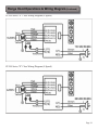
Range Hood Operations & Wiring Diagram (Continued)
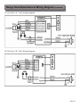
SV168 Series “R” Class Wiring Diagram
SV198 Series “R” Class Wiring Diagram
Page 16
Range Hood Operations & Wiring Diagram (Continued)
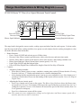
SV168/198 Series “E” Class (4 or 6 Speed Electronic Touch Control)
Power
Power-Off Delay
Decrease Value
Blower Speed Indicator
/LJKW
Increase Value
Power-Off Delay Digital Timer
Cleaning Reminder Indicator
The range hood is designed to remove smoke, cooking vapors and odors from the cook top area. For best results,
start the range hood before cooking and allow it to operate several minutes after the cooking incomplete to clear
all smoke and odors from the kitchen.
Button functions:
Power: Power ON/OFF and activate power-off delay timer.
Decrease Value: Blower (motor) speed decrease, timer value decrease, and enter timer mode.
Increase Value: Blower (motor) speed increase, timer value increase, and cleaning reminder reset.
Blower Speed Indicator: Shows current blower (motor) speed (1-4 or 1-6).
Light: Turns ON/OFF and dim halogen lights.
Power-Off Delay Digital Timer: Indicates the length of time left for delay off function.
Controls:
Automatic cleaning reminder:
When blower (motor) starts to rotate, cumulative running time reached 30 hours then the Cleaning
Reminder Indicator “C” flashes and reminds user to clean the aluminum filter.
After cleaning the filter and when the motor is not in use, press and hold Increase Value button over 3
seconds to reset the timer. Please note that turning off the system will not reset the Power-On Elapsed
Digital Timer
Adjusting the blower (motor) speed:
Press Power button once to turn on the system. The Blower Speed Indicator shows the blower (mo
tor) speed level. Decrease Value button will decrease the speed of the blower (motor) from 4 or 6 to 1
(strongest to quietest). Increase Value button will increase the speed of the blower (motor) from 1 to
4 or 6 (quietest to strongest).
Press Power button once to turn off the system.
Note: The system saves user configurations, settings such as light, timer and blower (motor) speed will remain the same the next time it is turned on.
Page 17
Range Hood Operations & Wiring Diagram (Continued)
SV168/198 Series “E” Class (4 or 6 Speed Electronic Touch Control)
Power
Power-Off Delay
Decrease Value
Blower Speed Indicator
/LJKW
Increase Value
Power-Off Delay Digital Timer
Cleaning Reminder Indicator
Controls:
Adjusting the timer function:
While the blower (motor) is not running, press and hold Decrease Value button over 3 seconds to
enter timer mode. Adjust to desired period of delay off timer by pressing Increase Value RUDecrease
Value button (minimum 1 minute to maximum 9 minutes). This setting will be saved immediately.
Activating the timer function:
While the blower (motor) is running, press and hold Power button for over 3 seconds to activate
delay off timer. Power-Off Delay Digital Timer begin to countdown, when it reaches zero, the blower
(motor) will shut down.
Adjusting the light:
Press Light button once to turn on the lights, and once again to turn off the lights.
While the lights are off, press and hold Light button for over 3 seconds to dim the lights from high to
low. Level of brightness will be stored in system’s memory.
CAUTION: DO NOT touch the lights until switched OFF and cooled.
Note: Light settings are independent from other settings (including power-off delay) and lights has to be
manually turned on or off.
Note: The system saves user configurations, settings such as light, timer and blower (motor) speed will remain the same the next time it is turned on.
Page 18
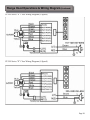
Range Hood Operations & Wiring Diagram (Continued)
SV168 Series “E” Class Wiring Diagram (4 Speed)
SV198 Series “E” Class Wiring Diagram (4 Speed)
Page 19
Range Hood Operations & Wiring Diagram (Continued)
SV168 Series “E” Class Wiring Diagram (6 Speed)
SV198 Series “E” Class Wiring Diagram (6 Speed)
Page 20
Troubleshooting
1. If the range hood or halogen light does not operate
after installation:
Check if the range hood has been plugged in, make
sure that all power has been turned back ON, fused
not blown and all electrical wiring are properly con
QHFWHG
Swap out light assembly to working ones to deter
mine whether it is caused by defective bulbs. See
Replacing the light bulbs on Page 22.
2. The range hood vibrates when the blower is on:
The range hood might not have been secured prop
erly on to the ceiling or wall. Check with your in
VWDOOHU
3. The blower or fan seems weak:
Check that the duct sized used is at least 6” or 3-1/4
x 10”. Range hood WILL NOT function efficiently
with insufficient duct size. For example: 8” duct
over 6” hole and loosely secured.
Check if duct is clogged or if damper unit (half-cir
cular flapper) is not installed correctly or opening
properly. A tight mesh on a side wall cap unit might
also cause restriction to the air flow.
4. The lights work but the blower is not spinning at all,
is stuck or is rattling.
The blower might be jammed or scraping the bot
tom due to shipping damage. Please contact us im
mediately.
Make sure the distance between the stove top and
the bottom of the hood is within* 28” and 31” in
distance. *Due to different ceiling height configurations, recommended height may not be applicable
Reduce the number of elbows and length of duct
work. Check if all joints are properly connected,
sealed, and taped.
Make sure the power is on high speed for heavy
cooking.
5. The hood is not venting out properly:
6. Purpose of the slots/holes/openings near the top of
the upper chimney:
These slots/holes/openings are used to exhaust
cleaned air with optional re-circulating kit. If you
did not install one, you do not need them.
NOTE: For all other inquiries, please contact your local reseller.
Page 21
Use and Care Information
Operations:
Read and understand all instructions and warnings in this manual before operating the appliance. Save these
LQVWUXFWLRQVIRUIXWXUHUHIHUHQFH
Always leave safety grills and filters in place. Without these components, operating blowers could catch on to
hair, fingers and loose clothing.
NEVER dispose cigarette ashes, ignitable substances, or any foreign objects into blowers.
NEVER leave cooking unattended. When frying, oil in the pan can easily overheat and catch fire. The risk of
self combustion is higher when the oil has been used several times.
NEVER cook on “open” flames under the range hood. Check deep-fryers during use: Superheated oil may be
flammable.
Cleaning:
The saturation of greasy residue in the blower and filters may cause increased inflammability. Keep unit clean
and free of grease and residue build-up at all times to prevent possible fires.
Filters must be cleaned periodically and free from accumulation of cooking residue (see cleaning instructions
on Page 18). Old and worn filters must be replaced immediately.
Do not operate blowers when filters are removed. Never disassemble parts to clean without proper instruc
tions. Disassembly is recommended to be performed by qualified personnel only. Read and understand all
instructions and warnings in this manual before proceeding.
Specifications
Body
Power Rating
General Input Power
Motor Input Power
0RWRU5HYROXWLRQ
Levels Of Speed Control
Maximum Airflow
Air Pressure
Noise Level (dB / sone)
Motor Type
Fan Type
Control Type
Filtration Type
Illumination
Venting Size
Interference Protection
Specifications*:
Stainless Steel / Tempered Glass
220V/50Hz or 120V/60Hz (USA & Canada standard)
200 W (160W + 2x20W)
160 W
800 RPM (±10%) to 1300 RPM (±10%)
3 / 4 / 6 Levels
860 CFM
150 Pa (200 Pa Maximum)
Approximately 35 / 0.7 to 67 / 6.5 (Lowest to highest Speed)
Single Chamber Ultra Quiet
Centrifugal / Sirocco
3 Spd Mechinical / 4 Spd Elec. + Remote / 4 or 6 Spd Elec. Touch
$OXPLQXP)LOWHU
20W 12V Maximum
Top, 6 inches Round
Radio Frequency Interference Protected
* Subject to change without notice, please contact your local reseller for details.
Page 22
Maintenance
SAFETY WARNING: Never put your hand into area housing the fan while the fan is operating!
For optimal operation, clean range hood and all baffle/spacer/filter/grease tunnel/oil container regularly. Regular care will
KHOSSUHVHUYHWKHDSSHDUDQFHRIWKHUDQJHKRRG
Cleaning Exterior surfaces:
Clean periodically with hot soapy water and clean cotton cloth. Do not use corrosive or abrasive detergent (e.g. Comet
Power Scruv, EZ-Off oven cleaner), or steel wool/scoring pads, which will scratch and damage the stainless steel
surface. For heavier soil use liquid degrease such as “Forumla 409” or “Fantastic” brand cleaner.
If hood looks splotchy (stainless steel hood), use a stainless steel cleaner to clean the surface of the hood. Avoid getting
FOHDQLQJVROXWLRQRQWRRULQWRWKHFRQWUROSDQHO)ROORZGLUHFWLRQVRIWKHVWDLQOHVVVWHHOFOHDQHUCAUTION: Do not
leave on too long as this may cause damage to hood finish. Use soft towel to wipe off the cleaning solution, gently
rub off any stubborn spots. Use dry soft towel to dry the hood.
After cleaning, you may use non abrasive stainless steel polish such as 3M or ZEP, to polish and buff out the stainless
luster and grain. Always scrub lightly, with clean cotton cloth, and with the grain.
'2127DOORZGHSRVLWVWRDFFXPXODWHRUUHPDLQRQWKHKRRG
DO NOT use ordinary steel wool or steel brushes. Small bits of steel may adhere to the surface and cause rusting.
DO NOT allow salt solutions, disinfectants, bleaches, or cleaning compounds to remain in contact with stainless steel
for extended periods. Many of these compounds contain chemicals, which may be harmful. Rinse with water after ex
posure and wipe dry with a clean cloth.
Cleaning Aluminum Grease Filter / Stainless Steel Filterless Grill:
IMPORTANT: Drain oil from oil containers before oil and residue overflow!
The metal filters fitted by the factory are intended to filter out residue and grease from cooking. It need not be replaced
on a regular basis but are required to be kept clean.
Filters should be cleaned after every 30 hours of use.
Remove and clean by hand or dishwasher. Spray “Formula 409” or equivalent degreasing detergent and leave to soak
if heavily soiled. Dry filters and re-install before using hood.
Replacing Filters:
Should filters wear out due to age and prolonged use, please contact your local reseller for replacement filters.
Note: Also replace damaged filter that has punctured or broken mesh, bent or broken frame.
Replacing the light bulb:
This range hood uses halogen bulb: 20W 12V.
Product ID: SV168/198-ACS-HAL20W
(please contact your local reseller for replacement)
Make sure the range hood is unplugged or turn OFF breaker.
Make sure the lights are cool to touch, turn the inner ring
counter-clockwise with a small flat head screw driver then
SRSRXWWKHSURWHFWLYHFRYHULQJ
Gently pull out the defective bulb and discard accordingly.
Install a new halogen light bulb and reverse the steps.
Turn ON breaker and range hood to test for operation.
WARNING
Hazard of Burns!
Light bulb become extremely hot when turned on.
DO NOT touch bulb until switched off and cooled.
Touching hot bulbs could cause serious burns.
Page 23
Warranty
TO OBTAIN SERVICE UNDER WARRANTY:
Yoou mu
Y
You
must
st pre
rese
sent
se
nt prooff of
of or
oriig
igin
inall purch
chas
has
asee da
date
date
te..
Plea
Pl
ease
se provi
vid
ide
de an
an or
oriig
igin
inall dattedd prooff ooff pu
p rc
rchhase
hase (sa
salles
les re
rece
ceiip
ipt / invo
invoiic
ice)) in
in or
ordder
der to
to obt
obtai
ain
in se
serv
rviice
ice un
undder
der wa
warr
rran
antty
ty.
)LYHYear Parts Warranty:
For ILYH yearV from the date of original purchase, your local reseller will provide free of charge, non-consumable replace
ment parts or components that failed due to manufacturing defects. Subject to the conditions and limitations set forth
below, your local reseller will, at its option, either repair or replace any part of its products that prove defective by reason
of improper workmanship or materials. Repaired parts or replacement products will be provided by your local reseller
on an exchange basis, and will be either new or refurbished to be functionally equivalent to new. The consumer is re
sponsible for all shipping costs. Consumable parts not covered by this warranty include but not limited to: Light bulbs,
metal, aluminum and charcoal filters.
Who is Covered:
This warranty is extended to the original purchaser for products purchased for ordinary home use.
This Warranty Will Be Voided When:
Product damaged through negligence, improper installation, accident, abuse, misuse, natural disaster, insufficient or
excessive electrical supply, abnormal mechanical or environmental conditions, or any unauthorized disassembly, repair,
modification, or failure to follow installation instructions. When product is used commercially or other than its intended
purpose. Damaged because of improper connection with equipment of other manufacturers. Repaired or modified by
anyone other than your local reseller’s authorized agents. This limited warranty also does not apply to any product on
which the original identification information has been altered, obliterated or removed, has not been handled or packaged
correctly or has been sold as second-hand.
What is Not Covered:
Consumable parts such as light bulbs, metal and charcoal filters. The natural wear of finish, and wear due to improper
maintenance, use of corrosive and abrasive cleaning products, pads, and oven cleaner products. Chips, dents or cracks
due to abuse, misuse, freight damage, or improper installation. Damage of product caused by accident, fire, floods or
act of God. The manufacturer and/or distributor/reseller is not liable for, and does not cover under warranty, any loss of
properties or any costs associated with removing, servicing, installing, or determining the source of problems with this
SURGXFW
This warranty is valid in the country of the original purchase at retail. It is non-transferable and applies only to the original
purchaser and does not extend to subsequent owners of this product. Any applicable implied warranties, including the war
ranty of merchantability, are limited in duration to a period of express warranty as provided herein beginning with the date
of original purchase at retail and, no warranties, whether express or implied, shall apply to this product thereafter.
To obtain warranty service, you may contact your local reseller from which you purchased this product. Please confirm the
terms of your local reseller’s policies prior to contacting. Typically, you must include product identification information,
including model number and serial number with a detailed description of the problem you are experiencing. You must also
include proof of the date of original retail purchase as evidence that the product is within the applicable warranty period.
The information in this document is subject to change without notice, please contact your local reseller for updated details.
Page 24
Disclaimer
Carefully inspect all items for damages before accepting delivery. note any damages on the freight bill or
express receipt. request name and signature of the carrier’s agent and keep copy to support your claim. Upon
a claim immediately. Failure to do so may result in the denial of your claim. The carrier will furnish you with
Damages caused during transit are not covered under our warranty
Please inspect contents of package(s) carefully upon receiving! W
"
#"$
"
days. NOTE: Items were thoroughly tested and carefully packed in our factory before shipping.
Products must be returned in good working condition with ALL original parts and documentation packed in
'<<=>?#
@
merchandise is exchanged for items of equal or greater amount. Exchanges or returns may not be accepted if any
packaging is missing.
Make sure to inspect the hood for damages and defects before installation. 'J
after installation and not affecting hood performance is not covered under our warranty for returns or exchanges.
Service visits not covered under warranty will carry a service charge.
Before Installation: Return for exchange or refund (please see above for acceptable returns).
After Installation: NO exchange or refund.
Contact Us
If you need any assistance, please contact Signature Hardware. Please have your order number and model of the
range hood ready. This information will help us better respond to your request.
If you need replacement parts, we recommend that you only use genuine parts. Our accessories and parts are
in durability and reliability, providing a factory match, factory-installed appearance and functionality tailored to
each individual range hood model.
Contact Signature Hardware Customer Service :
>X[\\X[X]][^
_X`{[{??>>{??
|{[{??}{??
~{[{??{?
Sunday - closed
The information in this document is = to change without notice, please contact us for updated details.
Page ]
Your Notes
Page 26
Your Notes
Page 27