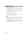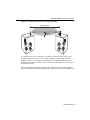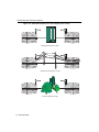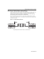
1
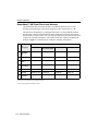
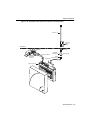
™
ENJOY THE FREEDOM OF WIRELESS NETWORKING
Outdoor Antenna
Site Preparation and Installation Guide
ENTERASYS.COM
P/N 9033348-02
Notice
Notice
Enterasys Networks reserves the right to make changes in specifications and other information contained in
this document without prior notice. The reader should in all cases consult Enterasys Networks to determine
whether any such changes have been made.
The hardware, firmware, or software described in this manual is subject to change without notice.
IN NO EVENT SHALL ENTERASYS NETWORKS BE LIABLE FOR ANY INCIDENTAL, INDIRECT,
SPECIAL, OR CONSEQUENTIAL DAMAGES WHATSOEVER (INCLUDING BUT NOT LIMITED TO
LOST PROFITS) ARISING OUT OF OR RELATED TO THIS MANUAL OR THE INFORMATION
CONTAINED IN IT, EVEN IF ENTERASYS NETWORKS HAS BEEN ADVISED OF, KNOWN, OR
SHOULD HAVE KNOWN, THE POSSIBILITY OF SUCH DAMAGES.
© January 2001 by Enterasys NetworksTM
All Rights Reserved. Printed in the United States of America.
Enterasys Networks, Inc.
35 Industrial Way
Rochester, NH 03867
Order Number: 9033348-02
Enterasys, Enterasys Networks, RoamAbout, and the RoamAbout logo are trademarks or registered
trademarks of Cabletron Systems, Inc.
Microsoft and Windows are either trademarks or registered trademarks of Microsoft Corporation.
PC Card is a trademark of PCMCIA.
All other trademarks and registered trademarks are the property of their respective holders.
Web Site: http://www.enterasys.com/wireless
i
Notice
Regulatory Information
Canada
The products included with the RoamAbout Outdoor Kit for outdoor antenna installations comply with GL-36
of Industry and Science Canada.
USA - Federal Communications Commission (FCC)
The devices included with this outdoor kit comply with Part 15 of FCC Rules. Operation of the devices in a
RoamAbout Outdoor System is subject to the following conditions:
• This device may not cause undesired interference.
• This device must accept any interference that may cause undesired operation.
Europe - EU Declaration of Conformity
Enterasys Networks declares that the RoamAbout products included in the RoamAbout Outdoor Kit conform
to the specifications listed below, following the provisions of the EMC Directive 89/336/EEC:
• ETS 300-826 General EMC requirements for Radio equipment.
• ETS 300-328 Technical requirements for Radio equipment.
User Information
To comply with the regulations listed above, you must install and use each of the RoamAbout Outdoor Kit
components (Lightning Protector, Cables and Antennas) in strict accordance with the instructions in this guide.
WARNING
This equipment may cause exposure to Radio Frequency radiation. Antennas
shall be mounted in such a manner to minimize the potential for human contact
during normal operation. To avoid the possibility of exceeding FCC radio
frequency exposure limits, do not touch the antenna during operation.
The RoamAbout outdoor antennas need to be installed by an antenna installation
professional who can determine, provide, and install the necessary support
structure and grounding system. The antenna installation professional should be
licensed or certified in accordance with local regulations.
When connecting RoamAbout devices to equipment other than the Enterasys Networks RoamAbout products
described in this guide, the antenna installation may no longer comply with the regulations as defined above.
In this case, it is the responsibility of the user to ensure that the entire antenna installation complies with local
radio regulations.
• Consult the user documentation that came with the other equipment to determine whether additional
instructions, cautions, or regulations apply.
• Verify that the antenna installer is aware of these issues and regulations.
There is no guarantee that interference to radio communications will not occur in a particular commercial
installation.
• If this device does cause interference, which can be determined by turning the host equipment off and on,
the user should refer to the host equipment documentation, or contact the local equipment supplier.
• In case the device does cause interference with an authorized radio service, the user/operator shall promptly
stop operating the device until interference is eliminated.
ii
Notice
• Enterasys Networks is not responsible for any radio or television interference caused by unauthorized
modification of the devices included with the RoamAbout Outdoor Kit, or the substitution or attachment of
connecting cables and equipment other than that specified by Enterasys Networks.
• The correction of interference caused by such unauthorized modification, substitution or attachment is the
responsibility of the user.
Electrical Hazard Warnings
1.
Antennas and cables are electrical conductors. Do not touch antennas, RoamAbout Lightning Protectors,
or antenna cables during a thunderstorm.
2. The location where you install each antenna must be at a safe distance from power lines or telephone
lines. The safe distance should be at least twice the height of the antenna mast plus the height of the
antenna.
3. The Contact between antenna components and power lines can result in serious personal injury, or
possibly death.
4. Do not install antennas or cables where there is any possibility of contact with high-voltage arc-over from
power cables or service drops to buildings.
5. During installation or removal, the antenna, supporting mast and/or tower must not be close to any power
lines.
6. The low-loss antenna cable that connects the antenna to the lightning protector must be at least 1 meter (3
feet) away from any high voltage or high current cable.
7. Check whether the antenna mast and its guy wires or wall bracket are positioned correctly and secured
properly to the roof or wall(s).
8. Check whether the grounding system for the antenna mast, the RoamAbout Access Point, and
RoamAbout Lightning Protector have been installed. The grounding system must comply with the
requirements as described in the “Verify Component Connector Polarity” section on page 3-2.
9. Always consult a qualified electrician if you are in doubt as to whether the antenna mast, Lightning
Protector, and/or RoamAbout Access Point is properly grounded.
10. The low-loss antenna cable between the antenna and the lightning protector must be grounded at all
times. If the cable is disconnected at one end for some reason (for example, to replace the lightning
protector), you must locally ground the exposed metal connector of the cable during the work.
11. Install the Danger label shipped with the antenna on a plainly visible area of the antenna support
structure.
iii
Contents
Preface
Associated Documents . . . . . . . . . . . . . . . . . . . . . . . . . . . . . . . . . . . . . . . . . . . . . . . . . . . . . . viii
Getting Help . . . . . . . . . . . . . . . . . . . . . . . . . . . . . . . . . . . . . . . . . . . . . . . . . . . . . . . . . . . . . . . ix
Document Conventions . . . . . . . . . . . . . . . . . . . . . . . . . . . . . . . . . . . . . . . . . . . . . . . . . . . . . . . x
1 Site Preparation
Choosing a Wireless Network Configuration . . . . . . . . . . . . . . . . . . . . . . . . . . . . . . . . . . . . 1-1
Determining the Antenna Locations . . . . . . . . . . . . . . . . . . . . . . . . . . . . . . . . . . . . . . . . . . . 1-2
Maximum Distances Between Antennas . . . . . . . . . . . . . . . . . . . . . . . . . . . . . . . . . . . . 1-2
RoamAbout PC Card Variations. . . . . . . . . . . . . . . . . . . . . . . . . . . . . . . . . . . . . . . . . . . 1-4
Line of Sight . . . . . . . . . . . . . . . . . . . . . . . . . . . . . . . . . . . . . . . . . . . . . . . . . . . . . . . . . . 1-4
Other Factors That Can Reduce Antenna Range . . . . . . . . . . . . . . . . . . . . . . . . . . . . . . 1-7
Other Requirements . . . . . . . . . . . . . . . . . . . . . . . . . . . . . . . . . . . . . . . . . . . . . . . . . . . . 1-8
Antenna Options . . . . . . . . . . . . . . . . . . . . . . . . . . . . . . . . . . . . . . . . . . . . . . . . . . . . . . . . . . 1-9
RoamAbout 5 dBi Vehicle-Mount Antenna . . . . . . . . . . . . . . . . . . . . . . . . . . . . . . . . . . 1-9
RoamAbout 14 dBi Directional Antenna . . . . . . . . . . . . . . . . . . . . . . . . . . . . . . . . . . . 1-10
RoamAbout 7 dBi Omni-Directional Antenna . . . . . . . . . . . . . . . . . . . . . . . . . . . . . . . 1-12
Contacting an Antenna Installation Company . . . . . . . . . . . . . . . . . . . . . . . . . . . . . . . . . . . 1-14
2 Access Point Placement and Configuration
Determining the Location of the Access Point . . . . . . . . . . . . . . . . . . . . . . . . . . . . . . . . . . . 2-1
Overview of Connecting Cables to the Access Point . . . . . . . . . . . . . . . . . . . . . . . . . . . . . . 2-2
Overview of the Access Point Configuration . . . . . . . . . . . . . . . . . . . . . . . . . . . . . . . . . . . . 2-4
v
Table of Contents
3 Antenna Installation
Installation Overview . . . . . . . . . . . . . . . . . . . . . . . . . . . . . . . . . . . . . . . . . . . . . . . . . . . . . . . 3-2
Verify Component Connector Polarity . . . . . . . . . . . . . . . . . . . . . . . . . . . . . . . . . . . . . . . . . 3-2
Grounding System . . . . . . . . . . . . . . . . . . . . . . . . . . . . . . . . . . . . . . . . . . . . . . . . . . . . . . . . . 3-4
Lightning Protector Installation . . . . . . . . . . . . . . . . . . . . . . . . . . . . . . . . . . . . . . . . . . . . . . . 3-4
Mounting the Antenna . . . . . . . . . . . . . . . . . . . . . . . . . . . . . . . . . . . . . . . . . . . . . . . . . . . . . . 3-6
Requirements for the Directional and 7 dBi Omni-Directional Antennas . . . . . . . . . . . 3-6
Antenna Polarization. . . . . . . . . . . . . . . . . . . . . . . . . . . . . . . . . . . . . . . . . . . . . . . . . . . . 3-7
Mounting the Directional Antenna . . . . . . . . . . . . . . . . . . . . . . . . . . . . . . . . . . . . . . . . . 3-8
Mounting the Omni-Directional Antenna. . . . . . . . . . . . . . . . . . . . . . . . . . . . . . . . . . . 3-10
Mounting the Vehicle-Mount Antenna. . . . . . . . . . . . . . . . . . . . . . . . . . . . . . . . . . . . . 3-12
Connecting the Antenna Cables . . . . . . . . . . . . . . . . . . . . . . . . . . . . . . . . . . . . . . . . . . . . . . 3-13
Antenna Cable Route . . . . . . . . . . . . . . . . . . . . . . . . . . . . . . . . . . . . . . . . . . . . . . . . . . 3-13
Connecting the Cables . . . . . . . . . . . . . . . . . . . . . . . . . . . . . . . . . . . . . . . . . . . . . . . . . 3-14
Optimizing RoamAbout Outdoor Antenna Placement . . . . . . . . . . . . . . . . . . . . . . . . . . . . 3-15
Routine Maintenance . . . . . . . . . . . . . . . . . . . . . . . . . . . . . . . . . . . . . . . . . . . . . . . . . . . . . . 3-16
A Specifications
RoamAbout 14 dBi Directional Antenna. . . . . . . . . . . . . . . . . . . . . . . . . . . . . . . . . . . . . . . . A-1
RoamAbout 7 dBi Omni-Directional Antenna . . . . . . . . . . . . . . . . . . . . . . . . . . . . . . . . . . . A-3
Vehicle-Mount Antenna. . . . . . . . . . . . . . . . . . . . . . . . . . . . . . . . . . . . . . . . . . . . . . . . . . . . . A-4
RoamAbout Pigtail Connection . . . . . . . . . . . . . . . . . . . . . . . . . . . . . . . . . . . . . . . . . . . . . . . A-5
Low-Loss Antenna Cable. . . . . . . . . . . . . . . . . . . . . . . . . . . . . . . . . . . . . . . . . . . . . . . . . . . . A-6
RoamAbout Lightning Protector . . . . . . . . . . . . . . . . . . . . . . . . . . . . . . . . . . . . . . . . . . . . . . A-8
vi
Preface
This guide describes the requirements that are needed for the successful installation of the
RoamAbout outdoor antennas used in a RoamAbout wireless network. A RoamAbout
wireless network consists of RoamAbout wireless products, such as the RoamAbout PC
Card and RoamAbout Access Point, and other wireless products that use an 802.11 Direct
Sequence (DS) compliant radio.
ELECTRICAL HAZARD: Only qualified personnel should
perform installation procedures for outdoor antennas.
The RoamAbout outdoor antennas need to be installed by an antenna installation
professional who can determine, provide, and install the necessary support structure and
grounding system. The antenna installation professional should be licensed or certified in
accordance with local regulations.
Intended Audience
Chapter 1 contains the information needed by a sales engineer or site evaluator to determine
the type of outdoor equipment needed to satisfy the customer outdoor wireless
requirements.
Chapter 2 is for an antenna installation professional and network manager to determine
where to place the RoamAbout Access Point and Lightning Protector. This chapter also
provides an overview of cabling and configuring the Access Point.
Chapter 3 contains the information needed for an antenna installation professional to setup,
install, and test the RoamAbout outdoor antennas and cables.
vii
Preface
Associated Documents
The documentation, drivers, and utilities can also be downloaded from the RoamAbout
Wireless web site.
Check the RoamAbout Wireless web site regularly for product upgrades.
http://www.enterasys.com/wireless
Component
Information Location
RoamAbout Access Point
RoamAbout Access Point 2000 Hardware
Installation Guide
RoamAbout Access Point 2000 Hardware
Installation Quick Start
RoamAbout Access Point
Manager
RoamAbout 802.11 Wireless Networking
Guide
RoamAbout 802.11 DS PC Card
RoamAbout 802.11 PC Card Drivers and
Utilities CD-ROM Kit
RoamAbout 802.11 Drivers
RoamAbout 802.11 PC Card Drivers and
Utilities CD-ROM Kit
RoamAbout 802.11 PC Card Drivers and
Utilities Setup and Installation Guide
viii
RoamAbout Client Utility
RoamAbout 802.11 PC Card Drivers and
Utilities CD-ROM Kit
RoamAbout Work Station Update
RoamAbout 802.11 PC Card Drivers and
Utilities CD-ROM Kit
RoamAbout ISA Adapter Card
RoamAbout ISA Adapter Installation
RoamAbout PCI Adapter Card
RoamAbout PCI Adapter Installation
RoamAbout Outdoor Solution
RoamAbout Outdoor Antenna Site
Preparation and Installation Guide
Preface
Getting Help
For additional support related to this device or document, contact Enterasys Networks
using one of the following methods:
World Wide Web: http://www.enterasys.com/wireless
Phone:
North America: (603) 332-9400
Europe: 353 61 701 910
Asia: +800 8827-2878
Internet mail:
[email protected]
To send comments or suggestions concerning this document, contact the Enterasys
Networks Technical Writing Department via the following e-mail
address: [email protected]
Make sure you include the document Part Number in the e-mail message.
Before calling Enterasys Networks, please have the following information ready:
•
Your Enterasys Networks service contract number
•
A description of the problem
•
A description of any action(s) already taken to resolve the problem
•
The serial and revision numbers of all involved Enterasys Networks products in the
network
•
A description of your network environment (for example, layout, cable type)
•
Network load and frame size at the time of trouble (if known)
•
The device history (for example, have you returned the device before, is this a
recurring problem)
•
Any previous Return Material Authorization (RMA) numbers
ix
Preface
Document Conventions
The following icons are used in this document:
Icon
Meaning
ELECTRICAL HAZARD: Warns against an action that
could result in personal injury or death.
WARNING
WARNING: Warns against an action that could result in
personal injury or death.
CAUTION: Contains information essential to avoid
damage to the equipment.
NOTE
x
NOTE: Calls the reader’s attention to any item of
information that may be of special importance.
Chapter 1
Site Preparation
This chapter describes the site requirements that are needed for the successful installation
of the RoamAbout outdoor antennas. It is intended for sales engineers or site evaluators.
If after reviewing this document you require additional technical information or support
prior to ordering product, contact your authorized Enterasys Networks Sales
Representative or see the RoamAbout web site:
http://www.enterasys.com/wireless
Choosing a Wireless Network Configuration
The antennas you need depend on the wireless network configuration:
•
LAN-to-LAN, Point-to-Point
This is a wireless link between two Access Points that connects two separate wired
LANs. Typically, two directional antennas are used.
•
LAN-to-LAN, Point-to-Multipoint
In a point-to-multipoint network, up to seven Access Points provide wireless links to
connect up to seven LANs. One Access Point is designated as the central (multipoint)
Access Point. The other Access Points are called endpoints and only communicate
with the Central Access Point. Typically, the Central Access Point connects to an
omni-directional antenna. The endpoint Access Points connect to a directional
antenna.
•
Wireless Infrastructure
This is an inside/outside wireless network where one or more Access Points are used
to connect clients to a wired LAN. Typically, the Access Points use an
omni-directional antenna or a sectored antenna, and the clients use a vehicle-mount
antenna. An example of this type of network is a warehouse where drivers in forklifts
need to access the LAN.
Site Preparation 1-1
Determining the Antenna Locations
Determining the Antenna Locations
The locations where the antennas can be placed relative to one another and the distance
between them are based on the following factors:
•
Type of antennas. The RoamAbout antennas are described in the “Antenna Options”
section on page 1-9.
•
Length of cable from the antenna to the Access Point.
•
Data rate required.
•
Obstructions in the signal path.
•
Type of RoamAbout PC Card.
•
In a LAN-to-LAN network, the distance between the buildings.
•
In a wireless infrastructure network, the area around the antenna where clients need to
communicate with the Access Point.
Typically, the RoamAbout directional and omni-directional antennas are installed on
rooftops. The directional antenna can also be installed to the side of a building. The
vehicle-mount antenna is mounted to a vehicle and connected to the client with a 2.5 meter
(8 foot) cable. The following sections describe the factors that affect the range of the
antennas.
Maximum Distances Between Antennas
The following tables list the maximum distance between antennas at a given data rate. The
distance in tables are based on the following:
•
15 meter (50 foot) low-loss antenna cable from the antenna to the Access Point.
•
Type of PC Card (standard or Hi-Gain matched). See the “RoamAbout PC Card
Variations” section on page 1-4.
•
No obstructions in the line of sight. See Table 1-1 and Table 1-2. The Line of Sight
Clearance column indicates the radius of the radio beam. Obstructions in the line of
sight reduces the total distance, as described in the “Line of Sight” section on page
1-4.
1-2 Site Preparation
Determining the Antenna Locations
Table 1-1: Distances and Line of Sight Clearance (FCC)
Data
Rate
Mbit/s
14 dBi Yagi to 14 dBi Yagi
14 dBi Yagi to 7 dBi Omni
7 dBi Omni to
Vehicle-Mount
Distance
Line of
Sight
Clearance
Distance
Line of
Sight
Clearance
Distance
Line of
Sight
Clearance
11
5.6 km
(3.5 mi)
9.8 m
(33 ft)
2.5 km
(1.5 mi)
6.3 m
(21 ft)
0.8 km
(0.5 mi)
3.4 m
(11.2 ft)
5.5
7.9 km
(4.9 mi)
12.1 m
(40 ft)
3.5 km
(2.1 mi)
7.5 m
(25 ft)
1.1 km
(0.7 mi)
4.1 m
(13.5 ft)
2
11.2 km
(6.9 mi)
15.4 m
(51 ft)
5 km
(3.1 mi)
9.1 m
(30 ft)
2 km
(1.2 mi)
5.6 m
(18.4 ft)
1
15.8 km
(9.8 mi)
20.3 m
(67 ft)
7.1 km
(4.4 mi)
11.3 m
(37 ft)
2.5 km
(1.5 mi)
6.3 m
(21 ft)
Table 1-2: Distances and Line of Sight Clearance ETSI
Data
Rate
Mbit/s
14 dBi Yagi to 14 dBi Yagi1
14 dBi Yagi1 to 7 dBi Omni
7 dBi Omni to
Vehicle-Mount
Distance
Line of
Sight
Clearance
Distance
Line of
Sight
Clearance
Distance
Line of
Sight
Clearance
11
2.5 km
(1.5 mi)
6.3 m
(21 ft)
1.1 km
(0.7 mi)
4.1 m
(14 ft)
0.8 km
(0.5 mi)
3.4 m
(11.2 ft)
5.5
3.5 km
(2.1 mi)
7.5 m
(25 ft)
1.6 km
(1 mi)
4.9 m
(16 ft)
1.1 km
(0.7 mi)
4.1 m
(13.5 ft)
2
5 km
(3.1 mi)
9.1 m
(30 ft)
2.2 km
(1.4 mi)
5.9 m
(20 ft)
2 km
(1.2 mi)
5.6 m
(18.4 ft)
1
7.1 km
(4.4 mi)
11.3 m
(37 ft)
3.2 km
(2 mi)
7.1 m
(24 ft)
2.5 km
(1.5 mi)
6.3 m
(21 ft)
1 The
Yagi antenna must be connected to an Access Point configured with the Hi-Gain matched RoamAbout PC Card.
Site Preparation 1-3
Determining the Antenna Locations
RoamAbout PC Card Variations
There are two variations of the RoamAbout PC Card: standard and Hi-Gain matched.
The Hi-Gain matched variation of the RoamAbout PC Card is only used when connecting
to a directional antenna in countries that adhere to the European Telecommunications
Standards Institute (ETSI) standards.
All other countries and other configurations use the same standard RoamAbout PC Card.
For example, all countries use the standard RoamAbout PC Card in these configurations:
•
PC Card is not connected to an antenna.
•
PC Card is connected to a 7 dBi omni-directional antenna.
•
PC Card is connected to a vehicle-mount antenna.
Countries that adhere to the Federal Communications Commission (FCC) standards use the
standard RoamAbout PC Card in all configurations.
Line of Sight
The shape of the radio beam, defined as the Fresnel Zone, is widest in the middle. The
Fresnel Zone is shown as the gray area between the antennas in Figure 1-1. The exact shape
and width of the Fresnel Zone is determined by the distance between the antenna and
frequency of the radio signal.
The radius of the radio beam, shown as the lower half of the Fresnel Zone, is the distance
from the center of the beam outward in any direction. The length of the radius is shown in
Table 1-1 and Table 1-2 as the line of sight clearance. The length of the radius is not based
on the data rate and the type of antenna.
1-4 Site Preparation
Determining the Antenna Locations
Figure 1-1: Fresnel Zone and Line of Sight Clearance
Total Distance
Radius
If a significant part of the Fresnel Zone is obstructed, a portion of radio energy is lost,
resulting in reduced performance. For optimal performance, ensure that the antenna
products you choose, in combination with the height of the antenna installation above
ground, provide sufficient clearance to allow your antenna installation to cover the distance
between the two sites.
Obstacles within the line of sight can significantly reduce the distance and performance.
Obstructions include neighboring buildings, trees, and power lines as shown in Figure 1-2.
Site Preparation 1-5
Determining the Antenna Locations
Figure 1-2: Potential Obstacles to Line of Sight (not to scale)
Building blocking line of sight
Power lines blocking line of sight
100_02
Trees blocking line of sight
1-6 Site Preparation
Determining the Antenna Locations
Other Factors That Can Reduce Antenna Range
Large reflecting surfaces that are parallel or partly perpendicular to the radio signal cause
reflections of the radio signal (see Figure 1-3). Examples of reflecting surfaces are
buildings with low-emissivity (low-e) glass, crowded parking lots, water, moist earth,
moist vegetation, and above-ground power or telephone lines.
Because surrounding objects, such as trees, power lines, and other antennas, seriously
reduce efficiency of the antenna, it is very important to mount the antenna as high and clear
of obstacles as possible.
Figure 1-3: Large Reflecting Surfaces
100_03
Large storage tanks which are common in industrial areas
Site Preparation 1-7
Determining the Antenna Locations
Other Requirements
The following describes other requirements to meet before installing the RoamAbout
outdoor antennas.
•
Lightning Protection
A lightning rod must be placed close to the antenna mast or wall bracket. This is
required to protect the antenna from direct lightning strikes.
•
Grounding System
Direct earth grounding of the antenna and the Lightning Protector is necessary to
protect the installation from lightning and the build-up of static electricity. The
wireless device and the Lightning Protector must be connected to the same ground.
The antenna and the mounting structure require a separate earth ground connection.
Check with a certified antenna installer to make sure the antenna is properly grounded.
Ensure that the cable between the antenna and Lightning Protector is at least 0.9 meters
(3 feet) away from high-voltage or high-current cable.
•
Antenna Height
If you are mounting the antenna on a roof, it must be at least 1.5 meters (5 feet) above
the roof line.
If you are mounting the directional antenna to a wall of a building, it must be high
enough to achieve a clear line of sight. Mounting an omni-directional antenna to the
side of a building can cause signal reflection and reduce distance.
The installer is responsible for local building codes.
NOTE
•
Access Point placement
The Access Point should be located indoors and connected to the outdoor antenna with
a standard 6 meter (20 foot), 15 meter (50 foot), or 22 meter (75 foot) low-loss cable.
A longer cable could cause additional signal loss and decrease the distance between
antennas.
1-8 Site Preparation
Antenna Options
Antenna Options
The following sections describe the RoamAbout outdoor antennas. Appendix A contains
the specifications for each antenna.
RoamAbout 5 dBi Vehicle-Mount Antenna
The RoamAbout vehicle-mount antenna (Figure 1-4) is a broadband antenna for the 2.4
GHz frequency band featuring an omni-directional pattern with a nominal gain of 5 dBi.
The vehicle-mount antenna can be mounted on vehicles, such as fork-lift trucks, that need
continuous access to network data whether inside or outside of the building.
W
iF
i
H
i-
e pt
at
R da
h A
ig
H ed
S ch
D at
1 M
2. it
80 ab
ig
G
er
Figure 1-4: Vehicle-Mount Antenna
WIR
ENJ
Site Preparation 1-9
ELE
OY
SS
THE
LAN
S
FRE
EDO
M
OF
WIR
ELE
SS
NET
WO
RKI
NG
Antenna Options
RoamAbout 14 dBi Directional Antenna
The directional antenna is a totally enclosed 16-element Yagi designed for point-to-point
communications. The antenna is normally mounted on a mast and vertically polarized. The
following table shows the components and part numbers in the RoamAbout directional
antenna kit. The numbers in the first column correspond to the numbers in Figure 1-5,
which shows an example of a cabling configuration.
#
Packaged
Kit/
Component
Component Part Numbers by Domain
FCC
ETSI*
France
Asia Pacific
FCC
Asia Pacific
ETSI*
OUTDOOR
ANTENNA
KIT
CSIED-AB
CSIED-AB
CSIED-AF
CSIEDAP-FCC
CSIEDAP-ETSI
1
Antenna
CSIESAB-Y14
CSIESAB-Y14
CSIESAB-Y14
CSIESAB-Y14
CSIESAB-Y14
2
50-foot
Cable
CSIESAB-C50
CSIESAB-C50
CSIESAB-C50
CSIESAB-C50
CSIESAB-C50
3
Pigtail
Connection
CSIESAB-PT50
CSIESAB-PT50
CSIESAB-PT50
CSIESAB-PT50
CSIESAB-PT50
4
Access
Point
CSIWS-AB
CSIWS-AB
CSIWS-AB
CSIWS-AB
CSIWS-AB
5
PC Card
CSIBDAA-128**
CSILD-AB
CSILD-AF
CSIBD-AB
CSIBD-AB
6
Lightning
Protector
CSIESAB-LP
CSIESAB-LP
CSIESAB-LP
CSIESAB-LP
CSIESAB-LP
*European Telecommunications Standards Institute.
**128-bit encryption RoamAbout PC Card.
1-10 Site Preparation
Antenna Options
Figure 1-5: Example Outdoor Yagi Antenna Configuration
Antenna (1)
Antenna
Cable
OUTDOOR
Remote Power
Adapter
INDOOR
Low-Loss
Cable (2)
Lightning
Protector (6)
To Power Outlet
Insert Ethernet
Cable from
Network
Ground Strap
PC Card (5)
Pigtail
Connection (3)
Access Point (4)
S1
S2
MA
AD C
D
SN
ww
w.c
a
ble
tro
n.c
om
/w
TU
ire
V
les
s
2
1
Site Preparation 1-11
Antenna Options
RoamAbout 7 dBi Omni-Directional Antenna
The RoamAbout omni-directional antenna is a broadband antenna for the 2.4 GHz
frequency band featuring an omni-directional pattern with a nominal gain of 7 dBi.
This antenna is encapsulated in a weatherproof protective covering. With the hardware
provided, this vertically-polarized antenna can be mounted on an antenna mast with an
outside diameter of up to 51mm (2 in). The following table shows the antenna and related
components with their part numbers. The numbers in the first column correspond to the
numbers in Figure 1-6, which shows an example of a cabling configuration.
#
Packaged
Kit/
Component
Component Part Numbers by Domain
FCC
ETSI* and
Asia Pacific ETSI*
France
Asia Pacific FCC
OUTDOOR
ANTENNA
KIT
CSIED-AA-M07
CSIED-AB-M07
CSIED-AF-M07
CSIED-APFCCM7
1
Antenna
CSIES-AB-M07
CSIES-AB-M07
CSIES-AB-M07
CSIES-AB-M07
2
50-foot
Cable
CSIES-AB-C50
CSIES-AB-C50
CSIES-AB-C50
CSIES-AB-C50
3
Pigtail
Connection
CSIES-AB-PT50
CSIES-AB-PT50
CSIES-AB-PT50
CSIES-AB-PT50
4
Access Point
CSIWS-AB
CSIWS-AB
CSIWS-AB
CSIWS-AB
5
PC Card
CSIBD-AA-128**
CSIBD-AB
CSIBD-AF
CSIBD-AB
6
Lightning
Protector
CSIES-AB-LP
CSIES-AB-LP
CSIES-AB-LP
CSIES-AB-LP
* European Telecommunications Standards Institute
**128-bit encryption RoamAbout PC Card.
1-12 Site Preparation
Antenna Options
Figure 1-6: Example Omni-Directional Antenna Configuration
Antenna (1)
Mounting
Pole or
Mast
OUTDOOR
Remote Power
Adapter
INDOOR
Low-Loss
Cable (2)
Lightning
Protector (6)
To Power Outlet
Insert Ethernet
Cable from
Network
Ground Strap
PC Card (5)
Pigtail
Connection (3)
Access Point (4)
S1
S2
MA
AD C
D
SN
ww
w.c
a
ble
tro
n.c
om
/wir
TU
V
ele
ss
2
1
Site Preparation 1-13
Contacting an Antenna Installation Company
Contacting an Antenna Installation Company
Have an antenna installation professional install the outdoor antennas. The antenna installer
provides the expertise to properly install, secure, and ground your antenna. The following
describes tasks that the installer may need to perform.
NOTE
The antenna installation professional should be licensed or certified in
accordance with local regulations.
Lightning Protection
√
Determine the mounting location for the lightning rod (positioned near the antenna).
√
Ensure an earth ground location for the antenna structure and lightning protector.
Mounting Requirements
√
Determine the type of mounting that is required (tripod, wall mount, etc.)
√
Determine the guy wires needed. Typically, three guy wires are needed for each 3
meter (10 foot) section of the mast; for example, 6 meters (20 feet) of mast requires
six guy wires.
Line of Sight
√
Determine the mounting location for the antenna.
√
Ensure that the back of the antenna is clear.
√
Ensure that remote and local antennas can see each other.
√
Ensure that no obstacles are in the direct path or within the defined zone of the two
sites.
√
Consider whether any RF interference is present.
1-14 Site Preparation
Contacting an Antenna Installation Company
Installation Requirements
√
Determine the best location for the Access Point.
√
Determine the length of cable required from the antenna to the Access Point.
√
Ensure the location has an accessible Ethernet connection.
√
Determine the distance between buildings.
You may need to provide the following distances when contacting the antenna installation
company:
Distance between the antennas
(building-to-building network):
Coverage area required (wireless
infrastructure network configuration):
Height of building A:
Height of building B:
All possible obstacles which can
interfere with the defined radius.
WARNING
WARNING: Site prerequisites should be verified by a person familiar with
national codes, local electrical codes, and with other regulations governing
this type of installation. Enterasys Networks, its channel partners, resellers,
and distributors assume no liability for personal injury, property damage, or
violation of government regulations that may arise from failing to comply
with the instructions in this guide.
Site Preparation 1-15
Chapter 2
Access Point Placement and
Configuration
This chapter is for the antenna installer and network manager to determine where to place
the RoamAbout Access Point and Lightning Protector. This chapter also provides an
overview of cabling and configuring the Access Point.
Determining the Location of the Access Point
The RoamAbout Access Point connects to a Lightning Protector with a 50 centimeter (19.5
inch) cable. The Lightning Protector connects to the outdoor antenna with a standard 6
meter (20 foot), 15 meter (50 foot), or 22 meter (75 foot) low-loss cable. A longer cable can
decrease the distance achievable between antennas. The ideal location to install your
RoamAbout Access Point and Lightning Protector must satisfy the following requirements:
•
The location must be indoors to protect the Access Point from extreme weather
conditions, excessive heat and humidity, and to keep the unit free from vibration and
dust.
•
The Lightning Protector and antenna mast must be connected to the same grounding
system as the AC wall outlet ground (see “Verify Component Connector Polarity”
section on page 3-2).
•
The location must provide a connection to the network backbone via an Ethernet LAN
cable going to a hub, bridge, or directly into a patch panel.
•
The location must be close to where the low-loss antenna cable will enter the building.
The low-loss cable connecting the antenna to the Lightning Protector should not
exceed a 22 meter (75 foot) length.
•
The Lightning Protector must be accessible so that the Gas Discharge Tube can be
replaced, as described in the “Routine Maintenance” section on page 3-16.
Access Point Placement and Configuration 2-1
Overview of Connecting Cables to the Access Point
Overview of Connecting Cables to the Access Point
Before cabling the Access Point, you should install the Access Point to a wall or ceiling.
For detailed hardware installation procedures, see the RoamAbout Access Point 2000
Hardware Installation Guide. Figure 2-1 provides you with an illustration of the steps
listed in the following procedure.
1.
Insert the PC Card into the Access Point. Refer to the RoamAbout 802.11 PC Card
Installation Guide for Regulatory and Installation information before installing the PC
Card.
Figure 2-1: Access Point 2000 Installation Overview
5
8
To Power Outlet
6
Insert Ethernet
Cable from
Network
7
3
2
To Lightning
Protector
1
MAC
Address
4
S1
S2
MA
AD C
D
SN
ww
w.c
a
ble
tro
n.c
om
/wir
TU
V
ele
ss
2
2-2 Access Point Placement and Configuration
1
Overview of Connecting Cables to the Access Point
2.
Remove the plastic cap from the PC Card and connect the pigtail cable. After the
Lightning Protector has been installed and grounded, connect the other end of the
pigtail cable to the Lightning Protector.
3.
If using the remote power option, connect the Ethernet cable from the Access Point to
the Access Point connector on the remote power adapter.
NOTE
The Access Point’s MAC address on the front label. You need this address
when configuring the Access Point from the Access Point Manager program.
4.
If using the remote power option, connect the power adapter to the Power connector
on the remote power adapter. Do NOT connect the power adapter to the source at this
time.
5.
If using the remote power option, connect the Ethernet cable from the site network to
the Ethernet connector on the remote power adapter.
NOTE
If not using the remote power option, connect the network and power cables
directly to the Access Point.
6.
Optionally, snap the cover on. Some installation configurations do not require the
plastic cover.
7.
Connect the power adapter to the power source.
Access Point Placement and Configuration 2-3
Overview of the Access Point Configuration
Overview of the Access Point Configuration
The following provides an overview of configuring the Access Point with the Access Point
Manager. For detailed procedures, see the RoamAbout 802.11 Wireless Networking Guide
or click the Help button in the Access Point Manager. Before you begin, you need the
following:
•
A valid unused IP address for each Access Point from the network administrator.
•
The wireless MAC address of both Access Points. The wireless MAC address is NOT
the same as the wired MAC address printed on the Access Point label. Perform one of
the following to see the wireless MAC address:
— If both Access Points are currently managed by the AP Manager, select each
Access Point from the Managed List field and click the Hardware button.
— Using the Access Point console port at each Access Point, choose Show Current
Settings from the RoamAbout Access Point Installation Menu.
— Check the back of the PC Card used in the Access Points. The MAC address of
the PC Card is the Access Point’s wireless MAC address.
1.
Install the Access Point Manager on a Windows 95, 98, 2000, Millennium, or NT
(V4.0 or later), computer that is located on the same wired network as the Access
Point.
2.
Open the Access Point Manager (Start button, Programs→RoamAbout→
RoamAbout Access Point Manager).
3.
Click the Setup/Add New Access Point button (Figure 2-2). When prompted, click
Yes to load an IP address.
4.
Enter the Access Point’s wired MAC address.
5.
Enter the unused IP address. Click OK. You may need to wait a few minutes for the
address to load.
6.
In the Identification dialog box, enter a unique system name that identifies the Access
Point then click OK.
7.
In the Station Name field, enter a unique name for the Access Point. The station name
is displayed when running the Link test. Click OK.
8.
In the Wireless Parameters dialog box, select a channel for the Access Points. All
Access Points in a LAN-to-LAN configuration must use the same channel.
9.
Click the Advanced button.
2-4 Access Point Placement and Configuration
Overview of the Access Point Configuration
Figure 2-2: RoamAbout Access Point Manager
10. If this is a Point-to-Multipoint configuration and the selected Access Point is the
designated central Access Point, perform the following:
a) Select LAN-to-LAN Multipoint in the Bridge Mode field.
NOTE
You must purchase a license with a valid activation key to enable Multipoint
Bridge Mode. Contact your Enterasys Networks Representative.
b) Enter the Multipoint activation key.
c) Click on the LAN-to-LAN Multipoint Properties button in the Wireless
Parameters dialog box.
Access Point Placement and Configuration 2-5
Overview of the Access Point Configuration
d) Enter the wireless MAC addresses of the other Access Points. Click OK when
done. Then click OK in the Wireless Parameters dialog box.
11. For all other Access Points, select LAN-to-LAN Endpoint in the Bridge Mode field.
In the Wireless MAC Address field, enter the wireless MAC address of the remote
Access Point (Point-to-Point) or central Access Point (Point-to-Multipoint).When
done, click OK in the Wireless Parameters dialog box.
12. In the main window, click the Reset button. Choose to Reset with Current Settings.
Allow approximately one minute for the Access Point to reset and run its self-test.
2-6 Access Point Placement and Configuration
Chapter 3
Antenna Installation
This chapter provides the information necessary for a professional antenna installer to
install the RoamAbout antennas.
WARNING
WARNING: Antennas should only be installed by a qualified antenna
installer. The antenna installation professional should be licensed or
certified in accordance with local regulations.
Do not install the antenna in wet, windy, icy, or otherwise unsafe weather
conditions.
The RoamAbout outdoor antenna kits do NOT provide the following items, which may be
necessary to install the antenna:
•
Mast or other antenna support structure
•
Guy wires
•
All cables or other hardware necessary for a complete grounding system
•
Waterproof tape
NOTE
It is the responsibility of the end-user to ensure that an outdoor antenna
installation complies with local radio regulations.
Antenna Installation 3-1
Installation Overview
Installation Overview
The installation process is summarized in the following steps. The following sections in this
chapter provide additional details.
1.
Make sure the Access Points are mounted and configured as specified in Chapter 2.
2.
Check the cable connectors to verify that they are the correct polarity for your
installation.
3.
Plan and implement a grounding system that meets local electrical codes and safety
standards.
4.
Install the RoamAbout Lightning Protector.
5.
Provide and install an antenna support structure as necessary. Make sure that the
support structure is connected to the grounding system.
6.
Connect the exposed metal connectors of the low-loss antenna cable to the grounding
system.
7.
Mount the antenna to the support structure.
8.
Connect the antenna cables.
9.
Route and connect the low-loss antenna cable to the RoamAbout Lightning Protector.
10. Connect the cable assembly from the RoamAbout PC Card in the Access Point to the
Lightning Protector.
11. Run the Access Point Manager Link Test program to aim the antenna and verify
optimal placement.
12. After verifying that the communications link is fully operational, secure all cables and
use weatherproofing tape to seal all outdoor connectors.
Verify Component Connector Polarity
Before you start the antenna installation, refer to Figure 3-1 to verify that the polarity of
each connector is correct for your installation. The components supplied with your outdoor
antenna kit are configured with either Standard-N connectors or Reverse Polarity-N
connectors, subject to the country where the kit was purchased.
3-2 Antenna Installation
Verify Component Connector Polarity
Figure 3-1: Selecting the Correct N-Type Connector
1
Pigtail
Connection
(A)
2
Lightning
Protector
(B)
ETSI Countries: France, Spain, and
Japan.
Asia Pacific FCC and ETSI.
A
Antenna
Cable
(D)
Low-Loss
Cable
(C)
FCC Countries.
Standard-N Male
Reverse Polarity-N Female
Standard-N Female
Reverse Polarity-N Male
1 - PC Card connector
1 - PC Card connector
2 - Standard-N Male
2 - Reverse Polarity-N Female
B
Standard-N Female on both ends
Reverse Polarity-N Male on both ends
C
Standard-N Male on both ends
Reverse Polarity-N Female on both ends
D
Standard-N Female
Reverse Polarity-N Male
The term Male or Female does not refer to the connector thread, but to its center pin.
•
Male connectors have a solid
center pin
•
Female connectors have a
hollow center pin
Male Female
If you purchase individual components, make sure you specify the correct N-Type
connectors to match the configuration that applies to your country.
Antenna Installation 3-3
Grounding System
Grounding System
Direct earth grounding of the antenna and the Lightning Protector is necessary to protect
the installation from lightning and the build-up of static electricity.
The grounding system must satisfy the following requirements:
•
The antenna mast, RoamAbout Access Point, and RoamAbout Lightning Protector
must be connected to the same ground.
•
The antenna and the mounting structure require a separate earth ground connection.
Check with a certified antenna installer to make sure the antenna is properly grounded.
•
Ensure that the cable between the antenna and Lightning Protector is at least 0.9 meters
(3 feet) away from high-voltage or high-current cable.
•
A good electrical connection must be made to one or more ground rods, using at least
a 10AWG ground wire and noncorrosive hardware.
•
The grounding system must comply with electrical codes and safety standards that
apply in your locality.
Have a qualified electrician verify that your RoamAbout outdoor installation is properly
grounded.
CAUTION: A properly installed safety grounding system is necessary to
protect your RoamAbout outdoor installation from lightning strikes and
static electricity build-up.
Lightning Protector Installation
Lightning protection is designed to protect people, property and equipment by providing a
path to the ground whenever lightning strikes your antenna installation. The RoamAbout
Lightning Protector is an indispensable part of such a grounding system to protect your
electronic equipment from transients and/or electrostatic discharges at the antenna.
For optimal protection, the location of the RoamAbout Lightning Protector:
•
Must be as close as possible to the point where the antenna cable enters the building.
•
Allow for easy access to the Lightning Protector so that the Gas Discharge Tube
(GDT) in the Lightning Protector can be replaced as necessary.
•
Provide a connection to the same grounding system as the RoamAbout Access Point
and the antenna mast as described in the “Verify Component Connector Polarity”
section on page 3-2.
3-4 Antenna Installation
Lightning Protector Installation
To install the RoamAbout Lightning Protector, perform the following steps:
1.
Determine a suitable location for the Lightning Protector as described in Chapter 2.
2.
As shown in Figure 3-2, secure bracket (A) to the wall using two screws (F).
3.
Use a ring-terminal to connect ground-wire (C) to bolt (B). The ring-terminal and
ground wire are provided by the installer.
4.
Secure bolt (B) to the bracket using washers and locknut (D).
5.
Loosely install washers and hexnut (G) onto the RoamAbout Lightning Protector (E).
6.
Insert the Lightning Protector into the opening in bracket (A).
7.
Tighten hexnut (G) to secure the RoamAbout Lightning Protector in its position, and
ensure that the Protector is properly connected to the grounding system.
To avoid damage to the RoamAbout equipment, always install the RoamAbout
Lightning Protector between the outdoor antenna installation and the RoamAbout
Access Point or other computing device connected to the outdoor antenna.
Figure 3-2: Lightning Protector Installation
E
B
C
A
F
D
G
Antenna Installation 3-5
Mounting the Antenna
Mounting the Antenna
This section includes requirements and mounting guidelines for the RoamAbout outdoor
antennas.
Requirements for the Directional and 7 dBi Omni-Directional Antennas
To minimize the influence of obstacles, signal interference or reflections, install the
antenna at least 2 meters (6 feet) away from all other antennas.
If you need to mount multiple antennas on a single mast, alternate the mounting of
directional antennas for vertical and horizontal polarization
In subfreezing conditions, the communications link could fail if an antenna is exposed to
ice buildup or covered with snow.
A mast (not provided) must satisfy the following requirements:
•
The mast must be constructed of sturdy, weatherproof, noncorrosive material such as
galvanized or stainless steel construction pipe.
•
Mast diameter should be between 35 mm (1.4 in.) and 42 mm (1.6 in.).
•
Antenna mast length must be sufficient to allow an antenna height at least 1.5 meters
(5 feet) above the roof peak. If the roof is metal, the antenna height should be a
minimum of 3 meters (10 feet) above the roof.
3-6 Antenna Installation
Mounting the Antenna
Antenna Polarization
With RoamAbout outdoor antenna products, it does not matter what type of polarization
you choose, as long as the antenna at one end of the communications link is mounted in the
same plane as the antenna at the other end.
Radio waves emitting from a Yagi directional antenna are linear, leaving the antenna in the
same plane as the antenna elements.
•
When the elements are positioned up and down, the radio waves are vertically
polarized.
•
When the antenna elements are positioned left and right, the radio waves are
horizontally polarized.
Vertical polarization is standard for the RoamAbout 14 dBi directional antenna.
To minimize the influence of cross-talk between antennas, you might need to mount the
antenna for horizontal polarization when:
•
Multiple antennas are mounted on the same antenna mast.
•
The wireless link transmissions cross another radio beam from a neighboring
installation.
Antenna Installation 3-7
Mounting the Antenna
Mounting the Directional Antenna
You can mount the RoamAbout 14 dBi directional antenna on a mast or a flat vertical
surface such as a wall. In most cases, mounting the antenna on a mast allows more
flexibility in adjusting the height and direction of the antenna in order to better aim it at the
opposite end of the wireless link.
The RoamAbout 14 dBi directional antenna kit includes the following hardware:
•
A metal backing plate
•
Two U-bolts and two clamps
•
Four flatwashers and four nuts
Figure 3-3 illustrates how to mount the RoamAbout 14 dBi directional antenna on a mast.
Install the antenna with the arrows on the plastic antenna mounting base pointing up. If
using a tripod mount, the antenna mast must be secured to the roof using 3 or 4 guy wires
that are equally spaced around the mast. When the height of the antenna mast is more than
3 meters (10 feet), you are advised to use at least three guy wires for each 3 meter (10 foot)
section of the mast.
Figure 3-4 illustrates how to mount the RoamAbout 14 dBi directional antenna on a flat
surface. Install the antenna with the arrows on the plastic antenna mounting base pointing
up. When mounting the antenna on a flat vertical surface, you must provide a smooth
surface for the backing plate. On wall surfaces such as brick, block or stucco, install an
intermediate plate between the wall and the backing plate. The intermediate plate must be
strong enough to prevent distortion of the backing plate and the plastic antenna mounting
base when the mounting hardware is tightened. Make sure that the roof overhang is not
excessive and that the location is high enough to provide a clear line of sight.
Both figures illustrate mounting the antenna for vertical polarization.
When completed, connect the antenna cables as described in the “Connecting the
Antenna Cables” section on page 3-13.
3-8 Antenna Installation
Mounting the Antenna
Figure 3-3: Mounting the 14 dBi Antenna to a Mast
Side View
Direction of Maximum Signal
Clamp
Backing Plate
Antenna Mounting Base
Flatwasher
Always place flatwashers between
nuts and the Antenna Mounting Base.
Top View
Figure 3-4: Mounting the 14 dBi Antenna to a Wall
Direction of Maximum Signal
Backing Plate
Antenna Mounting Base
Flatwasher
Always place Flatwashers between nuts or
bolts and Antenna Mounting Base!
Intermediate Plate (not included). Required when
mounting antenna on a rough surface.
Antenna Installation 3-9
Mounting the Antenna
Mounting the Omni-Directional Antenna
To avoid signal reflection, you should not install the antenna to the side of a building.
The RoamAbout 7 dBi omni-directional antenna kit includes a metal backing plate, two
hose clamps, and a nut and lockwasher. Refer to Figure 3-5 and perform the following:
1.
Insert the threaded portion of the antenna mounting base (A) through the top of the
mounting bracket (B).
2.
Ensure that the antenna fits snug into the metal mounting bracket by tightening the
screw on the mounting bracket (F).
3.
Secure the antenna to the metal mounting bracket.
4.
Slide the clamp (G) over the mast. Secure both sides of the metal mounting bracket
with antenna to the mast (I) using the washer, lockwasher, and nut (H).
Avoid overtightening.
5.
Install the washer (C), lock washer (D), and nut (E) to the bottom of the antenna base.
6.
Connect the antenna cable (J) to the threaded portion of the antenna mounting base.
7.
Connect the antenna cables as described in the “Connecting the Antenna Cables”
section on page 3-13.
3-10 Antenna Installation
Mounting the Antenna
Figure 3-5: Mounting the Omni-Directional Antenna to a Mast
A
B
F
I
H
C
E
G
D
H
J
Antenna Installation 3-11
Mounting the Antenna
Mounting the Vehicle-Mount Antenna
The vehicle-mount antenna is typically connected to a client in a wireless infrastructure
network. The antenna is mounted to a moving vehicle, such as a fork-lift.
1.
Drill a hole in the top of the vehicle so that the antenna connector (at the bottom of the
antenna as shown in Figure 3-6) but not the base fits through the hole. You can also
provide and use a bracket to install the antenna to the side of the vehicle.
2.
Remove the plastic cap from the connector.
3.
Screw the antenna to the top of the base. Finger-tighten only.
4.
Install the antenna and base to the vehicle using the hardware provided, as shown in
Figure 3-6. Make sure that the gasket is between the antenna base and the vehicle.
5.
Use the RoamAbout pigtail connection to connect the antenna to the RoamAbout PC
Card in the client.
Figure 3-6: Mounting the Vehicle-Mount Antenna
Base
Connector
Gasket
Mounting
Area
Lock
Washer
Nut
3-12 Antenna Installation
Connecting the Antenna Cables
Connecting the Antenna Cables
To connect your RoamAbout Access Point to an outdoor antenna
installation, you need the following components pictured on the right side
of this page:
D
A = RoamAbout Pigtail Connection (50 cm)
B = RoamAbout Lightning Protector
C = Low-Loss Antenna Cable
C
D = Outdoor Antenna Cable
The Pigtail Connection (A) connects the PC Card to the Lightning Protector
(B).
Antenna Cable Route
Shortening the antenna cables voids the Warranty and may conflict with
radio certifications and/or approvals.
The cable should not be installed into tight positions, as bending or applying
excessive force to the connectors may damage the antenna cable. Always
allow the cable to bend naturally around corners. The recommended bend
radius is 25 mm (1 in.).
The low-loss antenna cable must be secured along its complete length. No
part of the cable should be allowed to hang free. This is particularly
important for cable parts that are installed outdoors. The antenna cables and
cable connectors are not designed to withstand excessive force:
B
A
•
Do not use connectors as cable grips to pull cable through raceways or conduits.
•
Do not use cable connectors to support the weight of the cable during or after
installation.
•
Do not use tools to tighten connectors (finger-tighten only).
Antenna Installation 3-13
Connecting the Antenna Cables
Connecting the Cables
Once the antenna is properly installed, you can connect the antenna to the RoamAbout
Access Point via the RoamAbout Lightning Protector.
1.
Verify that the low-loss antenna cable is properly connected to the antenna cable.
2.
Secure the low-loss cable to the mast such that the cable connectors do not support the
full weight of the cable.
3.
Provide a drip-loop at the bottom of the low-loss cable just before it enters the building.
4.
Connect the opposite end of the low-loss cable to the RoamAbout Lightning Protector.
CAUTION: To avoid damage to the antenna cable and connectors, do
not use tools to tighten cable connectors.
5.
Prior to securing the cable along its complete length, use the RoamAbout Access Point
Manager program to analyze wireless performance and optimal placement of the
outdoor antenna as described in the “Optimizing RoamAbout Outdoor Antenna
Placement” section on page 3-15. If required, adjust the direction of the antenna.
6.
Once the installation has been fully tested, tighten antenna mounting nuts to lock the
antenna into its position.
CAUTION: To prevent damage, avoid overtightening the connectors,
nuts, and screws used to mount the antenna.
7.
Secure the cable along its complete length. No part of the cable should be allowed to
hang free.
8.
Use waterproof stretch tape to seal all outdoor connectors.
3-14 Antenna Installation
Optimizing RoamAbout Outdoor Antenna Placement
Optimizing RoamAbout Outdoor Antenna Placement
If an Access Point is connected to an outdoor directional antenna, the antenna must be
pointed directly at the antenna for the other Access Point. A misaligned antenna can
decrease the signal level or prevent communications. Aligning an omni-directional antenna
is less critical due to its wide radiation pattern. For optimal performance, make sure the
antennas are properly aligned:
•
Use a pair of binoculars to point the antennas at each other.
•
Analyze the quality of the radio link using the RoamAbout Access Point Manager.
The RoamAbout Access Point Manager provides a Link Test diagnostic tool that can help
you adjust the directional antenna to optimize the signal between Access Points. To test the
link between two Access Points that both use directional antennas, you may need one
person at each antenna and a method to communicate with those people. For details on
installing and using the Access Point Manager, refer to the RoamAbout 802.11 Wireless
Networking Guide.
To run the Link Test tool, perform the following steps:
1.
There are two ways to access the Link Test window:
a) Highlight the Access Point client from the Managed List field in the AP
Manager main window and click on the Clients button.
b) Click on the Integrity pull-down menu in the AP Manager main window
and select Link Test. Select a client from the drop-down list.
2.
Click on the Start Sampling button to start the Link Test.
3.
To improve the signal strength, watch the SNR indicator and slowly move the antenna
in the direction that improves SNR. You may need have a person at the remote location
move the antenna while monitoring the SNR.
4.
To stop the test, click the Stop Sampling button.
Antenna Installation 3-15
Routine Maintenance
Routine Maintenance
Routine maintenance is required for each RoamAbout Lightning Protector in your outdoor
antenna installation. Maintenance involves replacing the Gas Discharge Tube (GDT) at
some interval depending on the lightning/transient discharge activity in your area.
NOTE
Contact a local antenna installation company to determine the maintenance
schedule for each RoamAbout Lightning Protector in your outdoor antenna
installation.
3-16 Antenna Installation
Appendix A
Specifications
This appendix lists the specifications of the various RoamAbout outdoor antenna products.
RoamAbout 14 dBi Directional Antenna
The directional antenna is a totally enclosed 16-element Yagi designed for point-to-point
communications. The antenna is normally mounted on a mast and vertically polarized.
Table A-1: 14 dBi Directional Antenna Specifications
Mechanical
•
•
Size
Mounting Method
45.7 cm (18 in)
•
Vertical mast with an outside diameter between
35 mm (1.4 in) and 42 mm (1.6 in) using u-bolts.
•
Wall using plugs and screws.
Cable
•
•
•
Type
Length
Color
RG-58A/U, 50 ohm low-loss coax
31 1/4 in (+/- 1 in)
White
Connector
•
•
•
Reverse Polarity-N (Male)
FCC Countries
ETSI Countries, France, Spain, Standard-N (Female)
Japan
Standard-N (Female)
Asia Pacific
Electrical
•
•
•
•
•
•
Frequency Range
VSWR
Nominal Impedance
Gain
Front-to-Back Ratio
Half-Power Beamwidth
2.4 GHz
Less than 2:1, 1.5:1 Nominal
50 Ohms
14 dBi
greater than 20 dB
(-3dB)
Specifications A-1
RoamAbout 14 dBi Directional Antenna
Electrical Continued
•
•
•
Vertical (E-plane °)
Horizontal (H-plane °)
Polarization
30.8 Degrees
31.4 Degrees
Linear, Vertical or Horizontal
Antenna Environment
•
•
•
1
Operating Temperature
Wind/survival (mph)
Wind Surface Area
+60°C (140°F) - 40°C (-40°F)
At least 128 km/h (80 mph)1
7.56 square cm (0.248 square feet)
At least 104 km/h (65 mph) with 1.25 cm (0.5 in) ice.
Specifications A-2
RoamAbout 7 dBi Omni-Directional Antenna
RoamAbout 7 dBi Omni-Directional Antenna
The RoamAbout omni-directional antenna is a broadband antenna for the 2.4 GHz
frequency band featuring an omni-directional pattern with a nominal gain of 7 dBi.
This antenna is encapsulated in a weatherproof protective covering. With the hardware
provided, this vertically-polarized antenna can be mounted on an antenna mast with an
outside diameter of up to 51 mm (2 in). The table below provides the antenna
specifications.
Table A-2: 7 dBi Omni-Directional Antenna Specifications
Mechanical
•
•
Size
Mounting method
45.7 cm (18 in)
Clamps to vertical mast with outside
diameter up to 51mm (2 in)
Cable - None
Connector
•
•
•
•
•
FCC Countries
ETSI Countries
France
Japan
Asia Pacific
Reverse Polarity-N (male)
Standard-N (female)
Standard-N (female)
Standard-N (female)
Standard-N (female)
Electrical
•
•
•
•
•
Frequency Range
VSWR
Nominal Impedance
Gain
Polarization
2.4 GHz
Less than 2:1 Nominal
50 Ohms
7 dBi
Linear Vertical
Antenna Environment
•
•
•
1
Operating Temperature
Wind/survival (mph)
Wind Surface Area
+60°C (140°F) - 40°C (-40°F)
At least 128 km/h (80 mph)1
7.56 square cm (0.248 square feet)
At least 104 km/h (65 mph) with 1.25 cm (0.5 in) ice.
A-3 Specifications
Vehicle-Mount Antenna
Vehicle-Mount Antenna
The RoamAbout vehicle-mount antenna can be mounted on vehicles, such as fork-lift
trucks, that need continuous access to networked data whether inside or outside of the
building. The following table provides the specifications for the vehicle-mount antenna.
Table A-3: Vehicle-Mount Antenna Specifications
Mechanical
Cable Size
Insertion Loss @ 2.4 GHz
250 cm (8 feet) Pigtail
3.3dB
Connectors
FCC Countries
ETSI Countries
France
Japan
Asia Pacific
Reverse Polarity-N (Male)
Standard-N (Female)
Standard-N (Female)
Standard-N (Female)
Standard-N (Female)
Electrical
Frequency Range
VSWR (Voltage Standing Wave Ratio)
Nominal Impedance
Gain
Half-Power Beamwidth
Polarization
Power Handling
2400-2438 MHz
1.5:1
50 Ohms
5 dBi
NA
Vertical
100 Watts
Antenna Environment
Operating Temperature
Relative Humidity Range
Wind/survival (mph)
Wind rating
Wind load
1
- 40°C (-40°F) to +60°C (140°F)
0-100%
194 km/h (120 mph)1
129 km/h (80 mph)
202 km/h (125 mph)
104 km/h (65 mph) with 1.25 cm (0.5 in) ice.
Specifications A-4
RoamAbout Pigtail Connection
RoamAbout Pigtail Connection
The RoamAbout Pigtail Connection is a proprietary cable used to connect the RoamAbout
PC Card to a RoamAbout outdoor antenna system.
One end of the cable has a proprietary connector which is connected to the RoamAbout PC
Card. The N-Type connector at the opposite end of the cable matches the polarity of the Nconnectors of the other components that are part of your outdoor antenna cabling system,
subject to the country where the RoamAbout Pigtail Connection was purchased.
Table A-4: Pigtail Connection Specifications
Mechanical
Length
Connectors
• FCC Countries
• ETSI Countries
• France
• Japan
• Asia Pacific
Operating Temperature
Electrical
Frequency Range
Insertion Loss
A-5 Specifications
50 cm (19.5 in)
Reverse Polarity-N (Female)
Standard-N (Male)
Standard-N (Male)
Standard-N (Male)
Standard-N (Male)
-40°C to +85°C (-40°F to +185°F)
800-2500 MHz
0.9 dB
Low-Loss Antenna Cable
Low-Loss Antenna Cable
The RoamAbout low-loss cable is available in the following standard lengths:
•
6 meters (20 feet) - see Table A-5
•
15 meters (50 feet) - see Table A-6
•
22 meters (75 feet) - see Table A-7
To ensure you order the right cable length, carefully determine the distance between the
locations where you intend to mount the RoamAbout Access Point and outdoor antenna.
Table A-5: Cable Specifications for the 6 Meter (20 Foot) Antenna
Mechanical Specifications
Length
6 meter (20 ft)
Diameter
5 mm (0.195 in)
Weight
32.75 gram/meter (0.022 lbs/ft)
Bend Radius
Connectors
• FCC Countries Reverse Polarity-N (Female on both ends)
• ETSI Countries Standard-N (Male on both ends)
• France
Standard-N (Male on both ends)
• Japan
Standard-N (Male on both ends)
• Asia Pacific
Standard-N (Male on both ends)
Operating Temperature
-40°C to +85°C (-40°F to +185°F)
Electrical Specifications
Insertion Loss
0.55 dB/meter (16.9 dB/100 feet)
Total for this cable
3.5 dB
Specifications A-6
Low-Loss Antenna Cable
Table A-6: Cable Specifications for the 15 Meter (50 Foot) Antenna
Mechanical Specifications
Length
15 meter (50 ft)
Diameter
10 mm (0.4 in)
Weight
101.2 gram/meter (0.068 lbs/ft)
Bend Radius
25 mm (1 in)
Connectors1
• FCC Countries Reverse Polarity-N (Female on both ends)
• ETSI Countries Standard-N (Male on both ends)
• France
Standard-N (Male on both ends)
• Japan
Standard-N (Male on both ends)
• Asia Pacific
Standard-N (Male on both ends)
Operating Temperature
-40°C to +85°C (-40°F to +185°F)
Electrical Specifications
Insertion Loss
0.22 dB/meter (6.8 dB/100 feet)
Total for this cable
3.5 dB
Table A-7: Cable Specifications for the 22 Meter (75 Foot) Antenna
Mechanical Specifications
Length
22 meter (75 ft)
Diameter
10 mm (0.4 in)
Weight
101.2 gram/meter (0.068 lbs/ft)
Bend Radius
25 mm (1 in)
Connectors
• FCC Countries Reverse Polarity-N (Female on both ends)
• ETSI Countries Standard-N (Male on both ends)
• France
Standard-N (Male on both ends)
• Japan
Standard-N (Male on both ends)
• Asia Pacific
Standard-N (Male on both ends)
Operating Temperature
-40°C to +85°C (-40°F to +185°F)
Electrical Specifications
Insertion Loss
0.22 dB/meter (6.8 dB/100 feet)
Total for this cable
5.1 dB
A-7 Specifications
RoamAbout Lightning Protector
RoamAbout Lightning Protector
The RoamAbout Lightning Protector is a surge arrestor that protects your sensitive
RoamAbout equipment from high-voltage currents caused by discharge and transients at
the antennas.
Table A-8 lists the specifications for the RoamAbout Lightning Protector.
Table A-8: Lightning Protector Specifications
Mechanical
Size
Height
Diameter
Weight
Connectors
• FCC Countries
• ETSI Countries
• France
• Japan
• Asia Pacific
Operating Temperature
Electrical
Frequency Range
Insertion Loss
Surge Current
Nominal Impedance
69 mm (2.7 in)
26 mm (1 in)
133 g (4.7 oz.)
Reverse Polarity-N (Male on both ends)
Standard-N (Female on both ends)
Standard-N (Female on both ends)
Standard-N (Female on both ends)
Standard-N (Male on both ends)
-40°C to +85°C (-40°F to +185°F)
800-2500 MHz
0.2 dB
2000 Amp
50 Ohms
Specifications A-8