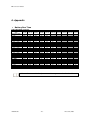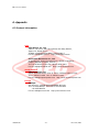
1
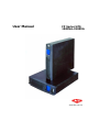
User Manual
FP Series UPS
1000VA-3200VA
www.allis.com.tw
FP series user manual
Contents
Safety information ..........................................................................................................I
Limited product warranty and policy ................................................................................II
1. Presentation.............................................................................................................. 1
1.1 General description............................................................................................ 1
1.2 System configurations........................................................................................ 2
1.2.1 Rack mount............................................................................................. 2
1.2.2 Tower standalone..................................................................................... 3
1.2.3 Single voltage battery design .................................................................... 4
•
Battery Pack(BP) ................................................................................ 4
•
Battery Modules(BM)........................................................................... 4
•
Battery Modules With Charger(BMc) ...................................................... 4
1.3 Front panel....................................................................................................... 5
1.4 Rear panel........................................................................................................ 6
•
FP 1000/ FP1500/ FP 2200/ FP 3000 (UL)..................................................... 6
•
FP1000/ FP1600/ FP2500/ FP3200 (CE)........................................................ 7
•
Extended Battery Module............................................................................ 9
2. Installation ............................................................................................................. 10
2.1 Unpacking ...................................................................................................... 10
2.2 Installation in rack position............................................................................... 13
•
Immovable ............................................................................................. 13
•
Removable ............................................................................................. 14
2.3 Installation in tower position............................................................................. 15
2.4 LCD orientation ............................................................................................... 16
2.5 Connection to communications.......................................................................... 17
2.5.1 Connection............................................................................................ 17
2.5.2 Standard .............................................................................................. 18
•
RS-232............................................................................................ 18
2.5.3 Optional Interface Cards ......................................................................... 19
2.5.3.1 DB9 Dry Contact Card ................................................................... 19
2.5.3.2 USB Card .................................................................................... 20
2.5.3.3 AS400 Card ................................................................................. 21
2.5.3.4 SNMP/HTTP Agent ........................................................................ 22
•
USHA Pro/ USHA ProE................................................................. 22
•
Net Agent Ⅱ ............................................................................. 23
3. Operation ............................................................................................................... 24
3.1 Display and Controls........................................................................................ 24
3.2 Starting up/shutting down the UPS.................................................................... 26
3.3 Operating Modes ............................................................................................. 27
3.4 Configuration Settings ..................................................................................... 29
•
Green Mode ............................................................................................ 29
•
Output Voltage ........................................................................................ 30
3.5 Cruiser Software ............................................................................................. 31
•
Introduction............................................................................................ 31
•
Installation ............................................................................................. 32
Allis Electric
Rev3. July 2005
FP series user manual
Contents
4. Maintenance ...........................................................................................................
4.1 General Maintenance .......................................................................................
•
Environment ...........................................................................................
•
Storing the UPS and battery .....................................................................
•
When to replace the battery......................................................................
4.2 Battery Pack Replacement ................................................................................
4.3 Testing new batteries .......................................................................................
4.4 Recycling the used battery ...............................................................................
4.5 Fuse replacement ............................................................................................
5. Troubleshooting .......................................................................................................
5.1 Audible alarms and status ................................................................................
5.2 Troubleshooting Guide .....................................................................................
6. Appendix ................................................................................................................
6.1 Technical characteristics ...................................................................................
•
Design principle.......................................................................................
•
Components description ...........................................................................
6.2 Specifications .................................................................................................
•
General specifications ..............................................................................
•
Battery Run Time ....................................................................................
6.3 Contact information .........................................................................................
Allis Electric
Rev3. July 2005
36
36
36
36
36
37
38
38
38
39
39
40
41
41
41
41
43
43
46
47
FP series user manual
Safety information
SAVE THESE INSTRUCTIONS. This UPS unit operates from utility power and contains a number of high
current back-up batteries, the information is important to all personnel involved. Please read this manual
first before unpacking, installation and operation of the UPS.
CAUTION: Safety of persons
Opening or removing the cover of the unit may expose you to lethal voltage within the unit even it is apparently
not operated and the input wiring is disconnected from electrical source.
Refer all UPS and battery service to authorized service personnel from the manufacture or agent authorized by
the manufacturer.
Do not dispose battery in a fire. The battery may explode.
Do not open or mutilate the battery. Release electrolyte is harmful to skin and eyes. It may be toxic.
The following precautions should be observed when working on batteries:
• Remove watches, rings, and other metal objects.
• Use tools with insulated handles.
CAUTION: Product Safety
Install the UPS in a clean environment, free from moisture, flammable gases or fumes and corrective
substances.
Keep the UPS on a flat, stable surface with adequate space around it for proper ventilation.
Operate the UPS in an indoor environment only in an ambient temperature range of 32oF to +104oF (0oC to
+40oC).
The UPS is designed for data processing equipment. It is not intended for use with life support and other
designated “critical” devices.
Maximum load must not exceed that shown on the UPS rating label.
Storing magnetic media on top of the UPS may result in data loss or corruption.
Once batteries have reached the end of their life, ensure they are disposed properly. REFER TO YOUR LOCAL
LAWS AND REGULATIONS FOR BATTERY DISPOSAL REQUIREMENTS.
The UPS must be handled with care and attention since the high energy stored within the batteries. It must
always be kept in the position marked on the external packaging and must not be dropped.
Please keep unobstructed air in the exhaust holes of UPS.
The battery should be maintained on a regular time schedule.
CAUTION: Special Precautions
The UPS should be installed according to the instructions in this manual. Failure to do so could result in safety
issues. It could also invalidate your warranty.
DO NOT CONNECT equipment that could overload the UPS or demand half-wave rectification from the UPS, for
example: electric drills, vacuum cleaners, printers or hair dryers.
Adjust only those controls that are listed by the Adjustment Section. If the unit does not operate normally by
following the operating instructions, contact the sales representatives.
Icon Usage
These icons may be found in the content.
WARNING: Obvious danger to personnel or equipment.
CAUTION: Possible danger to personnel or equipment
Important information
Allis Electric
-I-
Rev3. July 2005
FP series user manual
Limited product warranty and policy
Limited Product WarrantyAEC warrants this equipment, when properly applied and operated within specified
conditions, against faulty materials or workmanship for a period of 24 months after the date
of purchase. For equipment located outside Taiwan, AEC only covers faulty parts. AEC
products repaired or replaced pursuant to this warranty shall be warranted for the
unexpired portion of the warranty applying to the original product. This warranty applies
only to the original purchaser.
This warranty does not cover shipping costs, installation costs, maintenance and service
items, calibration and adjustment. Repair or replacement of a defective part, or the
crediting to the user of the value thereof, does not extend the original warranty period.
Warranty policyThe warranty shall be void if (a) the equipment is damaged by the customer, is improperly
used, is subjected to an adverse operating environment, or is operated outside the limits of
its electrical specifications; (b) the equipment is repaired or modified by anyone other than
AEC or AEC-approved personnel; or (c) has been used in a manner contrary to the product’s
operating manual or other written instructions. All claims under this warranty must be
submitted in writing to AEC within 30 days of the occurrence or the claim will not be
considered. This warranty does not include damage resulting from accident or misuse.
AEC reserves the right to determine whether the damage to the connected equipment is
due to malfunction of the AEC product by requesting the equipment in question to be sent
to AEC for examination. This policy is above and beyond, only to the extent needed, of that
provided by any coverage of connected equipment provided by other sources, including,
but not limited to, any manufacturer's warranty and/or any extended warranties.
EXCEPT AS PROVIDED ABOVE, AEC MAKES NO WARRANTIES, EXPRESS OR IMPLIED,
INCLUDING WARRANTIES OF MERCHANTABILITY AND FITNESS FOR A PARTICULAR
PURPOSE.
EXCEPT AS PROVIDED ABOVE, IN NO EVENT WILL AEC BE LIABLE FOR DIRECT, INDIRECT,
SPECIAL, INCIDENTAL OR CONSEQUENTIAL DAMAGES ARISING OUT OF THE USE OF THIS
PRODUCT, EVEN IF ADVISED OF THE POSSIBILITY OF SUCH DAMAGE. Specifically, AEC is
not liable for any costs, such as lost profits or revenue, loss of equipment, loss of use of
equipment, loss of software, loss of data, costs of substitutes, claims by third parties or
otherwise. Coverage also does not apply to connected medical and industrial equipment.
To receive service under this warranty, you must be the original purchaser/user of the
product in question. You must obtain a Returned Material Authorization (RMA) number from
AEC. Products must be returned to AEC with transportation charges prepaid and must be
accompanied by a brief description of the problem encountered and proof of date and place
of purchase.
The policy of AEC is one of continuous improvement. Specifications are subject to change
without notice.
Allis Electric
- II -
Rev3. July 2005
FP series user manual
1. Presentation
1.1 General description
In today’s world where power requirements are increasing, utility power quality and
reliability is decreasing. Normal everyday routines are constantly exposed to power
problems such as power outages, sags, or surges. Any of these problems can spell disaster
for the unprepared. Down time resulting form power problems costs industries billions of
dollars over the course of a year. Industrial and commercial end-users need to be prepared
when the power that they rely on is also a potential problem.
One way to protect critical systems from power outage and sags is the FP-series line of
true on-line uninterruptible power supplies (UPS). The FP-series UPS is designed for
optimizing power quality with the ease of installation.
The
•
•
•
•
•
•
•
•
FP series Features:
Double conversion
Continuous battery charger and inverter for primary power path
Constant battery connection to inverter and load
Guaranteed full power operation during power failure
No voltage drop and zero transfer time
Light weight unit
Hot-swappable battery
User-friendly Graphic LCD
Applications :
•
Computers
•
Network Servers
•
Workstations
•
Wireless Communications
•
Other Electronic Peripherals
Allis Electric
-1-
Rev3. July 2005
FP series user manual
1. Presentation
1.2 System configurations
1.2.1 Rack mount
2U (426 W × 88 H × 500 D mm)
4U (426 W × 176 H × 500 D mm)
8U (426 W × 352 H × 500 D mm)
Allis Electric
-2-
Rev3. July 2005
FP series user manual
1. Presentation
1.2.2 Tower standalone
2U (88 W×
× 426 H × 500 D mm)
4U (176 W×
× 426 H × 500 D mm)
6U (264 W×
× 426 H × 500 D mm)
Allis Electric
-3-
Rev3. July 2005
FP series user manual
1. Presentation
1.2.3 Single voltage battery design
Battery Pack(BP)
The 48VDC standard battery pack contains four 4 × 12V7AH
lead-sealed acid batteries. It is used in all FP series UPS models and
is interchangeable with each other.
Battery Modules(BM)
The battery module contains two(2) Battery Packs. The standard 2U
high single module design always for easy configuration when adding
extra battery modules for extended backup times.
Battery Modules With Charger(BMc)
The BMc is a BM with an added battery charger. The charger shortens
the recharge time of the batteries.
Additional battery charger
Allis Electric
-4-
Rev3. July 2005
FP series user manual
1. Presentation
1.3 Front panel
FP1000/FP1500/FP1600
1.
2.
3.
4.
5
1
2
3
4
Vent
Push Buttons
Graphic LCD Display
Input Breaker Switch
• FP1000: 15A 125V (UL) or
10A 250V (CE)
• FP1500: 15A 125V (UL)
• FP1600: 10A 250V (CE)
5. Internal 48VDC Battery Pack
FP2200/FP2500/FP3200
1.
2.
3.
4.
Vent
Push Buttons
Graphic LCD Display
Input Breaker Switch
• FP2200: 20A 125V (UL)
• FP2500: 15A 250V (CE)
• FP3200: 20A 250V (CE)
5. 2U 96VDC Battery Module
5
1
1
2
3
4
FP3000
1. Vent
2. Push Buttons
3. Graphic LCD Display
4. Input Breaker Switch
• FP3000: 30A 125V (UL)
5. 2U 96VDC Battery Module
5
Allis Electric
1
1
2
-5-
3
4
Rev3. July 2005
FP series user manual
1. Presentation
1.4 Rear panel
FP 1000/ FP1500/ FP 2200/ FP 3000 (UL)
FP1000/FP1500
8
1
1.
2.
3.
4.
2
2
Input Receptacle (15A 125V)
Fan
Optional Communication Slot
Standard RS232
3
4
5
6
7
5. Battery Connector
6. Output Fuse (15A 250V)
7. Output Receptacle (NEMA 5-15R)
8. Input cable 6’ (10A 250V)
FP2200
1
1.
2.
3.
4.
Allis Electric
2
3
4
Power Cord 6’ (NEMA 5-20P; 20A 125V)
Output Fuse (15A 250V)
Output Receptacles (NEMA (1)5-15R; (2)5-20R)
Optional Communications Slot
-6-
5
6
7
5. Standard RS232
6. Fan
7. Battery Connector
Rev3. July 2005
FP series user manual
1. Presentation
FP3000
1
1.
2.
3.
4.
5.
2
3
4
5
6
Power Cord 6’ (NEMA L5-30P; 30A 125V)
Output Fuse (15A 250V)
Output Receptacles (NEMA (1)5-15R; (1)L5-30R)
Optional Communications Slot
Standard RS232
7
8
9
6. Battery Circuit Breaker
7. Fan
8. Battery Connector
9. Battery Cable
FP1000/ FP1600/ FP2500/ FP3200 (CE)
FP1000/ FP1600
Australian
8
British
8
French &
German
1
2
3
4
5
6
7
8
1.
2.
3.
4.
Allis Electric
Input Receptacle (10A 250V)
Fan
Optional Communications Slot
Standard RS232
-7-
5. Battery Connector
6. Output Fuse (10A 250V)
7. Output Receptacle (refer to
8. Input cable 6’ (10A 250V)
Rev3. July 2005
)
FP series user manual
1. Presentation
Output Receptacle options for FP1000/ FP1600.
1.IEC TYPE
2. EUROPE TYPE
FRENCH
BRITISH
5
6
GERMAN
AUSTRALIAN
FP2500/ FP3200
Australian
10
British
10
French &
German
10
1
1.
2.
3.
4.
5.
2
3
Input Receptacle (15A 250V)
Output Fuse (15A 250A)
Output Receptacles (refer to
Optional Communication Slot
Standard RS232
4
)
7
8
6. Battery Circuit Breaker
7. Fan
8. Battery Connector
9. Battery Cable
10. Input Cable 6’ (16A 250V)
Output receptacle options for FP2500/ FP 3200.
1.IEC TYPE
2. EUROPE TYPE
FRENCH
Allis Electric
-8-
BRITISH
GERMAN
AUSTRALIAN
Rev3. July 2005
9
FP series user manual
1. Presentation
Extended Battery Module
How to plug in the battery connector ?
Before plugging in battery connector, please make sure the UPS unit is off.
This is a critical action to ensure the safety of the installer.
How to add on the additional BM or BMc ?
1
3
2
1. Battery Connector
2. Standard Battery Cable
3. Additional Battery Cable
Allis Electric
-9-
Rev3. July 2005
FP series user manual
2. Installation
2.1 Unpacking
The FP-Series UPS can be supplied in a number of boxes depending upon the model ordered.
The number of boxes should be as follows:
MODEL (Box 1)
BATTERY MODULE (Box 2)
FP1000/FP1500/FP1600
N/A (internal battery pack)
FP2200/FP2500/FP3000/FP3200
1 Battery Module
TOTAL BOXES
1 Box
2 Boxes
The UPS and its shipping box are both labeled with the same bar code and
serial number. If the UPS has a problem, then please have the
information on the label ready and contact your sales representative.
Allis Electric
- 10 -
Rev3. July 2005
FP series user manual
2. Installation
FP1000/FP1500/FP1600
Shipping Box
1
4
2
3
5
Mounting- feet × 2
6
Rack-mount × 2
7
Shipping Box Includes:
1. UPS
2. RS-232 communications cable
3. Cruiser software installation CD
4. User Manual (CD)
5. 2pcs mounting-feet for tower configuration
6. 2pcs 19” rack ears (+screws) for rack-mount configuration
7. Power Cord (for FP1000/FP1500/FP1600 only)
Allis Electric
- 11 -
Rev3. July 2005
FP series user manual
2. Installation
FP 2200/FP2500/FP3000/FP3200
Box 1
(Please refer to Shipping Box contents included in
FP1000/FP1500/FP1600 previous page)
Box 2
2
3
4
5
1
Box 2 Includes:
1. BM (or BMc)
2. 2pcs Extension link for tower configuration
3. 2pcs 19” rack ears (+screws) for rack-mount configuration
4. A steel link to connect the UPS and BM (or BMc)
5. Battery cable
Allis Electric
- 12 -
Rev3. July 2005
FP series user manual
2. Installation
2.2 Installation in rack position
Immovable
The rack-mount ears WILL NOT support the
weight of the UPS nor the battery module.
They are used for mounting the UPS and
battery module onto the rack. Mounting rails
are required for each UPS or battery module. If
rails are not installed on the rack, then please
contact your service representative to order a
rail kit.
1. Align the mounting ears and secure with the supplied
screws.
2. Slide the UPS or battery module onto the fixed mounting
rails.
3. Secure the mounting ears to the posts.
4. Repeat the above steps for each UPS and battery module
until installation is complete.
Allis Electric
- 13 -
Rev3. July 2005
FP series user manual
2. Installation
Removable
Optional slide rails are available. Please contact your sales representative for more details.
1. Align the mounting ears and secure with the supplied screws.
2. Fasten the inner parts of the slide rails to the UPS or battery
module with the screws provided.
3. Secure slide rails to posts. As a precaution , fixed mounting rails
should be installation below the slide rails.
4. Slide the UPS or battery module into the slide rails.
5. Repeat the above steps for each UPS and battery module until
installation is complete.
Allis Electric
- 14 -
Rev3. July 2005
FP series user manual
2. Installation
2.3 Installation in tower position
The mounting feet feature as flexibility in configuration and are able to add on the other Battery
module using extendible links to meet long runtimes requirement.
(3)
(4)
(2)
(3)
(1)
(5)
(4)
(2)
(3)
(1)
(2)
(1)
Allis Electric
- 15 -
Rev3. July 2005
FP series user manual
2. Installation
2.4 LCD orientation
The graphic LCD display has been designed so that it can be easily oriented for tower or
rack-mount configuration.
Make sure that the UPS is shutdown before beginning. Ensure that the
input breaker switch is in the OFF position.
1. Remove the top cover.
2. Detach the cables from the input breaker.
3. Remove the front panels.
4. Remove the screws from the display board and rotate the display board clockwise 90 degree for
rack-to-tower configuration or counter-clockwise 90 degree for tower- to-rack configuration.
Allis Electric
- 16 -
Rev3. July 2005
FP series user manual
2. Installation
2.5 Connection to communications
2.5.1 Connection
Standard RS-232 Connection
Optional USB Card Connection
Allis Electric
- 17 -
Rev3. July 2005
FP series user manual
2. Installation
2.5.2 Standard
RS-232
The UPS unit is supplied with a RS-232 cable to connect a local computer or modem to a
remote computer installed with the “Cruiser” software. It can be used to monitor or control
the UPS locally or remotely. Please refer to the chapter 3.5 Cruiser software or the Cruiser
installation disk for details.
The pins of the connector are as following:
PIN #
PIN Definition (UPS)
2
Transmitted data
3
Received data
4
DTE Ready
5
Signal Ground
PIN Definition (PC)
Received data
Transmitted data
DTE Ready
Signal Ground
The RS-232 interface setting are as follows:
Baud Rate
Data Length
Stop Bit
Parity
Allis Electric
2400 bps
8 bits
1 bit
None
- 18 -
Rev3. July 2005
FP series user manual
2. Installation
2.5.3 Optional Interface Cards
The spare communication slot can be used with optional interace
cards such as DB9 Dry Contact Card, USB Card, AS400 Card, and
SNMP/HTTP Card.
2.5.3.1 DB9 Dry Contact Card
For Novell
The DB9 Dry Contact Card offers three relay outputs for customwired application. The figure below shows the interface for the
system connection:
Pin Definition of DB9 for NOVELL Interface
PIN # of DB9
Function explanation
POWER FAILURE - normally open state, will become
2
closed during active state.
POWER FAILURE - normally closed state, will
3
become open during active state.
4
Reference GND for pin 2,3 and 5.
BATTERY LOW - normally open state, will become
5
closed during active state.
Remote shut-down UPS - keep this pin at high
6
voltage (+5V~+12V), needs 500 ms to shut down
UPS. Activates at battery mode.
FAULT - normally open state, will become closed
8
during UPS fault.
Allis Electric
- 19 -
I/O
OUTPUT
OUTPUT
OUTPUT
OUTPUT
INPUT
OUTPUT
Rev3. July 2005
FP series user manual
2. Installation
For Mechanical Dry Contact
The DB9 Dry Contact Card offers three relay outputs for
custom- wired application. The figure below shows the
interface for the system connection:
PIN Definition of DB9 for Mechanical Dry Contact interface
PIN # of DB9
Function explanation
BATTERY LOW - normally closed state, will become
1,2
open during active state. (PIN 2 is common)
POWER FAILURE - normally open state, will become
3,5
closed during active state. (PIN 5 is common)
POWER FAILURE - normally closed state, will
4,5
become open during active state. (PIN 5 is
common)
Remote shut-down UPS - keep this pin at high
6,7
voltage (+5V~+12V), needs 500 ms to shut down
UPS. Activates at battery mode.
FAULT - normally close state, will become open
8,9
during UPS fault. (PIN 9 is common)
I/O
OUTPUT
OUTPUT
OUTPUT
INPUT
OUTPUT
2.5.3.2 USB Card
When the connected computer only has USB ports, an optional USB 1.0 can be used in the
communication slot. A USB cable is supplied with the card.
Allis Electric
- 20 -
Rev3. July 2005
FP series user manual
2. Installation
2.5.3.3 AS400 Card
FP-Series provide slot for AS/400 card. The AS/400 Integration of Lotus Notes is a
blending of the administration, management, and security of the most popular business
application system, the AS/400, with the world's leading messaging and groupware
product, Lotus Notes.
For more details about AS/400, please visit IBM’S
website ”www.ibm.com”
Allis Electric
- 21 -
Rev3. July 2005
FP series user manual
2. Installation
2.5.3.4 SNMP/HTTP Agent
USHA Pro
USHA ProE
USHA (UPS SNMP and HTTP Agent) – USHA allows a user to obtain the status of and issue
commands to the UPS. The UPS can be managed through the use of SNMP managers or Web
browsers. USHA also provides shutdown programs for different operating systems. Shutdown
commands can be sent for such events as power failure, low UPS battery condition, UPS overload,
UPS overheating and scheduled shutdowns. All shutdown events are configurable by the user.
The shutdown software follows an automatic orderly shutdown to prevent the abnormal shut-off
of clients or servers.
The internal card version (USHA Pro) is designed for UPS models, which have the extension board
slot where USHA can be inserted and connected to the UPS through the golden fingers as in Figure
1-1. The external box version (USHA ProE) is designed for UPS models that are not equipped with
the extension board slot; connection between USHA and the RS-232 communication port of UPS
is through a serial cable as shown in Figure 1-2.
Figure 1-1: USHA Pro
Figure 1-2: USHA ProE
For more details about USAH Pro, please refer to the USHA Pro
installation CD.
Allis Electric
- 22 -
Rev3. July 2005
FP series user manual
2. Installation
Net Agent Ⅱ
(External)
(Internal)
NetAgent II allows a user to obtain the status of and issue commands to the UPS. It also
provides other functions such as connecting to a modem to monitor the UPS when a permanent
connection to the internet is not available. Monitoring the status of such things as temperature,
humidity, water conditions, smoke detectors, gas detectors, and door and window detectors is
also possible with NetAgent II when it is connected to optional components. This product is for
“Contact Closure” and ”RS232” interface UPS. The communications protocol includes the
MegaTec/ PPC/ SEC 2400 / 9600. And user could also provide their own protocol to build in.
NetAgent II provides a simple and easy installation procedure. User only needs to install the
software in the NetAgent II CD on a Windows environment to configure the IP address.
All the other configurations could be accomplished in a Web browser. NetAgent II also provides
shutdown programs for different operating systems. Shutdown commands can be sent for such
events as power failure, low UPS battery condition, UPS overload, UPS overheating and scheduled
shutdowns. All shutdown events are configurable by the user. The shutdown software provides
an orderly shutdown to prevent the abnormal shut-off of clients or servers.
For more details about NetAgent II, please refer to the NetAgent II
installation CD.
Allis Electric
- 23 -
Rev3. July 2005
FP series user manual
3. Operation
3.1 Display and Controls
The diagram below show the basic functions of the front panel on all FP series UPS.
FUNCTION/TEST
LCD DISPLAY
SET/ALARM SILENCE
ON/OFF
SYMBOLS USED ON GRAPHIC LCD DISPLAY
INPUT BREAKER
Alarm: When the UPS fails, the symbol will flash.
Green Mode: When UPS is in Green Mode, the symbol will flash.
Fault: When the UPS has failed and must be repaired, the symbol will flash.
Test: When UPS is conducting Battery Self-Test under Normal Mode, the symbol will
flash.
Load: The higher the load, the more bars will illuminate.
Inverter: When Inverter is normal, the symbol will illuminate.
Power Factor Corrector (PFC): When PFC is normal, the symbol will illuminate.
Input Power: When utility power is normal, the symbol will illuminate.
Charger: When charger is in normal operation, the symbol will illuminate.
Booster: When UPS starts Battery Booster, the symbol will illuminate.
Battery: The bars indicate an approximate amount of battery charge remaining.
Each bar represents 25% of battery capacity.
High–speed Fan: UPS is in Battery Mode.
Medium–speed Fan: UPS is in Normal Mode.
Low–speed Fan: UPS is in Bypass Mode.
Allis Electric
- 24 -
Rev3. July 2005
FP series user manual
3. Operation
CONTROLS
INPUT BREAKER SWITCH
• This switch disconnects the input power to the UPS.
FUNCTION/TEST BUTTON
This button has two functions:
1. Manual Battery Test
•
When the UPS is working under normal conditions, press this button to self-test the
battery for 10 seconds. During this test, the battery will supply the UPS with power.
If the battery are supplying unstable voltages, then the audible alarm will produce
one long beep and the UPS will switch to receiving power from the utility source.
2. Configuration UPS Settings
•
When pressed together with the SET/ALARM SILENCE button for three seconds,
allows the user to configure UPS settings.
SET/ALARM SILENCE BUTTON.
This button has three functions
1. Silence Alarms
•
Press this button for one second and the alarms will be silenced. After the alarm is
silenced, the UPS cannot audibly alert users of any additional problems.
Overheating, PFC Over-current, Inverter over-current, Overload, Battery
mode, Low battery in battery mode, and charger failure alarms cannot be
silenced.
2. Change Selection
•
Pressing the button for second will allow the user to view various parameters and
measurements including Input Voltage, Output Voltage, Output Frequency, Battery
Voltage, percent of Load, percent of Input current, Internal Temperature of the unit,
and Output Current.
3. Configuration Settings
•
When pressed together with the FUNCTION/TEST button for three seconds, allows
the user to configure UPS settings.
ON/OFF BUTTON.
This button controls output power to the load and has two functions:
1. Force UPS into Bypass Mode.
2. Start UPS from battery when utility power in not available.
When the UPS is in Normal Mode operation, pressing the ON/OFF button
once will put UPS into Bypass Mode. Pressing this button again will force
the UPS back to Normal Mode. If utility power is not available and UPS is
not connect with higher than 3% load, then the UPS will shut down after
30-40 seconds.
Allis Electric
- 25 -
Rev3. July 2005
FP series user manual
3. Operation
3.2 Starting up/shutting down the UPS
Normal Start-up of the UPS
Step 1. Plug the UPS into an AC power source.
Step 2. Turn on the Input Breaker switch. The UPS will begin its start-up process by first
going into Bypass Mode and then into Normal Mode. After entering the Normal
Mode, the UPS is ready for operation.
Shutting down the UPS
Step 1. Press ON/OFF key for one second. The UPS will switch to Bypass Mode.
Step 2. Turn off the Input Breaker switch. Display will turn off.
During shutdown, do not press any buttons. Pressing a button may
cause the UPS to re-energize and deliver output power.
Battery Start-up of the UPS
To turn on the UPS without using utility power, press the ON/OFF button.
supplying power through its batteries.
Allis Electric
- 26 -
The UPS will begin
Rev3. July 2005
FP series user manual
3. Operation
3.3 Operating Modes
NORMAL MODE
During normal operation, utility power provides energy to the UPS. The UPS converts the
utility power to computer-grade power for the connected loads. The UPS will also maintain
the batteries at a fully charged state.
All indicators are stable except Alarm. The graphic LCD display
shows indicators of load, Inverter, PFC, Input power, Charger, Battery,
Fan in medium speed, Green Mode, Fault, and Test. A solid line
shows the power flow from input to the load and batteries. The
display will also show the status of the measuring parameters by
pressing the SET/ALARM SILENCE button.
BATTERY MODE
Battery Mode occurs in the event of a utility power failure or an extreme input voltage
condition. The batteries will supply power to the connected load through the DC/DC
converter and the DC/AC inverter. When utility power is restored, the UPS switches to
Normal Mode operation and recharges the batteries. While in Battery Mode, an alarm will
beep. The beeping frequency will continue to increase as an indication that the batteries are
running low and that the UPS is about to shut down. If the UPS shuts down, then it will
automatically restart when utility power is restored.
In Battery Mode, a solid line will be lit from the Battery symbol to
Booster and Inverter symbols. The High-speed Fan symbol will also
be lit. The battery bars will indicate the remaining battery capacity.
As capacity decreases, the number of bars will also decrease.
For approximate battery run times, please refer to the Battery Run
Time chart at the end of this manual. The run time is based on
resistive load and an ambient temperature of 77°F (25°C). To
increase the run time, turn off non-essential equipment or add an optional external battery
module.
Allis Electric
- 27 -
Rev3. July 2005
FP series user manual
3. Operation
BYPASS MODE
In the event of a UPS overload or internal failure, an audible alarm will sound and the UPS will
switch to Bypass Mode where utility power is powering directly to the connected loads.
However, Battery Mode won’t occurs availably when the UPS:
• Is overheating.
• Has an overload condition of 101 to 110% for more than 120 seconds.
• Has an overload condition of 111 to 150% for more than 20 seconds.
• Has an overload condition greater than 150%.
• Detects a fault in the battery or UPS electronics.
In Bypass Mode, solid lines will be lit from the Input Power symbol to
the Load symbol and from the Input Power symbol to the Charger and
Battery symbols. The Low-speed Fan symbol will also be lit.
GREEN MODE
When the UPS has Green Mode enabled, it will switch to Bypass Mode when the connected
load is less than 3% of the UPS rating. The graphic LCD display will show Bypass Mode with
the Green Mode symbol flashing. If the load is over 3% of the UPS rating, then the UPS will
operate in Normal Mode with the Green Mode symbol lit. To enable or disable Green Mode,
please refer to the Configuration Settings section of this manual or contact your service
representative.
Allis Electric
- 28 -
Rev3. July 2005
FP series user manual
3. Operation
3.4 Configuration Settings
Press the FUNCTION/TEST button and SET/ALARM SILENCE button at same time
for one second. Alarm will sound one beep; the unit is in Configuration Mode.
There are eight Bit columns at the bottom of the graphic LCD
display. From left to right, they are identified as Bit 7 to Bit 0.
When the UPS is in Configuration Mode, Bit 0 will be lit. Press the
FUNCTION/TEST button to move between Bit 0 to Bit 6. When
changing from Bit 0 to Bit 6, check to see if Bit 7 is lit. If it is, then
that located Bit is set. Pressing the SET/ALARM SILENCE button
will toggle between set and unset.
Bit 7
Bit 6
Bit 5
Bit 4
Bit 3
Bit 2
Bit 1
Bit 0
Bit Definition Table
Key Button
Setting
SET/Alarm
Status Setting
Button
Green Mode
Function
Button
Bit Definition
Bit 7
Bit 3
Output
UPS INVERTER Voltage
OUTPUT
Bit 1
VOLTAGE
Bit 0
On=lit Off=unlit
On: Disable Green Mode
Off: Enable Green Mode
208V
220V
230V
240V
(100V) (110V) (115V)
(120V)
Off
Off
On
On
Off
On
Off
On
Green Mode
Enable/Disable Green Mode
1. Pressing the FUNCTION/TEST and SET/ALARM SILENCE buttons at the same time for 1
second. Alarm will sound one beep; the UPS is in configuration mode .
2. Press the FUNCTION/TEST button until Bit 3 is lit. If Bit 7 is lit, then Green Mode is
disabled. If Bit 7 is unlit, then Green Mode is enabled.
3. To change the setting, press the SET/ALARM SILENCE button once.
4. After changing to the desired setting, press the FUNCTION/TEST and SET/ALARM
SILENCE buttons at same time for one second. An audible beep will sound and the Green
Mode setting is set.
Allis Electric
- 29 -
Rev3. July 2005
FP series user manual
3. Operation
Output Voltage
NEVER change the voltage settings when the UPS is ON and
powering connected loads.
1. Press FUNCTION/TEST and SET/ALARM SILENCE buttons at the same time for one second.
A short beep will signal that UPS is ready for configuration settings.
2. Press the Function/Test button until Bit0 or Bit 1 is lit. If the Bit0 and Bit1 are lit, then
output voltage is 240V for FP1000/ FP1600/ FP2500/ FP3200 or Output voltage is 120V for
FP1000/FP1600/FP2200/FP3000.
3. To change the setting, press the SET/ALARM SILENCE button once.
Example: Change output voltage form 100V to 120V
1. Press the FUNCTION/TEST button until Bit 0 is lit.
Bit 7
Bit 6
Bit 5
Bit 4
Bit 3
Bit 2
Bit 1
Bit 0
●
Bit 1
Bit 0
●
Bit 1
●
Bit 0
2. Press the SET/ALARM SILENCE button so that Bit 7 is lit.
Bit 7
●
Bit 6
Bit 5
Bit 4
Bit 3
Bit 2
3. Press the FUNCTION/TEST button so that Bit 1 is lit.
Bit 7
Bit 6
Bit 5
Bit 4
Bit 3
Bit 2
4. Press the SET/ALARM SILENCE button so that Bit 7 is unlit.
Bit 7
●
Bit 6
Bit 5
Bit 4
Bit 3
Bit 2
Bit 1
●
Bit 0
5. Press the FUNCTION/TEST and SET/ALARM SILENCE buttons at the same time
for one second. A short beep will signal that the UPS has returned to normal
display.
6. Restart the UPS.
1. New settings for Green Mode will take effect immediately. For all
other settings, please restart the UPS due to safe reason.
2. Setting the output voltage to 100 VAC will de-rate the VA and Watt
ratings listed in the specifications of the UPS.
Allis Electric
- 30 -
Rev3. July 2005
FP series user manual
3. Operation
3.5 Cruiser Software
Introduction
The Cruiser software has been designed with user-friendly operating status & icons to be
easier acknowledge and operation. Cruiser can send warning messages to a pager, via
e-mail or over a LAN. thus providing an early warning system for power failures, system
shutdown and a variety of other scenarios. It allows a faster response time, even when the
user is not locally available.
Features
• Green Mode support
• PFC status display
• Cross platform support
• UPS monitoring utility
• Scheduled system shutdown
• Graphic display of UPS status
• Warning notification via
e-mail or pager
• Customized controls
• User-definable warnings
• Multi-language versions
• “Read & Write” functions
when setting output voltage
and frequency (optional)
System Requirements
•
•
•
•
•
•
•
•
•
•
IBM compatible computer
Windows 95/NT4.0/98SE/ME/2000/XP and 2003
Linux Red Hat 7.0~7.3, 8.0 and 9.0
Linux Mandrake 8.2 and 9.0
32MB RAM
20MB available hard-drive space
TCP/IP protocol
Internet connection
RS232 serial port or USB port
CD-ROM drive (for installation)
Interface & OS Compatibilities
RS232
Windows: Win95, WinNT4.0, Win98SE,
Win2000, WinMe, WinXP
Linux: 7.0~7.3, 8.0~8.4, 9.0
Mandrake: 8.2, 2.3, 8.4, 9.0
Novell: 4.x, 5.1
Allis Electric
USB
Windows: Win98SE, Win2000.
WinMe, WinXP
- 31 -
Rev3. July 2005
FP series user manual
3. Operation
Installation
1. Insert the Cruiser CD into the CD-ROM Drive.
2. The setup program will automatically run. If it does not, then simply double-click on the
setup.exe file on the CD. (Note1)
3. Follow all the on-screen instructions.
Step 1:
Allis Electric
Click Next to continue.
- 32 -
Rev3. July 2005
FP series user manual
3. Operation
Step 2:
Type in User Name and Company Name.
Step 3:
Type in the Serial Number.
Allis Electric
- 33 -
Rev3. July 2005
FP series user manual
3. Operation
Step 4:
Choose the Destination Folder
Step 5:
Restart the computer.
Allis Electric
- 34 -
Rev3. July 2005
FP series user manual
3. Operation
Step6: After finishing the installation, the setup process will create the Cruiser
program group in Programs Files and add its icon
to System task bar. Right
will pop up its program menu.
click on Cruiser icon
•
•
•
•
•
•
•
Allis Electric
Hide/Show Monitoring Window:
This function is to hide/show the Cruiser's monitoring window.
On-line Help File:
This option is to launch the on-line help file which will help you to use Cruiser well.
About Cruiser:
This option is to show the information about Cruiser.
Exit:
This option is to close Cruiser and remove it from your computer memory.
When the UPS communication with PC via RS232, the optional slot can’t be
installed any card.
Close others software concerning using the COM1 port if it is running on
Quick Start.
- 35 -
Rev3. July 2005
FP series user manual
4. Maintenance
4.1 General Maintenance
The FP-Series UPS requires very little maintenance. The batteries are sealed,
valve-regulated, maintenance-free and enclosed in a fire-retardant pack. The batteries
should be kept charged to maintain their designed lifetime. When utility power is
supplied to the UPS, it will continuously charge the batteries.
Environment
For the best preventive maintenance, keep the area around the UPS clean and
dust-free.
Please keep unobstructed air in the exhaust holes of UPS.
Operate the UPS in an indoor environment with an ambient temperature range of 32°F
to +104°F (0°C to +40°C).
Keep the UPS on a flat, stable surface with adequate space around it for proper
ventilation.
Do not place the unit near a heat source and avoid placing the unit in direct sunlight.
Do not place the unit near water or excessive moisture.
Storing the UPS and battery
When storing the UPS for any length of time, it is recommended to plug in the UPS for at
least 24 hours every four to six months to ensure full battery recharge.
When to replace the battery
It is suggested that the battery pack be replaced every two years to ensure that the UPS
provides full backup capacity during a blackout. Batteries should be checked every two
to three months by pressing the FUNCTION/TEST button to conduct a test in Normal
Mode. If the UPS produces a long beep and switches back to Normal Mode within ten
seconds, then the batteries may need replacing. Contact your service representative to
order a new battery pack or battery module.
Allis Electric
- 36 -
Rev3. July 2005
FP series user manual
4. Maintenance
4.2 Battery Pack Replacement
With the hot-swappable battery pack design, the FP-Series UPS batteries can be easily
replaced without turning off the UPS or disconnecting the load. The batteries can also be
replaced by shutting down the UPS first. This is done by pressing the ON/OFF button for one
second and letting the UPS switch to Bypass Mode; then turn off the Input Breaker switch
and unplug the UPS.
1. Loosen and remove the screws on the left side of the front panel. Remove the panel
from the unit.
2. Loosen and remove the screws of battery stoppers.
3. Hold the battery pack and pull it out of the front of the unit.
4. Line up and slide in the new replacement battery pack.
5. Gently push the battery pack until a tight connection is made with the unit.
6. Re-install the battery stoppers with the screws.
7. Re-install the panel to the unit with the screws.
Do not disconnect the batteries while the UPS is in battery mode!
Allis Electric
- 37 -
Rev3. July 2005
FP series user manual
4. Maintenance
4.3 Testing new batteries
Start up the UPS with load added. Press the FUNCTION/TEST button for three seconds to
activate the self-test. If the UPS switches back to Normal Mode after 10 seconds, then the
batteries are good. If it does not, then please check the battery cable or connections.
Contact your sales representative for assistance.
4.4 Recycling the used battery
Do not discard the UPS, the battery pack, or batteries into the trash. Contact your local
recycling or hazardous waste center for information on proper disposal of used battery pack
and batteries.
Consider all warnings, cautions, and notes before replacing batteries.
Batteries can present a risk of electrical shock and high short circuit
current. The following precautions should be observed when working on
batteries:
Remove watches, rings, and other metal objects.
Use tools with insulated handles.
Do not lay tools or metal parts on top of batteries.
Do not attempt to alter any battery wiring or connectors. Attempting
to alter wiring can cause injury.
Do not dispose of batteries in a fire. The batteries may explode.
Refer to your local codes for disposal requirements.
Do not open or mutilate the battery or batteries. Released electrolyte
is harmful to the skin and eyes. It may be toxic.
4.5 Fuse replacement
The output fuse is located at the rear of the UPS. Before changing the fuse, turn off the UPS
and unplug the input cable from the AC source.
1. Press and rotate the fuse holder counter-clockwise.
2. Replace the fuse with one of similar type and rating. Re-install the assembly into
the UPS. Press and rotate the fuse holder clockwise until it locks into position.
3. Reconnect the input power cord to the input AC source.
4. Restart the UPS.
Allis Electric
- 38 -
Rev3. July 2005
FP series user manual
5. Troubleshooting
5.1 Audible alarms and status
Audible Alarms
Possible Cause
Three short beeps
1. Utility voltage error.
Four short beeps
1. Utility frequency error.
Five short beeps
1. UPS internal overheating.
2. Fan failure.
Six short beeps
1. PFC over-current.
Seven short beeps
followed by three long
beeps
1. Battery backup time running
down.
Long continuous beep
1. Output overload.
2. Charger failure.
3. UPS fault.
Action
1. UPS is in Battery Mode,
check the input voltage.
1. UPS is in Battery Mode,
remove the input power
and check the input
frequency.
1. Check the ventilation and
remove any object
blocking air passage.
2. Call for service to replace
the fan.
1. Input AC voltage may be
too low. Disconnect
some load to remove the
alarm.
1. Save any important data
and turn off the computer.
Wait for utility power to
return.
1. Disconnect some load.
2. Call for service.
3. Call for service.
If the above actions do not resolve your problem, then please contact
your sales representative.
Allis Electric
- 39 -
Rev3. July 2005
FP series user manual
5. Troubleshooting
5.2 Troubleshooting Guide
Problem
Possible Cause
UPS will not turn on
1. Input breaker switch is OFF.
2. UPS input breaker has
tripped.
3. Input/battery cables not
connected properly.
UPS will not provide
power to load
1. Power only present on one
output receptacle.
2. No output from output
receptacles.
3. Output fails as soon as load
connected.
1. Input fuse blown.
2. Generator does not power
the UPS.
UPS operates from
battery despite
presence of utility
power
UPS drops the load
Load exceeds UPS rating.
and switches to
Bypass Mode
UPS battery time is
1. Batteries may need
not long enough or
replacing.
the unit does not run
on battery at all
UPS is beeping
1. Refer to audible alarms
table.
UPS in Bypass Mode 1. UPS has not started in
after disabling Green
Normal Mode.
Mode.
Button on front panel 1. UPS in start-up mode.
does not work
2. Button damaged.
Allis Electric
- 40 -
Action
1. Ensure that the UPS Input
breaker is switched ON.
2. Ensure the connected load is
less than the UPS rating.
3. Ensure that input cable and
battery cables are securely
fitted into the UPS and
battery module. Check that
the battery breaker is
switched ON.
1. Check the output fuse.
2. Check the connected cable.
3. Load exceeds maximum UPS
rating. Remove some load.
1. Replace input fuse.
2. Check that the generator is
properly governed for both
frequency and voltage. Some
low-grade generators will not
supply power stable enough
to run a UPS.
1. Disconnect some load from
UPS.
1. Press Function/Test button. If
UPS switches to Normal Mode
within ten seconds, then
change the batteries.
1. Refer to the audible alarms
table.
1. Press STANDBY button.
Alarm will beep once and UPS
switches to Normal Mode.
1. Wait for start-up to complete.
2. Call service for a Returned
Material Authorization (RMA)
number.
Rev3. July 2005
FP series user manual
6. Appendix
6.1 Technical characteristics
Design principle
Components description
Input filter
This printed board assembly provides surge protection, certified by IEC 61000-4-5 and
IEC 801-5, and filters both electro-magnetic interference (EMI) and radio frequency
interference (RFI). It minimizes surges and interference present in the utility line and
keeps sensitive equipment protected.
Current and power factor regulator
In normal operation, this circuit converts utility AC power to regulated DC power for the
inverter to use. This ensures that the input current has a sinewave form so that current
distortion will not reflect back to the utility. The FP-Series UPS can tolerate a wide input
range and has an overload power factor regulator alarm to alert the user that the UPS
has a heavy output load in abnormal low input voltage to extend the reliability of the
unit.
DC/AC inverter
In normal operation, the inverter utilizes the regulated DC output and inverts it into
precise, regulated sinewave AC power. When the utility power fails, the inverter will
receive its required energy from the battery through the DC/DC converter. In both
modes of operation, the UPS inverter is on-line and continuously generates clean,
precise, regulated AC power for load. Current is very stable even with nonlinear loads.
Allis Electric
- 41 -
Rev3. July 2005
FP series user manual
6. Appendix
Charger
The battery charger uses the energy from the utility power and precisely regulates it to
continuously charge the batteries by “constant power” mode. The batteries are charged
whenever the FP-Series UPS is plugged into utility power. The charger will operate as
long as the input voltage is over 60 VAC.
DC/DC converter
The DC/DC converter utilizes energy from the batteries and boosts up the DC voltage to
the operating voltage for inverter. This allows the inverter to operate continuously at
optimum efficiency and voltage.
Battery
The FP-Series UPS utilizes a flame-retardant battery pack comprised of four 12V 7AH,
valve-regulated, and sealed lead acid batteries. All FP battery packs are interchangeable
and are easy to install or change. To maintain battery life, the UPS should operate in an
ambient temperature of 68°F to 77°F (20°C to 25°C). Battery modules containing two
battery packs are available for extended battery run times.
Transfer switch
The FP-Series UPS provides an alternate path to energize the connected load. If the
UPS has an overload, over input current, over crest-factor load (designed for 3:1
nonlinear loads), failure condition, or is overheating, then it will automatically switch so
that power is being supplied by the utility power. When this occurs, an audible alarm will
sound and a visual indication will be shown on the LCD display.
Output filter
This filter prevents electro-magnetic conductance (EMC) leakage and RFI noise to output.
It minimizes interference present in the inverter and utility line to keep sensitive
equipment protect.
Allis Electric
- 42 -
Rev3. July 2005
FP series user manual
6. Appendix
6.2 Specifications
General specifications
The principal operating characteristics of the FP-Series UPS at 25°C ambient operating
temperature is shown below.
MODEL
FP1000
FP1600
FP2500
FP3200
INPUT
Input Voltage
230 V (160 ~ 276 V)
(Nominal input voltage)
Nominal input Frequency
50 / 60 Hz ±5 Hz
Input PFC
>0.98 @ full load
OUTPUT
Power
1000VA/700W 1600VA/1120W 2500VA/1750W 3200VA/2240W
Output Voltage
208V / 220V / 230V / 240V
(Output Voltage Regulation)
(Rated Voltage ± 2% )
Output Frequency
50/60HZ (Auto-tracking)
High Efficiency Mode
>86%
>86%
>88%
>88%
(AC to AC)
Output T.H.D
<3% at linear load
Overload Capacity
Sustaining 50sec @ 108% load; 28sec @ 110~120% load;
15sec @ 120~130% load; 9sec @ 140~145% load;
Immediate Response @ 150%
Crest ratio
3:1
Transfer Time
Zero for power failures or recoveries.
<4msec for UPS to Bypass or reverse.
BATTERY
Battery Packs
1×48VDC
1×48VDC
2×48VDC
2×48VDC
Typical Backup Time
(Full/Half load)
Battery Type
Recharge Time to 90%
Extended Battery Cabinet
Battery Pack
Battery Pack
Battery Pack (96V)
Battery Pack (96V)
8/25 minutes
7/18 minutes
8/20 minutes
6/17 minutes
Sealed VRLA 12V7AH; Hot-Swappable
8 hours
Extended Battery Module in 2U high
(comprises 2×48VDC Battery Packs)
MECHANICAL
Dimensions-Rackmount
426 × 88(2U) × 426 × 88(2U) ×
(W×H×D in mm)
500mm
500mm
Weight(UPS / Battery Packs) 12/11.2 kgs
12/11.2 kgs
Total Weight
23.2 kgs
23.2 kgs
Conformance
EMI/RFI Compatibility
Safety Certifications
Allis Electric
426 × 176(4U) 426 × 176(4U)
× 500mm
× 500mm
13.2/31.2 kgs
13.4/31.4 kgs
44.4 kgs
44.6 kgs
EN50091-2 Class B, EN50091-2 Class B, EN50091-2 Class B, EN50091-2 Class B,
EN55022B
EN55022B
EN55022B
EN55022B
CE , TUV / GS
- 43 -
CE , TUV / GS
CE , TUV / GS
CE , TUV / GS
Rev3. July 2005
FP series user manual
6. Appendix
MODEL
FP1000
FP1500
FP2200
FP3000
INPUT
Input Voltage
120 V
(Nominal input voltage )
(80 ~ 138 V)
Nominal input Frequency
50 / 60 Hz ±5 Hz
Input PFC
>0.98 @ full load
OUTPUT
Power
1000VA/700W 1500VA/1050W 2200VA/1540W 3000VA/2100W
Output Voltage
100V / 110V / 115V / 120V
(Output Voltage Regulation)
(Rated Voltage ± 2% )
Output Frequency
50/60HZ (Auto-tracking)
High Efficiency Mode
>86%
>86%
>88%
>88%
(AC to AC)
Output T.H.D
<3% at linear load
Overload Capacity
Sustaining 50sec @ 108% load; 28sec @ 110~120% load;
15sec @ 120~130% load; 9sec @ 140~145% load;
Immediate Response @ 150%
Crest ratio
3:1
AC/AC Efficiency
>86%
Transfer Time
Zero for power failures or recoveries.
<4msec for UPS to Bypass or reverse.
BATTERY
Battery Packs
1×48VDC
1×48VDC
2×48VDC
2×48VDC
Typical Backup Time
(Full/Half load)
Battery Type
Recharge Time to 90%
Extended Battery Cabinet
Battery Pack
Battery Pack
Battery Pack (96V)
Battery Pack (96V)
8/25 minutes
7/18 minutes
8/20 minutes
6/17 minutes
Sealed VRLA 12V7AH; Hot-Swappable
8 hours
Extended Battery Module in 2U high
(comprises 2×48VDC Battery Packs)
COMMUNICATIONS INTERFACE
Communications port
RS-232 Port (Standard); DB9, AS400, USB Card (optional)
SNMP Manageable
Yes
MECHANICAL
Dimensions-Rackmount
16.8 × 3.5(2U) 16.8 × 3.5(2U)
× 19.7
× 19.7
(W×H×D in inches)
Weight(UPS/Battery Module) 26.4/24.7 lbs. 26.4/24.7 lbs.
Total Weight
51.1 lbs.
51.1 lbs.
16.8 × 7(4U) 16.8 × 7(4U) ×
× 19.7
19.7
29/67.8 lbs.
29.5/69.2 lbs.
97.8 lbs.
98.2 lbs.
Conformance
EMI/RFI Compatibility
Safety Certifications
FCC Class B*
UL
FCC Class B*
UL
FCC Class B*
UL
FCC Class B*
UL
* This equipment has been tested and found to comply with the limits for a Class B digital device, pursuant to Part 15 of
the FCC Rules. These limits are designed to provide reasonable protection against harmful interference when the
equipment is operated in a commercial environment. This equipment generates, uses, and can radiate radio frequency
energy and, if not installed and used in accordance with the instruction manual, may cause harmful interference to radio
communications. Operation of this equipment in a residential area is likely to cause harmful interference in which case the
user will be required to correct the interference at his own expense.
Allis Electric
- 44 -
Rev3. July 2005
FP series user manual
6. Appendix
MODELS: FP1000-FP3200
CONTROL FRONT PANEL
Buttons
STANDBY, FUNCTION and SET
Indications
Fault, Charger, PFC, Green, Line, Booster, Inverter,
Bypass, Load at 25/50/75/100%, Batteries at
25/50/75/100%.
Audible Alarms
DC Mode, Low Battery, Voltage Error, Frequency Error,
Charger Failure, Overheating, Overload, Fault,
PFC Overload.
COMMUNICATIONS INTERFACE
Communications port
RS-232 Port (Standard); DB9, AS400, USB Card
(optional)
SNMP Manageable
Yes
ENVIRONMENT
Operating Temperature
0°C~+40°C (32°F~104°F)
Storage Temperature
-15 ~ +50°C
Audible Noise (1 meter
≤45dBA
from surface of unit)
Relative Humidity
0%~95% (non-condensing)
Allis Electric
- 45 -
Rev3. July 2005
FP series user manual
6. Appendix
Battery Run Time
RUN TIME CHART in Minutes
Output load 200 VA
400 VA
(140 W) (280 W)
UPS Model
FP 1000
59
32
+1 BM
260
134
+1BM + 1BMc
466
247
+2BM + 1BMc
358
FP 1500
63
34
+1 BM
274
142
+1BM + 1BMc
491
260
+2BM + 1BMc
377
FP 1600
67
38
+1 BM
279
148
+1BM + 1BMc
505
266
+2BM + 1BMc
380
FP 2200
242
88
+1 BMc
373
241
+1BM + 1BMc
487
+1BM + 2BMc
FP 2500
247
92
+1 BMc
379
244
+1BM + 1BMc
491
+1BM + 2BMc
FP 3000
253
94
+1 BMc
383
246
+1BM + 1BMc
493
+1BM + 2BMc
FP 3200
255
95
+1 BMc
385
247
+1BM + 1BMc
495
+1BM + 2BMc
-
600 VA
(420W)
800 VA
(560W)
18
83
166
250
19
88
175
264
21
93
179
268
62
184
244
364
65
186
249
366
67
189
153
367
69
190
156
369
12
58
124
183
13
62
131
193
15
64
135
196
42
98
172
243
47
107
179
255
49
109
182
259
50
111
183
261
1000 VA 1500 VA 2000 VA 2500 VA 3000 VA 3200 VA
(700 W) (1050 W) (1400 W) (1750 W) (2100 W) (2240 W)
8
50
91
146
9
53
96
154
10
55
98
157
31
75
140
195
34
78
142
197
36
79
147
202
36
81
148
204
7
31
60
92
8
33
62
94
12
43
62
101
15
44
66
104
18
49
69
106
19
50
70
107
9
27
52
66
9
29
53
68
11
29
54
69
12
30
55
70
8
20
41
58
8
21
42
59
9
21
43
60
6
16
31
49
7
17
32
50
Indicates time not calculated, contact sales representative for details.
Allis Electric
- 46 -
Rev3. July 2005
6
16
30
48
FP series user manual
6. Appendix
6.3 Contact information
Asia
Allis Electric Co., Ltd.
12th F1., No.19-11, San-Chung Road, Nan Kang District,
Taipei 115, Taiwan R.O.C.
Tel:886-2-2655-3456 Fax:886-2-2655-2286~7
E-mail: [email protected]
http://www.allis.com.tw
Sheen Asia Electronics Co., Ltd.
2F, Building A2, Beiwei Industrial Area, GETDD, Guangzhou,
People's Republic of China, 510730
Tel:+86-20-8222 1370/1 Fax:+86-20-8222-1419
E-mail: [email protected] http://www.sheenasia.com
North America
IMP Enterprises, inc.
18218 East McDurmott, Suite E, Irvine, California 92614, U.S.A
Tel:+1-949-477-9198 Fax:+1-949-477-9195
E-mail: [email protected] http://www.impenterprises.com
Europe
AEC SpA
Via Vesuvio 1 I-20054 NOVA MILANESE MI, Italy
Tel:+39-0362364535 Fax:+39-02-700-427499
+39 0362366059
E-mail: [email protected] http://www.aeceuro.com
Allis Electric
- 47 -
Rev3. July 2005