1
3/4
H.P.
CAPAC|TOR
115 Volts,
60
Cycles, 3450
MODEL
This is the Model
on the nameplate
Number
Number
NUMBER
113.12260
of Your Craftsman Motor_ _f w_t4 be found
attached
to the motor. A_ways mention
when communicating
with us regarding
the M.ode_
your motor or when
ordering ports_
HOW
TO
ORDER
REPAIR
PARTS
All pa_ts, listed herein mc_y be ordered through
COo or SIMPSONS_SEARS LI
SEARS. ROEBUCK AND
. When ordering
the mai_ order house which se_ves the territory
parts by mo_/from
_n which you live_ seffing
prices will be furnished on request or ports wiff be sh_pped at prevailing prices and you wHJ be billed accardinglyo
WHEN ORDERING REPAIR PARTS, ALWAYS GIVE THE FOLLOWING
_NFORMAT_ON AS SHOWN
IN THtS LIST:
i, The PART NUMBER_
3_ The MODEL
2, The PART NAME_
4, The NAME
COAST
TO
COAST
SERV!CE
FOR
YOUR
NUMBER--_i3,12260,
of
1terns3
4 H, P, Mo_or,
NATiON-WIDE
FROM
SEARS
CRAFTSMAN
SEARS,
MOTOR
ROEBUCK
AND
CO,
and
SFMPSONS-SEARS LBMiTED in Canada
_ck
up your
_nvestment with qukk,
expert mech_nka_
_ne CRAFTSMAN
service _nd ge_uo
replacement
p_rts.
_f and when you need repairs or service_ c_N on _s to protect
your _nvesto
menf _n th_s fine piece of eq,dipmenf.
SEARS, ROEBUCK
CANADA,
SiMPSONS-SEARS
CO.-
U. S. A.
LIMITED
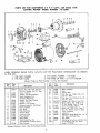
PARTS
LIST
FOR
ELECTRIC
CRAFTSMAN
3/4
H. P. CAPA_JOR
MOTOR--MODEL
START
TYPE
_ 13. ! 2260
i
4
567
8
13
2
3
22 23
24
25
15
WHEN ORDERING REPAIR PARTS, ALWAYS
iN THiS LIST:
I. THE PART NUMBER
2. THE PART NAME
Always
Key
No.
Part
No.
1
448011
2
3
4
37576
30779
37593
5
6
7
8
9
10
11
12
13
14
15
16
30766
30768
37021
37579
64027
23428
30783
37574
37567
37568
37582
37597
17
37189
*Standard
Order
GiVE THE FOLLOWING
ffems--May
AS SHOWN
3, THE MODEL NUMBER--113.12260
4, THE NAME OF ITEM--3/4
H. P. MOTOR
by Part Number-
*Screw, No. 8_32 x 3/8, Type 23,
Pan Hd., Started, Cad, Pl., Steel
Cover, Termln ai
Washer, Off Sling (Rubber)
Shleld Assembly, End
(Terminal Plate End)
Washer, End Play (Plastic)
Washer, Thrust
Retainer, Trust Washer
Actuator Assembly, Centrifugal
Rotor Assembly
Key, Shaft
Ring, Retaining
Guard, Shaft
Card and Plug
Plug, Adaptor
Stud, Stator
Shie.Jd As_mbly,
End
(End Opposite Terminal Cover)
Plug, Conduit
Hardware
iNFORMATION
not by Key Number
NO.
No.
Key
Part
18
19
20
21
64028
37585
37180
120611
22
120614
23
24
9417373
132128
25
26
37594
169752
27
28
29
37587
37588
30790
30
30789
Not
64029
Shown
be Purchased Locally.
2
Stator Assembly
Base
Clamp, _se
*Nut, _.,
No. 10_32x 3/8 x 1/8,
Cad. Pi., Steel
*Nut, Hex., No. 10_32 x 3/8 x 1/8,
Cad. Pi., Steel
*Washer, No..203 x 7/i6x
i/32
*Screw, Mach., No. 10-32 x 7/8,
Fil. Hd. Slaffed, Cod. Pi., Steel
Switch Assembly, Starter
*Screw, No. i0-32 x 1/4, Type C,
Pan Hd., Slotted, Cod. Pi,, Steel
Cover, Capacitor
Capacitor
Bushing (to Adapt Shaft from 1/2n to
5/8" Dia. with Shaft Key)
Key, Shaft
Operating instructions and Parts List
for Craftsman 3/4 H. P. Motor
Model 113,12260
MOUNTING, CONNECTION AND
CRAFTSMAN
MOTOR--
MAINTENANCE
MODEL
No.
FOR
creases bearing life. L_ose beffs reduce operating efficiency and shorten be_t iffe.
This Craftsman Motor is of the capacitor-start type designed
for use on a single-phase, 60-cycle, alternating°current
supply of 115 volts, with a simpie means of reversing the
direction of rotation provided, The motor may be operated
in any position.
MOUNTING
iNSTRUCTiONS
i i 3.i:2260
7. After the motor base has been properly adiusted to
the mounting bracket, tighten al_ motor mounting bobs
secure_y_
NOTE: in order to prevent accumulation of
static electric charges due to belt friction, the
motor frame or base should be grounded to
a water or steam pipe. A metallic connection
should also be provided between the motor
and the device being driven.
THE MOTOR
1. This motor was given a thorough electrical and mecham
ical inspection before it was shipped from the factory.
in order to make sure that no damage has occurred
during shipment, the following check procedure should
be made before mounting the motor in the particular
application for which it was purchased.
a, Rotate the shaft with the fingers to make sure it turns
freely and smoothly.
b_ Clamp motor base to work bench or table and remove
key from shaft. Connect motor to the proper voltage
supply temporarily in accordance with instructions
under "Connecting
the Motor". When energized,
the motor shoWd operate with only a smaii amount
of electrical "hum" and very low bearing noise.
c. Notice direction of shaft rotation to make sure it is
correct for the equipment to be driven. _f direction
of rotation is not correct, reverse rotation as outiined
in instructions listed under "'Connecting
the Motor "°.
Reoinstall the key in motor shaft.
& included with this motor is a new molded shaft guard
that can be easily twisted into place over the unused
shaft extension as an extra: safety feature.
CONNECTING
THE MOTOR
CAUTION: This motor wili be damaged if
connected to a current source other than 60_
cycle affernating<urrent
(ac).
1. The motor must be operated on ! 15-voff, 60-cycle a<
power when connected as outlined in instructions that
follow. Motor wires are color coded to make connec_
tions easy to accomplish.
2. A 484rich, 3<onductor (center ground wire) cord and
plug assembly is attached at the factory, with the two
power leads connected to the quick connect tabs adiacent to termina_ posts "T_ " and _'T¢" . (See figure 40 In
event this cord is removed and the motor wked for a
permanent installation,
connect one power lead to
terminal "T_" (or quick connect tab adiacent to it), Connect the other power _ead to termina_ "T4" {or quick
connect tab adiacent to it)
2. Disconnect the motor from temporary power source and
mount it in the application for which it was purchased.
3. The motor should be installed _n a location as cool and
dry as possible and should be protected against excessive deposits of dust and dirt. (See figure I for mounting
dimensions.) The motor must not be confined in a small
space that will restrict the flow of cooling air over
internal elec:trlcal windings.
3. Connections between motor and power s_urce should
be made through o switch and fuse block. Use a 20ampere fuse for ! 15-voffs. }:uses of the delayed_acfion
type, such as "Fustat" or "Fusetron" are recommended,
as they are designed for best motor protection.
4. The wire sizes listed beiow are recommended for circu{t
connections between motor and power supply, or extem
SiGn cords (_f used/.
4. Before tightening the motor mounting bohs_ make sure
at_ four mounting points of the base are in contact with
the surface to which the motor is being attached, if the
motor base does not contact the mounting surface properly, the base (or support) may be warped or cracked
when mounting bolts are tightened.
Length
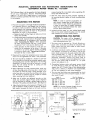
5. Make sure all puiieys are tightened securely on their
shafts and correctly aligned. Proper pulley a_gnment
may be obtained by holding a straight edge across the
flat sidesof: the pulteys and adiusting to it. (See figure 2.)
of
Three-Cenducfer
100
100
150
200
6. Adiust the belt tension so that pressure of fingers on the
belt will deflect it readily as shown in figure 3. Excessive
belt tension increases the load on the motor and de-
feet
feet
feet
feet
E×tens_en
or
to
to
to
Wire
lAmer{can
Jess
150 feet
200 feet
400 feet
Size
Required
W;re
Gauge
No.
No.
No.
No.
12
10
8
6
No_)
NOTE: For circuits of greater length, the wire
size must be increased proportionoffy.
ST £AIGN?
EIDGE
1 iS
VOLT
LIN[
T__A
_ULL_Y
I
Figure 2
/4
1" 4 _
i _5 VOL'_
L_N_
PLUG AND COED ATTACHED TO
_[H_S_ TA_S A_ THE FACTORY
_2_3/S .......................
Figure
Figure 3
!
3
Figure 4
_]B
MA:<E _URE _X
Every effort should be ma_e ra _revent foreign material
from entering the mo_:
.....
_'_,_r_ied under conditions likely to roerm_ , c_ ,
-._ of dust, dirt, or
waste within the maTo__, _
.;_ection should be
.made at frequent intervals, nccumuiations of dry dust
can usually be blown out successfully.
'VOLT
L I_"@
NOTE:
Motors
used on wood°working
tools
are particularly
susceptible
to the accumulation
of sawdust and wood
chips and should
be
SG_OU_<D_C
Figure
5
Figure
blown
out, or 'Vacuumedfrequently
to preveto interference
with normal motor ventilation
6
and proper operation
atec{ starting switch.
OiL
Figure
HOLE
OIL
HOLE
5,
Most motor troubles may be traced to .loose or incorrect
connections; to overloading; to reduced input voltage
which results when small size wires are used in the supply
circuit, or when the supply circuit is very long. Always
check connections, load and supply circuit when the
motor foils to perform satisfactorily. Although the motor
is designed for operation on voltage and frequency
specified on motor nameplate, normal loads will be
handled safely on voltages not more than l@_'_ove
or below the nameplate voltage. Heavy loads, however, require that voltage at motor terminals be not
less than the voltage specified on nameplate.
6_
Common Causes of Low Voltage Are:
o. Overloadlng
of house or shop circuits with lights,
e_ectricol appilances or other motors.
7
5. The Black and Red motor leads are connected to the
quick connect tabs on terminal board. (See figure 4.)
NOTE: To reverse direction of rotation, inter°
change position of B!ock and Red motor leads.
WARNING:
Do not change any of these connections with current on.
6. This motor is equipped with a 3-prong connector plug
(Underwriters ' Laboratory approved) as a safety measure. The longest of the three prongs is connected to the
motor housing through the power cord. When the p_ug
is inserted into a properly grounded receptacle, the
user is protected from electrical shock, should the motor
insulation fail for any reason. When using on extension
cord, make sure it is also a 3-wire cable.
CAUTION: Many existing receptacle boxes do
not have provision for 3oprong plugs and for
this reason an adapter is included with the
motor. (This adapter is not used in Canada.) To
use the adapter, connect the grounding lead to
the box before operating motor (See figure 5).
1_ The sleeve bearings
have been lubricated
cant. No other part
circuits
or extension
cords,
General overloading of the power company's faciJb
ties. (In many sections of the country, demand for
electrical power exceeds the capacity of existing
generating and distribution systems. If it is suspected
that voltage being suppJled is Jew, request a voltage
check from the power company.)
overheats.
for long periods of
Frequent opening of fuses or circuit breakers. (This
may also result if motor is overloaded, or if the
motor circui_ is fused with a fuse other tha_ those
recommended. Do not use a fuse of greater capacity
without consu ring the power cornpanyd
2. Re-Jubrlcate motor bearings occasionally at the oil hole
located near the rap of the hub on each end shield, (See
figure 7.1 Be sure to wipe off dirt or grit if present
around oil holes to prevent any possibility of foreign
materla[ contaminating
the oil wicks that supply the
bearings with oil Use a good grade of medium weight
mineral oil, such as automobile engine oil SAE 20.
GUARANTEE
This Craftsman Motor was thoroughly
inspected and
tested before shipment. Should it foil due to faulty material
or workmanship, we will repair or replace it, at our option,
free of charge if returned to your Sears retail or mail-order
store wlthln one year from date of purchase. This guarantee is void if the motor has been tampered with, misused
or abused, or if either end shield has been removed in the
process of servicing by anyone other than an authorized
serv :e station. External parts such as the terminal cover
may be removed or replaced without voiding the guarantee.
3. If disassembly of the motor is necessary, it should be
returned to your nearest Sears retail or mail-order store
in order to prevent voiding the guarantee.
Form No. 2925
,,vires in supply
d. Motor burns out when operated
time when overloaded.
in both end shields of this motor
at the factory
with correct lubriof the motor requires lubrication.
cannot
Undersized
C_
c. Motor
AND
NOTE: The speed of this motor
regulated or changed.
b,
7, Some Effects of Low Voltage Are:
a. Motor fails to develop full power. (The power output of motor decreases rapidly with decrease in
voltage at motor terminals. For example: a reduction
of 10% in voltage causes a reduction of 19% in
maximum power output of which the motor is capable,
while a reduction of 20% in voltage causes a reduction of 36% 'n maximum power output.)
b. Motor starts slowly or fails to come up to full speed.
7. The motor may be operated with a reversing switch
(9M2982 in catalog), provided connections are made as
shown in figure 6. The motor must come to a complete
stop before reversing can be accomplished. If motor
rotation does not correspond to switch notations, interchange switch leads 2 and 4_
LUBRICATION
of the centrifugafly-oper-
be
4