1
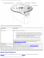
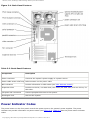
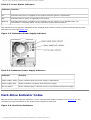
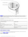
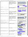
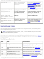
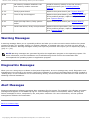
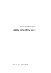
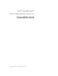
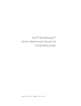
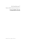
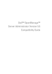
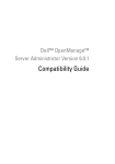
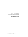
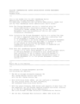
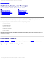
Indicators, Codes, and Messages: Dell PowerEdge 1600SC Systems Service Manual
Back to Contents Page
Indicators, Codes, and Messages
Dell™ PowerEdge™ 1600SC Systems Service Manual
Front-Panel Features
System Messages
Back-Panel Features
System Beep Codes
Power Indicator Codes
Warning Messages
Hard-Drive Indicator Codes
Diagnostics Messages
NIC Indicator Codes
Alert Messages
Applications, operating systems, and the system itself are capable of identifying problems and alerting you to
them. When a problem occurs, a message may appear on the monitor or a beep code may sound.
A variety of messages can indicate when the system is not operating properly:
●
System messages
●
System beep codes
●
Warning messages
●
Diagnostics messages
●
Alert messages
The system indicators and front- and back-panel features are illustrated in this section. This section also
describes each type of message and lists the possible causes and actions you can take to resolve any problems
indicated by a message.
Front-Panel Features
Figure 3-1, Figure 3-2, and Figure 3-3 show the system's front-panel features. Table 3-1 describes the frontpanel controls and indicators.
Figure 3-1. System With Non-Hot-Plug Hard Drives
http://support.jp.dell.com/docs/systems/pe1600sc/en/sm/beep.htm (1 av 14)2004-12-10 10:48:14
Indicators, Codes, and Messages: Dell PowerEdge 1600SC Systems Service Manual
Figure 3-2. System With Hot-Plug SCSI Hard Drives
Figure 3-3. Front-Panel Controls and Indicators
http://support.jp.dell.com/docs/systems/pe1600sc/en/sm/beep.htm (2 av 14)2004-12-10 10:48:14
Indicators, Codes, and Messages: Dell PowerEdge 1600SC Systems Service Manual
Table 3-1. Front-Panel Controls and Indicators
Component
Description
Power button
Turns system power off and on.
●
●
If you turn off the system using the power button and the system is
running an ACPI-compliant operating system, the system can perform
an orderly shutdown before power is turned off. If the power button is
pressed for more than four seconds, the system power will turn off
regardless of the current operating system state.
If the system is not running an ACPI-compliant operating system,
power is turned off immediately after the power button is pressed.
The power button is enabled in the System Setup program. When disabled,
the button can only turn the system power on. For more information, see
"Using the System Setup Program" and the operating system's
documentation.
Reset button
Restarts the system.
Power indicator
Provides information on power status (see "Power Indicator Codes").
Hard-drive activity indicator
Indicates read or write access to a hard drive.
Diskette and CD drive indicators Indicate read or write access to the respective drive.
Back-Panel Features
Figure 3-4 shows the back-panel features of the system. Table 3-2 describes the back-panel features.
http://support.jp.dell.com/docs/systems/pe1600sc/en/sm/beep.htm (3 av 14)2004-12-10 10:48:14
Indicators, Codes, and Messages: Dell PowerEdge 1600SC Systems Service Manual
Figure 3-4. Back-Panel Features
Table 3-2. Back-Panel Features
Component
Description
Power connector
Connects the system's power supply to a power source.
Power cable strain relief loop Relieves strain on the power cable.
NIC indicators
Provide information on NIC status (see "NIC Indicator Codes").
Expansion slots
Provide two 64-bit, 100-MHz slots, two 64-bit, 66-MHz slots, and two 32-bit, 33MHz slots.
I/O ports and connectors
Connect peripheral devices to the system.
Kensington lock
Secures the system.
Power Indicator Codes
The power button on the front panel controls the power input to the system's power supplies. The power
indicator can provide information on power status (see Figure 3-3). Table 3-3 lists the power button indicator
codes.
http://support.jp.dell.com/docs/systems/pe1600sc/en/sm/beep.htm (4 av 14)2004-12-10 10:48:14
Indicators, Codes, and Messages: Dell PowerEdge 1600SC Systems Service Manual
Table 3-3. Power Button Indicators
Indicator Function
On
Indicates that power is supplied to the system and the system is operational.
Off
Indicates that no power is supplied to the system.
Blinking
Indicates that power is supplied to the system, but the system is in a standby state. For
information on standby states, see the operating system documentation.
The indicators on the optional redundant power supplies show whether power is present and whether a power
fault has occurred (see Figure 3-5).
Figure 3-5. Redundant Power Supply Indicators
Table 3-4. Redundant Power Supply Indicators
Indicator
Function
Power supply status Green indicates that the power supply is operational.
Power supply fault
Amber indicates a problem with the power supply.
AC line status
Green indicates that a valid AC source is connected to the power supply.
Hard-Drive Indicator Codes
Each hard-drive carrier has two indicators: a busy indicator and a status indicator (see Figure 3-6). The
indicators provide information on the status of the respective hard drive.
Figure 3-6. Hard-Drive Indicators
http://support.jp.dell.com/docs/systems/pe1600sc/en/sm/beep.htm (5 av 14)2004-12-10 10:48:14
Indicators, Codes, and Messages: Dell PowerEdge 1600SC Systems Service Manual
Table 3-5 lists the drive-status indicator codes. Different codes display as drive events occur in the system. For
example, in the event of a hard-drive failure, the "drive fail" code appears. After the drive is selected for
removal, the "preparing for removal" code appears. After the replacement drive is installed, the "preparing for
operation, drive online" code appears.
The drive-busy indicator signifies whether the hard drive is active on the SCSI bus. This indicator is controlled by
the hard drive.
Table 3-5. Hard-Drive Status Indicator Codes
Drive-Status Indicator
Indicator Code
Drive bay empty
Off
Drive being prepared for operation, drive online
Steady green
Drive being identified, prepared for removal, or drive
offline
Blinks green three times per second at equal intervals
Drive rebuilding
Blinks green once per second
Drive failed
Steady amber
NIC Indicator Codes
The NIC connector on the back panel has an indicator that provides information on network activity and link
status (see Figure 3-7). Table 3-6 lists the NIC indicator codes.
Figure 3-7. NIC Indicators
http://support.jp.dell.com/docs/systems/pe1600sc/en/sm/beep.htm (6 av 14)2004-12-10 10:48:14
Indicators, Codes, and Messages: Dell PowerEdge 1600SC Systems Service Manual
Table 3-6. NIC Indicator Codes
Indicator
Indicator Code
Link and activity indicators are off.
The NIC is not connected to the network.
Link indicator is green.
The NIC is connected to a valid link partner on the network.
Activity indicator is amber blinking. Network data is being sent or received.
System Messages
Table 3-7 lists the system error messages that can occur and the probable cause for each message.
NOTE: If you receive a system message that is not listed in Table 3-7, see the documentation for the
application that is running when the message appears and/or the operating system documentation for an
explanation of the message and recommended action.
Table 3-7. System Messages
Message
Causes
Corrective Actions
Address mark not found
Faulty CD drive, diskette drive,
or hard-drive; faulty system
board.
Replace the system board (see
"System Board").
Alert! Back system fan was
not detected.
Specified fan is missing, faulty,
or improperly installed.
Check the fan cable connection. If the
problem persists, replace the fan (see
"System Fans").
Alert! Cover was previously
removed!
The chassis has been opened.
Information only.
Alert! Previous back system
fan failure.
Specified fan failed before last
system startup (see Figure 4-6 to
identify the fans).
Information only.
Alert! CPU n fan was not
detected.
Alert! Front system fan was
not detected.
Alert! Previous CPU n fan
failure.
Alert! Previous front
system fan failure.
http://support.jp.dell.com/docs/systems/pe1600sc/en/sm/beep.htm (7 av 14)2004-12-10 10:48:14
Indicators, Codes, and Messages: Dell PowerEdge 1600SC Systems Service Manual
Alert! Previous voltage
failure.
Power supply failed before last
system startup.
Information only.
Alert! Processor thermal
probe failure detected.
Microprocessor fan is missing,
faulty, or improperly installed.
Check the fan cable connection. If the
problem persists, replace the heat-sink
assembly (see "Microprocessors").
Alert! Unsupported memory
or incomplete sets in the
following bank(s): Bank n
Faulty memory module(s).
Ensure that the memory is installed
correctly (see "Memory Module
Installation Guidelines"). Remove and
reseat the memory modules (see
"Memory Modules"). If the problem
persists, replace the memory module
(see "Memory Modules").
Amount of available memory
limited to 256 MB!
OS Install Mode is enabled in
the System Setup program.
Disable OS Install Mode in the
System Setup program (see "Using
the System Setup Program").
Attachment failed to
respond
Diskette-drive or hard-drive
controller cannot send data to
the associated drive; faulty or
improperly installed diskette
drive or hard drive.
Check the interface cable connections
to the drive and system board. If the
problem persists, replace the diskette
drive or hard drive (see "Diskette
Drive" or "Hard Drives").
Auxiliary device failure
Loose or improperly connected
mouse or keyboard cable; faulty
mouse or keyboard.
See "External Visual Inspection."
Bad error-correction code
(ECC) on disk read
Faulty CD/diskette-drive
subsystem or hard-drive
subsystem; faulty system board.
Replace the system board (see
"System Board").
BIOS Update Attempt Failed!
Remote BIOS firmware update
attempt failed.
Retry the BIOS firmware update.
Caution! NVRAM_CLR jumper
is installed on system
board. Please run setup.
NVRAM-clear jumper is installed.
Remove the NVRAM-clear jumper (see
Figure 5-2 for jumper location). Check
the System Setup configuration
settings (see "Using the System Setup
Program").
Data error
Faulty diskette, diskette drive,
CD drive, tape drive, or hard
drive.
Replace the diskette or CD. Check the
interface cable connections to the
drive and system board. If the
problem persists, replace the diskette
drive, CD drive, or hard drive (see
"Diskette Drive," "5.25-Inch Drives,"
or "Hard Drives").
Decreasing available memory
Faulty or improperly installed
memory modules.
Ensure that the memory is installed
correctly (see "Memory Module
Installation Guidelines"). Remove and
reseat the memory modules (see
"Memory Modules"). If the problem
persists, replace the memory module.
Diskette drive seek failure
Incorrect configuration settings
in the System Setup program.
Run the System Setup program to
correct the settings (see "Using the
System Setup Program").
Controller has failed
http://support.jp.dell.com/docs/systems/pe1600sc/en/sm/beep.htm (8 av 14)2004-12-10 10:48:14
Indicators, Codes, and Messages: Dell PowerEdge 1600SC Systems Service Manual
Faulty or improperly installed
diskette drive.
Check the interface cable connections
to the drive and system board. If the
problem persists, replace the diskette
drive (see "Diskette Drive").
Diskette read failure
Faulty or improperly inserted
diskette.
Replace the diskette.
Diskette subsystem reset
failed
Faulty or improperly installed
diskette drive.
Check the interface cable connections
to the drive and system board. If the
problem persists, replace the diskette
drive (see "Diskette Drive").
Diskette write protected
Diskette write-protect feature
activated.
Move the write-protect tab on the
diskette to the disabled position.
Drive not ready
Diskette missing or improperly
inserted in diskette drive.
Reinsert or replace the diskette.
Gate A20 failure
Faulty keyboard controller; faulty
system board.
Replace the system board (see
"System Board").
General failure
Operating system corrupted or
improperly installed.
Reinstall the operating system.
Hard disk controller
failure
Incorrect configuration settings
in System Setup program;
improperly installed hard drive;
loose interface or power cable;
faulty hard-drive controller
subsystem.
Run the System Setup program to
correct the drive type setting (see
"Using the System Setup Program"). If
the problem persists, check the
interface cable connections to the
drive and controller. If the problem
persists, replace the hard-drive
controller card or system board (see
"System Board").
Invalid memory
configuration detected.
Potential corruption
exists!
Memory module installation
guidelines have not been
properly followed.
See "Memory Module Installation
Guidelines."
Keyboard controller failure
Faulty keyboard controller; faulty
system board.
Replace the system board (see
"System Board").
Keyboard data line failure
Loose or improperly connected
keyboard cable; faulty keyboard;
faulty keyboard controller.
Check the keyboard cable connection.
If the problem persists, replace the
keyboard. If the problem persists,
replace the system board (see
"System Board").
Faulty or improperly installed
memory modules.
Ensure that the memory is installed
correctly (see "Memory Module
Installation Guidelines"). Remove and
reseat the memory modules (see
"Memory Modules"). If the problem
persists, replace the memory module.
If the problem persists, replace the
system board (see "System Board").
Faulty application program.
Restart the application program.
Keyboard failure
Keyboard stuck key failure
Memory address line failure
at address, read value
expecting value
Memory double word logic
failure at address, read
value expecting value
Memory odd/even logic
failure at start address to
end address
Memory write/read failure
at address, read value
expecting value
Memory allocation error
http://support.jp.dell.com/docs/systems/pe1600sc/en/sm/beep.htm (9 av 14)2004-12-10 10:48:14
Indicators, Codes, and Messages: Dell PowerEdge 1600SC Systems Service Manual
Memory bank population
error!
Memory module installation
guidelines have not been
properly followed.
Ensure that the memory is installed
correctly (see "Memory Module
Installation Guidelines").
Memory parity interrupt at
address
Faulty or improperly installed
memory modules.
Ensure that the memory is installed
correctly (see "Memory Module
Installation Guidelines"). Remove and
reseat the memory modules (see
"Memory Modules"). If the problem
persists, replace the system board
(see "System Board").
Memory tests terminated by
keystroke
The spacebar was pressed during
POST to terminate the memory
test.
Information only.
No boot device available
Faulty diskette, diskette drive,
CD drive, or hard drive.
Check the Integrated Devices
settings in the System Setup program
(see "Using the System Setup
Program."). If the problem persists,
replace the CD drive or diskette drive.
If the problem persists, replace the
system board (see "System Board").
No boot sector on harddisk drive
No operating system on hard
drive.
Check the hard-drive configuration
settings in the System Setup program
(see "Using the System Setup
Program").
No timer tick interrupt
Faulty system board.
Replace the system board (see
"System Board").
Non-system disk or disk
error
Faulty diskette, diskette drive,
CD drive, or hard drive.
Use a bootable diskette. If the
problem persists, replace the CD drive
or diskette drive. If the problem
persists, replace the hard drive (see
"System Board").
Not a boot diskette
No operating system on diskette.
Use a bootable diskette.
One value1 MHz Processor,
L2 Cache: 512KB
Microprocessors with different
speeds are installed. The system
operates at speed of slower
microprocessor.
Replace the slower microprocessor
with one that matches the faster
microprocessor (see
"Microprocessors").
PCI BIOS failed to install
Loose cables to expansion card
(s); faulty or improperly installed
expansion card.
Ensure that all appropriate cables are
securely connected to the expansion
cards. If the problem persists, remove
and reseat the expansion cards (see
"Expansion Cards"). If the problem
persists, replace the expansion card.
Plug & Play Configuration
error
Error encountered while
initializing PCI devices.
Install the NVRAM-clear jumper and
reboot the system (see Figure 5-2 for
jumper location). If the problem
persists, remove and reseat the
expansion cards (see "Expansion
Cards"). If the problem persists,
replace the expansion card.
One value2 MHz processor,
L2 Cache: 512KB
System running at
value1 MHz
http://support.jp.dell.com/docs/systems/pe1600sc/en/sm/beep.htm (10 av 14)2004-12-10 10:48:14
Indicators, Codes, and Messages: Dell PowerEdge 1600SC Systems Service Manual
Primary drive n not found
The primary IDE channel is
enabled in the System Setup
program, but no drive is
attached; improperly installed
hard drive; loose interface or
power cable.
Run the System Setup program to
correct the drive type setting (see
"Using the System Setup Program"). If
the problem persists, check the
interface cable connections to the
drive and controller. If the problem
persists, replace the hard-drive
controller card (see "Expansion
Cards") or system board (see "System
Board").
Read fault
Faulty diskette, diskette drive,
CD drive, or hard drive.
Replace the diskette or CD. Check the
interface cable connections to the
drive and system board. If the
problem persists, replace the diskette
drive, CD drive, or hard drive (see
"Diskette Drive," "5.25-Inch Drives,"
or "Hard Drives").
Reset failed
Improperly connected diskette
drive, tape drive, hard drive, or
power cable.
Ensure that all cables are securely
connected.
ROM bad checksum = address
Faulty or improperly installed
expansion card.
Remove and reseat the expansion
cards (see "Expansion Cards"). If the
problem persists, replace the
expansion card.
Secondary drive n not found
The secondary IDE controller is
enabled in the System Setup
program, but no drive is
attached; improperly installed
hard drive; loose interface or
power cable.
Run the System Setup program to
correct the drive settings (see "Using
the System Setup Program.") If the
problem persists, check the interface
cable connections to the drive and
system board. If the problem persists,
replace the hard drive.
Sector not found
Faulty diskette or hard drive.
Replace the diskette. If the problem
persists, replace the diskette drive
(see "Diskette Drive"). If the problem
persists, replace the hard drive (see
"Hard Drives").
Shutdown failure
Shutdown test failure.
Ensure that the memory is installed
correctly (see "Memory Module
Installation Guidelines"). Remove and
reseat the memory modules (see
"Memory Modules"). If the problem
persists, replace the system board
(see "System Board").
Time-of-day clock stopped
Faulty battery.
Replace the system battery (see
"System Battery"). If the problem
persists, replace the system board
(see "System Board").
Time-of-day not set please run SETUP program
Incorrect Time or Date settings;
faulty system battery.
Check the Time and Date settings
(see "Using the System Setup
Program"). If the problem persists,
replace the system battery (see
"System Battery").
Timer chip counter 2 failed
Faulty system board.
Replace the system board (see
"System Board").
Requested sector not found
Seek error
Seek operation failed
http://support.jp.dell.com/docs/systems/pe1600sc/en/sm/beep.htm (11 av 14)2004-12-10 10:48:14
Indicators, Codes, and Messages: Dell PowerEdge 1600SC Systems Service Manual
Unexpected interrupt in
protected mode
Faulty or improperly installed
memory modules or faulty
system board.
Ensure that the memory is installed
correctly (see "Memory Module
Installation Guidelines"). Remove and
reseat the memory modules (see
"Memory Modules"). If the problem
persists, replace the system board
(see "System Board").
Unsupported CPU stepping
detected
Microprocessor is not supported
by the system.
Update the BIOS firmware.
Utility partition not
available
The <F10> key was pressed
during POST, but no utility
partition exists on the boot hard
drive.
Create a utility partition on the boot
hard drive (see "Using the Dell
OpenManage Server Assistant CD" in
the User's Guide).
Warning! No microcode
update loaded for processor
n
BIOS error.
Update the BIOS firmware.
Write fault
Faulty diskette, CD drive,
diskette drive, hard drive, or
hard-drive subsystem.
Replace the diskette. If the problem
persists, replace the diskette drive or
CD drive. If the problem persists,
replace the hard drive (see "Hard
Drives").
Write fault on selected
drive
System Beep Codes
When an error that cannot be reported on the monitor occurs during a boot routine, the system may emit a
series of beeps that identify the problem.
NOTE: If the system boots without a keyboard, mouse, or monitor attached, the system will not issue
beep codes related to these peripherals.
When a beep code is emitted, record it on a copy of the Diagnostics Checklist and then look it up in Table 3-8. If
you are unable to resolve the problem by looking up the meaning of the beep code, use the system diagnostics
to identify the cause.
Table 3-8. System Beep Codes
Code
Cause
Corrective Action
1-1-2
CPU register test failure
Replace the primary microprocessor (see
"Microprocessors"). If the problem persists, replace
the secondary microprocessor.
1-1-3
CMOS write/read failure; faulty system
board
Replace the system board (see "System Board").
1-1-4
BIOS error
Reflash the BIOS firmware.
1-2-1
Programmable interval-timer failure;
faulty system board
Replace the system board (see "System Board").
1-2-2
DMA initialization failure
1-2-3
DMA page register write/read failure
Remove and reseat the memory modules (see
"Memory Modules"). If the problem persists, replace
the system board (see "System Board").
http://support.jp.dell.com/docs/systems/pe1600sc/en/sm/beep.htm (12 av 14)2004-12-10 10:48:14
Indicators, Codes, and Messages: Dell PowerEdge 1600SC Systems Service Manual
1-3-1
Main-memory refresh verification failure
1-3-2
No memory installed
1-3-3
Chip or data line failure in the first
64 KB of main memory
1-3-4
Odd/even logic failure in the first 64 KB
of main memory
1-4-1
Address line failure in the first 64 KB of
main memory
1-4-2
Parity failure in the first 64 KB of main
memory
1-4-3
Fail-safe timer test failure
1-4-4
Software NMI port test failure
2-1-1 through Bit failure in the first 64 KB of main
2-4-4
memory
3-1-1
Slave DMA-register failure
Replace the system board (see "System Board").
3-1-2
Master DMA-register failure
3-1-3
Master interrupt-mask register failure
3-1-4
Slave interrupt-mask register failure
3-2-2
Interrupt vector loading failure
3-2-4
Keyboard-controller test failure
Check the keyboard cable connection. If the
problem persists, replace the keyboard. If the
problem persists, replace the system board (see
"System Board").
3-3-1
CMOS failure
Replace the system board (see "System Board").
3-3-2
System configuration check failure
3-3-3
Keyboard controller not detected
3-3-4
Video memory test failure
3-4-1
Screen initialization failure
3-4-2
Screen-retrace test failure
3-4-3
Video ROM search failure
4-2-1
No timer tick
4-2-2
Shutdown test failure
4-2-3
Gate A20 failure
4-2-4
Unexpected interrupt in protected mode
Remove and reseat the expansion cards (see
"Expansion Cards"). If the problem persists, replace
the expansion card.
4-3-1
Improperly installed or faulty memory
modules
Ensure that the memory is installed correctly (see
"Memory Module Installation Guidelines"). Remove
and reseat the memory modules (see "Memory
Modules"). If the problem persists, replace the
system board (see "System Board").
http://support.jp.dell.com/docs/systems/pe1600sc/en/sm/beep.htm (13 av 14)2004-12-10 10:48:14
Indicators, Codes, and Messages: Dell PowerEdge 1600SC Systems Service Manual
4-3-2
No memory modules installed in the
first memory module connector
Install a memory module in the first memory
module connector (see "Installing Memory
Modules").
4-3-3
Faulty system board
Replace the system board (see "System Board").
4-3-4
Time-of-day clock stopped
Replace the system battery (see "System Battery").
If the problem persists, replace the system board
(see "System Board").
4-4-1
Super I/O chip failure; faulty system
board
Replace the system board (see "System Board").
4-4-4
Cache test failure; faulty microprocessor
Replace the microprocessor (see "Microprocessors").
If the problem persists, replace the system board
(see "System Board").
Warning Messages
A warning message alerts you to a possible problem and asks you to take corrective action before the system
continues a task. For example, before you format a diskette, a message may warn you that you may lose all
data on the diskette. Warning messages usually interrupt the procedure and require you to respond by typing y
(yes) or n (no).
NOTE: Warning messages are generated by either the application program or the operating system. For
more information, see the Installation and Troubleshooting Guide and the documentation that
accompanied the operating system or application program.
Diagnostics Messages
When you run a test group or subtest in the system diagnostics, an error message may result. Diagnostic error
messages are not covered in this section. Record the message on a copy of the Diagnostics Checklist (located in
"Getting Help" in the Installation and Troubleshooting Guide), and then follow the instructions in that section for
obtaining technical assistance.
Alert Messages
Systems management software generates alert messages for the system. For example, the software generates
messages that appear in the SNMP trap log file. Alert messages consist of information, status, warning, and
failure messages for drive, temperature, fan, and power conditions. For more information, see the systems
management software documentation.
Back to Contents Page
http://support.jp.dell.com/docs/systems/pe1600sc/en/sm/beep.htm (14 av 14)2004-12-10 10:48:14