1
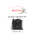
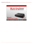
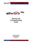
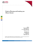
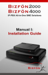
Bizfon 7000
Service and
Troubleshooting Guide
(for Revision 5.2)
Service and Troubleshooting Guide
Table of Contents
1
2
3
4
5
6
Safety Instructions....................................................................................................................................1
1.1 Electrical...................................................................................................................................................1
1.2 Electrostatic Discharge.............................................................................................................................1
Chassis Views...........................................................................................................................................2
Exterior Cleaning ......................................................................................................................................4
Troubleshooting and Repair Procedures................................................................................................5
4.1 Troubleshooting – Start Here....................................................................................................................5
4.2 Troubleshooting a Power Problem............................................................................................................5
4.3 Troubleshooting a Solid Alert Indicator .....................................................................................................6
4.3.1 Reseat All Connectors and Reboot Task ........................................................................................6
4.3.2 Isolate Mirrored Disks Task ............................................................................................................6
4.3.3 Fix Disk Task ..................................................................................................................................6
4.3.4 Fix Application Software Task.........................................................................................................7
4.3.5 Fix Server Configuration Task ........................................................................................................7
4.3.6 Fix Server Database Task ..............................................................................................................7
4.3.7 Fix File System Task ......................................................................................................................8
4.4 Troubleshooting a Flashing Alert Indicator................................................................................................8
4.5 Server Shutdown......................................................................................................................................8
4.6 Server Power Up ......................................................................................................................................8
4.7 Top Cover Removal and Replacement.....................................................................................................9
4.8 Internal Parts Locations............................................................................................................................9
4.9 Disk Replacement in a Single Disk System ............................................................................................11
4.10 Disk Replacement in a Mirrored Disk System .......................................................................................11
4.11 Mirrored Disk Installation in a Single Disk System ................................................................................12
4.12 Disk Removal .......................................................................................................................................12
4.13 Disk Installation ....................................................................................................................................13
4.14 Entering Safe Mode..............................................................................................................................13
4.15 Connecting to Safe Mode Administration..............................................................................................13
4.16 Mirror Drive Replication ........................................................................................................................13
4.17 Power Supply Removal and Replacement............................................................................................14
4.18 Motherboard Removal and Replacement .............................................................................................14
Physical and Environmental Specifications .........................................................................................16
Replacement Parts List ..........................................................................................................................17
50 Stiles Road • Salem, NH 03079 • Toll Free 1-800-260-5793 • 603-870-9400 • www.Bizfon.com
© 2005 All rights reserved. Bizfon is a registered trademark. All other names may be trademarks or registered trademarks of their respective owners.
Revised: August 5, 2005
Page i
Service and Troubleshooting Guide
1 Safety Instructions
1.1 Electrical
•
•
•
•
•
•
•
•
•
•
•
To avoid damaging the Bizfon server or associated system components, be sure the voltage switch on the
rear of the unit is set to the appropriate setting for your location. The unit is shipped in the United States
with the switch set to 115 VAC.
Before working inside the Bizfon server, unplug the unit to help prevent electrical shock or system damage.
To help prevent electrical shock, the permanent ground connecting screw located next to the power
receptacle on the rear panel must be permanently connected to earth using 18 AWG wire or larger. The
power cable is also equipped with a three-pronged plug to help ensure proper grounding. Do not use
adapter plugs or remove the grounding prong from the cable. If an extension cord is required, use a threewire cable with properly grounded plugs.
To reduce the risk of fire, use only 26 AWG or larger UL listed or CSA certified telecommunications line
cord.
To help protect the Bizfon system from sudden, transient increases and decreases in voltage, use a surge
suppressor, line conditioner, or uninterruptible power supply (UPS).
Be sure nothing rests on or interferes with the system’s power cables.
Make sure the cables are not located where they can be stepped on or tripped over.
Do not spill food or liquids on the Bizfon server.
Do not push any objects into the openings of the server. Doing so can damage the unit or cause electrical
shock.
Keep the Bizfon server away from heat sources such as radiators.
Do not block the cooling fan opening on the rear panel.
1.2 Electrostatic Discharge
Static electricity can harm the components inside the Bizfon server. To prevent static damage, discharge
electricity from your body before you touch any of the unit’s electronic components. You can do this by
touching an unpainted metal surface on the unit’s chassis, such as the rear panel.
As you continue to work inside the unit, periodically touch an unpainted metal surface to remove any static
charge your body may have accumulated.
You can also take the following precautions to prevent damage from electrostatic discharge:
• When unpacking a static-sensitive component, do not remove the component from its anti-static packing
material until you are ready to install the component. Be sure to discharge static electricity from your body
just before you unwrap the component.
• When transporting a static-sensitive component, first place it in an anti-static container or packaging.
• Handle all sensitive components in a static-safe area. If possible, use anti-static floor pads, straps, and
workbench pads.
50 Stiles Road • Salem, NH 03079 • Toll Free 1-800-260-5793 • 603-870-9400 • www.Bizfon.com
© 2005 All rights reserved. Bizfon is a registered trademark. All other names may be trademarks or registered trademarks of their respective owners.
Revised: August 5, 2005
Page 1
Service and Troubleshooting Guide
2 Chassis Views
Figure 1: Front Chassis View
3
2
1
1
2
3
4
5
6
7
4
5
8
9
6
10
Power switch
Press & Release – Normal shutdown within a few seconds
Press & Hold – Forced shutdown
Front panel LEDs.
Power – Indicates system start up activity
Drive – Indicates drive activity
Alert – Indicates drive or other system fault condition
RJ-45 10BaseT/100BaseTX Auto-Sensing Auto-MDI/MDIX switched Local Area
Network Ethernet ports.
Safe Mode Reset Button
RJ-45 10BaseT/100BaseTX Auto-Sensing Auto-MDI/MDIX Wide Area Network
port.
RJ-11 Power Fail analog phone connector
7
8
RJ-11 dedicated loop-start FXO ports for central office connection (Ports 1-3)
9
10
RJ-11 FXS ports for analog or fax extension (Ports 10-16)
3.5 mm stereo audio mini jacks for music-on-hold and overhead paging
RJ-11 loop-start FXO for central office connection or FXS universal telephone
auto-sensing ports for analog extension connection (Ports 4-9)
50 Stiles Road • Salem, NH 03079 • Toll Free 1-800-260-5793 • 603-870-9400 • www.Bizfon.com
© 2005 All rights reserved. Bizfon is a registered trademark. All other names may be trademarks or registered trademarks of their respective owners.
Revised: August 5, 2005
Page 2
Service and Troubleshooting Guide
Figure 2: Rear Chassis View
11
15
13
12
14
11
Exhaust fan cover
12
13
Power cord connector
Voltage selection switch
14
Permanent ground connecting screw
15
Air intake and exhaust vents
50 Stiles Road • Salem, NH 03079 • Toll Free 1-800-260-5793 • 603-870-9400 • www.Bizfon.com
© 2005 All rights reserved. Bizfon is a registered trademark. All other names may be trademarks or registered trademarks of their respective owners.
Revised: August 5, 2005
Page 3
Service and Troubleshooting Guide
3 Exterior Cleaning
Use the following tools and supplies to clean the exterior of the Bizfon server:
• Soft lint-free cleaning cloth
• Small vacuum with brush attachment
Cleaning Procedures:
1. Use the vacuum to remove dust and debris from the fan area and intake/exhaust vents on the rear panel.
2. Wipe the exterior surfaces with a clean, soft, lint-free cloth. If necessary, the cloth can be slightly
dampened with water. Avoid getting moisture in any openings.
50 Stiles Road • Salem, NH 03079 • Toll Free 1-800-260-5793 • 603-870-9400 • www.Bizfon.com
© 2005 All rights reserved. Bizfon is a registered trademark. All other names may be trademarks or registered trademarks of their respective owners.
Revised: August 5, 2005
Page 4
Service and Troubleshooting Guide
4 Troubleshooting and Repair Procedures
4.1 Troubleshooting – Start Here
1. Locate the Power and Alert indicators on the front panel.
2. If the Power indicator is not lit, verify that the unit is plugged in, that the power outlet is active, and that the
Voltage Selection switch on the rear of the chassis is set correctly (should be set to 115VAC for all
locations in the United States).
3. If the Power indicator is still not lit, diagnose the problem as instructed in the Troubleshooting a Power
Problem section.
4. If the Alert indicator is lit solid (not flashing), diagnose the problem as instructed in the Troubleshooting a
Solid Alert Indicator section.
5. If the Alert indicator is flashing, diagnose the problem as instructed in the Troubleshooting a Flashing Alert
Indicator section.
4.2 Troubleshooting a Power Problem
1. Remove the top cover assembly as instructed in the Top Cover Removal and Replacement section.
2. Visually locate the amber (LED 5) and green (LED 4) power indicator LEDs located on the motherboard
(see Figure 3).
Rear
Power
Indicator
LEDs
Front
Figure 3: Motherboard Power Indicator LEDs
3. Press and hold the power switch on the front panel. While the switch is depressed, the amber LED should
light and stay lit and the green LED will light for several seconds and go out.
4. If the amber LED does not light, replace the power supply as instructed in the Power Supply Removal and
Replacement section.
50 Stiles Road • Salem, NH 03079 • Toll Free 1-800-260-5793 • 603-870-9400 • www.Bizfon.com
© 2005 All rights reserved. Bizfon is a registered trademark. All other names may be trademarks or registered trademarks of their respective owners.
Revised: August 5, 2005
Page 5
Service and Troubleshooting Guide
5. If the amber LED is lit, confirm that the green LED lit as described indicating that the motherboard is
operating properly.
6. If the green LED did not light, replace the motherboard as instructed in the Motherboard Removal and
Replacement section.
7. If the green LED did light, confirm that the fan is spinning and the Alert indicator on the front panel is lit.
8. If the fan is not spinning or the Alert indicator is not lit, replace the power supply as instructed in the Power
Supply Removal and Replacement section.
9. If the fan is spinning and the Alert indicator is lit, confirm that the Power indicator on the front panel is lit.
10. If the Power indicator is not lit, replace the motherboard as instructed in the Motherboard Removal and
Replacement section.
4.3 Troubleshooting a Solid Alert Indicator
When the power indicator is lit solid and the alert indicator is lit solid, the server is in Safe Mode. Connect a
PC to the Safe Mode administration interface as instructed in the Connecting to Safe Mode Administration
section.
To get out of Safe Mode, perform the following steps in order. If after any step, the unit boots into Normal
Mode, you are done.
1. If you can select Reboot in Normal Mode on the Safe Mode page, do so.
2. Perform the Reseat All Connectors and Reboot Task.
3. If the unit has mirrored disks, perform the Isolate Mirrored Disks Task.
4. Perform the Fix Disk Task. If the unit has mirrored disks, perform this task on each disk, one at a time, by
pulling the power and data cables from the other disk.
4.3.1 Reseat All Connectors and Reboot Task
1. Remove the top cover assembly as instructed in the Top Cover Removal and Replacement section.
2. Pull out and then reinsert the power and data cables from all disks.
3. Power up the unit as instructed in the Server Power Up section.
4.3.2 Isolate Mirrored Disks Task
One bad disk may affect the other disk in a mirrored disk unit. Perform the following steps on each disk, one at
a time.
1. Pull the power and data cables from the disk.
2. Power up the unit as instructed in the Server Power Up section.
3. If unit boots into Normal Mode, replace the disconnected disk as instructed in the Disk Replacement in a
Single Disk System section. If the unit boots into Safe Mode, reinsert the power and data cables.
4.3.3 Fix Disk Task
Something is wrong with the disk. It may be anything from easily replaceable data to the disk hardware.
These steps are ordered to try to maintain as much existing data as possible. If after any step, the unit boots
into Normal Mode, you are done.
1. Perform the Fix Application Software task.
2. Perform the Fix Server Configuration task.
3. Perform the Fix Server Database task.
4. Perform the Fix File System task.
5. If none of the above steps are successful in enabling the unit to boot into Normal Mode, the disk hardware
is bad and must be replaced as instructed in the Disk Replacement in a Single Disk System section.
50 Stiles Road • Salem, NH 03079 • Toll Free 1-800-260-5793 • 603-870-9400 • www.Bizfon.com
© 2005 All rights reserved. Bizfon is a registered trademark. All other names may be trademarks or registered trademarks of their respective owners.
Revised: August 5, 2005
Page 6
Service and Troubleshooting Guide
4.3.4 Fix Application Software Task
If the application software is damaged, it will prevent the unit from booting into Normal Mode. This task
attempts to restore the application software.
1. Perform the Mount operation on the Safe Mode page. Do NOT perform the Format operation. If the Mount
button is not enabled or if the operation fails, the application software cannot be fixed. Therefore, continue
with the next step of the Fix Disk Task.
2. If you can select Reboot in Normal Mode on the Safe Mode page, do so. If the unit boots into Normal
Mode, you are done.
3. Perform a Software Update as instructed on the Safe Mode page. If after the software update, the unit
boots into Normal Mode, you are done. If not, continue with the next step of the Fix Disk Task.
4.3.5 Fix Server Configuration Task
The server configuration settings may be so damaged that the unit will not boot into Normal Mode. This task
attempts to restore the settings from a backup image (if available) or reset them to factory defaults.
1. Decide to either restore the configuration settings using a backup image (if available) or reset them to the
factory default settings (using the appropriate Reboot Operation on the Safe Mode page).
If you use a backup image, you will revert your server configuration settings, user data (voicemail, email,
calendar, contact information, and files), and system software back to the information on the server as of
the time of the backup.
If you reset to factory default settings, the server user data will not be changed, but the configuration
settings on the network, server, and feature key pages will need to be reentered.
2. If restoring from a backup, perform the OfficeSafe restore on the Safe Mode page.
3. If resetting to factory default settings, perform the Mount operation on the Safe Mode page. Do NOT
perform the Format operation. If the Mount button is not enabled or if the operation fails, the server
configuration cannot be fixed; therefore, continue with the next step of the Fix Disk Task. If the Mount
succeeds, perform the “Reboot in Normal Mode with Factory Defaults restored” operation on the Safe
Mode page.
4. If the unit boots into Normal Mode, you are done. If not, continue with the next step of the Fix Disk Task.
4.3.6 Fix Server Database Task
The server database (configuration settings and user data) may be so damaged that the unit will not boot into
Normal Mode. This task attempts to restore the data from a backup image (if available) or reset the
configuration settings and erase the user data.
1. Decide to either restore the entire server database using a backup image (if available) or reset the
configuration settings and erase the user data (using the appropriate Reboot Operation on the Safe Mode
page).
If you use a backup image, you will revert your server configuration settings and user data (voicemail,
email, calendar, contact information, and files) back to the information on the server as of the time of the
backup. If you already tried a restore as part of a previous Fix task and it failed, don’t try it again here (it
will fail again).
If you reset to factory default settings and erase the user data, all of the configuration settings (users,
phones, call routes, …) will need to be reentered and all user data (voicemail, email, calendar, contact
information, and files) will be erased.
50 Stiles Road • Salem, NH 03079 • Toll Free 1-800-260-5793 • 603-870-9400 • www.Bizfon.com
© 2005 All rights reserved. Bizfon is a registered trademark. All other names may be trademarks or registered trademarks of their respective owners.
Revised: August 5, 2005
Page 7
Service and Troubleshooting Guide
2. If restoring from a backup, perform the OfficeSafe restore on the Safe Mode page.
3. If resetting to factory default settings and erasing the user data, perform the Mount operation on the Safe
Mode page. Do NOT perform the Format operation. If the Mount button is not enabled or if the operation
fails, the server database cannot be fixed; therefore, continue with the next step of the Fix Disk Task. If the
Mount succeeds, perform the “Reboot in Normal Mode with Factory Defaults restored AND all user settings
and files erased” operation on the Safe Mode page.
4. If the unit boots into Normal Mode, you are done. If not, continue with the next step of the Fix Disk Task.
4.3.7 Fix File System Task
The file system may be so damaged that the disk must be reformatted. Reformatting will erase all data on the
disk.
1. Perform the Format and then the Mount operations on the Safe Mode page. If either of these operations
fails, the file system cannot be fixed. Therefore, continue with the next step of the Fix Disk Task.
2. Restore the entire server database using a backup image, if available. If you already tried a restore as part
of a previous Fix task and it failed, don’t try it again here (it will fail again). If no backup image is available
(or the restore failed), perform a Software Update as instructed on the Safe Mode page.
3. If no backup image was restored, all of the configuration settings (users, phones, call routes, …) will need
to be reentered and all user data (voicemail, email, calendar, contact information, and files) will be erased.
4. If the unit boots into Normal Mode, you are done. If not, continue with the next step of the Fix Disk Task.
4.4 Troubleshooting a Flashing Alert Indicator
1. Open a web browser on a PC that is on the same network as the server’s LAN.
2. Go to the server’s web administration URL. This will be at the server’s LAN IP address and port 8080. For
example, if the server’s LAN IP address is 192.168.25.254, then the correct URL to get to the web
administration home page is 192.168.25.254:8080.
3. Click on the About link on the web administration home page.
4. Look at the status of the Primary Disk and Mirror Disk. If either drive is marked “FAILED”, then replace that
drive as instructed in the Disk Replacement in a Mirrored Disk System section.
4.5 Server Shutdown
Normal Shutdown
A normal shutdown is performed when the Power button on the front panel is pressed and released. The unit
will power down within a few seconds.
Forced Shutdown
A forced shutdown is performed when the Power button is pressed and held for at least 4 seconds. After the
unit powers down, the button can be released. Only force a shutdown when the normal shutdown does not
succeed in powering down the unit.
4.6 Server Power Up
The unit automatically powers up when power is applied. Monitor the front panel LEDs as the system starts
up. A successful restart is indicated by the following conditions of the front panel LEDs:
Power
Flashes during startup then remains solid green
Drive
Not illuminated or flashing
Alert
Not illuminated
50 Stiles Road • Salem, NH 03079 • Toll Free 1-800-260-5793 • 603-870-9400 • www.Bizfon.com
© 2005 All rights reserved. Bizfon is a registered trademark. All other names may be trademarks or registered trademarks of their respective owners.
Revised: August 5, 2005
Page 8
Service and Troubleshooting Guide
If the Power and Alert indicators are on solid, the unit is in Safe Mode. If this is unexpected or if the LEDs are
in any other state, follow the steps in the Troubleshooting – Start Here section.
4.7 Top Cover Removal and Replacement
At all times while the top cover is removed, an anti-static strap must be around your wrist and connected to the
permanent ground connecting screw on the server’s rear panel. Caution: Failure to follow this precaution
may result in equipment damage and void the product warranty.
Required Tools
• Anti-static strap
• #2 Phillips screw driver
Removal Procedure
1. Shutdown the unit as instructed in the Server Shutdown section.
2. Wait for the Power indicator to go off and then unplug the unit from the power source.
Caution: Failure to follow this precaution may result in personal injury or equipment damage, and
void the product warranty.
3. If rack or wall mounted, remove the unit from the rack or wall.
4. Disconnect all network, telephony, and audio connections from the front panel. To facilitate reinstallation,
label all cables recording the port numbers/locations.
Caution: Failure to follow this step may result in personal injury or equipment damage, and void
the product warranty.
5. If mounting brackets are installed on the chassis, remove them.
6. Place the anti-static strap around your wrist and connect the other end to the permanent ground connecting
screw on the rear panel.
7. Remove the two screws at the bottom of each side of the chassis.
8. Carefully slide the top cover towards the back of the unit about one (1) inch.
9. Using your thumb and first finger, grasp the front and rear of one side of the top cover at the bottom and
pull outward about ¼ inch to release the top cover from the chassis.
10. Lift up and remove the top cover.
Replacement Procedure
1. With one hand holding each side of the top cover, place the top cover over the chassis and lower the
bottom edge of one side to the work surface. Pull the lower edge of the opposite side slightly outward and
lower the top cover in place.
2. Slide the top cover forward. Make sure the tongue of the top cover rests under the plastic front bezel.
3. Replace the two top cover retaining screws on each side of the unit.
4. If required, install the mounting brackets on each side using the 8 mounting bracket screws.
5. Install the server in the rack or on the wall as appropriate.
6. Reconnect all network, telephony, and audio connections.
4.8 Internal Parts Locations
Below are labeled pictures showing the locations of some of the internal parts. These pictures will be an aid to
locating these parts during the diagnostic and repair procedures.
50 Stiles Road • Salem, NH 03079 • Toll Free 1-800-260-5793 • 603-870-9400 • www.Bizfon.com
© 2005 All rights reserved. Bizfon is a registered trademark. All other names may be trademarks or registered trademarks of their respective owners.
Revised: August 5, 2005
Page 9
Service and Troubleshooting Guide
Figure 4 shows the locations of the primary and optional secondary (mirror) disks along with their associated
data and power cables.
Power
Cable
Data
Cable
Primary Disk
Data
Cable
Power
Cable
Secondary Disk
Figure 4 - Disk Positions and Cabling
50 Stiles Road • Salem, NH 03079 • Toll Free 1-800-260-5793 • 603-870-9400 • www.Bizfon.com
© 2005 All rights reserved. Bizfon is a registered trademark. All other names may be trademarks or registered trademarks of their respective owners.
Revised: August 5, 2005
Page 10
Service and Troubleshooting Guide
Figure 5 shows the locations of the motherboard disk and power cable connections.
Primary Disk
Data Cable
Secondary Disk
Data Cable
Motherboard
Power Cable
Figure 5 - Motherboard Disk and Power Cables
4.9 Disk Replacement in a Single Disk System
To replace a disk in a single disk system, follow these steps:
1. Remove the top cover assembly as instructed in the Top Cover Removal and Replacement section.
2. Remove the disk as instructed in the Disk Removal section.
3. Install the new disk as instructed in the Disk Installation section.
4. Replace the top cover assembly as instructed in the Top Cover Removal and Replacement section.
5. Power up the unit as instructed in the Server Power Up section.
6. If a backup image is available, recover the disk data as instructed in the How to Restore Data section of the
System Administration Guide. If no backup is available, reinstall the software on the disk as instructed in
the Upgrading Server Software section of the System Administration Guide.
4.10 Disk Replacement in a Mirrored Disk System
To replace a disk in a mirrored disk system, follow these steps:
50 Stiles Road • Salem, NH 03079 • Toll Free 1-800-260-5793 • 603-870-9400 • www.Bizfon.com
© 2005 All rights reserved. Bizfon is a registered trademark. All other names may be trademarks or registered trademarks of their respective owners.
Revised: August 5, 2005
Page 11
1.
2.
3.
4.
Service and Troubleshooting Guide
Remove the top cover assembly as instructed in the Top Cover Removal and Replacement section.
Physically locate the disk to be replaced. See Figure 4 for the positions of the primary and secondary
disks.
Remove the disk as instructed in the Disk Removal section.
Install the new disk as instructed in the Mirrored Disk Installation in a Single Disk System section.
4.11 Mirrored Disk Installation in a Single Disk System
A disk can be added to a single disk system to make it a mirrored disk system.
1. Remove the top cover assembly as instructed in the Top Cover Removal and Replacement section.
2. Install the new disk as instructed in the Disk Installation section.
When selecting a disk for installation as a secondary (mirrored) disk, be sure the disk is the same size or
larger than the existing single disk installed in the server.
Format the new drive to avoid having it possibly being used as the source drive for the mirror copy
operation.
1. Unplug the power and data cables from the primary disk.
2. Install the new disk in the secondary disk position as instructed in the Disk Installation section.
3. Enter Safe Mode as instructed in Entering Safe Mode and connect to the Safe Mode administration
page as instructed in Connecting to Safe Mode Administration.
4. Perform the Format operation on the Safe Mode page.
5. Shutdown the unit as instructed in the Server Shutdown section.
6. Plug the power and data cables into the primary disk.
Always install the new disk in the secondary disk position. (See Figure 4 for the positions of the primary
and secondary disks).
Warning: If the above instructions are not all followed, then loss of all data on the existing disk
may result.
3. Replace the top cover assembly as instructed in the Top Cover Removal and Replacement section.
4. Power up the unit as instructed in the Server Power Up section.
The replication operation indicated in the next step may start immediately upon power up. The front panel
Drive indicator will be lit solid to indicate this. Replication will take approximately 1 minute for each
gigabyte (so a 60GB drive will take about 60 minutes).
5. Replicate the data from the pre-existing disk to the new mirrored disk as instructed in Mirror Drive
Replication section. If the replication already occurred upon power up, then verify that the mirror drive is
operational as defined in referenced instructions.
4.12 Disk Removal
Required Tools
• Antistatic strap
• #2 Phillips screw driver
Procedure Steps
1. Disconnect the data (ribbon) cable and the power (4-wire) cable from the disk. See Figure 4 for the
positions of these cables on the primary and secondary disks.
2. Loosen (do not remove) the disk assembly retaining screws on each side of the disk assembly.
50 Stiles Road • Salem, NH 03079 • Toll Free 1-800-260-5793 • 603-870-9400 • www.Bizfon.com
© 2005 All rights reserved. Bizfon is a registered trademark. All other names may be trademarks or registered trademarks of their respective owners.
Revised: August 5, 2005
Page 12
Service and Troubleshooting Guide
3. Slide the disk assembly towards the rear of the unit until the retaining screws are clear. Lift up and remove
the disk assembly.
4. Locate and remove the four screws on the bottom of the disk holding it to the assembly bracket. Save the
screws and the bracket for replacement.
4.13 Disk Installation
Required Tools
• Antistatic strap
• #2 Phillips screw driver
Procedure Steps
1. Attach the disk assembly bracket to the disk using the four retaining screws. Be sure the data (ribbon)
connector and power (4-wire) connector on the disk are facing the rear of the unit. Be sure the tab on the
disk assembly bracket is positioned towards the front of the unit.
2. Place the disk assembly over the retaining screws on the chassis shelf so that the tab on the bottom of the
assembly bracket is fully inserted into the opening in the chassis shelf.
3. Slide the disk assembly forward until it is stopped by the retaining screws in the slot.
4. Tighten the disk assembly retaining screws.
5. Reconnect the data (ribbon) cable and the data (4-wire) cable.
4.14 Entering Safe Mode
The unit can enter Safe Mode from any of three different means:
• Boot up fault detection – If a fault is detected during boot up that prevents the unit from running in Normal
Mode, it will enter Safe Mode.
• Normal Mode maintenance page – The administrator can command the server to restart such that the
server will enter Safe Mode after the restart.
• Front panel Safe Mode reset button – If the front panel Safe Mode reset button is pressed, the unit will
immediately restart into Safe Mode.
When in Safe Mode, the front panel Alert indicator will always be lit solid.
4.15 Connecting to Safe Mode Administration
The Safe Mode administrative interface to the server is accessed using a web browser. The steps to connect
to this interface are:
1. Plug your PC into one of the server’s LAN ports.
2. Set up the PC’s network interface to obtain an IP address automatically (using DHCP).
3. You may need to release and renew the PC’s IP address to get an address from the server.
4. Verify that the PC has an IP address on the 192.168.2 network.
5. Open your browser and enter the URL of http://192.168.2.254:8080.
4.16 Mirror Drive Replication
How to start replication
1. Enter Safe Mode as instructed in Entering Safe Mode and connect to the Safe Mode administration page
as instructed in Connecting to Safe Mode Administration.
2. Click on the Mount disk operation. The front panel Drive indicator will be lit solid. Copying the primary disk
to the secondary disk takes approximately 1 minute per gigabyte of data.
When replication is complete, reboot the server in Normal Mode.
50 Stiles Road • Salem, NH 03079 • Toll Free 1-800-260-5793 • 603-870-9400 • www.Bizfon.com
© 2005 All rights reserved. Bizfon is a registered trademark. All other names may be trademarks or registered trademarks of their respective owners.
Revised: August 5, 2005
Page 13
Service and Troubleshooting Guide
How to know if replication has completed successfully
When the primary disk has been successfully replicated to the secondary disk, the About link on the Normal
Mode web administration page will indicate that both disks are in use.
1. Open a web browser on a PC that is on the same network as the server’s LAN.
2. Go to the server’s web administration URL. This will be at the server’s LAN IP address and port 8080. For
example, if the server’s LAN IP address is 192.168.25.254, then the correct URL to get to the web
administration home page is 192.168.25.254:8080.
3. Click on the About link on the web administration home page.
4. Look at the status of the Primary Disk and Mirror Disk. If both disks are marked “Formatted and In Use”,
then the mirror operation has completed successfully.
4.17 Power Supply Removal and Replacement
Required Tools
• Antistatic strap
• #2 Phillips screw driver
Removal Procedure
1. Remove the top cover assembly as instructed in the Top Cover Removal and Replacement section.
2. Locate the power supply assembly at the rear right corner of the chassis (as viewed from the front of the
unit).
3. Disconnect the motherboard power connector by releasing the latch on the connector and gently pulling it
away from the motherboard socket.
4. Disconnect disk power connector(s) by gently pulling the connector(s) away from the disk(s).
5. Remove the four power supply retaining screws on the rear panel.
6. Remove the power supply.
Replacement Procedure
1. Place the power supply in the chassis and fit snugly against the rear panel.
2. Install the four power supply retaining screws on the rear panel.
3. Reconnect the motherboard power connector. Be sure the latch is secured.
4. Reconnect disk power connector(s).
5. Replace the top cover assembly as instructed in the Top Cover Removal and Replacement section.
6. Power up the unit as instructed in the Server Power Up section.
4.18 Motherboard Removal and Replacement
Required Tools
• Antistatic strap
• #2 Phillips screw driver
Removal Procedure
1. Remove the top cover assembly as instructed in the Top Cover Removal and Replacement section.
2. Disconnect the disk data (ribbon) cable(s) from the motherboard. See Figure 5 for the location of these
cables.
3. Disconnect the disk power (4-wire) cable(s) by gently pulling the cable(s) away from the disk(s). See
Figure 4 for the location of these cables.
4. Disconnect the motherboard power cable by releasing the latch on the connector and gently pulling it away
from the motherboard socket. See Figure 5 for the location of this cable.
50 Stiles Road • Salem, NH 03079 • Toll Free 1-800-260-5793 • 603-870-9400 • www.Bizfon.com
© 2005 All rights reserved. Bizfon is a registered trademark. All other names may be trademarks or registered trademarks of their respective owners.
Revised: August 5, 2005
Page 14
Service and Troubleshooting Guide
5. Remove the two retaining screws at the rear corners of the chassis shelf (as viewed from the front of the
unit).
6. Slowly lift the back edge of the chassis shelf until it is almost vertical.
7. Slide the shelf backward until the front tabs are clear of the slots in the front panel.
8. Set the chassis shelf on an anti-static surface.
9. Locate and remove the three front and four rear motherboard retaining screws.
10. Remove the motherboard.
Replacement Procedure
1. Place the motherboard in the chassis, carefully aligning the front panel connectors and the light pipe into
their slots. Be sure the retaining screw holes in the motherboard are centered over their mounts. The front
of the motherboard should be tight against the front of the enclosure.
2. Replace all seven retaining screws.
3. Holding the chassis shelf at about a 45° angle to the main chassis, insert the front panel tabs into the front
panel slots and carefully lower the chassis shelf into position.
4. Replace the two retaining screws.
5. Reconnect the motherboard power cable. Be sure the latch is secured.
6. Reconnect disk power cable(s)
7. Reconnect the disk data (ribbon) cable(s) to the motherboard.
8. Replace the top cover assembly as instructed in the Top Cover Removal and Replacement section.
9. Power up the unit as instructed in the Server Power Up section.
50 Stiles Road • Salem, NH 03079 • Toll Free 1-800-260-5793 • 603-870-9400 • www.Bizfon.com
© 2005 All rights reserved. Bizfon is a registered trademark. All other names may be trademarks or registered trademarks of their respective owners.
Revised: August 5, 2005
Page 15
Service and Troubleshooting Guide
5 Physical and Environmental Specifications
Dimensions (W x H x D)
Weight (Base Model)
Power
Temperature
Humidity
17.5 x 15 x 3.5 inches (44.5 x 38 x 9 cm)
17 lbs
AC 100-127/200-240V, 4/2A, 47-63Hz
0° ~ 40° C
15% ~ 90% RH, Non-condensing
50 Stiles Road • Salem, NH 03079 • Toll Free 1-800-260-5793 • 603-870-9400 • www.Bizfon.com
© 2005 All rights reserved. Bizfon is a registered trademark. All other names may be trademarks or registered trademarks of their respective owners.
Revised: August 5, 2005
Page 16
Service and Troubleshooting Guide
6 Replacement Parts List
Item
Part Number
Motherboard
8400001
Power Supply
8400002
Disk Drive Kit (drive, cable, & mounting brackets)
8400004
50 Stiles Road • Salem, NH 03079 • Toll Free 1-800-260-5793 • 603-870-9400 • www.Bizfon.com
© 2005 All rights reserved. Bizfon is a registered trademark. All other names may be trademarks or registered trademarks of their respective owners.
Revised: August 5, 2005
Page 17