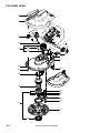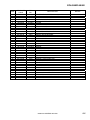
1
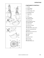
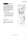
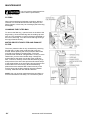
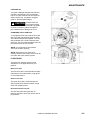
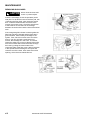
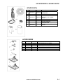
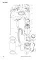
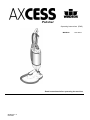
Polisher
Operating Instructions (ENG)
MODELS:
1.012-063.0
Read instructions before operating the machine.
86324160 - A
03/23/09
MACHINE DATA LOG
2
86324160 AXCESS 03/23/09
TABLE OF CONTENTS
Machine Data Log/Overview........................... 2
Table of Contents............................................ 3
PARTS LIST
Accessories & Spare Parts..............................5-1
Vacuum ...........................................................5-2
Polisher Head..................................................5-4
HOW TO USE THIS MANUAL
How to use this Manual................................... 1-1
SAFETY
Important Safety Instructions .......................... 2-1
Hazard Intensity Level..................................... 2-2
Grounding Instructions .................................... 2-3
OPERATIONS
Technical Specifications.................................. 3-1
How This Machine Works ............................... 3-1
Components/Controls ..................................... 3-2
Assembly......................................................... 3-3
Operating Instructions. .................................... 3-3
Indicator Light.................................................. 3-4
Floor Preparation ............................................ 3-4
MAINTENANCE
Filters............................................................... 4-1
Filter/Bag Replacement................................... 4-1
Motor Protection Filter..................................... 4-1
LED-Display .................................................... 4-2
Changing the Floor Pad .................................. 4-2
Floor Pads ....................................................... 4-2
Removing Blockages ...................................... 4-3
86324160 AXCESS 03/23/09
3
HOW TO USE THIS MANUAL
This manual contains the following sections:
-
HOW TO USE THIS MANUAL
SAFETY
OPERATIONS
MAINTENANCE
PARTS LIST
The HOW TO USE THIS MANUAL section will tell
you how to find important information for ordering
correct repair parts.
Parts may be ordered from authorized Windsor
dealers. When placing an order for parts, the
machine model and machine serial number are
important. Refer to the MACHINE DATA log which
is filled out during the installation of your machine.
The MACHINE DATA log is located on the inside
of the front cover of this manual.
The SAFETY section contains important
information regarding hazard or unsafe practices
of the machine. Levels of hazards is identified that
could result in product or personal injury, or severe
injury resulting in death.
The OPERATIONS section is to familiarize the
operator with the operation and function of the
machine.
The MAINTENANCE section contains preventive
maintenance to keep the machine and its
components in good working condition. They are
listed in this general order:
-
The PARTS LIST section contains assembled
parts illustrations and corresponding parts list. The
parts lists include a number of columns of
information:
-
The model and serial number of your machine is
on the bottom back-end of the machine.
Filters
Blockages
-
-
REF – column refers to the reference
number on the parts illustration.
PART NO. – column lists the part
number for the part.
PRV NO. - reference number.
QTY – column lists the quantity of the
part used in that area of the machine.
DESCRIPTION – column is a brief
description of the part.
SERIAL NO. FROM – column
indicates the first machine the part
number is applicable to. When the
machine design has changed, this
column will indicate serial number of
applicable machine. The main
illustration shows the most current
design of the machine. The boxed
illustrations show older designs. If
column has an asterisk (*), call
manufacturer for serial number.
NOTES – column for information not
noted by the other columns.
NOTE: If a service or option kit is installed on your
machine, be sure to keep the KIT INSTRUCTIONS
which came with the kit. It contains replacement
parts numbers needed for ordering future parts.
NOTE: The number on the lower left corner of the
front cover is the part number for this manual.
1-1
86324160 AXCESS 03/23/09
SAFETY
IMPORTANT SAFETY INSTRUCTIONS
When using an electrical appliance, basic precaution
must always be followed, including the following:
READ ALL INSTRUCTIONS BEFORE USING THIS MACHINE.
To reduce the risk of fire, electric shock, or injury: Use only indoors. Do not use outdoors or expose to
rain.
Use only as described in this manual. Use only manufacturer’s recommended components and attachments.
If the machine is not working properly, has been dropped, damaged, left outdoors, or dropped into water,
return it to an authorized service center.
Do not operate the machine with any openings blocked. Keep openings free of debris that may reduce
airflow.
Machine can cause a fire when operating near flammable vapors or materials. Do not operate this machine
near flammable fluids, dust or vapors.
For cleaning dry hard floors only. Do not use on wet floor.
Do not expose the machine to liquid, moisture or heat.
Do not touch the floor pad or drive while the machine is running.
Do not use machine without floor pad.
Do not use outdoors or on inappropriate surfaces, e.g stone or concrete.
Before using machine, remove all sharp and abrasive materials (i.e. grit and sand) with a vacuum cleaner.
This machine is suitable for commercial use, for example in hotels, schools, hospitals, factories, shops and
offices for more than normal housekeeping purposes.
Maintenance and repairs must be done by qualified personnel.
During operation, attention shall be paid to other persons, especially children.
The machine shall only be operated by instructed and authorized persons.
When leaving unattended, unplug the machine.
Do not handle the plug or machine with wet hands.
Do not unplug machine by pulling on cord. To unplug, grasp the plug, not the cord.
Do not use with damaged cord or plug. Follow all instructions in this manual concerning grounding the
machine.
Do not pull or carry by cord, use cord as a handle, close a door on cord, or pull cord around sharp edges or
corners.
Do not pull/run machine over cord. Keep cord away from heated surfaces.
Connect to a properly grounded outlet. See Grounding Instructions.
SAVE THESE INSTRUCTIONS
86324160 AXCESS 03/23/09
2-1
SAFTEY
The following symbols are used throughout this guide as indicated in their descriptions:
HAZARD INTENSITY LEVEL
There are three levels of hazard intensity identified by signal words - WARNING and CAUTION and FOR
SAFETY. The level of hazard intensity is determined by the following definitions:
! WARNING
WARNING - Hazards or unsafe practices, which COULD result in severe personal injury or death.
! CAUTION
CAUTION - Hazards or unsafe practices, which could result in minor personal injury or product or property
damage.
FOR SAFETY: To Identify actions, which must be followed for safe operation of equipment.
Report machine damage or faulty operation immediately. Do not use the machine if it is not in proper operating
condition. Following is information that signals some potentially dangerous conditions to the operator or the
equipment. Read this information carefully. Know when these conditions can exist. Locate all safety devices on
the machine. Please take the necessary steps to train the machine operating personnel.
FOR SAFETY:
DO NOT OPERATE MACHINE:
Unless trained and authorized.
Unless operation guide is read and understood.
In flammable or explosive areas.
In areas with possible falling objects.
WHEN SERVICING MACHINE:
Avoid moving parts. Do not wear loose clothing; jackets, shirts, or sleeves when working on the machine. Use
Windsor/manufacturer approved replacement parts.
2-2
86324160 AXCESS 03/23/09
SAFETY
GROUNDING INSTRUCTIONS
This appliance must be grounded. If it should malfunction or breakdown, grounding provides a path of least
resistance for electric current to reduce the risk of electric shock. This appliance is equipped with a code
having an equipment–grounding conductor and grounding plug. The plug must be inserted into an
appropriate outlet that is properly installed and grounded in accordance with all local codes and ordinances.
WARNING
Improper connection of the equipment-grounding conductor can result in a risk of electric shock. Check with a
qualified electrician or service person if you are in doubt as to whether the outlet is properly grounded. Do not
modify the plug provided with the appliance – if it will not fit the outlet, have a proper outlet installed by a
qualified electrician.
This appliance is for use on a nominal 120-volt circuit, and has a grounded plug that looks like the plug
illustrated in sketch A. A temporary adaptor looks like adaptor illustrated in sketches B and C, may be used it
connect this plug to a 2-pole receptacle as shown in sketch B if a properly grounded outlet is not available.
The temporary adaptor should be used only until a properly grounded outlet (sketch A) can be installed by a
qualified electrician. The green colored rigid ear, lug or the like extending from the adaptor must be
connected to a permanent ground such as a properly grounded outlet box cover. Whenever the adaptor is
used, it must be held in place by a metal screw.
Note: In Canada, the use of a temporary adaptor is not permitted by the Canadian Electrical Code.
GROUNDED
OUTLET BOX
GROUNDED
OUTLET
ADAPTER
TAB FOR
GROUNDING SCREW
METAL SCREW
GROUNDING
PIN
(A)
(B)
86324160 AXCESS 03/23/09
(C)
2-3
OPERATIONS
TECHNICAL SPECIFICATIONS
VACUUM PORTION: (Carry unit)
ITEM
Vacuum Motor
Vacuum Motor Rated Power
Vacuum Motor Maximum Power
Suction
Air Flow
Filter Bag Capacity
Weight
Without power head
With power head
Dimensions - Height
Housing
Cable
DIMENSION/CAPACITY
High Performance, single stage
1000 Watts
1300 Watts
225 Mbar (2300 mm WS)
106 cfm (50 l/s)
3.5 liters, 3 layer, enclosed, top-loading
9.9 (4.5 kg)
18.5 lbs (8.4 kg)
48 in (123 cm)
Injection molded, high impact ABS and PP plastic
31 ft (9.5 M) 18/3 SJT
POWER HEAD: (Detachable Head)
ITEM
Motor
Speed
Floor pad diameter
Protection
DIMENSION/CAPACITY
200 Watts
2000 rpm
11.50 inches (294 mm)
Grounded
HOW THIS MACHINE WORKS
The high speed of the polisher pad causes the ingredients in the floor maintainer to bond together and form a
layer. In this way you achieve a high gloss shine and create a new surface which protects the flooring.
NOTE: All repairs should be performed by an authorized service representative.
3-1
86324160 AXCESS 03/23/09
OPERATIONS
COMPONENTS/CONTROLS
1. Handle
2. On/Off Switch
3. Handle Tube
4. Power Supply Cable
5. Dust Bag Housing
6. Filter Cover
7. Cable Hook
8. Hose
9. Hose Handle
10. Carrying Handle
11. Exhaust Filter
12. Filter Retaining Rings
13. Release Button
14. Swivel Neck
15. UHS floor polisher
16. Foot Pedal
17. LED-operation light (green)
18. LED-overload light (red)
19. Bumper
20. Suction duct access cover
21. Release button
22. Castor
23. Seal
24. Support castor
25. Floor Pad
26. Pad retainer
27. Quick-release disc
86324160 AXCESS 03/23/09
3-2
OPERATIONS
ASSEMBLY
! CAUTION
Please read all instructions
before using this machine.
1. To assemble, carefully attach the polisher
nozzle to the vacuum cleaner through the
fitting at the bottom of the vacuum until it
locks.
2. Push the black end of the hose into the
connection on the filter cover.
3. Insert the hose handle into the suction opening
on the side and press the hose into its place
on the side of the machine.
4. Fit the Floor Pad into the recesses of the pad
retainer located underneath the polisher head.
5. Push the Floor Pad down with one hand
against the resistance of the four spring
loaded ejector pins.
6. Fit the Quick-release disc with the other hand
and turn it clockwise until the lever arms click
into the floor pad.
7. The Quick-release disc is fitted correctly when
its lines and the lines on the floor pad coincide.
OPERATING INSTRUCTIONS
NOTE: Use this Polisher according to the following
instructions.
This Polisher is recommended for the optimal
cleaning of your high-quality, water resistant hard
floors. The rotating design of the swivel neck
allows the suction-polisher to move in any
direction.
1. Ensure that the on / off switch of your Polisher
is in the off position.
2. Release the vacuum cleaner cable completely
and plug it into the wall outlet. Now you can
start the machine by pressing the on / off
switch. This Polisher has a soft-start system
so there may be a slight delay before it
operates.
3. To start, push the foot pedal of the floor
polisher and lower the telescopic tube or
respectively the vacuum cleaner. Failure to
use the foot pedal will cause lasting damage to
the machine. The food pedal locks the swivel
neck in an upright position. In this position the
Polisher automatically turns off. The swivel
neck has an internal lock which will hold the
machine in the central position to avoid
unwanted rotation.
! CAUTION
After using the polisher hold
the polisher until the floor
pad stops rotating.
3-3
86324160 AXCESS 03/23/09
OPERATIONS
When using the hose and
attachments, keep the
machine in the upright positions.
! CAUTION
The hose handle can be removed from the side of
the vacuum and can be used with or without
attachments. Maintain a grasp on the machine
when using the hose as it can tip if the hose is
pulled too far. The machine can also be used
without a power head or other floor tool. You can
easily carry the machine by using the carrying
handle. When you have finished using the
machine, turn it off by moving the on/off switch into
the off position. Then unplug the cable and wind it
onto the cable hook and handle
FLOOR PREPARATION
1. First, clean your floor with a vacuum cleaner.
Afterwards clean the floor with a detergent
cleaner as per the manufacturers instructions.
2. Once dry, polish the floor with the green Floor
Pad. It is recommended to move the floor
polisher slowly over the floor in a regular
motion and to go in different directions for best
results.
INDICATOR LIGHTS
The green LED light indicates that the polisher is
operational.
The red LED light comes on if the machine has
shut down for safety reasons, for example,
overload or clogging. (See Removing Blockage
section.)
86324160 AXCESS 03/23/09
3-4
MAINTENANCE
! CAUTION
Use only genuine replacement floor
pads to ensure performance,
longevity and safety.
FILTERS
When the orange bag full indicator is showing, airflow is
reduced. This could be because the filter bag is full, the
filters clogged, or there may be a blockage (see Removing
blockages).
CHANGING THE FILTER BAG
To remove the filter bag , open the latch on the side of the
bag housing. Close the filter bag with the sealing cap and
lift it out. The procedure to replace the bag is illustrated on
the front of each bag. You cannot close the bag housing if
the bag is fitted incorrectly.
MOTOR PROTECTION FILTER AND EXHAUST
FILTER
The motor protection filter is only accessible by removing
the filter bag. Lift the motor protection filter up by the
bracket. When replacing the motor protection filter make
sure that it is pressed in position tightly. The motor
protection filter should be changed when it is dirty or at the
latest when you have used 20 filter bags. Change the
exhaust filter at the same time as the motor protection
filter. To do this, carefully remove the filter retaining rings
and put them to the side. Next pull the enforcement strips
of the exhaust filter out of the housing slot and remove the
exhaust filter from the housing. When reassembling,
please ensure the exhaust filter is fitted correctly in the
housing slots and the filter retaining rings are installed
correctly. Otherwise the filter will be ineffective.
NOTE: Use only genuine replacement bags and filters to
ensure effectiveness and safety. Do not wash any filters.
4-1
86324160 AXCESS 03/23/09
MAINTENANCE
LED-DISPLAY
The green LED light indicates that the floor
polisher is operational. The red LED light
comes on if the machine has shut down for
safety reasons e.g. overload or clogging
(refer to “Removing Blockages).
Please check the
Floor Pad regularly
for sharp and abrasive materials e.g. grains
of sand. If necessary please change the
pad, otherwise floor damage can occur.
! CAUTION
CHANGING THE FLOOR PAD
To change the Floor Pad, hold the floor pad
with one hand and squeeze the lever arms
of the Quick-release disc together. Turn the
Quick-release disc counter-clockwise and
remove it. The floor pad will release from the
pad retainer and can be removed.
NOTE: The underside of the machine
should be cleaned regularly.
NOTE: New design Floor Pads fit all
models, however olds design Floor Pads will
not fit the new quick-release system.
FLOOR PADS
There are four different cleaning pads
available to cover applications for your
polisher.
Blue Floor Pad
The blue floor pad is recommended for daily
maintenance and will maintain a high gloss
on soft coated floors.
Green Floor Pad
The green floor pad is recommended for
daily maintenance and will maintain a high
shine with a hard surface.
Red and Yellow Floor pad
The red and yellow floor pads are for
restoring a shine to worn floor which have a
hard surface.
86324160 AXCESS 03/23/09
4-2
MAINTENANCE
REMOVING BLOCKAGES
! CAUTION
Never clean the hose with
a stick or pointed object.
If there is a blockage, check the pad area (under
side) first. To do this first remove the floor pad, see
“Changing the Floor Pad”. Also check the suction
duct . Push the release button and remove the
suction duct access cover. Check the swivel neck
of the Polisher. Ensure there is no blockage
between the suction duct and the inlet of the swivel
neck.
If the orange bag full indicator is showing after the
filter bag has been changed and the filters are in
good condition, there is likely a blockage in the
system. First, check for suction at the end of the
hose. If you can only feel a small amount of
suction, the blockage is in the hose. To unblock,
loosen the safety ring on the lid. Remove the hose
from the machine and reverse the airflow through
the hose by putting the hose handle in the
connecting tube of the filter cover. Stretch the hose
in the spot where the blockage is and open and
close the end of the hose. Also check the suction
opening, which the hose handle fits into.
4-3
86324160 AXCESS 03/23/09
ACCESSORIES & SPARE PARTS
SPARE PARTS
Ref
Part No.
Prv. No.
1A
86320520
3230WI30
1B
86312140
3230WI00
1C
86320530
3286WI40
2
3
86309330
86284790
7029WI
4
86284770
7012
5
86323990
-
Description
DIAMOND PAD GREEN FINE
ABRASION
BLUE FLOOR PAD
DIAMOND PADS
RED/YELLOW COMBO
PACK
FILTER, EXHAUST
FILTER BAG
FILTER, MOTOR
PROTECTION
AXCESS POLISHER POWER
HEAD
ACCESSORIES
Ref
1
2
3
4
5
6
Part No.
86138400
86146290
86322440
86322450
86324000
86324010
Prv. No.
1094DG
1491DG
1081DG
1092DG
-
Description
DUSTING BRUSH, DK GRAY
UPHOLSTERY NOZZLE, DK GRY
CLIPS, ATTACHMENT, DK GRAY
CREVICE TOOL, DK GRY
POWER HEAD 12”
POWER HEAD 15”
86324160 AXCESS 03/23/09
5-1
VACUUM
5-2
86324160 AXCESS 03/23/09
VACUUM
POS.
1
2
3
4
5
6
7
8
9
10
11
12
13
14
15
16
17
18
19
20
21
22
23
24
25
26
27
28
29
30
31
32
33
34
35
36
37
38
39
40
41
PRODUCT
CODE
86137750
86146820
86142920
86144780
86146510
86139960
86145180
86146380
86144740
86143660
86138380
86141270
86324770
86142510
86144830
86146830
86146490
86146500
86142680
86139340
86309310
86144790
86284790
86309320
86309330
86141460
86309340
86146250
86142520
86139350
86145140
86142500
86145480
86142670
86139110
86016900
86292570
86141670
86144630
86309880
86324820
PRV
NO.
7135DG
7065
7096
01016ER
7057HG
7102ER
7098
1047
7009
7041ER
05140S
7001
7012
7080ER
0127ER
7068ER
7025
7090HG
7027HG
01017ER
7029WI
7017 HG
7076HG
7163HG
7126BL
7035BL
7073HG
05138
7050SB
1030UL
0103ER
1035HG
7094ER
7018OR
7142
7024
DESCRIPTION
NOTES:
AIR DUCT
INTERNAL WIRING ET
INTERNAL CABLE
SCR, 4X16-T20 STS
VALVE COVER
PRINTED CIRCUIT BOARD 120V
SOUND INSULATION
VAC MOTOR SEAL
RUBBER MOUNTING
VAC MOTOR 120V
CARBON BRUSH SET
DUST BAG HOUSING
FILTER, MOTOR PROTECTION
HANDLE TUBE
SCR M 4X10
INTERNAL WIRING
VALVE DISC
VAVLE SPRING
HOSE DUCT
CABLE HOOK
COVER, DUST BAG HOUSING HG
SCR, 4X20-T20 STS
FILTER BAG
FILTER COVER HG
EXHAUST FILTER HG
EXHAUST FILTER CLAMP
LOWER HOUSING HG
TUBE PLUG
HANDLE GRIP CPL
CABLE 120V, US
SLIDING BUTTON
HANDLE FRAME
ROCKER SWITCH, 2 POL.
HOSE DUCT
CABLE CLAMP
SCREW C 3,9X16
CABLE GROMMET
FILTER INDICATOR, CPL.
RETAINING RING, CPL.
PROTECTION FILM
SPRING LATCH FILTER COVER
86324160 AXECSS 03/23/09
5-3
POLISHER HEAD
2
1
4
8
9
5
11
12
10
3
7
6
13
21
5
14
16
17
18
19
20
23
15
22
24
27
25
28
26
20
29
34
20
31
30
32
20
35
33
36
5-4
86324160 AXCESS 03/23/09
POLISHER HEAD
POS.
1
2
3
4
5
6
7
8
9
10
11
12
13
14
15
16
17
18
19
20
21
22
23
24
25
26
27
28
29
30
31
32
33
34
35
36
PRODUCT
CODE
86314610
86314360
86314370
86314380
86314390
86324850
86144990
86324860
86324870
86324880
86324890
86144820
86138140
86314450
86314460
86314470
86314480
86138390
86314490
86144780
86314500
86314510
86321410
86141710
86314520
86314530
86147030
86314540
86314550
86314560
86314570
86314580
86312140
86320520
86320530
86314590
86320540
86321420
PRV
NO.
3204WI
3205TG
3258DG
3227DG
3249
2947DG
2950ER
1737DG
2952DG
2945DG
2951DG
01027ER
2954
3257ER
3238
2938ER
3252ER
05141S
3222
01016ER
3245
3242ER
01029ER
2937OR
3201DG
3254DG
0102
3268ER
3221
3220ER
01033ER
3202DG
3230WI00
3230WI30
3286WI40
3219
3281NE
3280
DESCRIPTION
NOTES
POWER HEAD COVER
SUCTION DUCT ACCESS COVER
SWIVEL NECK SUPPORT
TURNING SWIVEL NECK
WIRING SWIVEL NECK
COVER
BEARING SEGMENTS
RELEASE BUTTON
BUTTON COVER
SWIVEL NECK SLIDE
SOCKET COVER, TS-NECK
SCREW F 3,9X9,5 DIN7981
SWIVEL NECK BEARING
SWIVEL NECK SUPPORT L.H.
SWITCH LEVER
AXLE HSB
MOTOR 120V CPL HSB
PAIR OF CARBON BRUSHES
MOTOR PULLEY HSB
SCREW
INTERNAL CABLE
PRINTED CIRCUIT BOARD 120V
SCREW C 2,9X13
FOOT PEDAL
CHASSIS HSB
REAR CASTOR
SCREW F 3,9X13 DIN 7981
SEALING STRIP
DRIVE BELT HSB
CENTER CASTOR
SCREW, M10X25 DIN 7991
BELT DRIVE COVER
BLUE FLOOR PAD
DIAMOND PAD GREEN FINE ABRASION
DIAMOND PADS RED/YELLOW COMBO PACK
SEAL HSB
BURNISHER PAD RETROFIT KIT
PAD HOLDER QUICK RELEASE
86324160 AXCESS 03/23/09
5-5
NOTES:
5-6
86324160 AXCESS 03/23/09