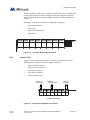
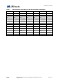
1
TX3 Series
TX3-CX CARD ACCESS SYSTEM
Installation and Operation Manual
Version 2.2
LT-980
Mircom
Copyright 2015
1 (61)
Copyright 2015 Mircom Inc.
All rights reserved.
Mircom TX3-CX Card Access System Installation and Operation Manual v.2.1
This manual, as well as the software described in it, is provided under licence or other agreements
and may be used or copied only in accordance with the terms of such license. The content of this
manual is furnished for informational use only. It is subject to change without notice, and should not
be construed as a commitment by Mircom. Mircom assumes no responsibility or liability for any errors
or inaccuracies that appear in this book.
Except as permitted by such license, no part of this publication may be reproduced, stored in a
retrieval system, transmitted in any form by means electronic, mechanical, using any recorded
media, or any other format without the prior written permission of Mircom.
Mircom
25 Interchange Way
Vaughan, Ontario
L4K 5W3
905.660.4655
Fax:905.660.4113
2 (61)
Version 2.2
Copyright 2015
Table of Contents
Table of Contents
1
Welcome 7
1.1
1.2
1.2.1
1.2.2
1.3
1.3.1
1.4
1.4.1
1.5
1.6
1.6.1
1.6.2
1.6.3
1.7
1.7.1
1.7.2
1.7.3
1.7.4
1.7.5
Introducing the TX3-CX Card Access System 8
Applications 8
Wiegand interface 8
Card Access System 9
Configurable Features 9
PC Configurator Software 9
Installer Responsibilities 10
PC Requirements 10
Network Setup 10
About This Manual 13
Version Control 13
Additional Documentation 14
Key Terms 14
Contact Us 14
General Inquiries 15
Customer Service 15
Website 15
Email 15
Technical Support 15
2
Configurable Features 17
2.1
2.1.1
2.1.2
2.2
2.2.1
2.2.2
2.2.3
2.2.4
2.2.5
2.2.6
2.2.7
2.3
2.3.1
2.3.2
2.3.3
2.3.4
2.3.5
2.3.6
2.3.7
2.3.8
2.3.9
2.3.10
2.3.11
2.3.12
Inputs 18
Request to exit for reader A or B 18
Door sense for reader A or B 18
Correlation 19
Assigning events to access points 19
Events 19
Actions 19
Panels 20
Output 20
Duration 20
Schedule 20
Access Criteria 20
Lock / Unlock 21
High security 22
PC decision required 22
Facility code mode 22
Card + PIN 23
Anti-passback 23
Temporary card 23
Interlock 23
Access level 23
Controller options 24
Access point options 24
Card options 26
Version 2.2
LT-980
TX3-CX Card Access System Installation and Operation Manual
Copyright 2015
3 (61)
4 (61)
LT-980
2.4
2.4.1
2.4.2
2.4.3
2.4.4
2.4.5
2.4.6
2.5
2.6
2.7
2.7.1
2.7.2
Timers 27
Timer schedule 27
Unlock time 27
Extended unlock time 27
Anti-passback 27
Door held open warning 28
Door held open alarm 28
Schedules 28
Holidays 29
System Status 29
Common trouble 29
Common alarm 29
3
Installation and Setup 31
3.1
3.2
3.2.1
3.2.2
3.2.3
3.2.4
3.2.5
3.2.6
3.2.7
3.3
3.3.1
3.3.2
3.3.3
3.3.4
3.3.5
3.3.6
3.4
3.4.1
3.4.2
3.4.3
3.4.4
3.4.5
3.4.6
3.4.7
3.5
3.5.1
3.5.2
3.5.3
3.5.4
3.6
3.6.1
3.6.2
3.6.3
3.6.4
3.7
3.8
Grounding the Card Access System 32
Installing the Controller and Components 32
Optional Components 32
Installing the Card Access Controller 33
Installing the thermal kit 33
Installing the tamper switch 33
Installing the modem 33
Installing the IP Module 34
Installing the MD-993 module 35
Controller Board Description 36
Controller Panel LEDs 36
Controller Board Components 36
Power Supply 38
ON/OFF Switch and Battery Back-up 38
RS-485 39
USB Port 39
Connecting the Inputs 39
Inputs 1 to 8 40
Request to Exit 41
Door sense 41
General purpose input 41
Active state 41
Supervision requirement 41
Alarm Delay 43
Connecting the Outputs 43
Specific functions 43
Active state 44
Outputs 1 to 6 44
Outputs 7 and 8 45
Connecting the Card Reader 45
Card Reader Requirements 45
Card Reader Connection 46
Card Reader Status LEDs 47
Card Reader Beeper 47
Setting DIP Switches SW2 47
Setting Jumpers 51
TX3-CX Card Access System Installation and Operation Manual
Copyright 2015
Version 2.2
3.9
3.9.1
3.10
3.10.1
3.11
Turning on the Controller 52
Default Configuration Values 52
Updating Firmware 52
Firmware Version Control 53
Beginning Configuration 53
Warranty & Warning Information 55
Special Notices 58
Version 2.2
LT-980
TX3-CX Card Access System Installation and Operation Manual
Copyright 2015
5 (61)
List of Figures
Figure 1
Basic Card Access System 10
Figure 2
Card Access System using an RS-485 network 11
Figure 3
Card Access System using an ethernet TCP/IP network. Controllers connected
to an ethernet network are Master Nodes. 11
Figure 4
Card Access System using both ethernet and RS-485 networks 12
Figure 5
Controller Back Cover Dimensions and Optional Component Location 32
Figure 6
Modem Board Location 34
Figure 7
IP Module Board Location 35
Figure 8
MD-993 Module 35
Figure 9
Controller Board Connection Locations 37
Figure 10
Power Supply 38
Figure 11
Controller Board Battery Wiring 38
Figure 12
RS-485 Connections 39
Figure 13
Controller Board Input Terminals 40
Figure 14
Input Terminal Sample Connections 40
Figure 15
Input - Supervised for Open 42
Figure 16
Input - Supervised for Short 42
Figure 17
Input - Supervised for Open and Short 43
Figure 18
Controller Output Terminal Sample Connections 44
Figure 19
Outputs 7 and 8 Sample Connections 45
Figure 20
Card Reader Connections 46
Figure 21
Controller Board Card Reader Connectors 46
Figure 22
Location of Jumpers JW1 to JW5 and Switches SW1 and SW2 51
6 (61)
LT-980
TX3-CX Card Access System Installation and Operation Manual
Copyright 2015
Version 2.2
1
Welcome
This manual provides information about the installation and operation of the
TX3-CX Card Access System, and must be read in its entirety before beginning
any installation work.
Installation must be performed by a qualified technician and must adhere to the
standards and special notices set by the local regulatory bodies.
Note:
Mircom periodically updates panel firmware and Configurator
Software to add features and correct any minor inconsistencies.
For information about the latest firmware or software visit the
Mircom website at www.mircom.com.
For warranty and special notices information see the Warranty and Special
Notices chapter on page 55.
Warning:
The Card Access System must be grounded by a qualified
electrician. An improperly grounded unit can result in
equipment malfunction and electrical shock.
This chapter explains
Version 2.2
LT-980
•
The TX3-CX Card Access System
•
Applications
•
Configurable Features
•
Installer Responsibilities
•
Setup
TX3-CX Card Access System Installation and Operation Manual
Copyright 2015
7 (61)
Welcome
1.1
Introducing the TX3-CX Card Access System
The TX3-CX Card Access System is part of the Mircom suite of products that
provide building ready monitoring, control and integrated security solutions for
use in the high end multi-tenant residential market.
The Card Access System addresses the need within today’s high end multi-tenant
residential market for an easy-to-use tenant access system and an easy-to-use
configuration utility.
This manual provides the technician with information about the installation and
configuration of the Card Access System and explains how to configure various
components for a new system, including the modification of an existing system.
1.2
Applications
Mircom's Card Access System consists of a controller, two card readers and
configuration software. The controller can accept at the same time, a
combination of card readers with the 26-bit Wiegand, 35-bit Indala, 37-bit
Mircom, 50-bit RBH, and 32-bit CSN card reader standards to control two access
points or doors. The Card Access System can set elevator usage if elevator
controls are used.
A number of different card readers are supported, such as the TX3-CX-REC
Wiegand wireless receiver, all of which are configurable using the configurator
software.
The Card Access System can be used in a stand-alone or networked environment
using a standard RS-485, daisy chain peer-to-peer network arrangement.
This network can consist of only the Card Access Controller or a combination of
Touch Screens, Lobby Control Units, Elevator Restriction Units and Card
Access Units. Up to 63 units can be networked on any RS-485 network or
subnetwork. Valid RS-485 network addresses range from 1 to 63. One of the
networked units with a real time clock, such as Touch Screen, Lobby Control or
Card Access must have their network address set to 1.
If an ethernet network is used, you can connect more than 63 units to your system.
If you use an etherent network with RS-485 subnetworks, each RS-485
subnetwork can have 63 devices connected to it.
1.2.1
Wiegand interface
The Wiegand interface is a wiring standard for card readers for establishing the
connections between a card reader and the Card Access System. This interface is
a serial interface requiring 7 to 10 conductors for communications between the
reader and the controller. This interface also supplies 12V power to the reader.
8 (61)
LT-980
TX3-CX Card Access System Installation and Operation Manual
Copyright 2015
Version 2.2
Welcome
The Wiegand compatible access card has 26 bits of information embedded onto
the card. The card reader reads and registers the card information and sends it
back to the controller in a serial bit stream.
1.2.2
Card Access System
The Mircom Card Access System supports a proprietary 37-bit encoding
technology and a 26-bit SIA standard format, and consists of a maximum of 63
Card Access Controllers networked together. Each Card Access Controller can
have two card readers. The Card Access System provides an optional battery
backup and a real time clock.
The Card Access System integrates with the TX3 Telephone Access system by
utilizing a common network for both Telephone Access and Card Access
Systems.
A PC provides configuration and on-line monitoring of the Card Access System
and the Telephone Access System status. Once the system is configured, the PC
is not required.
1.3
Configurable Features
The system is configured by connecting the inputs and outputs to device access
points, and using the configurator software to establish the correlations between
these inputs and outputs.
Additional physical configuration is required using the dip switches and jumpers
on the controller. DIP switches set the Card Access Controller network address.
Jumper settings set the controller for firmware updates.
1.3.1
PC Configurator Software
The Configurator Software TX3-MSW is a combined Telephone Access System
and Card Access System configurator that uses a common database. Once the
controller is installed the system applies its default values. Use the configurator
software to fully configure the system. See the following documentation:
Version 2.2
LT-980
•
LT-995 Configuration and Administration Guide
•
LT-973 TX3 Software Guide
TX3-CX Card Access System Installation and Operation Manual
Copyright 2015
9 (61)
Welcome
1.4
Installer Responsibilities
The installation and setup must be done by a qualified technician. The technician
is responsible for installing all of the system components, connecting all of the
input and output wiring for the appropriate door entry systems, and ensuring that
the wiring adheres to the requirements of the system for proper operation using
the configurator software.
1.4.1
PC Requirements
The following are the PC requirements:
1.5
•
Dual core processor
•
1.8 GHz, 1 GB RAM
•
Windows XP or later
•
USB Connection
Network Setup
The Card Access System can consist of either stand-alone Card Access
Controllers or networked Card Access Controllers. Networked Card Access
Controllers can communicate over an RS-485 network, an ethernet TCP/IP
network, or a combination of an ethernet network with RS-485 subnetworks. All
Card Access Controllers can communicate over RS-485. To communicate over
an ethernet network you need at least one IP-enabled Card Access Controller
(called a Master Node).
The TX3 Configurator software can connect to any of these network
configurations. How you connect to the network (that is, through TCP/IP, USB,
a modem, or the COM port) determines what devices you can configure on the
network using the TX3 Configurator. The different network configurations are
explained in the rest of this section.
Figure 1 shows a basic Card Access System with one Card Access Controller and
two card readers. The maximum distance between the Card Access Controller
and the card readers is 500 feet.
Card Reader A
Card Reader B
Card Access Controller
Figure 1.
10 (61)
LT-980
Basic Card Access System
TX3-CX Card Access System Installation and Operation Manual
Copyright 2015
Version 2.2
Welcome
Figure 2 shows a network with two Card Access Controllers connected to an RS485 network. The Card Access System can have up to 63 Card Access Controllers
networked together. If you connect to any device on the RS-485 network (using
USB, a modem, or a COM port), you can also connect to and configure any other
device on the RS-485 network using the TX3 Configurator software.
Card Access Controller
Card Access Controller
Card Reader A
Card Reader A
Card Reader B
Card Reader B
RS-485 Network
Figure 2.
Card Access System using an RS-485 network
Figure 3 shows a configuration with Card Access Controllers connected to an
ethernet TCP/IP network. This configuration removes the 63 device limitation
that you have on an RS-485 network. The devices connected to an ethernet TCP/
IP network are called Master Nodes. If you connect to the TCP/IP network with
the TX3 Configurator, you can connect to and configure any of the Master Nodes
on the ethernet TCP/IP network. If you connect directly to one of the Master
Nodes using USB, a modem, or a COM port, you will be able to configure that
device but not any other device.
Card Access Controller
(Master Node)
Card Access Controller
(Master Node)
Card Reader A
Card Reader A
Card Reader B
Card Reader B
Ethernet Network
Figure 3.
Version 2.2
LT-980
Card Access System using an ethernet TCP/IP network.
Controllers connected to an ethernet network are Master
Nodes.
TX3-CX Card Access System Installation and Operation Manual
Copyright 2015
11 (61)
Welcome
Notes:
In order for a panel to be a Master Node it must satisfy the following
conditions.
•
It must be IP capable. Panels that are IP capable are usually
denoted by a “-A” at the end of their model names.
•
If the panel is not a Touch Screen, it must have a TX3-IP IP
Module installed.
Figure 4 shows a Card Access System using an ethernet network with RS-485
subnetworks. The Card Access Controllers connecting to to a Master Node’s
RS-485 subnetwork are Slave Nodes to the Master Node. Each RS-485
subnetwork can have up to 63 controllers connected to it; you can still have more
than 63 Master Nodes connected to the ethernet network.
Card Access Controller
(Master Node)
Card Reader A
Card Access Controller
(Slave Node)
Card Reader B
Card Reader A
Card Reader B
RS-485 Subnetwork
Ethernet Network
Card Access Controller
(Master Node)
Card Reader A
Card Access Controller
(Slave Node)
Card Reader B
Card Reader A
Card Reader B
RS-485 Subnetwork
Figure 4.
12 (61)
LT-980
Card Access System using both ethernet and RS-485
networks
TX3-CX Card Access System Installation and Operation Manual
Copyright 2015
Version 2.2
Welcome
If you connect to the ethernet TCP/IP network with the TX3 Configurator, you
can configure any of the nodes in the system. If you connect direcly to a controller
using USB, a modem, or a COM port, you will only be able to configure devices
that are on the same RS-485 subnetwork as that device.
Note:
1.6
There can only be one Master Node on an RS-485 subnetwork. That
is, you cannot connect one RS-485 subnetwork to another RS-485
subnetwork. However, if you want to connect to a Touch Screen
panel remotely over the Internet (for instance, to configure Touch
Screen options such as color and themes), the Touch Screen panel
must be set as an Master Node even if there is no slave panel
connected to it.
About This Manual
This manual provides comprehensive information on the installation and
configuration of the Card Access System by the installation technician. Tasks are
described in the order that they are likely to be performed.
Chapter 2 describes the installation of the controller.
Chapter 3 describes the configurable modes of operation.
This manual applies to the following models:
1.6.1
•
TX3-CX-2K-A IP Capable Two Door Card Access Controller Kit
•
TX3-CX-2-A IP Capable Two Door Card Access Controller
Version Control
The version number appears on the front cover and changes whenever there is a
major or minor update to any part of the system regarding operation or
configuration.
The following convention indicates major or minor changes:
Initial release. Version 1.00.0
Major change. Version 2.00.0
Minor change. Version 2.01.0
Pre-release changes. Version 2.01.1
Version 2.2
LT-980
TX3-CX Card Access System Installation and Operation Manual
Copyright 2015
13 (61)
Welcome
1.6.2
Additional Documentation
For additional documentation, see the following Mircom literature:
1.6.3
•
TX3 Telephone/Card Access System Installation and Operation Manual
LT-969
•
TX3 Telephone Access System User’s Guide LT-968
•
TX3 MDM Modem Module Installation LT-971
•
TX3-IP IP Module Installation Instructions LT-1161
•
TX3 Two Door Card Access System Kit Catalogue Number 6531
•
TX3 Series Elevator Restriction Accessories Catalogue Number 6532
•
TX3 Configuration and Administration Manual LT-995
•
TX3 Configurator Quick Start LT-973
•
TX3-USB-AD Kit Installation Instructions LT-6027
Key Terms
The following terms are common and specific to this manual:
CAU. Card Access Unit
ERU. Elevator Restriction Unit
LCU. Lobby Control Unit
1.7
Contact Us
Mircom fosters a collaborative support process and environment in providing
early feedback to meet your specific needs.
You can contact us from Monday to Friday 8:00 A.M. to 5:00 P.M. E.S.T.
14 (61)
LT-980
TX3-CX Card Access System Installation and Operation Manual
Copyright 2015
Version 2.2
Welcome
1.7.1
General Inquiries
For general inquiries call us at the following numbers:
Toll Free: 1-888-660-4655
Local: 905-660-4655
1.7.2
Customer Service
Customer service is available at the following numbers:
Toll Free: 1-888-MIRCOM5
Local: 905-695-3535
Local Fax: 905-660-4113
Toll-Free Fax: 1-888-660-4113
1.7.3
Website
Visit the Mircom website, at www.mircom.com, to find the product information
you are looking for and to learn about troubleshooting, training and technical
support options.
The website provides avenues for customers to ask questions about new and
existing technologies, and receive expert technical support about software and
products. Visit www.mircom.com/chat.
1.7.4
Email
As a customer you quickly become informed on how we can help with new
products and technologies. Contact Mircom at [email protected].
1.7.5
Technical Support
For technical support contact Mircom’s Technical Support Department between
8 A.M. and 5 P.M. (EST) Monday through Friday, excluding holidays.
Toll Free: 1-888-MIRCOM5
Local: 905-695-3535
Local Phone: 905-660-4655
Toll Free Phone: 1-888-660-4655
Email: [email protected]
Version 2.2
LT-980
TX3-CX Card Access System Installation and Operation Manual
Copyright 2015
15 (61)
Welcome
16 (61)
LT-980
TX3-CX Card Access System Installation and Operation Manual
Copyright 2015
Version 2.2
2
Configurable Features
This chapter describes all the configurable features and their modes of operation,
and provides you with detailed information to let you configure the system using
the Configurator software.
This chapter explains
Version 2.2
LT-980
•
Inputs
•
Correlation
•
Access Criteria
•
Timers
•
Schedules
•
Holidays
•
System Status
TX3-CX Card Access System Installation and Operation Manual
Copyright 2015
17 (61)
Configurable Features
2.1
Inputs
Each Card Access Controller has eight inputs to accommodate the following
special functions:
2.1.1
•
Request to exit for reader A or B
•
Door sense for reader A or B
•
General purpose
Request to exit for reader A or B
When an input is active the door unlocks and the door unlock timer starts. When
the door timer expires or the door sense associated with this card reader becomes
active, the door locks.
The input is associated with the ‘request to exit’ function.
2.1.2
Door sense for reader A or B
When this input is active the door opens and when the input is inactive the door
closes. The door sense input determines or performs the following functions:
•
Determines if the door ever opened after it was unlocked as a result of
access being granted. If the door did not open even though the door was
unlocked, for the programmed time duration, it will be reported to
configurator if configured.
•
Senses a forced entry. If the door is locked and the door sense input
becomes active, the force entry alarm activates if configured.
•
Senses a door held open condition. This condition is when the door is
unlocked and the door sense becomes active but does not get inactivated
before the door unlock timer or the extended door unlock timer expires. At
this time the ‘door held open warning timer’ starts. If the door is still open
when this timer expires, a ‘door held open warning’ is reported to the
configurator.
Upon expiry of the ‘door held open warning timer’ the door held open
alarm timer starts. Upon expiry of the ‘door held open alarm timer’ and the
‘door still held open’ a door held open alarm is reported to the
configurator.
If the door closes during the time when the ‘door held open warning timer’
or the ‘door held open alarm timer’ are active, the ‘restore door held open’
event is reported to the PC.
18 (61)
LT-980
TX3-CX Card Access System Installation and Operation Manual
Copyright 2015
Version 2.2
Configurable Features
2.2
Correlation
The correlations function lets you establish specific relationships between panel
inputs (events) and outputs (actions), such as turning on a light when a door
opens. Correlations also allow you to specify these relationships to a schedule,
such as allowing access only during certain days and times of the week. A
maximum of 32 correlations is allowed.
2.2.1
Assigning events to access points
Assigning events to access points associates the access point with the event. The
configurator lets you assign input events by labelling the following access points:
2.2.2
•
Reader A
•
Reader B
•
Inputs 1 to 8
Events
Events are defined by the following inputs and reader states:
2.2.3
•
Access is granted (from Reader A or B)
•
Access is denied (from Reader A or B)
•
Forced entry alarm (from Reader A or B)
•
Door held open alarm (from Reader A or B)
•
Door not open (from Reader A or B)
•
Input is active (from Inputs 1 to 8)
•
Unlock mode is on (from Reader A or B)
•
Unlock mode is off (from Reader A or B)
•
High security is on (from Reader A or B)
•
High security is off (from Reader A or B)
Actions
An action is defined by the type of action that occurs for a specific event and
consists of the following:
Version 2.2
LT-980
•
Turn ON output
•
Turn OFF output
•
Turn ON high security
•
Turn OFF high security
TX3-CX Card Access System Installation and Operation Manual
Copyright 2015
19 (61)
Configurable Features
2.2.4
Panels
Correlations can be applied to either one of the panels on your system, all of the
panels on your system. or to a custom group of panels on your system (for TCP/
IP networks only). across all panels on the network and can occur on the local
panel, distributed panels or different types of panels (Card Access and Telephone
Access) on the network.
Note:
2.2.5
Correlation signals cannot be transmitted by Touch Screen Master
Nodes. If you plan on setting up correlations either all of the panels
on your network or a custom group of panels, consult LT-995 for
instructions on selecting the Route IP Correlations checkbox.
Output
Actions are applied to an output on the panel(s) selected. This option specifies
which output.
2.2.6
Duration
The duration of the action is specified in minutes and seconds, or indefinitely.
2.2.7
Schedule
The schedule lets you specify when correlated events take effect.
2.3
Access Criteria
If connected to a PC the configurator software monitors the functional state of
inputs from all panels and devices, and autosenses the on/off status of connected
components. Outputs are programmed for specific functionality, such as specific
delay and on/off times.
Granting access depends on different criteria, such as security precautions and
the access privileges granted the card holder. To prevent unauthorized access the
controller has various configurable features for determining the conditions and
type of access.
Access requirements are a function of schedule, holidays, security precautions
and access privileges. The parameters are configurable and allow for very
detailed system operation. For example access privileges may have
dependencies and consequently may be more suitable to run as a scheduled task.
The configurator software lets you define and configure the various modes of
operation for managing access, defining inputs and assigning outputs. In order to
effectively use the configurator you must understand these configurable features.
20 (61)
LT-980
TX3-CX Card Access System Installation and Operation Manual
Copyright 2015
Version 2.2
Configurable Features
The following features are configurable:
2.3.1
•
Lock / Unlock
•
High security
•
PC decision required
•
Facility code
•
Card + PIN
•
Anti-passback
•
Temporary card
•
Interlock
•
Access Level
•
Controller options
•
Access point options
•
Card options
Lock / Unlock
An access point has one of the following lock status modes:
Lock Mode. When in lock mode the door is normally locked. Any valid access
card unlocks the door for the duration of a specified time interval according to:
•
door unlock time
•
extended unlock time
During this mode the red LED on the card reader associated with this access point
becomes active and turns green for the duration the door is unlocked.
Unlock Mode. When in unlock mode the door is unlocked. The green led on the
reader associated with this access point stays lit. During this mode the door sense
is not monitored for the following:
2.3.1.1
•
door did not open
•
door held open warning
•
force entry alarm
Changing the lock/unlock mode
The lock/unlock mode is changed in one of the following three ways:
•
Version 2.2
LT-980
an administrator using the configurator can send a command to change the
lock mode
TX3-CX Card Access System Installation and Operation Manual
Copyright 2015
21 (61)
Configurable Features
•
an access card with lock/unlock privileges, if swiped twice in succession,
toggles between lock and unlock mode
•
a schedule associated with the lock/unlock mode - when the associated
schedule is active, it changes to unlock mode and when the schedule is
inactive, it changes back to lock mode
Whenever the mode is changed from lock to unlock or from unlock to lock, the
beeper on the reader associated with this access point sends a distinct beep
indicating the mode is changed.
2.3.2
High security
The high security mode grants access to cards with the high security privilege.
This mode is changed as follows.
•
if the access point is configured as high security then it is in high security
mode by default unless changed by the PC or card with high security
privilege
•
if an access card with high security privilege is swiped four times in
succession, the mode toggles between high security on to high security off
•
the configurator software can change the mode from high security on to
high security off or from high security off to high security on
•
an event correlated with a response to turn on or off the high security mode
The high security mode locks all doors in the unlocked mode.
Whenever the high security mode changes, the beeper on the reader associated
with this access point sends a distinct beep.
2.3.3
PC decision required
During this mode the decision to grant access is transferred to an attendant. Using
the PC the attendant grants or denies access. Only valid cards assigned with the
PC decision requirement are able to make this type of access request.
2.3.4
Facility code mode
Access cards consist of two codes; facility code and card code. The facility code
mode is designed for new installations where access cards are not programmed
into the database. When the facility code mode is enabled, cards with same
facility code are granted access.
The facility code can be set to any number. If a number is not chosen, it will
automatically default to “0” as a placeholder.
In this mode, the door is unlocked for the same period of time that as that of the
standard door unlock timer. This mode is configured for each access point.
22 (61)
LT-980
TX3-CX Card Access System Installation and Operation Manual
Copyright 2015
Version 2.2
Configurable Features
2.3.5
Card + PIN
This mode provides another level of security during certain parts of the day.
During this mode not only a valid card is required for access but also a PIN code.
The PIN code is 1 to 4 digits long and is programmed for each card. 0 is not a valid
PIN code.
There is a schedule associated with this mode. When the schedule is enabled, the
mode is on and when the schedule is disabled, the mode is off.
This feature requires a card reader with a keypad.
2.3.6
Anti-passback
This mode prevents unauthorised users from getting access. During the antipassback period if a valid card is used at an access point, it cannot be re-used at the
same access point until the pre-programmed anti-passback timer expires. After
expiration of the timer, the user regains access.
2.3.7
Temporary card
This type of card can be created by placing a usage counter on the card. Each time
the card is used, the usage counter is reduced by one. When the usage number
reaches zero, access is denied.
A usage counter of 255 indicates there is no restriction on use.
2.3.8
Interlock
This mode is typically used in a double door application to prevent unauthorised
access. During this mode the user presents the card at both doors. The second
door unlocks after presenting the card, if the first door is locked and closed.
If enabled door B cannot be unlocked until door A is locked and closed. Door A
cannot be unlocked until door B is locked and closed.
2.3.9
Access level
Creating an access level lets you define where and when to use a card, and set
elevator usage if elevator controls are used.
A maximum of 128 access levels are defined for each controller. A schedule is
associated with each access level for all the access points on the controller as
indicated by the following example.
Access level ID = 1
•
Version 2.2
LT-980
for reader A schedule = Always
TX3-CX Card Access System Installation and Operation Manual
Copyright 2015
23 (61)
Configurable Features
•
for reader B schedule = Never
Access level ID = 2
•
for reader A schedule = Office hours
•
for reader B schedule = Always
If a card is assigned an access level 1 it means the user can have access to reader
A at all times but will not have access to reader B at any time.
If a card is assigned an access level 2 it means the user can have access to reader
A during the office hours and will have access to reader B all the time.
The option for elevator control exists for each access level. If elevator control is
enabled for a specific access level then swiping a card with that access level will
turn on the associated elevator relays. Which relays are activated can be specified
individually for each access level. Up to 16 elevator relays can be activated for
each access level. If more than 16 relays are assigned to a specific access level
only the first 16 will be activated.
2.3.10
Controller options
The following controller options are configurable:
Card format. The following card formats are supported:
•
26-bit Wiegand SIA
•
37-bit Mircom
•
35-bit Indala
•
50-bit RBH
•
32-bit CSN
Send real time logs. If enabled, only the real time logs are sent to the PC.
Interlock feature. If enabled, door B cannot be unlocked until door A is locked
and closed. Door A cannot be unlocked until door B is locked and closed.
Facility code. Facility code is set to any value is used in the facility code mode.
The default is 0.
2.3.11
Access point options
The following access point options are configurable:
24 (61)
LT-980
TX3-CX Card Access System Installation and Operation Manual
Copyright 2015
Version 2.2
Configurable Features
Auto relock. Enabling this option locks the door when the door closes before the
door open timer or extended door timer expires. Disabling this option locks the
door, but only after the expiration of door open timer or extended door open
timer.
Deduct usage count. For cards designated as “temporary” (that is, the usage
counter option is enabled and set to a value below 255), this option decreases the
usage counter by one every time this card is used at the access point. When the
usage counter reaches zero, the card deactivates.
Disable forced entry alarm. Disabling the forced entry alarm will not activate
the forced entry alarm even if the door is opened without permission. Instead an
access granted sequence is started. This is usually used on access points where
there is no request to exit (RTE) device.
Ignore card facility code. This option is enabled by default meaning that only
card number will be processed. If this option is unchecked, then for every card,
card number and facility code will be processed to grant access.
PC decision required. When enabled granting access is transferred to the PC
from the controller. For this option to work the PC needs to be on all the time with
an attendant. Use this option when the building has a security desk or a concierge.
First person In. Configuring the access point for the lock/unlock schedule,
causes the door to remain locked at the start of the unlock schedule, until the first
valid card with this privilege is presented to the card reader. The door continues
to remain unlocked for the remainder of the unlock schedule.
RTE bypass DC. When enabled, requests to exit (RTE) bypass the door contact
(DC) and do not unlock the door. This is typically used where there is a
mechanical egress device installed on the door.
High security. When enabled only access cards with the high security privilege
are able to open the door.
Report request to exit. This option logs and monitors events and system status.
When enabled any requests to exit are logged and reported to the configurator.
Since the person exiting is not known, only the time and date and the request itself
is logged and reported.
Report door not opened. When enabled this option logs and reports events
when access is granted but the door remains closed.
Report unknown format. When enabled this option logs and reports access
attempts with a card with an unknown format.
Facility code mode. Enabling this mode grants access to cards based on only
their facility code. This allows nonprogrammed cards to have complete building
access. Use only when necessary.
Version 2.2
LT-980
TX3-CX Card Access System Installation and Operation Manual
Copyright 2015
25 (61)
Configurable Features
Inhibit ID. When enabled the card code is not sent to the PC. This feature is used
for logging and reporting purposes.
Timed Anti-passback. When enabled access is not permitted at the same access
point for a specific amount of time specified by the anti-passback timer.
2.3.12
Card options
Access cards are configured for the following features:
Usage counter. The usage counter is used for temporary cards. The usage
counter can be given any value from 1 to 255. Using 255 means there is no
restriction on usage. If any other value is used it means the card is only usable for
that number of times.
Status. The status of the access card is marked as:
•
Active
•
Inactive
Inactive cards are not granted access. Active cards are granted access provided
all the other conditions like schedule and privilege are met.
Access level. Select the access level for the card. Access levels are configurable
on the basis of privilege. Up to 128 access levels can be defined for the system.
PIN. The PIN code is a 1 to 4 digit numerical value used during the card + PIN
schedule. 0 is not accepted.
Ignore anti-passback. When this option is enabled the card holder is not
restricted by the timed anti-passback mode.
Lock/Unlock privilege. When this option is enabled the user has the privilege of
unlocking the door by presenting the card to the reader twice in succession.
High security privilege. When this option enabled only access cards with this
privilege are able to open the door.
Extended unlock time. When this option is enabled the door opens for the
extended unlock time (see section 2.4.3, Extended unlock time). This option is
normally given to seniors and persons with disabilities.
Handicap. When this option is enabled the output designated as accessible is
activated along with the main door.
First person in. This option works in conjunction with scheduled unlock modes
only. If the First person in setting is enabled, only a card with the First person in
privilege can start the unlock mode.
26 (61)
LT-980
TX3-CX Card Access System Installation and Operation Manual
Copyright 2015
Version 2.2
Configurable Features
2.4
Timers
The following types of timers are associated with the Card Access System
operation:
2.4.1
•
Unlock time
•
Extended unlock time
•
Anti-passback
•
Door held open warning
•
Door held open alarm
Timer schedule
Events are scheduled as Always, Never, or administrator defined. Timed access
adheres to a schedule as follows:
Auto-unlock schedule. When enabled the door remains unlocked during the
schedule.
PIN required schedule. Card access requires the use of a PIN during the
schedule.
2.4.2
Unlock time
The door unlock timer starts when the door unlocks. When the timer expires the
door locks. The main door unlock timer is programmable from 0 to 300 seconds.
The default is 10 seconds.
2.4.3
Extended unlock time
This extended unlock timer mode is used for cards with the extended unlock
feature enabled. The timer starts when the door unlocks. When the extended
unlock timer expires the door locks. The timer resets when the main door sense
is programmed to be inactive. The extended unlock timer is programmable from
10 to 300 seconds. The default is 15 seconds.
2.4.4
Anti-passback
The anti-passback timer starts when access is granted. In this mode the user
cannot re-enter this door until the anti-passback timer expires. When the timer
expires the user has access. The anti-passback timer is programmable from 0 to
900 seconds. The default is 300 seconds.
Version 2.2
LT-980
TX3-CX Card Access System Installation and Operation Manual
Copyright 2015
27 (61)
Configurable Features
2.4.5
Door held open warning
The door held open warning timer starts when access is granted. When the door
unlock timer expires and the door does not close during this interval a ‘door held
open’ warning is issued to the PC and the common trouble status becomes active.
If the door closes during this interval, the timer resets and no warning report is
sent to the PC.
The door held open warning timer is programmable from 10 to 900 seconds. The
default is 30 seconds
2.4.6
Door held open alarm
The door held open alarm timer starts when the door held open warning timer
expires and the door remains not closed. When this timer expires and the door is
still open, a ‘door held open alarm’ is issued to the PC and the common alarm
status becomes active. The door held open alarm timer is programmable from 10
to 900 seconds. The default is 60 seconds
2.5
Schedules
Schedules let you set up a timetable to establish when certain actions are
permitted to occur, such as door access. These schedules are designated and
listed by name in the configurator software, and are available for selection
wherever it is necessary to invoke access permission.
The system can store up to 64 schedules. Each schedule consists of eight periods
with each period consisting of
•
Start time and end time in hours: minutes format
•
Days of the week and Holiday selection
Each schedule has an ID and a label to identify the schedule for use in the
configurator software.
If the current time and day satisfies any one of the eight periods in a schedule, the
schedule is considered to be active; otherwise, it is inactive.
By default the following two schedules cannot be edited:
•
'Always' schedule
•
'Never' schedule
Schedules are used for the following:
28 (61)
LT-980
•
Timer schedule
•
Correlations
TX3-CX Card Access System Installation and Operation Manual
Copyright 2015
Version 2.2
Configurable Features
2.6
•
Auto-unlock
•
PIN required schedule
•
Access levels
Holidays
Up to 128 holidays can be entered in the system. Each holiday consists of the
following:
•
start time/date
•
end time/date
If a holiday falls on the same date each year it can also be programmed as an
annual event.
Each holiday has a holiday ID and label to identify the holiday for use in the
configurator software.
By default, New Year (January 1) is already programmed into the system.
2.7
System Status
The controller monitors inputs for trouble and alarm conditions.
2.7.1
Common trouble
The common trouble indicator is active when any of the following inputs receive
a trouble condition:
•
Any supervised input
•
Power (AC and battery)
•
Door held open warning
The common trouble status clears only if all the above inputs are back in normal
state. When the common trouble status is active, the common trouble led flashes
at a slow rate.
2.7.2
Common alarm
The common alarm status is active when any of the following inputs receive an
alarm condition:
•
Version 2.2
LT-980
forced entry alarm
TX3-CX Card Access System Installation and Operation Manual
Copyright 2015
29 (61)
Configurable Features
•
door held open alarm
The common alarm status clears only if all the above inputs are back in normal
state. When the common alarm status is active, the common alarm led flashes at
a fast rate.
30 (61)
LT-980
TX3-CX Card Access System Installation and Operation Manual
Copyright 2015
Version 2.2
3
Installation and Setup
This chapter describes the installation and setup of the controller and card reader.
This chapter explains
Version 2.2
LT-980
•
System Grounding Requirements
•
Card Reader Installation
•
Setup
•
Connecting the Inputs and Outputs
•
Card Reader Connection
•
Power Supply
•
Battery Backup
•
RS-485
•
Dip Switch and Jumper Settings
•
Updating Firmware
•
Beginning the Configuration
TX3-CX Card Access System Installation and Operation Manual
Copyright 2015
31 (61)
Installation and Setup
3.1
Grounding the Card Access System
Grounding reduces the risk of electrical shock by providing an alternate escape
route for the electrical current. The Card Access System is equipped with a
16 gauge electrical wire attached to the panel chassis Ground Terminal.
Note:
Do not disconnect this wire.
Attach the end of the supplied wire to a suitable grounding wire 16 gauge or
thicker. Attach the other end to the cold water ground.
3.2
Installing the Controller and Components
The Card Access Controller surface mounts with four screws as shown in
Figure 5. The back cover is 12 inches wide by 14 inches long. The top two
mounting holes are 10 inches apart.
Tamper Switch
12”
10”
Thermal Kit
12.4” 14”
Ground Terminal
Figure 5.
3.2.1
Controller Back Cover Dimensions and Optional Component
Location
Optional Components
Install the following optional components as required:
•
32 (61)
LT-980
Thermal kit TH-102
TX3-CX Card Access System Installation and Operation Manual
Copyright 2015
Version 2.2
Installation and Setup
3.2.2
•
Tamper switch
•
TX3-MDM Modem Module
•
TX3-IP IP Module (only for models TX3-CX-2-A or TX3-CX-2K-A)
•
MD-993 RS-485 to USB Module
•
Battery
Installing the Card Access Controller
The Card Access Controller enclosure mounts directly on the wall to the wall stud
using the mounting screws locations as shown in Figure 5.
To mount the card reader
3.2.3
1.
Find a suitable location for the enclosure beside a wall stud.
2.
Using the controller back cover as a template mark the top two mounting
hole locations 10” apart as shown in Figure 5.
3.
Place the screws halfway into the wall in the position shown using a
suitable screw.
4.
Hang the box onto the two screws.
5.
Screw the other two screws at the bottom of the panel.
6.
Tighten all four screws into place.
Installing the thermal kit
Install the thermal kit inside the back cover on the left side in the location shown
in Figure 5.
3.2.4
Installing the tamper switch
The tamper switch is located at the top right corner of the back cover shown in
Figure 5. Connect the tamper switch wire to the general purpose input and
correlate the opening of the cover to a specific output (action). For a complete
description of correlations see Chapter 2 Configurable Features.
3.2.5
Installing the modem
Note:
The TX3-MDM Modem Module is designed to work only with
POTS (plain old telephone system) lines.
Install the optional TX3-MDM Modem Module in the location shown in
Figure 6. Secure the Modem Module into the location using the supplied four
screws.
Version 2.2
LT-980
TX3-CX Card Access System Installation and Operation Manual
Copyright 2015
33 (61)
Installation and Setup
For additional documentation see the TX3 MDM Modem Module Installation
Instructions LT-971.
TX3-MDM Modem
Board and MD-993
Module location
Interface connection
P3
OFF
Figure 6.
3.2.6
ON SW1
Modem Board Location
Installing the IP Module
The optional TX3-IP IP Module kit comes with the MD-921 IP Module which
allows a Card Access Controller to connect to an ethernet TCP/IP network as a
Master Node. Install the MD-921 in the location shown in Figure 7. Secure the IP
Module into the location using the supplied four screws.
For additional documentation see the MD-921 IP Module Installation
Instructions LT-1161.
Note:
34 (61)
LT-980
The MD-921 IP Module can only be installed on the TX3-CX-2-A
or TX3-CX-2K-A models.
TX3-CX Card Access System Installation and Operation Manual
Copyright 2015
Version 2.2
Installation and Setup
P4
Interface connection
MD-921 IP Module
Board location
OFF
Figure 7.
3.2.7
ON SW1
IP Module Board Location
Installing the MD-993 module
The MD-993 Module converts RS-485 signals to USB and is part of the TX3USB-AD Kit. Install the MD-993 Module in the location shown in Figure 6
using the supplied four screws. The MD-993 Module ribbon cable connects to
the P3 connector on the controller board.
The module has an RS-485 connector as shown in Figure 8.
Figure 8.
Version 2.2
LT-980
MD-993 Module
TX3-CX Card Access System Installation and Operation Manual
Copyright 2015
35 (61)
Installation and Setup
Table 1:
MD-993 Jumper Settings
Mode
JW1
JW2
No termination
Open
Open
AC termination 120R + 1nF
Short
Open
No termination
Open
Short
DC termination 120R (Factory Default)
Short
Short
Note:
For the main application of the MD-993, short JW1 and JW2.
For a description on how to install the MD-993 Module see the TX3-USB-AD
Kit Installation Instructions LT-6027.
3.3
Controller Board Description
The Card Access System controls access points according to how the inputs and
outputs are defined and correlated with each other. Inputs and outputs are defined
by how the access and control points are wired with the controller.
Before you begin you must establish how you want the outputs to behave as a
function of the inputs. For a complete description of correlation and the modes of
operation see Chapter 2 Configurable Features.
Keep a record of the wiring for configuration purposes.
3.3.1
Controller Panel LEDs
There are three status LEDs on the front of the Card Reader Panel:
AC ON LED. AC ON LED illuminates steady green when AC power is present.
Trouble LED. Trouble LED flashes amber at a slow rate when there is a
common trouble condition in the system. Trouble consists of:
•
any supervised input
•
AC power/low battery
•
door held open warning
Alarm LED. Alarm LED flashes red at a fast flash rate when there is a forced
entry or the door held open alarm timer expires.
3.3.2
Controller Board Components
The Card Access Controller consists of the following terminals:
36 (61)
LT-980
TX3-CX Card Access System Installation and Operation Manual
Copyright 2015
Version 2.2
Installation and Setup
Version 2.2
LT-980
•
8 inputs
•
8 outputs (6 relay contact outputs and 2 outputs providing 12 Vdc)
•
connections for two card readers (noted as Reader A and Reader B)
•
power supply
•
RS-485 connector
•
USB, IP Module, and Modem board connectors
Figure 9.
Controller Board Connection Locations
Note:
See Figure 20 and Figure 21 for the terminal connections for the
two card readers.
TX3-CX Card Access System Installation and Operation Manual
Copyright 2015
37 (61)
Installation and Setup
3.3.3
Power Supply
The power supply connection is situated at the bottom right of the main controller
board and receives 16 Vac, 40 VA. Use 18 AWG wiring. An external PS-4 or PS4P plug-in transformer connects to the power terminals. Refer to Figure 5 and
Figure 10.
OFF
ON
ON/OFF Switch
SW1
16 Vac IN
16 Vac
18 AWG
120 Vac
16 Vac transformer
(PS-4 or PS-4P)
Figure 10.
3.3.4
Power Supply
ON/OFF Switch and Battery Back-up
Battery back-up is provided with a 12V 6.5AH battery which fits inside and at the
bottom of the unit. Connect the battery to the connectors located to the left of the
ON/OFF switch SW1 as shown in Figure 11.
P6 - P5 +
38 (61)
LT-980
Note:
Battery backup is optional.
Figure 11.
Controller Board Battery Wiring
TX3-CX Card Access System Installation and Operation Manual
Copyright 2015
Version 2.2
Installation and Setup
3.3.5
RS-485
An RS-485 terminal lets you easily connect multiple Telephone and Card Access
Controllers across a network. The RS-485 connection is situated at the bottom
middle of the main controller board and consists of two separate terminals, each
for an input and output.
Connect the RS-485 input terminal to the RS-485 output terminal of another
controller. See Figure 12.
Panel 1
First panel on network
Panel 3
Last panel on network
Panel 2
120 Ω
120 Ω
Optional ground
connection if
available
Figure 12.
3.3.6
Connect shield to chassis
ground on one panel only
RS-485 Connections
USB Port
The USB port provides a connection to a PC, for configuring the Card Access
System and downloading any new firmware.
3.4
Connecting the Inputs
Each Card Access Controller has eight inputs to accommodate the different types
of configurable functions associated with the inputs. For additional details and
a complete description of the different types of configurable functions see
Chapter 2 Configurable Features.
Version 2.2
LT-980
TX3-CX Card Access System Installation and Operation Manual
Copyright 2015
39 (61)
Installation and Setup
After the installation and setup is complete, the functional state of all inputs and
circuit supervision types must be configured using the configurator software.
During configuration you will also establish correlations between inputs and
outputs.
Depending on the device each input is configured according to:
•
type of input function
•
active state
•
supervision requirement
•
alarm delay
SW2
INPUT 1
INPUT 2
INPUT 3
Figure 13.
3.4.1
INPUT 4
INPUT 5
INPUT 6
INPUT 7
INPUT 8
Controller Board Input Terminals
Inputs 1 to 8
Inputs 1 to 8 are programmable inputs. Configure each input for one of the
following actions. Figure 14 shows a sample connection.
•
Request to Exit (reader A)
•
Request to Exit (reader B)
•
Door sense (reader A)
•
Door sense (reader B)
•
General purpose input
Reader A
Door Sense
Reader B
Request to Exit
INPUT 1
General
Purpose
INPUT 8
8 Input Terminals
Figure 14.
40 (61)
LT-980
Input Terminal Sample Connections
TX3-CX Card Access System Installation and Operation Manual
Copyright 2015
Version 2.2
Installation and Setup
3.4.2
Request to Exit
Activation of this input unlocks the door and starts the door unlock timer.
3.4.3
Door sense
When the door is open this input is active and when the door is closed the input is
inactive.
3.4.4
General purpose input
The general purpose input is mainly used for establishing a correlation with a
specific output. When a general purpose input becomes active it is considered as
an event that correlates to either turn on or off a general purpose output, or to turn
on or off the high security mode. Other correlated events include different
functions such as forced entry, auto relock or interlock.
3.4.5
Active state
An active state is when the input circuit is considered active and is configured as
one of the following:
•
open
•
short (default)
There are some restrictions in configuring the active state depending on what
kind of supervision is required.
If the input is not supervised the input is either ‘open’ or ‘closed’. If the input is
supervised for ‘open’ the active state cannot be ‘open’.
If the input is supervised for both ‘open’ and ‘short’ the active state cannot be
‘open’.
3.4.6
Supervision requirement
Each input is configured for a specific type of supervision depending on your
particular installation requirements as follows:
3.4.6.1
•
no supervision
•
supervise for open
•
supervise for short
•
supervise for both open and short
No Supervision
When inputs are configured with no supervision, the active state is either ‘open’
or ‘short’ as programmed.
Version 2.2
LT-980
TX3-CX Card Access System Installation and Operation Manual
Copyright 2015
41 (61)
Installation and Setup
3.4.6.2
Supervised for open
When configured as supervised for open, the active state is ‘closed’ (short). Open
supervision uses a single 47K ohm resistor.
Active when short
47 K ohms
3.4.6.3
Figure 15.
Input - Supervised for Open
Note:
The active state cannot be an open state.
Supervised for short
When configured as supervised for short, the active state is open. A single 47K
ohm resistor is required for short supervision.
Active when open
3.4.6.4
Figure 16.
Input - Supervised for Short
Note:
The active state cannot be a short state.
Supervise for open and short
When configured as supervise for both ‘open’ and ‘short’, the active state cannot
be open, therefore the active state is closed.
42 (61)
LT-980
TX3-CX Card Access System Installation and Operation Manual
Copyright 2015
Version 2.2
Installation and Setup
Two 22K ohm resistors are required for supervision.
Active when short
22 K ohms
22 K ohms
3.4.7
Figure 17.
Input - Supervised for Open and Short
Note:
The active state cannot be an open state.
Alarm Delay
Alarm delay is a configurator defined parameter that specifies the amount of time
before an input raises an alarm condition. For more information see Chapter 2
Configurable Features.
3.5
Connecting the Outputs
There are 8 outputs located on the top right hand corner of the Card Access
Controller as shown in Figure 9.
Each output is wired for a specific function or for an active state. Determine the
functional requirements for the device and connect the outputs accordingly. For
additional details and a complete description of the different types of
configurable functions see Chapter 2 Configurable Features.
After the installation and setup is complete, the functional state of all outputs
must be configured using the configurator software.
3.5.1
Specific functions
Each output is wired for the following specific functions:
•
Lock for Reader A or B
•
Handicap lock for Reader A or B
•
General purpose output
Lock for reader A or B. This output assigns the main access door to either
reader A or reader B. When access is granted at the designated reader, this output
unlocks the door.
Handicap lock for reader A or B. This output controls the handicap access
door. Access is granted to cards with handicap privileges.
Version 2.2
LT-980
TX3-CX Card Access System Installation and Operation Manual
Copyright 2015
43 (61)
Installation and Setup
General purpose output. The general purpose output is for all other types of
outputs, such as turning on a light.
3.5.2
Active state
Outputs require active states. Each output is configured for the active state to
indicate one of the following:
3.5.3
•
energized
•
de-energized
Outputs 1 to 6
Outputs 1 to 6 are relay contact programmable outputs with the following
characteristics. Figure 18 shows a sample connection.
•
normally open (NO)
•
normally closed (NC) available
•
125 VAC / 2 A
•
30 VDC / 1 A
Door Strike 1
External
power
supply
Common
Normally
Open
Maglock 1
External
power
supply
Normally
Closed
NC
C
NO NC
OUTPUT 1
Figure 18.
44 (61)
LT-980
C
NO NC
OUTPUT 2
C
NO NC
OUTPUT 3
Common
C
NO NC
OUTPUT 4
C
NO NC
OUTPUT 5
NO
OUTPUT 6
Controller Output Terminal Sample Connections
TX3-CX Card Access System Installation and Operation Manual
Copyright 2015
C
Version 2.2
Installation and Setup
3.5.4
Outputs 7 and 8
Outputs 7 and 8 are programmable and provide a combined output of 1 A. Each
individual output is capable of providing:
•
12 VDC
•
500mA of current (700 mA maximum)
Note:
Outputs 7 and 8 are capable of providing a maximum output of
700 mA each, for a combined output of 1 A. For example, if output
7 provides 700 mA, then output 8 provides 300 mA.
Door Strike
12V
OUTPUT 7
Figure 19.
12V
OUTPUT 8
Outputs 7 and 8 Sample Connections
Figure 19 shows a door strike activated and powered by output 8.
3.6
Connecting the Card Reader
The card readers are manufactured by AWID and are part of the Mircom Card
Access package. The cards are produced by Mircom. The controller supports
two card readers.
3.6.1
Card Reader Requirements
Mircom provides the SR-2400MI-GR-MP multi protocol proximity card reader.
Version 2.2
LT-980
TX3-CX Card Access System Installation and Operation Manual
Copyright 2015
45 (61)
Installation and Setup
Third party card readers must meet the following minimum requirements in order
to be compatible with Mircom’s Card Access System:
3.6.2
•
must support the 26 bit standard SIA protocol
•
standard Wiegand interface
•
LED status indicator
•
warning or alarm buzzer
•
12 Volt operation
•
maximum 500 feet distance from the card reader and the controller use
20 AWG wire and for 250 feet use 22 AWG
Card Reader Connection
Connect the readers to the terminals on the bottom left side of the Card Access
System board as shown in Figure 20 and Figure 21.
Shield
Beeper
Red LED
Green LED
Power +
Com(-)
Data 0
Data 1
Shield
Yel
Wht
Grn
Blk
Red
Brn
Not Used
Yel
Not Used
Brn
Red
Blk
Grn
Data 1
Data 0
Com(-)
Power +
Green LED
Red LED
Beeper
Wht
Card readers supplied by Mircom require shielded wiring. If other
card readers are used refer to their reader wiring requirements.
RED
BEEPER LED
Yel
Figure 20.
Card Reader Connections
Note:
The card reader COM (-) wire can be connected to either COM (-)
connector on the terminal block.
GRN
LED PWR+
Brn
DATA 0
COM(-)
Red
Figure 21.
46 (61)
LT-980
COM(-)
DATA 1
Grn
Wht
RED
BEEPER LED
GRN
LED PWR+
COM(-)
DATA 1
Blk
Controller Board Card Reader Connectors
TX3-CX Card Access System Installation and Operation Manual
Copyright 2015
DATA 0
COM(-)
Version 2.2
Installation and Setup
Card Reader A. Connections required for card reader A (starting from the far
bottom left side) are Beeper, Red LED, Green LED, PWR(+), COM(-), Data 0,
Data 1 and COM (-).
Card Reader B. Card reader B follows the same terminal connections, located
to the right of the card reader A terminals.
Note:
3.6.3
When using card readers with a single LED control connect the
control wire to the green LED terminal.
Card Reader Status LEDs
There are three status LEDs on the card reader:
Green LED. Illuminates steady green when door is unlocked.
Red LED. Illuminates steady red when door is locked.
Orange LED. Illuminates steady orange until a card is used for the first time.
Normal illumination returns upon subsequent use. (on some models only)
3.6.4
Card Reader Beeper
The beeper indicates specific events at different beep rates as follows:
Card Presented. One short beep.
Access Granted. Two short beeps.
Access Denied. One short beep and one long beep.
Mode of Operation Changed. Three short beeps indicate a change in the on or
off state for the high security or the unlock mode.
Alarm. Continuous short beeps.
3.7
Setting DIP Switches SW2
The DIP switches on SW2 are used to set the Card Access Controller address on
the RS-485 network and determin how the Card Access Controller gets its IP
address (on IP enabled controllers only). Valid addresses are 1 to 63. DIP
switches 1 to 6 are used for binary addressing with DIP switch 1 being the least
significant bit. DIP switch SW2 is found at the top central portion of the Card
Access Controller board, see Figure 9.
Version 2.2
LT-980
TX3-CX Card Access System Installation and Operation Manual
Copyright 2015
47 (61)
Installation and Setup
See Table 2 for the DIP switch settings for RS-485 network addressing.
Note:
DIP Switch 7 is not used and should remain at the factory set value.
Note:
DIP Switch 8 determines how the IP address is assigned to the IP
Module for IP enabled Card Access Controllers.
•
•
Table 2:
ADDRESS
DIP Switch 8 OFF: The IP address is assigned using a
DHCP server. This is the factory default setting.
DIP Switch 8 ON: The IP address is assigned using the
Configurator software.
SW2 DIP SWITCH SETTINGs FOR RS-485 NETWORK ADDRESSING
SWITCH 1
SWITCH 2
SWITCH 3
SWITCH 4
SWITCH 5
SWITCH 6
1
ON
OFF
OFF
OFF
OFF
OFF
2
OFF
ON
OFF
OFF
OFF
OFF
3
ON
ON
OFF
OFF
OFF
OFF
4
OFF
OFF
ON
OFF
OFF
OFF
5
ON
OFF
ON
OFF
OFF
OFF
6
OFF
ON
ON
OFF
OFF
OFF
7
ON
ON
ON
OFF
OFF
OFF
8
OFF
OFF
OFF
ON
OFF
OFF
9
ON
OFF
OFF
ON
OFF
OFF
10
OFF
ON
OFF
ON
OFF
OFF
11
ON
ON
OFF
ON
OFF
OFF
12
OFF
OFF
ON
ON
OFF
OFF
13
ON
OFF
ON
ON
OFF
OFF
14
OFF
ON
ON
ON
OFF
OFF
15
ON
ON
ON
ON
OFF
OFF
16
OFF
OFF
OFF
OFF
ON
OFF
17
ON
OFF
OFF
OFF
ON
OFF
18
OFF
ON
OFF
OFF
ON
OFF
19
ON
ON
OFF
OFF
ON
OFF
20
OFF
OFF
ON
OFF
ON
OFF
21
ON
OFF
ON
OFF
ON
OFF
22
OFF
ON
ON
OFF
ON
OFF
23
ON
ON
ON
OFF
ON
OFF
48 (61)
LT-980
TX3-CX Card Access System Installation and Operation Manual
Copyright 2015
Version 2.2
Installation and Setup
Table 2:
ADDRESS
SW2 DIP SWITCH SETTINGs FOR RS-485 NETWORK ADDRESSING
SWITCH 1
SWITCH 2
SWITCH 3
SWITCH 4
SWITCH 5
SWITCH 6
24
OFF
OFF
OFF
ON
ON
OFF
25
ON
OFF
OFF
ON
ON
OFF
26
OFF
ON
OFF
ON
ON
OFF
27
ON
ON
OFF
ON
ON
OFF
28
OFF
OFF
ON
ON
ON
OFF
29
ON
OFF
ON
ON
ON
OFF
30
OFF
ON
ON
ON
ON
OFF
31
ON
ON
ON
ON
ON
OFF
32
OFF
OFF
OFF
OFF
OFF
ON
33
ON
OFF
OFF
OFF
OFF
ON
34
OFF
ON
OFF
OFF
OFF
ON
35
ON
ON
OFF
OFF
OFF
ON
36
OFF
OFF
ON
OFF
OFF
ON
37
ON
OFF
ON
OFF
OFF
ON
38
OFF
ON
ON
OFF
OFF
ON
39
ON
ON
ON
OFF
OFF
ON
40
OFF
OFF
OFF
ON
OFF
ON
41
ON
OFF
OFF
ON
OFF
ON
42
OFF
ON
OFF
ON
OFF
ON
43
ON
ON
OFF
ON
OFF
ON
44
OFF
OFF
ON
ON
OFF
ON
45
ON
OFF
ON
ON
OFF
ON
46
OFF
ON
ON
ON
OFF
ON
47
ON
ON
ON
ON
OFF
ON
48
OFF
OFF
OFF
OFF
ON
ON
49
ON
OFF
OFF
OFF
ON
ON
50
OFF
ON
OFF
OFF
ON
ON
51
ON
ON
OFF
OFF
ON
ON
Version 2.2
LT-980
TX3-CX Card Access System Installation and Operation Manual
Copyright 2015
49 (61)
Installation and Setup
Table 2:
ADDRESS
SW2 DIP SWITCH SETTINGs FOR RS-485 NETWORK ADDRESSING
SWITCH 1
SWITCH 2
SWITCH 3
SWITCH 4
SWITCH 5
SWITCH 6
52
OFF
OFF
ON
OFF
ON
ON
53
ON
OFF
ON
OFF
ON
ON
54
OFF
ON
ON
OFF
ON
ON
55
ON
ON
ON
OFF
ON
ON
56
OFF
OFF
OFF
ON
ON
ON
57
ON
OFF
OFF
ON
ON
ON
58
OFF
ON
OFF
ON
ON
ON
59
ON
ON
OFF
ON
ON
ON
60
OFF
OFF
ON
ON
ON
ON
61
ON
OFF
ON
ON
ON
ON
62
OFF
ON
ON
ON
ON
ON
63
ON
ON
ON
ON
ON
ON
50 (61)
LT-980
TX3-CX Card Access System Installation and Operation Manual
Copyright 2015
Version 2.2
Installation and Setup
ON
Card Access Controller
Address DIP Switches
SW2
OFF
SW2
JW4 JW3
JW2
JW6
SW1
JW5
OFF
JW1
Figure 22.
3.8
ON Card Access Controller
Power ON / OFF Switch
SW1
Location of Jumpers JW1 to JW5 and Switches SW1 and SW2
Setting Jumpers
There are six pre-set jumpers on the controller board as follows (refer to
Figure 22):
JW1. JW1 is used for updating firmware and by default is always open.
JW2. JW2 is used for updating firmware and by default is open. See Updating
Firmware on page 52.
Version 2.2
LT-980
TX3-CX Card Access System Installation and Operation Manual
Copyright 2015
51 (61)
Installation and Setup
JW3, JW4 and JW5. JW3, JW4 and JW5 are not used and are open by default.
JW6. JW6 is not used and by default is open.
3.9
Turning on the Controller
Before you turn on the controller ensure that the all connections adhere with the
correct operation of the devices. For example, a magnetic lock requires power in
the default state.
Once the controller is turned on, you must begin the configuration. For detailed
information on how to configure the controller see LT-995 Configuration and
Administration Guide.
3.9.1
Default Configuration Values
Once the controller is on, it operates according to its preset default configuration
values. When the configurator software first starts, it uses the default values and
adopts these values as its initial settings.
The default configuration values are adopted only when the following situations
occur:
3.10
•
turning the system on for the first time
•
memory corruption
•
program upgrade
Updating Firmware
You can update the firmware on your panel with the TX3 Configurator software
by using one of the following methods.
•
Firmware Upgrade Wizard
•
Network Firmware Upgrade
The Firmware Upgrade Wizard can be used to update only one panel at a time. It
will work on any panel. This method does not work on 64-bit versions of
Windows.
The Network Firmware Upgrade procedure can update more than one panel at the
same time. In order to use the Network Firmware Upgrade, all of the panels must
already have firmware that supports this feature installed on them.
52 (61)
LT-980
TX3-CX Card Access System Installation and Operation Manual
Copyright 2015
Version 2.2
Installation and Setup
Refer to LT-995, TX3 Configuration and Administrator Manual, for instructions
on how to perform both of these firmware upgrade methods. LT-995 can be found
on the TX3 Configurator Software installation CD, the USB flash drive, or on the
Mircom website.
3.10.1
Firmware Version Control
The firmware version number is accessible from the configurator software and
changes whenever there is a major, minor or revision update.
The following convention is used whenever there is a major, minor or revision
change:
Initial release. Version 1.00.0
Major change. Version 2.00.0
Minor change. Version 2.01.0
Revision changes. Version 2.01.1
3.11
Beginning Configuration
The Card Access Controller is now configurable using the following
connections.
•
USB connection
•
Ethernet connection
•
COM port connection
•
Modem connection
For a complete description of the configuration and on how establish a
connection to the Card Access Controller using a USB, ethernet, COM port or
modem connection, see the following documentation:
•
LT-995 Configuration and Administration Guide
•
TX3 Configurator Quick Start LT-973
Verify the following:
Version 2.2
LT-980
•
Ensure that the controller and all connected devices and components are
fully operational.
•
Ensure the controller DIP Switches (SW2) are set with a unique network
address.
TX3-CX Card Access System Installation and Operation Manual
Copyright 2015
53 (61)
Installation and Setup
•
Ensure the Configurator software is set with the correct controller network
address.
•
Ensure that your PC and the Configurator are set with the correct date and
time.
To start the configuration
54 (61)
LT-980
1.
Connect the PC to the controller using the USB port.
2.
Launch the Configurator and click Connect. Once connected the
connection icon appears in the Configurator tool bar.
3.
Configure the Card Access system using the instructions in the
Configurator Software Program TX3-MSW or the LT-995 Configuration
and Administration Guide.
TX3-CX Card Access System Installation and Operation Manual
Copyright 2015
Version 2.2
Warranty & Warning Information
Limited Warranty
Mircom Technologies Ltd. together with its subsidiaries and affiliates
(collectively, the “Mircom Group of Companies”) warrants the original
purchaser that for a period of two years from the date of manufacture, the product
shall be free of defects in materials and workmanship under normal use. During
the warranty period, Mircom shall, at its option, repair or replace any defective
product upon return of the product to its factory, at no charge for labour and
materials. Any replacement and/or repaired parts are warranted for the
remainder of the original warranty or ninety (90) days, whichever is longer. The
original owner must promptly notify Mircom in writing that there is defect in
material or workmanship, such written notice to be received in all events prior to
expiration of the warranty period.
International Warranty
The warranty for international customers is the same as for any customer within
Canada and the United States, with the exception that Mircom shall not be
responsible for any customs fees, taxes, or VAT that may be due.
Conditions to Void Warranty
This warranty applies only to defects in parts and workmanship relating to
normal use. It does not cover:
Version 2.2
LT-980
•
damage incurred in shipping or handling;
•
damage caused by disaster such as fire, flood, wind, earthquake or
lightning;
•
damage due to causes beyond the control of Mircom such as excessive
voltage, mechanical shock or water damage;
•
damage caused by unauthorized attachment, alterations, modifications or
foreign objects;
•
damage caused by peripherals (unless such peripherals were supplied by
Mircom);
TX3-CX Card Access System Installation and Operation Manual
Copyright 2015
55 (61)
•
defects caused by failure to provide a suitable installation environment for
the products;
•
damage caused by use of the products for purposes other than those for
which it was designed;
•
damage from improper maintenance;
•
damage arising out of any other abuse, mishandling or improper
application of the products.
Warranty Procedure
To obtain service under this warranty, please return the item(s) in question to the
point of purchase. All authorized distributors and dealers have a warranty
program. Anyone returning goods to Mircom must first obtain an authorization
number. Mircom will not accept any shipment whatsoever for which prior
authorization has not been obtained.
Note:
Unless specific pre-authorization in writing is obtained from
Mircom management, no credits will be issued for custom
fabricated products or parts or for complete fire alarm system.
Mircom will at its sole option, repair or replace parts under
warranty. Advance replacements for such items must be purchased.
Note:
Mircom’s liability for failure to repair the product under this
warranty after a reasonable number of attempts will be limited to a
replacement of the product, as the exclusive remedy for breach of
warranty.
Disclaimer of Warranties
This warranty contains the entire warranty and shall be in lieu of any and all other
warranties, whether expressed or implied (including all implied warranties of
merchantability or fitness for a particular purpose) And of all other obligations or
liabilities on the part of Mircom neither assumes nor authorizes any other person
purporting to act on its behalf to modify or to change this warranty, nor to assume
for it any other warranty or liability concerning this product.
This disclaimer of warranties and limited warranty are governed by the laws of
the province of Ontario, Canada.
56 (61)
LT-980
TX3-CX Card Access System Installation and Operation Manual
Copyright 2015
Version 2.2
Out of Warranty Repairs
Mircom will at its option repair or replace out-of-warranty products which are
returned to its factory according to the following conditions. Anyone returning
goods to Mircom must first obtain an authorization number. Mircom will not
accept any shipment whatsoever for which prior authorization has not been
obtained.
Products which Mircom determines to be repairable will be repaired and
returned. A set fee which Mircom has predetermined and which may be revised
from time to time, will be charged for each unit repaired.
Products which Mircom determines not to be repairable will be replaced by the
nearest equivalent product available at that time. The current market price of the
replacement product will be charged for each replacement unit.
WARNING
Mircom recommends that the entire system be completely tested on a regular
basis. However, despite frequent testing, and due to, but not limited to, criminal
tampering or electrical disruption, it is possible for this product to fail to perform
as expected.
NOTE
Under no circumstances shall Mircom be liable for any special, incidental, or
consequential damages based upon breach of warranty, breach of contract,
negligence, strict liability, or any other legal theory. Such damages include, but
are not limited to, loss of profits, loss of the product or any associated equipment,
cost of capital, cost of substitute or replacement equipment, facilities or services,
down time, purchaser’s time, the claims of third parties, including customers, and
injury to property.
MIRCOM MAKES NO WARRANTY OF MERCHANTABILITY OR
FITNESS FOR A PARTICULAR PURPOSE WITH RESPECT TO ITS
GOODS DELIVERED, NOR IS THERE ANY OTHER WARRANTY,
EXPRESSED OR IMPLIED, EXCEPT FOR THE WARRANTY
CONTAINED HEREIN.
Version 2.2
LT-980
TX3-CX Card Access System Installation and Operation Manual
Copyright 2015
57 (61)
Special Notices
Product Model Number: TX3
AC REN (U.S.): 0.0B
AC REN (CANADA): 0.0
Complies With
Federal Communications Commission (FCC):
•
TIA-968-A Technical requirement for connection of equipment tot he
telephone network.
•
CFR 47, Part 15, Subpart B, Class B
•
Unintentional Radiators
Industry Canada (IC):
•
Terminal attachment programme
•
CS-03, Issue 8 - Certification Specifications
•
ICES-003, ISSUE 4, CLASS B
•
Verification Authorization - Digital Apparatus
Registration Numbers
FCC (U.S.): 1M8TE00BTX3
IC (Canada): 1156A-TX3
Industry Canada Notice for all TX3 Products Sold in Canada
The Industry Canada label identifies certified equipment. This certification
means that the equipment meets certain telecommunications network protective,
operational, and safety requirements. Industry Canada does not guarantee the
equipment will operate to the user's satisfaction. Before installing this
equipment, users should ensure that it is permissible to be connected to the
facilities of the local telecommunication company. The equipment must also be
installed using an acceptable method of connection. The customer should be
aware that compliance with the above conditions may not prevent degradations
of service in some situations.
58 (61)
LT-980
TX3-CX Card Access System Installation and Operation Manual
Copyright 2015
Version 2.2
Repairs to certified equipment should be made by an authorized Canadian
maintenance facility designated by the supplier. Any repairs or alteration made
by the user to this equipment, or equipment malfunctions, may give the
telecommunications company cause to request the user to disconnect the
equipment. Users should ensure for their own protection that the earth ground
connections of the power utility, telephone lines and internal metallic water pipe
system, if present, are connected together. This is necessary both for proper
operation and for protection.
Caution:
Users should not attempt to make such connections themselves, but
should contact the appropriate electric inspection authority, or
electrician, as appropriate.
Note:
The Ringer Equivalence Number (REN) assigned to each terminal
device provides an indication of the maximum number of terminals
allowed to be connected to a telephone interface. The termination
on an interface may consist of any combination of devices subject
only to the requirement that the sum of the RENs of all the devices
does not exceed five.
FCC Notice for all TX3 Products Sold in the U.S.A.
Type of Service
The TX3 is designed to be used on standard device telephone lines. It connects to
the telephone line by means of a standard jack called the USOC RJ-11C (or
USOC FJ45S). Connection to telephone company-provided coin service (central
office implemented systems) is prohibited. Connection to party lines service is
subject to state tariffs.
Telephone Company Procedures
The goal of the telephone company is to provide you with the best service it can.
In order to do this, it may occasionally be necessary for them to make changes in
their equipment, operations or procedures. If these changes might affect your
service or the operation of your equipment, the telephone company will give you
notice, in writing, to allow you to make any changes necessary to maintain
uninterrupted service.
In certain circumstances, it may be necessary for the telephone company to
request information from you concerning the equipment which you have
connected to your telephone line. Upon request of the telephone company,
provide the FCC registration number and the ringer equivalence number (REN);
both of these items are listed on the equipment label. The sum of all of the RENs
on your telephone lines should be less than five in order to assure proper service
from the telephone company. In some cases, a sum of five may not be useable on
a given line.
Version 2.2
LT-980
TX3-CX Card Access System Installation and Operation Manual
Copyright 2015
59 (61)
Changes to Telephone Service
The telephone company may make changes in its facilities, equipment,
operations or procedures that could affect the operation of the equipment. If this
happens the telephone company will provide advance notice in order for you to
make necessary modifications to maintain uninterrupted service.
Ringer Equivalence Number
The REN is used to determine the number of devices that may be connected to a
telephone line. Excessive RENs on a telephone line may result in the devices not
ringing in response to an incoming call. In most but not all areas, the sum of
RENs should not exceed five (5.0). To be certain of the number of devices that
may be connected to a line, as determined by the total RENs, contact the local
telephone company. For products approved after July 23, 2001, the REN for this
product is Customer Information 3 July 2003 part of the product identifier that
has the format US:AAAEQ##TXXXX. The digits represented by ## are the
REN without a decimal point (e.g., 03 is a REN of 0.3). For earlier products, the
REN is separately shown on the label.
If Problems Arise
If any of your telephone equipment is not operating properly, you should
immediately remove it from your telephone line, as it may cause harm to the
telephone network. If the telephone company notes a problem, they may
temporarily discontinue service. When practical, they will notify you in advance
of this disconnection. If advance notice is not feasible, you will be notified as
soon as possible. When you are notified, you will be given the opportunity to
correct the problem and informed of your right to file a complaint with the FCC.
Contact your telephone company if you have any questions about your telephone
line. In the event repairs are ever needed on the Communicator, they should be
performed by Mircom or an authorized representative of Mircom. For
information contact Mircom at the address and telephone numbers in Chapter 1,
page 14.
If this equipment, TX3-CX Card Access System, causes harm to the telephone
network, the telephone company will notify you in advance that temporary
discontinuance of service may be required. But if advance notice isn't practical,
the telephone company will notify the customer as soon as possible. Also, you
will be advised of your right to file a complaint with the FCC if you believe it is
necessary.
Product Identifier
This equipment complies with Part 68 of the FCC rules and the requirements
adopted by the ACTA. On the back of the front panel cover of this equipment is
a label that contains, among other information, a product identifier in the format
US:AAAEQ##TXXXX. If requested, this number must be provided to the
telephone company.
60 (61)
LT-980
TX3-CX Card Access System Installation and Operation Manual
Copyright 2015
Version 2.2
Telephone Connection
A plug and jack used to connect this equipment to the premises wiring and
telephone network must comply with the applicable FCC Part 68 rules and
requirements adopted by the ACTA. You are responsible for installing a
compliant telephone cord and modular plug into this product as described in this
manual. It is designed to be connected to a compatible modular jack that is also
compliant. See installation instructions for details.
Equipment Failure
If trouble is experienced with the TX3-CX Card Access System, for repair or
warranty information, please contact Mircom using the numbers on page 15. If
the equipment is causing harm to the telephone network, the telephone company
may request that you disconnect the equipment until the problem is resolved.
Use on Party Lines
Connection to party line service is subject to state tariffs. Contact the state public
utility commission, public service commission or corporation commission for
information.
Use With Alarm Auto Dialers
If your institution has specially wired alarm equipment connected to the
telephone line, ensure the installation of the TX3-CX Card Access System does
not disable your alarm equipment. If you have questions about what will disable
alarm equipment, consult your telephone company or a qualified installer.
Hearing Aid Compatibility
The TX3-CX Card Access System is hearing aid compatible.
61
Version 2.2
LT-980
TX3-CX Card Access System Installation and Operation Manual
Copyright 2015
61 (61)