1
USER’S GUIDE
Before using this unit, carefully read the sections entitled:
“IMPORTANT SAFETY INSTRUCTIONS” (p. 2), “USING
THE UNIT SAFELY” (p. 3), and “IMPORTANT NOTES” (p.
5). These sections provide important information concerning
the proper operation of the unit. Additionally, in order to feel
assured that you have gained a good grasp of every feature
provided by your new unit, Quick Start, User’s Guide, and
Appendices should be read in their entirety. The user’s guide
should be saved and kept on hand as a convenient reference.
Copyright © 2000 ROLAND CORPORATION
All rights reserved. No part of this publication may be reproduced in
any form without the written permission of ROLAND
CORPORATION.
Visit the Roland US Web Site at
http://www.rolandus.com
CAUTION
RISK OF ELECTRIC SHOCK
DO NOT OPEN
ATTENTION: RISQUE DE CHOC ELECTRIQUE NE PAS OUVRIR
CAUTION: TO REDUCE THE RISK OF ELECTRIC SHOCK,
DO NOT REMOVE COVER (OR BACK).
NO USER-SERVICEABLE PARTS INSIDE.
REFER SERVICING TO QUALIFIED SERVICE PERSONNEL.
The lightning flash with arrowhead symbol, within an
equilateral triangle, is intended to alert the user to the
presence of uninsulated “dangerous voltage” within the
product’s enclosure that may be of sufficient magnitude to
constitute a risk of electric shock to persons.
The exclamation point within an equilateral triangle is
intended to alert the user to the presence of important
operating and maintenance (servicing) instructions in the
literature accompanying the product.
INSTRUCTIONS PERTAINING TO A RISK OF FIRE, ELECTRIC SHOCK, OR INJURY TO PERSONS.
IMPORTANT SAFETY INSTRUCTIONS
SAVE THESE INSTRUCTIONS
WARNING - When using electric products, basic precautions should always be followed, including the following:
1. Read all the instructions before using the product.
2. Do not use this product near water — for example, near a
bathtub, washbowl, kitchen sink, in a wet basement, or near
a swimming pool, or the like.
3. This product should be used only with a cart or stand that is
recommended by the manufacturer.
4. This product, either alone or in combination with an amplifier
and headphones or speakers, may be capable of producing
sound levels that could cause permanent hearing loss. Do
not operate for a long period of time at a high volume level
or at a level that is uncomfortable. If you experience any
hearing loss or ringing in the ears, you should consult an
audiologist.
5. The product should be located so that its location or position
does not interfere with its proper ventilation.
6. The product should be located away from heat sources such
as radiators, heat registers, or other products that produce
heat.
7. The product should be connected to a power supply only of
the type described in the operating instructions or as marked
on the product.
8. The power-supply cord of the product should be unplugged
from the outlet when left unused for a long period of time.
9. Care should be taken so that objects do not fall and liquids
are not spilled into the enclosure through openings.
10.The product should be serviced by qualified service
personnel when:
A. The power-supply cord or the plug has been damaged; or
B. Objects have fallen, or liquid has been spilled into the
product; or
C. The product has been exposed to rain; or
D. The product does not appear to operate normally or
exhibits a marked change in performance; or
E. The product has been dropped, or the enclosure
damaged.
11.Do not attempt to service the product beyond that described
in the user-maintenance instructions. All other servicing
should be referred to qualified service personnel.
For the USA
GROUNDING INSTRUCTIONS
This product must be grounded. If it should malfunction or breakdown, grounding provides a path of least resistance for
electric current to reduce the risk of electric shock.
This product is equipped with a cord having an equipment-grounding conductor and a grounding plug. The plug must be
plugged into an appropriate outlet that is properly installed and grounded in accordance with all local codes and ordinances.
DANGER: Improper connection of the equipment-grounding conductor can result in a risk of electric shock. Check with a
qualified electrician or serviceman if you are in doubt as to whether the product is properly grounded.
Do not modify the plug provided with the product — if it will not fit the outlet, have a proper outlet installed by a qualified
electrician.
For the U.K.
WARNING:
THIS APPARATUS MUST BE EARTHED
IMPORTANT: THE WIRES IN THIS MAINS LEAD ARE COLOURED IN ACCORDANCE WITH THE FOLLOWING CODE.
GREEN-AND-YELLOW: EARTH, BLUE: NEUTRAL, BROWN: LIVE
As the colours of the wires in the mains lead of this apparatus may not correspond with the coloured markings identifying
the terminals in your plug, proceed as follows:
The wire which is coloured GREEN-AND-YELLOW must be connected to the terminal in the plug which is marked by the
letter E or by the safety earth symbol or coloured GREEN or GREEN-AND-YELLOW.
The wire which is coloured BLUE must be connected to the terminal which is marked with the letter N or coloured BLACK.
The wire which is coloured BROWN must be connected to the terminal which is marked with the letter L or coloured RED.
The product which is equipped with a THREE WIRE GROUNDING TYPE LINE PLUG must be grounded.
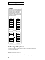
USING THE UNIT SAFELY
U
S
I
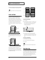
The
symbol alerts the user to important instructions N
or warnings.The specific meaning of the symbol is G
determined by the design contained within the T
triangle. In the case of the symbol at left, it is used for H
general cautions, warnings, or alerts to danger.
E
The
symbol alerts the user to items that must never
be carried out (are forbidden). The specific thing that U
must not be done is indicated by the design contained N
within the circle. In the case of the symbol at left, it I
T
means that the unit must never be disassembled.
Used for instructions intended to alert
the user to the risk of death or severe
injury should the unit be used
improperly.
Used for instructions intended to alert
the user to the risk of injury or material
damage should the unit be used
improperly.
* Material damage refers
other adverse effects
respect to the home
furnishings, as well
animals or pets.
to damage or
caused with
and all its
to domestic
The ● symbol alerts the user to things that must be S
carried out. The specific thing that must be done is A
indicated by the design contained within the circle. In F
the case of the symbol at left, it means that the power- E
L
cord plug must be unplugged from the outlet.
Y
001
015
• Before using this unit, make sure to read the
instructions below, and the rest of the VS-1680
User’s Guide.
• Do not force the unit’s power-supply cord to share
an outlet with an unreasonable number of other
devices. Be especially careful when using
extension cords—the total power used by all
devices you have connected to the extension
cord’s outlet must never exceed the power rating
(watts/amperes) for the extension cord. Excessive
loads can cause the insulation on the cord to heat
up and eventually melt through.
..........................................................................................................
002b
• Do not open or perform any internal modifications on the unit. (The only exception would be
where this user’s guide provides specific instructions that should be followed in order to install
user-installable options; see p. ???.)
..........................................................................................................
007
• Make sure you always have the unit placed so it is
level and sure to remain stable. Never place it on
stands that could wobble, or on inclined surfaces.
..........................................................................................................
009
• Do not excessively twist or bend the power cord,
nor place heavy objects on it. Doing so can
damage the cord, producing severed elements and
short circuits. Damaged cords are fire and shock
hazards!
..........................................................................................................
016
• Before using the unit in a foreign country, consult
with your retailer, the nearest Roland Service
Center, or an authorized Roland distributor, as
listed on the "Information" page.
..........................................................................................................
022a
• Always turn the unit off and unplug the power
cord before attempting installation of the Hard
disk drive unit or effect expansion board.
013
• In households with small children, an adult
should provide supervision until the child is
capable of following all the rules essential for the
safe operation of the unit.
..........................................................................................................
014
• Protect the unit from strong impact.
(Do not drop it!)
3
USING THE UNIT SAFELY
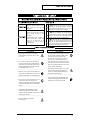
Conventions Used in This User’s Guide
101a
• The unit should be located so that its location or
position does not interfere with its proper ventilation.
..........................................................................................................
102b
• Always grasp only the plug on the power-supply
cord when plugging into, or unplugging from, an
outlet or this unit.
..........................................................................................................
104
• Try to prevent cords and cables from becoming
entangled. Also, all cords and cables should be
placed so they are out of the reach of children.
..........................................................................................................
106
• Never climb on top of, nor place heavy objects on
the unit.
..........................................................................................................
107b
• Never handle the power cord or its plugs with wet
hands when plugging into, or unplugging from,
an outlet or this unit.
..........................................................................................................
108a
• Before moving the unit, disconnect the power
plug from the outlet, and pull out all cords from
external devices.
..........................................................................................................
109a
• Before cleaning the unit, turn off the power and
unplug the power cord from the outlet (p. ???).
..........................................................................................................
110a
• Whenever you suspect the possibility of lightning
in your area, pull the plug on the power cord out
of the outlet.
..........................................................................................................
115a
• When installing the hard disk drive unit (HDP88
series) or Effect expansion board (VS8F-2), remove
only the specified screws. In some countries, an
internal IDE hard drive is pre-installed at the factory.
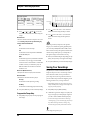
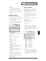
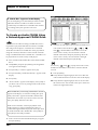
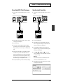
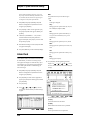
• The
icon will appear when there is significant
additional information about a topic at the specified
VS-1680 Quick Start or VS-1680 Appendices pages.
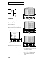
• Front panel buttons are indicated by square brackets [ ]
when not referred to using the word “button.” For
example, you may see “[STOP],” or “the STOP button.”
• The VS-1680 has two different buttons labeled PLAY. In
this user’s guide, they are differentiated as follows:
[PLAY] indicates the transport control button to begin
song playback.
[PLAY (DISPLAY)] indicates the button located to the left
of the TIME/VALUE dial.
• Some buttons have more than one label. The button label
written in white with a white line box around it (for
example, STORE) indicates the function the button
performs when [SHIFT] is pressed together with this
button. In this user’s guide, typically only the primary
button function will be indicated. However, for a few
cases, both button labels will be indicated, such as when
indicating [PLAY (DISPLAY)].
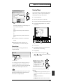
• The label for a FUNCTION button will appear directly
above the button in the display, for example, [F1
(ZOOM+)].
• Commands or questions appearing in the display are
indicated in quotes. For example, "STORE Current ?"
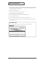
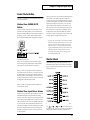
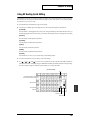
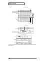
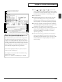
• The mixer section of the VS-1680 has a row of STATUS
buttons for each of the tracks. The command "Press Track
3 STATUS" means "press the STATUS button for Track 3."
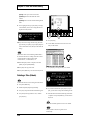
• The mixer section has a row of SELECT buttons for each
of the ten inputs, and a row of SELECT buttons for each
of the 16 tracks. Input SELECT buttons will be differentiated from Track SELECT buttons as follows: "Press
Track 4 SELECT" or "Press Input 7 SELECT." The top row
of SELECT buttons are the Input Selects. The middle row
of buttons are the Track Selects. (The bottom row of
buttons are not SELECT buttons—they are the TRACK
STATUS buttons).
• This user’s guide describes the functionality of a VS-1680
using software version 2.00 or higher. You can upgrade
your VS-1680 by downloading the necessary files from
the Roland US Web site (www.rolandus.com), or by
calling Roland Customer Service at (323) 890-3700, x2289.
4
IMPORTANT NOTES
In addition to the items listed under “IMPORTANT SAFETY
INSTRUCTIONS” and “USING THE UNIT SAFELY” on p. 2p. 3, please read and observe the following:
Power Supply
• Do not use this unit on the same power circuit with any
device that will generate line noise (such as an electric
motor or variable lighting system).
• Before connecting this unit to other devices, turn off the
power to all units. This will help prevent malfunctions
and/or damage to speakers or other devices.
Placement
• Using the unit near power amplifiers (or other
equipment containing large power transformers) may
induce hum. To alleviate the problem, change the
orientation of this unit; or move it farther away from the
source of interference.
• This device may interfere with radio and television
reception. Do not use this device in the vicinity of such
receivers.
• Do not expose the unit to direct sunlight, place it near
devices that radiate heat, leave it inside an enclosed
vehicle, or otherwise subject it to temperature extremes.
Excessive heat can deform or discolor the unit.
Maintenance
• For everyday cleaning, wipe the unit with a soft, dry
cloth or one that has been slightly dampened with water.
To remove stubborn dirt, use a cloth impregnated with a
mild, non-abrasive detergent. Afterwards, be sure to
wipe the unit thoroughly with a soft, dry cloth.
• Never use benzine, thinners, alcohol or solvents of any
kind to avoid the possibility of discoloration and/or
deformation.
Repairs and Data
• Please be aware that all data contained in the unit’s
memory may be lost when the unit is sent for repairs.
Important data should always be backed up on a storage
device (e.g., hard disk or Zip disk) or DAT recorder, or
written down on paper (when possible). During repairs,
due care is taken to avoid the loss of data. However, in
certain cases (such as when circuitry related to memory
itself is out of order), we regret that it may not be
possible to restore the data, and Roland assumes no
liability concerning such loss of data.
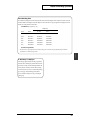
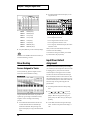
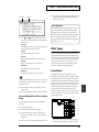
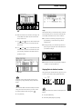
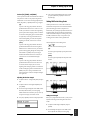
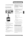
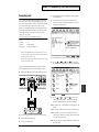
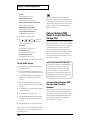
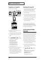
Memory Backup
• This unit contains a battery which powers the unit’s
memory circuits while the main power is off. When this
battery becomes weak, the message shown below will
appear in the display. Once you see this message, have
the battery replaced with a fresh one as soon as possible
to avoid the loss of all data in memory. To have the
battery replaced, consult with your retailer, the nearest
Roland Service Center, or an authorized Roland
distributor, as listed on the “Information” page.
fig.00-02
Additional Precautions
• Please be aware that the contents of memory can be
irretrievably lost as a result of a malfunction, or the
improper operation of the unit. To protect yourself
against the risk of losing important data, we recommend
that you periodically save a backup copy of important
data you have stored in the unit’s memory on a storage
device (e.g., hard disk or Zip disk), or DAT recorder.
• Unfortunately, it may be impossible to restore the
contents of data that was stored on a storage device (e.g.,
hard disk or Zip disk), or DAT recorder once it has been
lost. Roland Corporation assumes no liability concerning
such loss of data.
• Use a reasonable amount of care when using the unit’s
buttons, sliders, or other controls; and when using its
jacks and connectors. Rough handling can lead to
malfunctions.
• Never strike or apply strong pressure to the display.
• When connecting/disconnecting all cables, grasp the
connector itself—never pull on the cable. This way you
will avoid causing shorts, or damage to the cable’s
internal elements.
• A small amount of heat will radiate from the unit during
normal operation.
• To avoid disturbing your neighbors, try to keep the
5
IMPORTANT NOTES
unit’s volume at reasonable levels. You may prefer to use
headphones, so you do not need to be concerned about
those around you (especially when it is late at night).
• To transport the VS-1680, pack it in its original shipping
carton, using the included packing or equivalent
material. If an internal IDE hard disk (HDP88 series) is
installed, then remove the hard disk. Place the hard disk
in its carton and set this in the specified place inside the
VS-1680 shipping carton. The unit is now ready to be
transported. Moving the VS-1680 with the hard disk
installed may result in the loss of song data or damage to
the hard disk.
Handling the Disk Drive
accustomed to the new environment (allow a few hours)
before operating it.
Concerning Copyright
The law prohibits the unauthorized recording, public
performance, broadcast, sale, or distribution etc. of a work
(CD recording, video recording, broadcast, etc.) whose
copyright is owned by a third party.
The VS-1680 does not implement SCMS. This design decision
was made with the intent that SCMS should not restrict the
creation of original compositions that do not violate
copyright law. Roland will take no responsibility for any
infringement of copyright that you may commit in using the
VS-1680.
For details on hard disk handling, refer also to the
instructions that accompanied your hard disk.
SCMS (See Appendices, p. 64)
Before performing any of the following actions, be sure to
perform the shutdown procedure. Failure to do so may result
in the loss of song data or damage to the hard disk.
• Turning off the power of the VS-1680
• Turning off the power of the disk drive connected with
SCSI connector
• Removing a disk from a removable disk drive connected
with SCSI connector
Disclaimer of Liability
Roland will take no responsibility for any direct damages,
consequential damages, or any other damages which may
result from your use of the VS-1680. These damages may
include but are not limited to the following events which can
occur when using the VS-1680.
• Any loss of profit that may occur to you.
Shutdown (See Appendices, p. 64)
• Permanent loss of your music or data.
• Inability to continue using the VS-1680 itself or a
connected device.
Removable Disk Drive (See Appendices, p. 64)
When the VS-1680 MIDI/DISK indicator or disk drive busy
indicator is lit, it means that data is being written to or from
the hard disk. If you are using a removable disk drive,
confirm that this indicator is not lit before removing disks.
• While using the VS-1680, be careful not to subject the
unit to vibration or shock, and avoid moving the unit
while the power is turned on.
• Install the unit on a solid, level surface in an area free
from vibration. However, if installation on a flat surface
is not possible, the unit may be installed at a slight angle.
• Avoid using the unit immediately after it has been
moved to a location with a level of humidity that is
greatly different than its former location. Rapid changes
in the environment can cause condensation to form
inside the drive, which will adversely affect the
operation of the drive and/or damage removable disks.
When the unit has been moved, allow it to become
6
About the License Agreement
The VS-1680 and its CD-R capability are designed to allow
you to reproduce material to which you have copyright, or
material which the copyright owner has granted you
permission to copy. Accordingly, reproduction of music CDs
or other copyrighted material without the permission of the
copyright owner, other than for your own personal use and
enjoyment (private use) constitutes copyright infringement,
which may incur penalties. Consult a copyright specialist or
special publications for more detailed information on
obtaining such permission from copyright holders.
Table of Contents
USING THE UNIT SAFELY......................................................................3
IMPORTANT NOTES ...............................................................................5
Power Supply.............................................................................................................................................. 5
Placement..................................................................................................................................................... 5
Maintenance ................................................................................................................................................ 5
Repairs and Data ........................................................................................................................................ 5
Memory Backup ......................................................................................................................................... 5
Additional Precautions.............................................................................................................................. 5
Handling the Disk Drive ........................................................................................................................... 6
Concerning Copyright ............................................................................................................................... 6
Disclaimer of Liability................................................................................................................................ 6
About the License Agreement .................................................................................................................. 6
Table of Contents....................................................................................7
Preparations ..........................................................................................17
About the Package Contents................................................................................................................... 17
Main Features............................................................................................................................................ 17
The Latest in Compact Home Studio Environments ............................................................... 17
Simple Operation .......................................................................................................................... 18
Connectivity................................................................................................................................... 18
Major Options ................................................................................................................................ 18
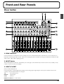
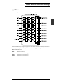
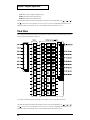
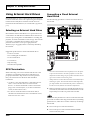
Front and Rear Panels..........................................................................19
Mixer Section............................................................................................................................................. 19
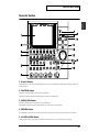
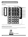
Recorder Section ....................................................................................................................................... 21
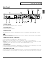
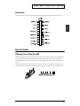
Rear Panel .................................................................................................................................................. 23
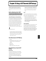
Chapter 1 Before You Start (VS-1680 Terminology) ..........................25
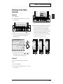
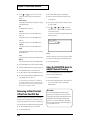
Saving and Managing Data..................................................................................................................... 25
Managing Disk Contents (Partitioning)..................................................................................... 25
The Location Where a Performance is Recorded (Song) ......................................................... 25
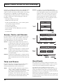
Sources, Tracks, and Channels.................................................................................................... 26
Takes and Phrases ......................................................................................................................... 26
About Events ................................................................................................................................. 26
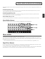
About Button Names .................................................................................................................... 27
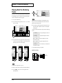
Mixer Section............................................................................................................................................. 27
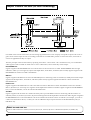
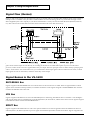
Signal Flow (Busses) ..................................................................................................................... 27
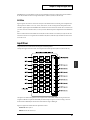
Input Mixer .................................................................................................................................... 29
Track Mixer .................................................................................................................................... 30
Switching the Fader Functions.................................................................................................... 30
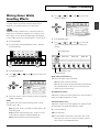
Master Block................................................................................................................................... 31
Recorder Section ....................................................................................................................................... 31
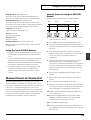
Differences from a Tape-Type MTR ........................................................................................... 31
Track Minutes and Recording Time........................................................................................... 32
Auxiliary Tracks for Each Track ................................................................................................. 33
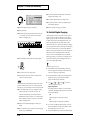
Effects Section ........................................................................................................................................... 34
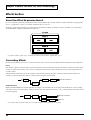
About the Effect Expansion Board ............................................................................................. 34
Connecting Effects ........................................................................................................................ 34
7
Table of Contents
Chapter 2 Basic Operation...................................................................35
Before You Begin ...................................................................................................................................... 35
Turning On the Power.................................................................................................................. 35
If You Have Trouble Understanding Displays or Operations ............................................... 35
Operating the VS-1680 ............................................................................................................................. 35
Basic Navigation ....................................................................................................................................... 36
Setting the Internal Clock ........................................................................................................................ 37
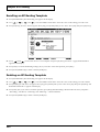
Before You Finish ..................................................................................................................................... 38
Saving Your Song.......................................................................................................................... 38
Turning Off the Power ................................................................................................................. 38
Restarting ....................................................................................................................................... 39
Chapter 3 Playback Operations...........................................................41
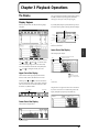
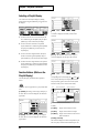
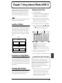
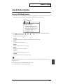
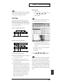
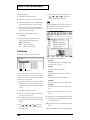
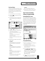
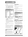
The Display................................................................................................................................................ 41
Display Regions............................................................................................................................. 41
Selecting a Playlist Display.......................................................................................................... 42
Function Buttons (While on the Playlist Display) .................................................................... 42
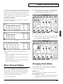
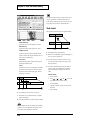
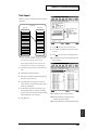
Mixer Channel Display............................................................................................................................ 43
Changing Track Status............................................................................................................................. 43
Muting and Soloing.................................................................................................................................. 44
Muting Tracks................................................................................................................................ 44
Muting Inputs and Effect Returns .............................................................................................. 44
Quick Soloing................................................................................................................................. 44
Solo Mode....................................................................................................................................... 44
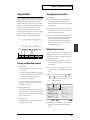
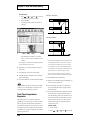
Using Locators .......................................................................................................................................... 45
Storing and Recalling Locators ................................................................................................... 45
Changing the Locator Bank ......................................................................................................... 45
Editing Stored Locators................................................................................................................ 45
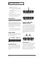
Using Markers........................................................................................................................................... 46
Storing a Marker............................................................................................................................ 46
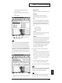
Locate to a Marker Using PREVIOUS and NEXT .................................................................... 46
Editing Marker Values ................................................................................................................. 47
Clearing Markers........................................................................................................................... 47
Other Ways to Move In a Song............................................................................................................... 48
Changing Playback Position Using JUMP................................................................................. 48
Change Playback Position Using TIME/VALUE Dial ............................................................ 48
Move to the Beginning or End of a Song Using FF and RW................................................... 48
Store Your Song ........................................................................................................................................ 48
Protecting Songs (Song Protect) ............................................................................................................. 49
Selecting and Loading Songs .................................................................................................................. 49
Chapter 4 Recording Operations.........................................................51
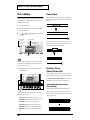
Preparing for a New Recording ............................................................................................................. 51
Create a New Song........................................................................................................................ 51
The Recording and Mixing Process ....................................................................................................... 54
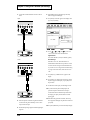
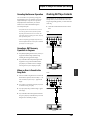
Connecting Instruments .......................................................................................................................... 55
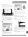
Recording to the Tracks ........................................................................................................................... 55
Recording on Other Tracks (Overdubbing).......................................................................................... 58
Recording Using Different Virtual Tracks (V-Tracks) ........................................................................ 58
Saving a Recorded Performance (Song Store)...................................................................................... 58
Track STATUS Buttons ............................................................................................................................ 58
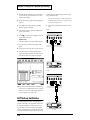
Manual Punch-In/Punch-Out ................................................................................................................ 59
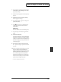
Loop Recording ........................................................................................................................................ 62
Undo and Redo......................................................................................................................................... 64
Track Bouncing ......................................................................................................................................... 64
Track Bouncing With Effects .................................................................................................................. 66
Recording a Digital Source...................................................................................................................... 66
8
Table of Contents
Using the Metronome .............................................................................................................................. 67
Saving Your Recordings .......................................................................................................................... 68
Chapter 5 Using the Digital Mixer........................................................69
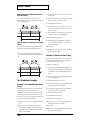
Signal Flow (Busses)................................................................................................................................. 70
Signal Busses in the VS-1680................................................................................................................... 70
RECORDING Bus ......................................................................................................................... 70
MIX Bus .......................................................................................................................................... 70
EFFECT Bus ................................................................................................................................... 70
AUX Bus ......................................................................................................................................... 71
Input Mixer................................................................................................................................................ 71
Track Mixer ............................................................................................................................................... 72
Fader/Mute Button .................................................................................................................................. 73
Method One: FADER/MUTE Button......................................................................................... 73
Method Two: Input Mixer Screen............................................................................................... 73
Master Block.............................................................................................................................................. 73
Determining Output ................................................................................................................................ 74
MONITOR Output Connectors................................................................................................... 74
AUX Connectors............................................................................................................................ 74
Digital Out Connectors................................................................................................................. 75
Direct Out Connectors.................................................................................................................. 75
Mixer Routing ........................................................................................................................................... 76
Sources Assigned to Tracks ......................................................................................................... 76
Input Mixer Default Assignment ........................................................................................................... 76
Stereo Link................................................................................................................................................. 77
Unlink Stereo Mixer Channels .................................................................................................... 77
Link Adjacent Mixer Channels.................................................................................................... 77
Adjust the Levels of Linked Channels ....................................................................................... 77
Adjusting the Panning of Stereo Linked Channels .................................................................. 78
Linking the Faders of Two or More Channels (Fader Group)................................................ 78
Selecting V-Tracks......................................................................................................................... 79
Using the Equalizer (EQ)......................................................................................................................... 79
Attenuation .................................................................................................................................... 81
Phase ............................................................................................................................................... 81
Copying Mixer Settings ........................................................................................................................... 82
Mixer Scenes.............................................................................................................................................. 83
Scene................................................................................................................................................ 83
EZ Routing ..................................................................................................................................... 83
Chapter 6 Mixer Channel Strip Detail..................................................85
Input Mixer................................................................................................................................................ 85
[F1 (MIX)] MIX Bus Enable/Pan................................................................................................. 85
[F2 (Low)], [F3 (Mid)], and [F4 (High)] Equalizer.................................................................... 85
[F6 (PRM.V)] Parameter View/[F6 (CH.V)] Channel View.................................................... 85
[F1 (EFX1)] Effect 1 Send.............................................................................................................. 85
[F2 (EFX2)] Effect 2 Send.............................................................................................................. 86
[F3 (EFX3)] Effect 3 Send.............................................................................................................. 86
[F4 (EFX4)] Effect 4 Send.............................................................................................................. 86
[F5 (AUX)] AUX Send .................................................................................................................. 86
[F1 (Ef1In)] Effect 1 Insert ............................................................................................................ 86
[F2 (Ef2In)] Effect 2 Insert ............................................................................................................ 87
[F3 (Ef3In)] Effect 3 Insert ............................................................................................................ 87
[F4 (Ef4In)] Effect 4 Insert ............................................................................................................ 88
[F1 (Link)] Stereo Link.................................................................................................................. 88
[F2 (ATT)] Attenuation................................................................................................................. 88
[F3 (Phase)] PHASE ...................................................................................................................... 88
[F4 (Group)] FADER GROUP ..................................................................................................... 88
9
Table of Contents
[F1 (Meter)] METER...................................................................................................................... 88
[F3 (Solo)] SOLO............................................................................................................................ 88
[F4 (Mute)] MUTE......................................................................................................................... 88
[F5 (Fader)] FADER ...................................................................................................................... 89
Track Mixer ............................................................................................................................................... 89
[F1 (MIX)] MIX Bus Enable/Pan................................................................................................. 89
[F2 (Low)], [F3 (Mid)], and [F4 (High)] Equalizer.................................................................... 89
[F5 (V.Trk)] V-Track Select........................................................................................................... 89
[F6 (PRM.V)] Parameter View/[F6 (CH.V)] Channel View.................................................... 89
[F1(EFX1)] Effect 1 Send............................................................................................................... 89
[F2 (EFX2)] Effect 2 Send.............................................................................................................. 90
[F3 (EFX3)] Effect 3 Send.............................................................................................................. 90
F4 (EFX4)] Effect 4 Send ............................................................................................................... 90
[F5 (AUX)] AUX Send .................................................................................................................. 90
[F1 (Ef1In)] Effect 1 Insert ............................................................................................................ 90
[F2 (Ef2In)] Effect 2 Insert ............................................................................................................ 91
[F3 (Ef3In)] Effect 3 Insert ............................................................................................................ 91
[F4(Ef4In)] Effect 4 Insert ............................................................................................................. 92
[F1 (Link)] Stereo Link.................................................................................................................. 92
[F2 (ATT)] Attenuation................................................................................................................. 92
[F3 (Phase)] PHASE ...................................................................................................................... 92
[F4 (Group)] FADER GROUP ..................................................................................................... 92
[F1 (Meter)] METER...................................................................................................................... 92
[F2 (Stats)] STATUS ...................................................................................................................... 92
[F3 (Solo)] SOLO............................................................................................................................ 93
[F4 (Mute)] MUTE......................................................................................................................... 93
[F5 (Fader)] FADER ...................................................................................................................... 93
Master Block.............................................................................................................................................. 93
[F1 (MST)] MASTER ..................................................................................................................... 93
[F2 (MON)] MONITOR ................................................................................................................ 93
[F3 (AUX.A)] AUX A .................................................................................................................... 93
[F4 (AUX.B)] AUX B ..................................................................................................................... 93
[F5 (DOUT1)] DIGITAL OUT 1................................................................................................... 93
[F6 (DOUT2)] DIGITAL OUT 2................................................................................................... 94
[F1 (Ef1In)] Effect 1 Insert ............................................................................................................ 94
[F2 (Ef2In)] Effect 2 Insert ............................................................................................................ 94
[F3 (Ef3In)] Effect 3 Insert ............................................................................................................ 94
[F4 (Ef4In)] Effect 4 Insert ............................................................................................................ 95
[F5 (DIR)] DIRECT OUT .............................................................................................................. 95
[F1 (EFX1)] Effect 1 Master Send................................................................................................. 95
[F2 (EFX2)] Effect 2 Master Send................................................................................................. 95
[F3 (EFX3)] Effect 3 Master Send................................................................................................. 95
[F4 (EFX4)] Effect 4 Master Send................................................................................................. 95
[F5 (AUX)] AUX Master Send ..................................................................................................... 96
Chapter 7 Using Internal Effects (VS8F-2)..........................................97
Location of Effects .................................................................................................................................... 97
Procedure for Using Effects .................................................................................................................... 97
Selecting Effect Patches............................................................................................................................ 97
Selecting a Preset Patch ................................................................................................................ 97
Creating and Saving User Effect Patches................................................................................... 98
Effect Types ............................................................................................................................................... 99
Insert Effects................................................................................................................................... 99
Effect Send-and-Return Loops .................................................................................................. 100
Making the Effect Connection ................................................................................................... 100
10
Table of Contents
Connecting Effects.................................................................................................................................. 100
Connecting Insert Effects in the Input and Track Mixer ....................................................... 100
Connecting Insert Effects in the Master Block ........................................................................ 101
Three Insert Effect Examples ..................................................................................................... 102
Connecting Effect Send-and-Return Loops............................................................................. 103
Effects Return Section................................................................................................................. 104
Two Examples of Using Effect Send-and-Return Loops ....................................................... 104
Using Effects While Recording............................................................................................................. 105
Listening to an Insert Effect While Recording ........................................................................ 106
Listening to a Loop Effect While Recording ........................................................................... 106
Recording Insert Effects ............................................................................................................. 106
Recording an Effect Send-and-Return Loop ........................................................................... 107
Recording Stereo Effects........................................................................................................................ 108
Three Important Reminders About Using Effects ............................................................................. 108
Chapter 8 EZ Routing .........................................................................109
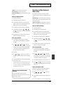
Using EZ Routing Step Editing ............................................................................................................ 109
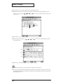
Setting Up for Recording Using Step Editing ......................................................................... 110
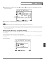
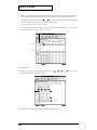
Setting Up for Mixing Using Step Editing............................................................................... 113
Setting Up for Bouncing Using Step Editing........................................................................... 115
Using EZ Routing Quick Editing ......................................................................................................... 119
Using EZ Routing Templates................................................................................................................ 121
Saving an EZ Routing Template ............................................................................................... 121
Recalling an EZ Routing Template........................................................................................... 122
Deleting an EZ Routing Template ............................................................................................ 122
Chapter 9 Automix ..............................................................................123
Mixer Automation .................................................................................................................................. 123
Using Automix........................................................................................................................................ 124
Adjust the Display for Automix................................................................................................ 124
Realtime Automix................................................................................................................................... 124
Realtime Automix of Track Faders........................................................................................... 124
Realtime Automix of Input Faders ........................................................................................... 125
Automating the Master Stereo Mix and Monitor Output ..................................................... 125
Automating Effect Returns ........................................................................................................ 125
Snapshot Automation ............................................................................................................................ 126
Snap Mode ................................................................................................................................... 126
Automating Effect Changes .................................................................................................................. 127
Gradation...................................................................................................................................... 127
Two Gradation Examples .......................................................................................................... 128
Updating Automix...................................................................................................................... 129
Understanding Fader Match ..................................................................................................... 129
Editing Automix Data (Micro Edit).......................................................................................... 130
Erasing Automix Data on Specified Channels........................................................................ 136
Erasing Automix Data ................................................................................................................ 136
Saving and Exiting Automix ..................................................................................................... 137
Chapter 10 Track and Phrase Editing ...............................................139
Track Editing........................................................................................................................................... 139
Track Erase ................................................................................................................................... 139
Track Cut ...................................................................................................................................... 140
Track Move .................................................................................................................................. 141
Track Copy ................................................................................................................................... 143
Track Insert .................................................................................................................................. 144
Track Exchange............................................................................................................................ 145
Track Time Compression/Expansion ...................................................................................... 146
Track Name.................................................................................................................................. 148
11
Table of Contents
Track Import ................................................................................................................................ 149
Phrase Editing ......................................................................................................................................... 150
Phrase Delete ............................................................................................................................... 150
Dividing a Phrase (Phrase Divide/Split)................................................................................. 150
Phrase Move................................................................................................................................. 153
Phrase Copy ................................................................................................................................. 153
Phrase Trim In ............................................................................................................................. 153
Phrase Trim Out .......................................................................................................................... 153
Phrase New .................................................................................................................................. 154
Naming Takes.............................................................................................................................. 155
Deleting a Take (Delete) ............................................................................................................. 156
Chapter 11 Editing Tips & Tools........................................................157
Editing Operations ................................................................................................................................. 157
Steps for Track Editing .......................................................................................................................... 157
Step 1: Set the Edit Points........................................................................................................... 157
Step 2: Perform the Button-Pushes to Complete the Edit ..................................................... 161
Track Editing vs. Phrase Editing.......................................................................................................... 162
An Editing Note of Caution .................................................................................................................. 163
Practical Editing Application................................................................................................................ 163
Chapter 12 Song Editing ....................................................................165
Song Arrange .......................................................................................................................................... 165
Song Split ................................................................................................................................................. 166
Song Combine ......................................................................................................................................... 167
Chapter 13 Mastering .........................................................................169
Mastering ................................................................................................................................................. 169
Mixing Down to Mastering Tracks ...................................................................................................... 169
Mastering Tracks Status Shortcuts ........................................................................................... 171
Playing Back the Mastering Tracks...................................................................................................... 172
Mixing Down While Inserting Effects ................................................................................................. 173
To Prohibit Digital Copying ...................................................................................................... 174
Connecting the CD-R/CD-RW Drive.................................................................................................. 175
Creating an Audio CD ........................................................................................................................... 175
Items Necessary for Creating an Audio CD............................................................................ 175
Creating a Master Stereo Mix .................................................................................................... 176
Finalizing...................................................................................................................................... 176
Assembling Multiple Songs for CD Recording.................................................................................. 177
Copyright Protection .................................................................................................................. 177
CD Track Numbers ..................................................................................................................... 177
Writing Songs to CD-R Discs .................................................................................................... 178
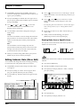
Adding a Song to a Partially Recorded Disc ........................................................................... 180
Arranging and Recording Multiple Songs to a CD-R Disc ................................................... 180
CD Player Function ................................................................................................................................ 181
To Create an Audio CD-RW Using a Roland-Approved CD-RW Drive ............................ 182
Chapter 14 Other Useful Functions...................................................185
Vari Pitch ................................................................................................................................................. 185
Numerics/ASCII .................................................................................................................................... 185
Entering Numbers....................................................................................................................... 185
Entering Letters ........................................................................................................................... 185
Stereo Input ............................................................................................................................................. 185
Removing a Direct Current Offset from the MIX Bus....................................................................... 186
Using the MONITOR Knob to Adjust Channel Panning ................................................................. 186
Shut Down and Restart.......................................................................................................................... 187
Turning Off the Power ............................................................................................................... 187
12
Table of Contents
Chapter 15 Using External MIDI Devices ..........................................189
Synchronizing with MIDI Sequencers................................................................................................. 189
Items Necessary for Synchronization....................................................................................... 189
Master and Slave ......................................................................................................................... 189
Using MTC ................................................................................................................................... 189
Synchronization Using the VS-1680 as the Master................................................................. 190
Synchronization Using the VS-1680 as the Slave.................................................................... 191
Using MTC Offset ....................................................................................................................... 191
Using the Sync Track (Master) .................................................................................................. 192
Recording MIDI Clock Messages.............................................................................................. 193
Synchronized Operation ............................................................................................................ 193
Using the Tempo Map................................................................................................................ 194
Synchronized Operation ............................................................................................................ 195
Other Methods to Generate A Sync Track or Tempo Map ................................................... 195
Using MIDI Controller Messages......................................................................................................... 198
Switching Track Status ............................................................................................................... 198
Switching Scenes ......................................................................................................................... 199
Switching Effects ......................................................................................................................... 199
Adjusting Effects ......................................................................................................................... 199
Using an External MIDI Sound Source to Play the Metronome...................................................... 200
Using an External MIDI Device to Adjust the Mixer (Compu Mix) ............................................... 201
Preparations for Compu Mix..................................................................................................... 203
Recording with Compu Mix...................................................................................................... 203
MIDI Machine Control........................................................................................................................... 204
Chapter 16 Using Software Sequencers...........................................205
Common Terms ...................................................................................................................................... 205
MIDI Clock................................................................................................................................... 205
MIDI Time Code (MTC)............................................................................................................. 205
MIDI Machine Control (MMC) ................................................................................................. 205
Song Position Pointer (SPP)....................................................................................................... 205
Synchronization........................................................................................................................... 205
Sequencer Tracks......................................................................................................................... 205
MIDI Interface.............................................................................................................................. 205
Specific Software Applications............................................................................................................. 206
Cakewalk Pro Audio .................................................................................................................. 206
Cubase VST .................................................................................................................................. 207
Logic Audio.................................................................................................................................. 208
Digital Performer ........................................................................................................................ 209
Vision DSP.................................................................................................................................... 210
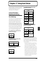
Chapter 17 Using Hard Drives ...........................................................213
General Information Regarding Hard Drives .................................................................................... 213
Drive Partitioning ....................................................................................................................... 213
Recording Times vs. Sample Rate/Recording Modes........................................................... 214
Checking Remaining Space ....................................................................................................... 214
Recovering Drive Space......................................................................................................................... 214
Song Optimize ............................................................................................................................. 214
Song Erase .................................................................................................................................... 215
Using External Hard Drives.................................................................................................................. 216
Selecting an External Hard Drive ............................................................................................. 216
SCSI Termination ........................................................................................................................ 216
Connecting a Fixed External Hard Drive ................................................................................ 216
Connecting a Removable External Hard Drive ...................................................................... 217
Initializing (Formatting) the Drive ........................................................................................... 217
Saving a Song to an External Drive .......................................................................................... 218
Loading a Song from an External Drive Using Song Copy Playable .................................. 221
13
Table of Contents
Drive Select .................................................................................................................................. 222
Loading a Song from External Disks using Song Archive Extract ...................................... 222
Hard Drive Maintenance....................................................................................................................... 223
Drive Initialize ............................................................................................................................. 223
Drive Check.................................................................................................................................. 224
Check Drive Reliability using Surface Scan ............................................................................ 225
Backup Options ...................................................................................................................................... 226
DAT Backup................................................................................................................................. 226
External Removable Drive ......................................................................................................... 226
Roland VS-CDR Backup............................................................................................................. 226
Chapter 18 CD Backup .......................................................................227
Connecting the CD-R/CD-RW Drive.................................................................................................. 227
CD-R Backup and Recover.................................................................................................................... 227
CD-R Backup ............................................................................................................................... 228
CD-R Recover .............................................................................................................................. 229
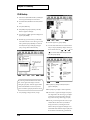
Chapter 19 Using a DAT Recorder (DAT Backup) ...........................231
Before Backing Up to DAT.................................................................................................................... 231
Items Necessary for DAT Backup............................................................................................. 231
About the Devices Used in DAT Backup ................................................................................ 231
Saving Song Data to DAT (Backup)..................................................................................................... 232
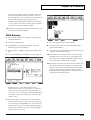
Recovering Data from a DAT ............................................................................................................... 233
Canceling the Recover Operation ............................................................................................. 235
Canceling a DAT Recovery Operation in Progress ................................................................ 235
When an Error is Found in the Song Data............................................................................... 235
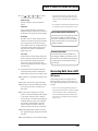
Checking DAT Tape Contents.............................................................................................................. 235
DAT Backup Verification ...................................................................................................................... 236
Chapter 20 Compatibility with Other VS Recorders ........................239
Drive Compatibility ............................................................................................................................... 239
VS-880/880EX Æ VS-1680.......................................................................................................... 239
VS-1680 Æ VS-880 ....................................................................................................................... 239
VS-840/840EX ´ VS-1680 ............................................................................................................ 239
Song Import............................................................................................................................................. 239
Song Export ............................................................................................................................................. 241
Chapter 21 System and Global Settings...........................................243
System Settings for Each Song.............................................................................................................. 243
Fader Match ................................................................................................................................. 243
Peak Hold ..................................................................................................................................... 243
Remaining Recording Time ....................................................................................................... 243
Foot Switch Settings.................................................................................................................... 244
Global Settings ........................................................................................................................................ 245
Shift Lock...................................................................................................................................... 245
Numerics Type ............................................................................................................................ 245
Measure Display.......................................................................................................................... 246
SCSI ID Number.......................................................................................................................... 246
IDE Drive Switch......................................................................................................................... 247
Input Peak Level.......................................................................................................................... 247
Previous/Next Switch ................................................................................................................ 247
Adjusting the Button Sensitivity............................................................................................... 248
Fan Control .................................................................................................................................. 248
Play and Record Settings....................................................................................................................... 249
Record Monitor............................................................................................................................ 249
Marker Stop.................................................................................................................................. 249
Fade Length ................................................................................................................................. 249
14
Table of Contents
Mixer and System Initialize .................................................................................................................. 249
Alarm Clock ............................................................................................................................................ 250
Chapter 22 Specific Applications ......................................................253
Syncing Two VS-1680s with MTC and MMC .................................................................................... 254
Settings for the Master VS.......................................................................................................... 254
Settings for the Slave VS............................................................................................................. 255
Syncing a VS-1680 and a VS-880/880EX............................................................................................. 255
Syncing the VS-880 to the VS-1680 Using MTC and MMC .................................................. 255
Using an External MIDI Device to Control the Mixer (Compu Mix) ............................................. 256
Correspondence Between MIDI Channels and Controller Numbers.................................. 256
Preparations for Compu Mix..................................................................................................... 258
Recording with Compu Mix...................................................................................................... 258
Synchronizing with Video Equipment................................................................................................ 258
Using External Effects Units ................................................................................................................. 259
Chapter 23 Frequently Asked Questions..........................................261
How Do I Control the Stereo Tracks Independently? ........................................................... 261
Why Do I Hear the Inputs All of the Time? ............................................................................ 261
What is the FADER/MUTE Button Used For? ....................................................................... 261
How Do I Burn Audio CDs?...................................................................................................... 261
How Do I Restore the Mixer Parameters to the Factory Settings?....................................... 263
How Do I Create a Tempo Map? .............................................................................................. 263
How Do I Use Automix?............................................................................................................ 264
How Do I Create a User Template in EZ Routing? ................................................................ 264
How Do I Bounce Tracks?.......................................................................................................... 265
How Do I Bounce Tracks with Effects?.................................................................................... 266
Why Can’t I Hear My Effects?................................................................................................... 266
How Do I Use the Scrub and Waveform Display Features?................................................. 267
How Do I Record a Stereo Signal?............................................................................................ 268
How Do I Know How Much Time I Have Left On My Hard Drive,
and How Big Is My Song?................................................................................................ 268
How Do I Import VS-880/880EX and VS-840/840EX Songs? .............................................. 268
How Do I Erase the Demo Songs? ............................................................................................ 269
Index.....................................................................................................271
15
Table of Contents
16
Preparations
The following items are included with the VS-1680. Please
check to make sure you have all the items.
• VS-1680
• AC cord
Preparations
About the Package Contents
measure drum pattern any number of times, or have the
same chorus both at the beginning and end of a song.
The VS-1680 uses “non-destructive editing.” This allows you
to cancel and recover up to 999 previous recording and
editing operations (Undo/Redo).
• VS-1680 Quick Start
• VS-1680 Owner’s Manual
• VS-1680 Appendices
Main Features
The Latest in Compact Home
Studio Environments
The VS-1680 retains all of the features of Roland’s VS-880
workstation, a revolution in the world of the home studio,
with the disk recorder, digital mixer, and multi effects
systematically and more organically integrated. From when
you start picking mics to when you actually record, to
mixdown, to adding effects, and on to creating the master
data for playing through a PA or mastering on a CD, you can
easily control every aspect of the recording process with the
VS-1680 in your home studio.
The internal clock runs on battery power, so it continues to
function even after the VS-1680’s power is turned off. This
allows you to manage your songs by “time stamp,” the time
and date of recording that is registered in the song data.
Digital Mixer Section
You can store all mixer settings, including fader levels, pan,
and effects. Stored settings can be recalled very simply, a
convenient feature when adjusting balances during mixdown
and comparing mixes with effects.
Changes in settings over time, such as fader levels and pan,
can also be stored (Automix), allowing you to perfect fadeins and fade-outs in your mixes.
You can easily set up the VS-1680 for different situations
such as recording, track bouncing, and mixdown using its
handy EZ Routing feature.
Disk Recorder Section
Effects Section
The digital disk recorder section provides 16 playback tracks,
and allows eight tracks to be recorded simultaneously. Each
track features 16 virtual tracks (V-Tracks), providing a total
of 256 tracks altogether. This means that you can record
multiple takes, make temporary mixes when editing and
create songs that require numerous tracks, all with room to
spare.
The VS-1680 features the optional VS8F-2 effect expansion
board. Up to two of these effect expansion boards can be
installed in the VS-1680. With the VS8F-2 effect installed in
the VS-1680, up to four high-quality stereo effects will be
available for your use.
The VS-1680’s recording functions were designed for use
with professional digital equipment—DAT recorders, digital
mixers, digital effects, etc. You can record and edit with topquality sound, losing none of that quality in the playback.
You can instantly find the location of sections in a song you
want to hear repeatedly (locator), or places that you wish to
record over by placing marks at such points (marker). These
markers are recalled by a simple procedure, and you will
never have to wait for any rewinding or fast-forwarding.
Sounds are organized in phrases. Copying, moving, and
inserting these phrase units (using Phrase Edit), as well as
many other editing processes, are possible with the VS-1680.
For example, you can create “break beats” by copying a four-
The VS8F-2 provides not only basic effects such as reverb and
delay, but also effects ideal for vocals and guitar (such as
guitar amp simulator) and even special effects such as RSS
and Roland’s exclusive COSM™ speaker modeling that you
can use when the VS-1680 is connected to digital speakers
such as Roland’s DS-90A Powered Monitors. These effects
are organized as 34 “algorithms” from which you can easily
create new sounds.
The VS8F-2 provides 240 read-only effects, or “preset
patches,” that are designed for various uses. In addition, the
VS8F-2 provides 200 read-and-write effects, “user patches,”
that can be customized and re-saved. As a result, you can
instantly switch between a wide variety of effects simply by
selecting a preset or user patch.
17
Preparations
Simple Operation
Major Options
The VS-1680 can be operated as easily as a conventional
multitrack recorder. You will be able to enjoy all of the
advantages of a home studio from the day of purchase.
Internal 2.5” IDE Hard Disk:
The VS-1680 uses the well-known graphics (“icons”) made
famous by Roland’s VG-8 and V-Drums. The large, full-dot
graphic display is backlit and inclined, so it is easy to read
when used on stage, or wherever high visibility is required.
Connectivity
A wide variety of connectors and jacks are provided,
including two balanced XLR connectors. The VS-1680
features a wide input sensitivity range—from mic level (-50
dBu) to line level (+4 dBu)—and phantom power, allowing
you to plug in condenser mics that require external power.
There are six sets of balanced input jacks, handling a wide
input sensitivity range, from line level (+4 dBu) to mic level
(-50 dBu). Furthermore, you can choose either the high-input
(GUITAR (Hi-Z)) jack for directly plugging in an electric
guitar, or the INPUT 8 jack.
Besides the RCA phono type (stereo) MASTER jacks, (stereo)
AUX A and AUX B jacks, and (stereo) MONITOR jacks are
also provided. You can monitor an effect send and other
outputs without affecting the MASTER OUT signal.
The VS-1680 provides both coaxial and optical digital I/O
connectors. With these, you can digitally connect the VS-1680
to popular consumer electronic devices such as CD players,
DAT recorders, MD recorders, and so on.
A SCSI connector (DB-25 type) is also provided, allowing
you to connect the VS-1680 to external SCSI devices such as a
Zip drive or CD-R drive.
MIDI IN and MIDI OUT/THRU connectors are also
provided. You can synchronize the VS-1680 with an external
MIDI sequencer, use the MIDI sequencer to control the VS1680’s mixer, sound an external MIDI sound generator with
the metronome, and more.
Besides tracks for recording audio signals, the VS-1680 has a
sync track for storing MIDI clock messages. You can even
synchronize MIDI sequencers that are not compatible with
MTC (MIDI Time Code) or MMC (MIDI Machine Control).
18
If your VS-1680 does not already have an internal hard disk,
we recommend that you install one. An internal hard disk
makes your entire VS-1680 studio more compact and easier
to transport, and eliminates connection problems that can
occur with an external disk drive. It is also required for
creating audio CDs directly from the VS-1680.
* In order to take full advantage of the VS-1680’s potential—the
number of tracks that can be recorded/played simultaneously
and recording capacity—we recommend that you use a hard
disk that is 2.1 GB in size or greater.
CD-R Drive (approved by Roland):
A CD-R or CD-RW drive connected with a SCSI connector.
Such a device allows you to create songs on the VS-1680 and
burn them onto your own original audio CDs. Additionally,
you can use a CD-R for backing up song data to inexpensive
CD-R discs.
VS8F-2:
An effect expansion board that can be installed in the VS1680. You can install two of these boards, each of which
supplies two stereo effects, for a total of four stereo effects or
eight mono effects.
* The VS8F-1 effect expansion board is for use with the VS-880.
It cannot be used in the VS-1680.
Front and Rear Panels
Mixer Section
fig.00-03
Front & Rear
Panels
1. PEAK Indicators
Use these indicators to confirm the correct recording level as set with the INPUT knobs. The indicators are set at the factory to
illuminate when the input audio reaches -6 dB. You can change the peak level indicator setting so the indicators illuminate when
audio reaches -3 dB, -6 dB or clipping (p. 247).
2. INPUT Knobs
These knobs adjust the sensitivity of the INPUT jacks 1 through 8. Turn the knob fully clockwise for mic level (-50 dBu), or fully
counter-clockwise for line level (+4 dBu).
3. SELECT/CH EDIT
(Select/Channel Edit) buttons
Use these buttons to change Input Mixer settings for the analog inputs, digital inputs, stereo inputs, and effect returns. The
currently selected channel’s indicators will light.
1–8:
Each channel (1–8)
DIGITAL:
Digital input
ST IN:
Stereo in
EFFECT 1/3 RTN:Effect 1 and 3 Return
19
Front and Rear Panels
EFFECT 2/4 RTN:Effect 2 and 4 Return
7. MONITOR Knob
You can assign an input to be recorded to a track by holding
down the track’s STATUS button, then pressing the desired
SELECT button for the input or source you wish to record.
This adjusts the volume level output from the MONITOR
jacks.
When numerics are combined with alphabetical characters
([NUMERIC/ASCII]), alphabetical characters can be input
directly (Song Name, etc.).
8. PHONES Knob
4. SELECT/CH EDIT
(Select/Channel Edit) buttons
Use these buttons when you wish to change Track Mixer
settings and to change track channels. The currently selected
channel’s indicators are lit.
1–15/16: Each channel (1–15/16)
This knob adjusts the volume of the headphones.
9. AUTOMIX Button
This button switches the Automix function on and off. The
button indicator lights when Automix is on.
10. EZ ROUTING Button
This button invokes the EZ Routing screen.
When you press these buttons while holding down the
STATUS button, you can select any desired bouncing
11. EDIT/SOLO Button
destination track.
Press this button to make block settings for the master
section of the mixer.
When numerics are combined with alphabetical characters
([NUMERIC/ASCII]), alphabetical characters can be input
directly (Song Name, etc.).
5. STATUS Buttons
These buttons switch the status of each track. The current
status is shown by the button indicator.
SOURCE (orange):
The input source or track assigned to the channel is being
output.
REC (blinking red):
Recording is selected for the track assigned to the channel.
During playback, the track data is normally output.
REC (blinking red and orange):
Recording is selected for the track assigned to the channel.
During playback, you will be able to listen to the track.
PLAY (green):
The track assigned to the channel will play back.
OFF (off):
The channel is muted (silent).
When pressed in combination with the SELECT/CH EDIT
button, this selects the source or track to be assigned to a
track for recording.
6. Channel Faders
Use these faders to adjust the volume level of each channel or
track.
20
To use the Solo function to monitor only a specific channel,
press this button while holding down the SELECT/CH EDIT
button.
12. FADER/MUTE Button
Each press of this button alternately assigns use of the
channel faders to the Input Mixer or to the Track Mixer. The
button indicator shows the faders’ current status.
To mute the channel, press this button while holding down
the SELECT/CH EDIT button.
13. Master Fader
Use this fader to adjust the overall output level.
Front and Rear Panels
Recorder Section
fig.00-04
Front & Rear
Panels
1. Graphic Display
This displays shows various data related to the current status of the VS-1680 during recording, playback, editing, changing its
settings, and so on.
2. FUNCTION Button
This button switches the display screen and executes operations.
The function currently assigned to each button appears at the bottom of the display.
3. PAGE (JUMP) Button
This button switches pages for screens that consist of several pages.
When [SHIFT] is held down together with this button, the Locator Jump screen is displayed.
4. PREVIEW Button
Press this button to use the Preview function that plays back a specific amount of time before and after the current location.
5. LOCATOR/SCENE Button
Pressing this button allows you to store or recall locators and markers or to store or recall Scenes (mixer settings).
21
Front and Rear Panels
PREVIOUS:
10. EXT SYNC (External Sync) Button
Recalls the most recent start or end point of a phrase. Pressed
with [SHIFT], this button recalls the previous marker.
Press this button to designate the VS-1680 or an external
MIDI device as the master, or main, controlling
synchronization device. With the VS-1680 selected as the
master, the external MIDI device functions as the slave unit;
with the external MIDI device is selected as the master, the
VS-1680 functions as the slave unit.
NEXT:
Recalls the next start or end point of a phrase. Pressed with
[SHIFT], this button recalls the next marker.
TAP:
Press this button to set markers.
BANK/9:
Pressing this with the LOCATOR buttons (1–8) selects the
locator bank.
SCENE/0:
This is pressed when storing, recalling, and deleting Scenes.
CLEAR (Back Space):
This button deletes locators, markers, and Scenes.
NUMERICS/ASCII:
Press this when you want to use the STATUS and LOCATOR
buttons for 10-key entry of Western numerals.
11. CURSOR Buttons
Normally (i.e. in Play mode), these buttons select the unit of
time measurement. When making settings (i.e. in Edit mode),
use these buttons to select parameters.
12. PLAY (DISPLAY) Button
Press this button to return to the screen that appears when
the VS-1680 is first turned on (normal playback status).
13. TIME/VALUE Dial
These select a locator or Scene.
In normal (playback) mode, this dial adjusts the current time
for playback. When making settings (i.e. when editing), use
this dial to change parameter values.
6. Transport Control Buttons
14. LOOP Button
These buttons operate the recorder.
This button turns Loop Recording on and off. Pressed
together with [LOCATOR], it specifies the range to be
recorded in Loop Recording.
1–8:
ZERO:
This returns the current time to “00h00m00s00”
(zero return).
REW:
The current time is moved back only while this
button is held down. This corresponds to the
rewind button on a tape recorder.
15. AUTO PUNCH Button
This button turns Auto Punch-In Recording on and off.
Pressed with the LOCATOR button, it specifies the range to
be recorded in Auto Punch-In Recording.
FF:
While this button is held down, the current time is
moved forward. This corresponds to the fastforward button on a tape recorder.
STOP:
Stops recording or playback of the song.
16. UNDO (REDO) Button
PLAY:
Starts recording or playback from the current
time.
REC:
Press this button to record a song.
Press this button to cancel a recording or editing step that
you have made (Undo function). Pressed with [SHIFT], this
button cancels the last Undo operation (Redo function).
7. CONTRAST Knob
17. SHIFT Button
Use this to adjust the brightness of the display screen.
This button is pressed in conjunction with other buttons to
access additional functions of those buttons.
8. VARI PITCH Button
Press this button when you wish to adjust the VS-1680’s
playback speed (Vari Pitch function).
18. ENTER/YES Button
This is pressed to execute the current operation or select the
current screen.
9. MIDI/DISK Indicator
This indicator lights green when MIDI messages are being
received, and red when data is being written or read on the
disk drive. If both occur, the indicator lights orange.
22
19. EXIT/NO Button
This is pressed to cancel the current operation or exit the
current screen.
Front and Rear Panels
Rear Panel
fig.00-05
Front & Rear
Panels
1. POWER Switch
This switch turns the VS-1680’s power on and off. See Chapter 2.
2. AC IN (AC Inlet)
Connect the included power cable here.
3. SCSI Connector
This is a DB-25 type SCSI connector for connecting SCSI devices such as an external hard disk, removable media, or a CD-R.
This connector is intended only for SCSI devices. If you connect any other other type of device to this jack, you may cause serious damage to
the VS-1680 and the connected device.
4. MIDI Connectors (IN, OUT/THRU)
Connect external MIDI devices (MIDI sequencers, MIDI controllers, etc.) here.
IN: This connector receives MIDI messages. Connect it to the MIDI OUT connector of an external MIDI device.
OUT/THRU: This connector can be used either as a MIDI OUT or as a MIDI THRU jack. With the factory settings, it will function
as a MIDI OUT connector, which means it is set to transmit MIDI messages generated by the VS-1680.
5. PHONES Jack
Connect your headphones (not supplied) here. The PHONES jack outputs the same signal as the MONITOR jack, and is affected
by the Master Fader setting, as well as the position of the MONITOR and PHONES knobs.
6. MONITOR Jacks (L, R)
RCA-phono-type analog audio output jacks. With the factory settings, all signals output from the MASTER OUT jacks also output
from the MONITOR jacks. This is determined by the block settings of the mixer’s master section and the settings of each channel.
23
Front and Rear Panels
7. AUX B Jacks (L, R)
8. AUX A Jacks (L, R)
RCA-phono-type analog audio output jacks. With the factory
settings, there is no output from either the AUX A or the
AUXB jacks. The output is determined by the block settings
of the mixer’s master section and the settings of each channel.
9. MASTER OUT Jacks (L,R)
RCA-phono-type analog audio output jacks. With the factory
settings, all signals are output from the MASTER OUT jacks.
The output is determined by the block settings of the mixer’s
master section and the settings of each channel.
10. FOOT SWITCH Jack
An optional foot switch (such as the DP-2 or the BOSS FS-5U)
can be connected here when you want to control recorder
operations, mark point settings, and punch in/out
operations, etc. with a foot switch. With the factory settings, a
foot switch is set to start and stop the recorder.
11. DIGITAL Connectors (IN, OUT)
The VS-1680 accepts both coaxial and optical digital I/O
connectors (conforming to S/P DIF).
IN:
This accepts a stereo digital audio signal. You can
select either the coaxial input connection or the
optical connection.
OUT:
This outputs a stereo digital audio signal. You can
use both the coaxial connector and the optical
connector simultaneously, and each can carry a
different signal.
S/P DIF (Appendices, p. 64)
* Before recording a digital audio signal, certain system settings
must be made. To input a digital signal, refer to "Recording a
Digital Source," p. 66
* The digital connectors cannot input or output analog audio
signals.
12. PHANTOM Switch
This turns phantom power (+48 V) on and off. With the
factory settings, this is set to “Off.”
Phantom Power (Appendices, p. 64)
* Supplying phantom power to dynamic microphones or audio
playback devices may result in damage to your equipment.
Thoroughly read the owner’s manual of your microphone, and
24
make sure that the phantom power switch is set to “Off”
unless you are using a condenser mic that requires phantom
power.
* Switching the phantom power on or off while the VS-1680 is
turned on produces a loud noise that can damage amps and
speakers. Turn the phantom power on or off only when the VS1680 is turned off.
* When nothing is plugged into the INPUT 1–2 jacks, make
sure that the phantom power switch is set to “Off.” Also, we
recommend that the INPUT knob be turned fully to “LINE” to
capture as high a sound quality as possible.
13. GUITAR (Hi-Z) Jack (Guitar)
This 1/4” phone-type high-impedance jack is designed to
work best with a guitar, for less interference and a louder,
cleaner signal. It can be used instead of—but not at the same
time as—the regular INPUT 8 jack. If cables are connected to
both the GUITAR input and the regular INPUT 8 jack, the
GUITAR jack will take priority. Use the INPUT 8 knob to
adjust the input sensitivity of this input.
14. 1/4” INPUT Jacks (3-8)
Inputs 3 through 8 may be used as 1/4” phone-type TRS (Tip
Ring Sleeve) balanced connections, or as 1/4” phone-type
unbalanced connections, depending on the jack and cable
used. Use INPUT knobs 3-8 to adjust the input sensitivity of
these inputs.
15. XLR Balanced Inputs
Inputs 1 and 2 are XLR balanced connections. Use INPUT
knobs 1 and 2 to adjust the input sensitivity of these inputs.
Chapter 1 Before You Start (VS-1680 Terminology)
This chapter explains the basic concepts, internal structure,
and basic procedures that you will need to know in order to
operate the VS-1680. Please read this chapter thoroughly to
gain a better understanding of the VS-1680.
fig.01-04
Disk Drive
(8.2GB)
Saving and Managing Data
The VS-1680 saves all of the data, such as performance data,
mixing data, system data, etc., on a hard disk drive. Thus, it
cannot operate without either having an internal hard disk or
being connected to an external drive with a SCSI connector.
Furthermore, an external drive used by the VS-1680 cannot
be used by another device.
The VS-1680 is able to manage 500 MB, 1000 MB or 2000 MB
of disk space at once. If you use a disk drive with a capacity
that is greater than this, you will need to divide it into two or
more areas.
Each of these areas is referred as a “partition.” Up to eight
partitions can be created in a single disk drive, space
permitting. We recommend you to set up partitions as 2000
MB to allow sufficient space for creating songs.
Ex. 1: When the disk drive is 810 MB, and the partition size is
1000 MB.
fig.01-01
Disk Drive
(810MB)
Partition
(810MB)
Ex. 2: When the disk drive is 1.4 GB, and the partition size is
1000 MB.
fig.01-02
Disk Drive
(1.4GB)
Partition 1
(1000MB)
Partition 2
(400MB)
Ex. 3: When the disk drive is 1.4 GB, and the partition size is
2000 MB.
fig.01-03
Disk Drive
(1.4GB)
Partition
(1.4GB)
Ex. 4: When the disk drive is 8.2 GB, and the partition size is
1000 MB.
Partition 2
(1000MB)
Partition 3
(1000MB)
Partition 4
(1000MB)
Partition 5
(1000MB)
Partition 6
(1000MB)
Partition 7
(1000MB)
Partition 8
(1000MB)
Chapter 1
Managing Disk Contents
(Partitioning)
Partition 1
(1000MB)
unusable
(200MB)
Ex. 5: When the disk drive is 8. 2 GB, and the partition size is
2000 MB.
fig.01-05
Disk Drive
(8.2GB)
Partition 1
(2000MB)
Partition 2
(2000MB)
Partition 3
(2000MB)
Partition 4
(2000MB)
Partition 5
(200MB)
Each partition on the VS-1680’s disk drive is treated as an
independent drive, and automatically given a partition
number (0–7). When a single hard disk has multiple
partitions, you can specify which partition drive will be used
("Drive Select," p. 222). This selected disk drive partition used
is referred to as the “current drive.”
* If you wish to use hard disks or song data with both the VS1680 and the VS-880, there will be limitations as to what you
can do due to factors such as differing partition sizes and
numbers of tracks. For more detailed information, please see
"Drive Compatibility," p. 239.
* The VS-1680 can internally accomodate Roland HDP88
serie’s hard disks (hard disk drive units). For simultaneous
recording or playback of the greatest number of tracks, for
getting more out of the available hard disk space, and in order
to get the fullest performance in general from the VS-1680, we
recommend using the HDP88-2100.
The Location Where a
Performance is Recorded (Song)
The location where performance data is recorded is referred
to as a “song.”
25
Chapter 1 Before You Start (VS-1680 Terminology)
Normally, you should set a partition’s size to 2000 MB. When
dealing with large numbers of songs at the same time, or
when you want to use the data on the VS-880 as well, setting
the partition size to 1000 MB is recommended. The song
currently being recorded, played back, or edited is referred
to as the “current song.” The following types of data are
included in a song.
• All data recorded on V-Tracks
• MIDI clocks of the sync track
Phrases: A “phrase” is a set of pointers that tells the
VS-1680 what portion of a take is to be played by a
track. The length of a phrase may just be the entire
length of a take, or may consist of only part of a
take. Also, you can use any number of phrases
from the same take, and have a phrase played
back repeatedly as a sort of “break beat.” This is
displayed as one box in the playlist.
fig.01-06
• Points specified within songs—locator, marker, punchin/out points, loop-in/out points
• Scenes (mixer settings)
• Vari Pitch settings (p. 185)
• System settings—system, MIDI, disk, sync, Scene
• Effect settings
• Automix data
fig.01-07
Sources, Tracks, and Channels
On the VS-1680, the recorder section and mixer section use
the term “sources,” “tracks” and “channels.” These terms
may appear similar to each other, and can be confusing
unless their differences are cleary understood.
Source:
Track:
A signal which is input to the mixer section or
recorded in the recorder section. On the VS-1680,
this term refers in particular to the signals of the
analog INPUT jacks (1-8) and the DIGITAL IN
connector.
fig.01-08
A signal that is being input to or output from the
recorder section. It also refers to the location to
which a signal is being recorded or played back
from the hard disk.
Channel: A signal that is being input to or output from the
mixer section. This term refers in particular to the
faders and buttons of the mixer section on the top
panel.
Takes and Phrases
On the VS-1680, data is managed in groups called “takes,”
“phrases.” Please take a moment to make sure you
understand the differences between these terms.
Takes:
26
The data recorded to the disk is simply called a
“take”—a take is actually your audio data
recorded on the hard disk, along with time stamp
(time and date imprint) information. Each
recording is a take. Note that when you record
material onto a track that already contains a take,
the VS-1680 does not discard the earlier take.
About Events
The smallest unit of memory used by the VS-1680 to store
recorded information on disk is called an “event.” A newly
created song is provided approximately 18,000 events.
For each track, one recording pass uses two events.
Operations such as punch-in/out or track copy also use up
events. The number of events that are used up will change
depending on what you are doing. For example, Automix (p.
123) uses up six events for each marker.
Even when your disk has ample free space, one song can use
up all the available events, in which case no more data can be
recorded to the song.
Chapter 1 Before You Start (VS-1680 Terminology)
The remaining number of Events can be saved with the following procedures. Please use the most appropriate procedure for your
situation.
Execute Song Store (p. 48)
Use Execute Song Store if the UNDO indicator is lit. Events served for Redo will be released. But please note that you cannot
cancel, or redo, the last Undo you once execute this operation.
Execute Song Optimize (p. 214)
Chapter 1
Execute Song Optimize if you have done a lot of punch-in recording. Events used for now-unnecessary audio data will be
released, and all currently stored levels of Undo are deleted.
Erase AutoMix data (p. 136)
If you have recorded AutoMix data, erase unnecessary data. Events served for unnecessary AutoMix data will be released.
About Button Names
There are two groups of buttons referred to as SELECT/CH EDIT (Select/Channel Edit) buttons.
fig.01-08a
Mixer Section
The digital mixer specifies input or output status of the recorder section.
The VS-1680’s mixers include the Input Mixer—which, in the signal path, is situated before the recording section—the Track
Mixer, placed after the recording section, and the Master Block, which is used for determining which jacks and connectors output
the signals from each of the other mixers.
* For more detailed information about the mixer section, please refer to the “Mixer Section Block Diagram” (Appendices, p. 60).
Signal Flow (Busses)
On the VS-1680, signals flow through busses. Busses are shared pathways through which multiple signals can be sent to various
tracks or channels. It may be easier to understand this if we use the analogy of water pipes.
For example, the water that is supplied by the water company to your house is branched to a variety of locations within the house
(kitchen, bathroom, etc.). The water that is used at each of these locations is then collected and carried away.
27
Chapter 1 Before You Start (VS-1680 Terminology)
fig.01-09
If we think of the VS-1680 as the house, the water being supplied from the water company corresponds to inputs such as mic or
guitar. Some of these inputs are sent to recording tracks and are recorded. Other portions are sent to the effects, and reverb or
chorus are applied before they are output.
The basic principle of the VS-1680 is that by specifying from where—and to where—the common lines run, you can determine
which signals will be recorded on which track or sent to which effects, and to where they will be output.
RECORDING Bus:
Signals assigned to the RECORDING bus are routed to the recorder section to be recorded. The RECORDING bus has eight
channels to which you can assign any output of the Input Mixer, Track Mixer, and effects (effect return). Signals assigned to the
RECORDING bus cannot be routed to the MIX bus.
MIX Bus:
Signals assigned to the MIX bus are sent to the MASTER jacks for monitoring. It has two channels (L and R), and can take output
signals from the Input Mixer, Track Mixer, and effects (effect return). Signals assigned to the MIX bus cannot routed to the
RECORDING bus.
EFFECT Bus:
Signals assigned to the EFFECT bus are sent to the VS8F-2 in order to add effects to them. The EFFECT bus has four channels—
EFX1 L/R, EFX2 L/R—and can process signals from the Input Mixer and the Track Mixer. Signals assigned to the RECORDING
bus, as well as the MIX bus, can also be routed to the EFFECT bus.
AUX Bus:
Signals assigned to the AUX bus are routed to the AUX jacks to provide addition mixes for monitoring. This bus features six
channels (AUX1 L/R, AUX2 L/R, AUX3 L/R), and can take signals from the Input Mixer and the Track Mixer. Signals assigned to
the RECORDING bus as well as the MIX bus can also be routed to the AUX bus. This is convenient if, for example, you want to
connect an external effects device, or when you want an additional output separate from that of the MASTER Out jacks (an
individual out).
EFFECT bus and AUX bus
If the VS-1680 contains two VS8F-2s, AUX bus (AUX1 L/R, AUX2 L/R) serves as EFFECT bus (EFX3 L/R, EFX4 L/R).
28
Chapter 1 Before You Start (VS-1680 Terminology)
Input Mixer
The Input Mixer is placed before the recorder section, and corresponds to the input jacks: INPUT 1–8, DIGITAL IN L/R.
fig.01-10
Chapter 1
The output of each input channel is assigned to the track on which it is to be recorded. Channels not assigned to tracks are output
directly from the MASTER jacks. Also, signals assigned to tracks when the tracks are not in Record Standby (STATUS indicator
blinking red) are also output from the MASTER jacks. At this time, the following signals are assigned to the channel faders.
Channels 1–8:
INPUT jacks 1–8
DIGITAL:
DIGITAL IN connector L/R
ST IN:
Sources assigned to STEREO IN (p. 185)
EFFECT 1:
EFX1 return level or EFX3 return level
EFFECT 2:
EFX2 return level or EFX4 return level
29
Chapter 1 Before You Start (VS-1680 Terminology)
Track Mixer
The Track Mixer is placed after the recorder section, and corresponds to Tracks (1–15/16).
fig.01-11
All of the tracks are output from the MASTER jacks. Additionally, tracks can also be routed back to the RECORDING bus for
overdubbing, or re-recording. The channel faders 1–15/16 correspond respectively to Tracks 1–15/16
Switching the Fader Functions
On the VS-1680, it is possible to adjust Input Mixer or Track Mixer settings by switching the function of the channel faders on the
top panel. Pressing [FADER] on the top panel toggles the function of the channel faders between controlling the Input Mixer and
the Track Mixer. The button indicator indicates which mixer is currently selected.
fig.01-12
30
Chapter 1 Before You Start (VS-1680 Terminology)
Master Block
This selects the jacks or connectors—which are connected to external equipment—to which the output of each mixer is sent.
fig.01-13
Chapter 1
Recorder Section
Differences from a Tape-Type MTR
Unlike DAT recorders, which use tape, digital disk recorders record performances (that is, sounds) on a disk, as do MD recorders.
Music that is recorded on disk can be recalled and played back immediately, no matter where it is located on the disk. This is
obvious from the difference in speed with which you can move to the beginning of a song on the VS-1680 as opposed to a DAT
recorder.
The ability to freely move to data regardless of the time or sequence at which it was recorded is known as “random access.” By
contrast, having to move to data in the order of the time or sequence at which it was recorded is known as “sequential access.”
fig.01-14
31
Chapter 1 Before You Start (VS-1680 Terminology)
Track Minutes and Recording Time
With cassette tape recorders, the amount of time you can record on a tape is predetermined by the length of that tape. Moreover,
any unused portion of the tape is wasted.
fig.01-15
By contrast, with disk recording, although the available recording time is determined by the amount of disk space, only the disk
space used for recording is spent. Thus, depending on on the number of concurrent tracks and phrases you record, the amount of
available recording time will vary. Therefore, it is a good idea to have a standard unit of measurement that corresponds to the
time of one continuous monaural signal being recorded on one track. This unit is referred to as a “track minute.”
fig.01-16
For example, 10 track minutes can be used for 10 minutes of monaural recording—this corresponds to the term’s basic
definition— or for five minutes of stereo recording since it uses two tracks, or two minutes and 30 seconds of recording on four
tracks, and so on.
32
Chapter 1 Before You Start (VS-1680 Terminology)
fig.01-17
Chapter 1
Auxiliary Tracks for Each Track
The VS-1680 provides 16 playback tracks. Each track contains 16 of its own supplementary tracks that can be used for recording or
playback. In other words, you can record performances containing up to 256 (16 tracks x 16) tracks. On each of the 16 tracks, any
one—and only one—of its supplemental tracks can be playing back at any given moment. These auxiliary tracks are called
“V-Tracks.”
fig.01-18
* Appendices (p. 72) provides a blank virtual track sheet to help you keep track of your virtual track recordings. Feel free to copy the sheet
to use when you record.
33
Chapter 1 Before You Start (VS-1680 Terminology)
Effects Section
About the Effect Expansion Board
Up to two optional VS8F-2 effect expansion boards can be installed in the VS-1680. With two VS8F-2s installed, four high-quality
stereo—or eight mono—effects are available simultaneously for your use.
With just a single VS8F-2 installed, you will be able to use EFFECT A (EFX1/2). With two VS8F-2s installed, you will be able to
use both EFFECT A (EFX1/2) and EFFECT B (EFX3/4).
fig.01-19
* To install a VS8F-2, please refer to “Installing the Effect Expansion Board” (Quick Start, p. 57).
Connecting Effects
On the VS-1680, there are two ways to connect the effects devices. Please read and understand these differences described below.
Insert:
The channel’s signal is re-directed into and out of the effect between the channel’s equalizer and fader, or before the Master fader.
Connect an effect in this manner if you want it to change the characteristics of the sound itself, such as when using distortion or
overdrive effects.
When inserting an effect into one of the channels or into the Master Block, the effect cannot be used in another channel. For
example, if you insert EFX1 into Channel 1, then no other channel can access EFX1.
fig.01-20
EQ
Fader
Pan
MIX bus or REC bus
EFX1
Send-and-Return:
Besides the RECORDING bus and the MIX bus, the output of each channel can also be sent to the EFFECT bus. Use this routing
with effects such as reverb and delay, when you want to mix the original un-effected, or “dry,” sound with the sound after effects
have been applied.
fig.01-21
EQ
Fader
Pan
EFX Pan
MIX bus or REC bus
EFX1
EFX bus
* The VS8F-1 effect expansion board is for use with the VS-880. It cannot be used in the VS-1680.
34
Chapter 2 Basic Operation
The explanations in this user’s guide include illustrations
that depict what the display typically shows. Note, however,
that your unit may incorporate a newer, enhanced version of
the system software, so what you actually see in the display
may not always match what appears in the user’s guide.
Before You Begin
Turning On the Power
* Always make sure to have the volume level turned down before
switching on the power. Even with the volume all the way
down, you may still hear some sound when the power is
switched on, but this is normal and does not indicate a
malfunction.
1. Turn on the power with the POWER switch on the rear
panel of the VS-1680.
* When you turn on the power of the VS-1680, the drive must
be recognized and certain required data must be loaded. Thus,
it takes a moment for the unit to finish booting up.
When the VS-1680 starts up properly, the following
display will appear.
fig.02-01
If you are unfamiliar with what is displayed on a screen, or
you find you are having difficulty understanding a certain
procedure, press [PLAY (DISPLAY)]. This allows you to
return immediately to the screen that appears when the
power is turned on. Then you can try whatever procedure
you were working on from the beginning once more.
• If you perform an operation incorrectly or it cannot be
executed correctly, an error message may appear in the
display. When this occurs, refer to “Error Messages”
(Appendices, p. 13), and perform the required action.
• If, even after you perform an operation using the
prescribed procedure, the result differs from that stated
in the Quick Start or User’s Guide, refer to
“Troubleshooting” (Appendices, p. 6).
• If the above steps do not resolve your problem, contact a
nearby Roland Service Center or authorized Roland
distributor.
Operating the VS-1680
The VS-1680 features a wide variety of abilities and settings.
They are organized by type, function, operation, etc. Similar
functions and operations are grouped together and are
referred to as a “mode.” A list of the different modes is
described as follows:
Play mode:
The default mode for recording and playback. The VS-1680
defaults to the Play mode whenever the power is turned on.
Input Mixer mode:
Used to make all Input Mixer settings and adjustments.
Track Mixer mode:
Used to make all Track Mixer settings and adjustments.
Master Block mode:
Used to make settings for the mixer’s Master section.
Song mode:
2. Turn on the power of connected audio equipment.
3. Raise the volume of the audio devices to appropriate
levels.
Used to make settings related to song maintenance and
organization.
Track mode:
Used to make all track and phrase edits such as Cut, Erase,
Copy, etc.
35
Chapter 2
* Once the connections have been completed (Quick Start p. 4),
turn on the power to your various devices in the order
specified. By turning on devices in the wrong order, you risk
causing malfunction and/or damage to speakers and other
devices.
If You Have Trouble
Understanding Displays or
Operations
Chapter 2 Basic Operation
Effect mode:
The SHIFT button
Used to make changes and edits to the optional internal
Effects.
Press and hold [SHIFT] whenever you want to use a
command indicated on the VS-1680 by a white outlined box
with white lettering. For example, to locate to the end of your
song using SONG END hold [SHIFT] and press [SONG
END] simultaneously.
System mode:
Used to make overall system settings. These settings will
affect the entire operational environment.
Utility mode:
Used for other miscellaneous operations, including those
relating to the internal hard drive, as well as external SCSI
devices, including CD-R and CD-RW drives.
You can immediately enter some of the VS-1680’s operating
modes by holding SHIFT and pressing the desired function
button, such as [SHIFT] and [F2] to enter the Track mode.
fig.02-01c
Track Condition
System Condition
Basic Navigation
Song Condition
Here is a general explanation of some of the buttons used
while operating and changing settings in the VS-1680.
Effect Condition
Utility Condition
Most [SHIFT] commands are labeled on the VS-1680 front
panel.
Function Buttons
The function buttons are used for switching the display
screen, executing an operation, changing settings, etc. For
example, [F4 (Exec)] is used to proceed with (or execute) an
edit or command. The function assigned to a function button
is displayed directly above it in the LCD. White characters on
a black background denote screen-switching functions, and
black characters on a white background are used for
changing settings and executing operations.
The PAGE (Jump) button
Some screens have more than six functions, and these
multiple functions are presented on a number of pages.
These screens will show page boxes and page marks. The
number of
/
indicates the total number of pages, with
the currently selected page indicated by
. To switch the
display screen to the next group of functions, press [PAGE].
fig.02-01b
Page Boxes
Page Marks
36
The SELECT buttons
Press [SELECT] for either an input, a track, or an effect return
to view its mixer settings. For example, press Track 3
[SELECT] to see all mixer settings for Track 3. Once in this
screen, use one of two methods to move around: you can use
the CURSOR buttons located above the TIME/VALUE dial
or you can use the FUNCTION buttons.
The CURSOR buttons
The cursor is used to select a parameter on the screen. On the
VS-1680, the cursor is indicated by a highlighted parameter.
Use [
], [
], [
], and [
] to move the cursor to
the setting you want to change. For example, press Track 8
[SELECT]. Press [
] to move the cursor to the MIX
setting. Use [
] and [
] to move the cursor to the
Effects One switch. You may also use the FUNCTION
buttons to instantly jump to a setting. The label for each of
the FUNCTION buttons appears along the bottom of the
display. Press [F1 (PAN)] to move the cursor instantly to the
MIX setting. Press [F5 (V.Trk)] to move the cursor directly to
the V-Track section.
Chapter 2 Basic Operation
fig.02-05
fig.play/display
Cursor
Setting the Internal Clock
The TIME / VALUE dial
Use the TIME/VALUE dial to change a value on the display.
Turning the TIME/VALUE dial counterclockwise decreases
a value; turning it clockwise increases it. Value changes are
usually in single increment steps. If you hold SHIFT and turn
the dial, values will increase or decrease by ten times (or one
tenth) the normal rate, depending on the parameter.
fig.02-06
decrease
increase
* The internal clock is battery-powered. Once you set this, the
values are remembered each time you turn the VS-1680 off.
However, if for any reason the time setting is in error, use the
same steps to reset the clock.
1. Hold [SHIFT] and press [F5 (SYSTEM)]. The System
menu icon appears. If the System menu icon does not
appear, press [F6 (EXIT)].
2. Press [F2 (DATE)]. If “DATE” does not appear above
[F2], first press [PAGE] until “DATE” appears above
[F2], then press [F2 (DATE)].
3. Press [
], [
], [
], and [
] to move the
cursor and use the TIME / VALUE dial to change the
values for each setting.
fig.02-01a
Most value changes can be made while the VS-1680 is
playing. However, you must first press [STOP] before
changing V-Tracks and before changing mixer Scenes.
[ENTER/YES]
The [ENTER (YES)] button is used to respond to an onscreen
prompt. For example, if “Store Current?” is displayed, you
can press [ENTER (YES)] to save your song in its current
state. On some screens, [ENTER (YES)] will be blinking. In
that case, pressing [ENTER (YES)] will allow you to view
more information than is presently shown on the display. For
example, when making changes to the EQ of a track, press
the blinking [ENTER (YES)] button to see the pop-up EQ
curve. To cancel the operation, press [NO].
[PLAY (DISPLAY)]
Date Edit
Press [PLAY (DISPLAY)] to return to the startup playlist
display. Anytime you are in the middle of making a setting,
and you want to get back to the startup screen, just press
[PLAY (DISPLAY)]. It also helps to think of [PLAY
(DISPLAY)] as an “escape” button.
This sets the date—year, month, and day —in the Western
time format.
37
Chapter 2
The VS-1680 features an internal clock. When you record a
performance, a time stamp consisting of the time, day, and
month of recording is entered automatically. This allows you
to organize recordings by day, time, and order. Use the
following procedure to set the time and date in your VS-1680.
Chapter 2 Basic Operation
Date Format
This selects the way the date is displayed.
mm/dd/yyyy: Month/Day/Year
dd/mm/yyyy: Day/Month/Year
yyyy/mm/dd: Year/Month/Day
MMM.dd’YY: Month/Day/Year
dd MMM ‘YY:Day/Month/Year
Time Edit
This sets the current time, displayed in a 24-hour format.
[F4 (Set)]:
Current ?” may be displayed. This message asks whether
you wish to save the currently selected song, or any edits or
changes recently made to the current song, to the drive. If
you wish to save the song, press [YES]. If you want to
proceed with the shutdown without saving the song, press
[NO]. If you press [YES] in response to the “STORE
Current?” message when Song Protect is on, or when you
have selected a demo song, the message “Song Protected” is
displayed, and you will be unable to save any changes or
edits you made to the song. Before editing a song, turn Song
Protect off (p. 49). Otherwise, press [NO].
Sets the date and time.
[F5 (Alarm)]: Sets the alarm function (p. 250).
(F6 (EXIT)]: Exits the screen without setting
the date and time.
4. After changing the date and time values, press [F4 (Set)]
to confirm. The set time becomes effective immediately.
5. Press [PLAY(DISPLAY)] to return to the Playlist display.
Turning Off the Power
The contents of any recorded song will be lost if you simply
turn the power off. This may also result in damage to the
hard drive. To safely turn off the power and be sure your
recorded performances are saved, always follow the
shutdown procedure when you finish working with the VS1680.
Before You Finish
Shutdown (See Appendices, p. 64)
Saving Your Song
Use the Shutdown procedure before turning the power off. If
you just turn the power off without using Shutdown, song
data could be lost and you could possibly damage your hard
drive. When you switch songs or change drives, a message
will ask to confirm whether the currently selected song
should be saved. Also, the contents of a recorded song can be
lost due to unforeseen accidents such as a power failure or
power outage. Once lost, the contents of a recorded song
cannot be restored to its previous condition. To prevent this
from happening, use the following procedure to save your
songs on the drive.
1. Hold [SHIFT] and press [STOP (SHUT/EJECT)].
2. “SHUTDOWN/EJECT?” appears in the display. Press
[YES].
3. “STORE Current?” appears in the display. If you wish to
save the current song, press [YES]. If you do not want to
save it, or if you don’t want to save any changes to the
song since the last time you turned on the VS-1680, press
[NO]. If you have selected a demo song, press [NO] at
the “STORE Current?” prompt.
4. When shutdown has been completed properly,
“PowerOFF/RESTART” appears in the display.
5. Turn down the volume of your audio equipment.
6. Turn off the power of the audio equipment.
Current Song (See Appendices, p. 63)
* When handling important song data, or when using the
VS-1680 for extended periods, we strongly recommend you
use the Song Store procedure frequently.
1. Hold [SHIFT] and press [ZERO/(STORE)].
2. “STORE OK?” appears in the display. Press [YES]. If the
song is saved properly, the Playlist display reappears. If
you wish to cancel the STORE command, press [NO].
If “STORE Current ?” is Displayed
When you begin various operations, such as selecting a
different song or shutting down, the message “STORE
38
7. Turn off the power of the VS-1680 with the POWER
switch on the rear panel.
* After the power is turned off, the momentum of the hard drive
may cause it to continue spinning for a short while. Any
physical shock to the unit during this time may damage the
hard drive. Avoid moving the VS-1680 with a hard drive
installed for at least 30 seconds after turning off the power.
Chapter 2 Basic Operation
Restarting
You can restart the VS-1680 without turning off the rear
panel POWER switch. This is convenient for switching disks
when working off of a removable drive (such as a Zip drive)
connected to the VS-1680’s SCSI port.
1. Perform the Shutdown procedure as described in
"Turning Off the Power," p. 38.
2. Make sure “PowerOFF/RESTART” appears in the
display.
Chapter 2
3. Hold [SHIFT] and press [PLAY (RESTART)]. This
restarts the VS-1680.
39
Chapter 2 Basic Operation
40
Chapter 3 Playback Operations
The Display
You can switch between Pre-fader and Post-fader by turning
the TIME/VALUE dial or pressing [PAGE] until PRE or
POST appears above [F4], and by then pressing [F4].
Display Regions
When you first turn on the VS-1680, the following display
will appear.
If you hold [SHIFT] and press [PLAY (DISPLAY)] twice, the
level meter will be replaced by the Song Information display.
fig.12-02
fig.02-01
Icon
Sample Rate
Shift Lock Status
Song Name
Scene Number
Recording Mode
Synchronization Status
Song Capacity
Locator Bank
Comment
Remaining Disk Space
Hold [SHIFT] and press [PLAY (DISPLAY)] twice more to
return to the level meter.
Chapter 3
Lower Part of the Display
This area displays the Playlist.
fig.12-08
Phrase name at the cursor position/current location
Cursor
Track name at the cursor position
This display is separated into three different areas. You can
use [
], [
], [
], and [
] as well as the Time /
Value dial to change settings in each area. The currently
active area is outlined with a bold line. Press [SHIFT] and
[
] or [
] to change the currently active area.
Upper Part of the Display
Playlist
V-track status
Current track
The current time of the song is displayed here in hours,
minutes, seconds, frames, and subframes. To move the
timeline, press [
] and [
] to select the desired time
increment, then turn the TIME / VALUE dial to change the
value. You can also move the timeline in measure or beat
increments, or by Marker number.
fig.12-01
Marker Number
SMPTE Time Code
Tracks containing recorded data
Tracks not containing recorded data
You can use the CURSOR buttons to select the track you
wish to view.
The grid at the lower right corner shows the V-Track Status.
If you don’t wish to view the V-Track Status portion of the
display, hold [SHIFT] and press [PLAY (DISPLAY)].
fig.12-09
Cursor
Measure
Beat
Center Part of the Display
The level meter is displayed here.
fig.12-03
Pre-fader / Post-fader indication
41
Chapter 3 Playback Operations
Selecting a Playlist Display
fig.12-11
You can select one of four Playlist displays by holding
[SHIFT] and pressing [PLAY (DISPLAY)] to toggle between
the displays:
fig.playscreens
1. The initial screen shows level meters, the Playlist, and
the V-Track Status grid. Hold [SHIFT] and press [PLAY
(DISPLAY)] to switch to the next Playlist display.
[F3 (<- ->)]: This stretches the timeline in four stages. When
a waveform is displayed, this laterally stretches out the
waveform.
fig.12-12
2. The next screen shows level meters, an expanded
Playlist, and hides the V-Track Status grid. Hold [SHIFT]
and press [PLAY (DISPLAY)] to switch to the next
Playlist display.
3. The next screen shows Song Information, the Playlist,
and the V-Track Status grid. Hold [SHIFT] and press
[PLAY (DISPLAY)] to switch to the next Playlist display.
[F4 (-> <-)]: This shrinks the timeline in four stages. If a
waveform is displayed, this will squeeze the waveform.
fig.12-13
4. The final screen shows Song Information, an expanded
Playlist, and hides the V-Track Status grid. Hold [SHIFT]
and press [PLAY (DISPLAY)] to switch back to the first
Playlist display.
Function Buttons (While on the
Playlist Display)
In the Playlist display, the function buttons perform as
follows.
[F5 (WAVE)]: This displays the audio waveform for the
corresponding track as selected using the [
] and [
]
cursors. Press [F5 (WAVE)] once to display the waveform.
Press [F5 (WAVE)] again to remove the waveform. (Make
sure that the track you have selected contains audio.)
fig.12-14
If “ZOOM+” does not appear above F1, press [PAGE] until it
does.
Cursor
Expansion in the level direction
Expansion in the time direction
[F1 (ZOOM+)]: This enlarges, in three stages, the display of
the tracks. When a waveform is displayed, this will make it
appear taller.
fig.12-10
Press [PAGE] to display the second set of functions (when
available).
[F2 (ZOOM-)]: This reduces, in three stages, the display of
the tracks. When a waveform is displayed, this will make it
appear shorter.
[F1 (LMTrk)]:
Displays levels and meters of tracks.
[F2 (LM In)]:
Displays levels and meters for inputs.
[F3 (LMAux)]:
Displays levels and meters of the AUX and
EFFECT Send busses.
[F4 (PRE)] / [F4 (POST)]:
This switches the display of the meter from pre-fader to postfader. Press [F4] to switch back and forth between pre- and
42
Chapter 3 Playback Operations
post-fader levels. The current Levels setting is labeled either
“Pre” or “Post in the lower left corner of the center portion of
the display. If the current setting is pre-fader, you will see the
indicator “Pre” in the lower left corner of the level meter
display, and the label above [F4] will be “Post”. Pressing [F4]
at this point will switch the level meter to post-fader.
2. All mixer settings for Track 8 appear in the display. Here,
you can change all the settings for a track, including VTracks, EQ, panning, and all effects routing.
fig.trackmixscreens
[F5 (F/P)] or [F5 (Meter)]:
This switches the display from Level Meters to Fader/Pan
positions for each channel.
fig.12-07
Track Channel
Chapter 3
3. Press Input 1 [SELECT].
4. All mixer settings for Input 1 appear in the display. Here,
you can change all settings for an input, including phase,
EQ, panning, and all effects routing.
Input Channel
fig.inputmixscreens
Effect / AUX
When the middle of the display is showing faders and
panning:
• Press [F1 (LMTrk)] to view the fader and pan positions
for the Track Mixer.
• Press [F2 (LM In)] to view the fader and pan positions
for the Input Mixer.
• Press [F3 (LMAux)] to view the fader and pan positions
for the AUX and EFFECT busses.
Mixer Channel Display
To view mixer settings, press any SELECT button for an
input or track. The SELECT buttons are divided into two
rows. The top row of buttons are referred to as the “Input
SELECT buttons.” This section also contains the Stereo In
and Effects 1-4 Returns. The bottom row of buttons are
referred to as the “Track SELECT buttons.”
1. Press Track 8 [SELECT].
5. Press [PLAY(DISPLAY)] to return to the Playlist display.
Changing Track Status
You can change the status of each track by pressing the
STATUS button. The color of the status button determines
the current state of the track:
Orange: Source
The input source assigned to the channel is heard.
Blinking Red: Record Ready
The track is ready to be recorded. When blinking red,
previously recorded material on the track will be
heard.
43
Chapter 3 Playback Operations
Blinking Red / Orange: Record Ready
The track is ready to be recorded and the source will
be heard. This occurs when the VS-1680 is in Record
Ready and you press [PLAY], then press the flashing
red status button.
Solid Red: Record
Signal is being recorded on that track.
Green: Play
The track will play back.
Muting Inputs and Effect Returns
1. Hold [FADER/MUTE].
2. Press any blinking SELECT button for a track, input or
effect return to mute it.
3. The SELECT button will stop blinking. That channel is
now muted.
4. While continuing to hold [FADER/MUTE], press the
SELECT button again to monitor that channel.
Off (unlit): Mute
The track is muted.
Blinking Red / Green: Play and Record
This indicates playback from and recording to the
same track simultaneously.
• To put a track directly into Record Ready status, press
and hold [REC] button and press the track’s STATUS
button once.
• To put a track directly into Play mode, press and hold
[STOP] and press the track’s STATUS button once.
• During playback, the STATUS button will only change
from green to off each time it is pressed. When the
STATUS button is off, the track is muted.
• To assign an input to a track for recording, press and
hold the track’s STATUS button, and then press the
SELECT button for the input (or track) you want to
record (see p. 43).
Muting and Soloing
When making EQ adjustments or checking the balance
during mixdown, you may want to listen to just one channel
or a specific combination of channels. Muting eliminates a
track from the monitor mix. Soloing selects a specific channel
or channels to monitor, muting other channels.
It is possible to select the channels you wish to monitor using
the STATUS buttons, but this involves a lot of button-pushes.
Instead, try one of these methods for muting and soloing:
Muting Tracks
To mute tracks while a song is playing:
1. During playback, press the STATUS button once for the
track you wish to mute. The button changes from green
to unlit. That track is now muted. You may mute more
than one track at a time.
2. Press the STATUS button again while the track is playing
to make it green. That track can now be played back.
44
Quick Soloing
Use this method to quickly solo a track or input with effects
in-place:
1. Press and hold [EDIT/SOLO]. The SELECT buttons for
all tracks and inputs will begin blinking.
2. While continuing to hold [EDIT/SOLO], press the
SELECT button for the track or input you wish to hear.
3. You can select more than one track or input, as long as
you continue to hold [EDIT/SOLO].
4. After you’re done checking the contents of a track, hold
[EDIT/SOLO] and press the SELECT button for the
tracks or inputs which have been soloed to un-solo them.
Solo Mode
For situations where you may want to continue to solo
several different tracks over and over again, it may be better
to use the Solo mode.
1. To turn on Solo mode, hold [SHIFT] and press [EDIT/
SOLO].
2. “—-SOLO—-” will blink in the top of the display and
indicate that Solo mode is now turned on. Also, the
[EDIT/SOLO] button will begin blinking.
3. Press the SELECT button for the track or input you wish
to solo. You may solo more than one track and or input at
a time.
4. When you are done, hold [SHIFT] and press [EDIT/
SOLO] again to turn off SOLO mode. The [EDIT/SOLO]
button will stop blinking.
5. Press [PLAY/DISPLAY] to return to the Playlist display.
Chapter 3 Playback Operations
Using Locators
Changing the Locator Bank
One of the fastest ways to move around in your song is to use
the locators. Time locators are stored for each song using the
LOCATOR buttons ([1]-[8]). The VS-1680 provides 64
different locators per song. The locators are organized into
eight banks, with eight locators per bank. Each button stores
a single time location in the song, and you can move
instantly to the stored time by pressing the button. The
locators also provide a useful and convenient way to define
sections of a song for Loop Recording, to store points for
Punch-In recording, and to store track editing values.
fig.02-06c
2
3
4
5
6
7
8
.
.
.
.
.
.
.
.
.
.
.
.
.
.
.
.
.
.
.
.
.
.
.
.
.
.
.
1
2
3
4
5
6
7
8
1
2
3
4
5
6
7
8
Bank 2
3. Press the LOCATOR button ([1]-[8]) corresponding to
the bank number you wish to select. For example, if you
wish to use Locator Bank 4, press [4].
4. Once you’ve selected a locator bank, the [Bank] indicator
goes out. To return to the previously selected bank, press
[Bank] once more, followed by the locator button
corresponding to the bank you want. For example, if
Bank 4 is current, and you wish to get back to Bank 1,
press [Bank], and then press [1].
Editing Stored Locators
Bank 1
00h00m00s00
2. The LOCATE buttons now act as buttons to change
locator banks. A blinking locator button will now
indicate which bank is active. The currently active bank
will be blinking.
Time
If you store a locator and later decide to change its value, a
simple method is to clear it, move to the new position, and
re-store the locator at the new position. Here is another way
to change the locator values.
1. Hold [SHIFT] and press [F6 (UTILITY)]. The Utility
Storing and Recalling Locators
1. Storing Locators
a. Move to the position in the song where you want to
store a locator.
b. Press any of the eight LOCATOR buttons ([1]-[8]) that
are unlit. When a LOCATOR button is lit, it indicates
that a locate point is already stored there. For
example, to set Locator 1, press [1].
* You can store locators while recording, during playback, or
when the song is stopped. When a locate point is stored, the
corresponding indicator lights.
menu icon appears in the display. If it is not displayed,
press [F6 (EXIT)].
2. Press [F2 (Loc)]. If “Loc” does not appear above [F2],
press [PAGE] until “Loc” is displayed, and then press [F2
(Loc)].
3. Each of the locators is displayed. Use [
], [
],
[
], and [
] to move the cursor to the locator you
want to change. If no value is stored for a locator, “-h-ms-f- —-” appears in the display.
fig.02-06d
Auxiliary Cursor
Cursor
2. Recalling a Stored Locator
Press the LOCATOR button for the locator you wish to
find. For example, if you wish to move the play position
to Locator 3, press [3]. You can do this while the song is
playing, or when stopped.
3. Clearing a Locator
Press and hold [CLEAR], and press the locator buttons
([1]-[8]) that you wish to clear.
4. Move the cursors to the locator you wish to change. Use
the TIME / VALUE dial to modify the value of the
locator.
45
Chapter 3
1
Bank 8
1. Press [BANK].
Chapter 3 Playback Operations
The function buttons work as follows:
fig.02-07a
TAP
[F2 (NOW)]: Enters the value for the current position of
the timeline, as indicated in the top of the
display.
0
1
2
3
[F3 (JUMP)]:Moves the current time to the value of the
locator.
[F6 (EXIT)]: Exits the screen.
Time
5. When you finish editing your locator values, press [F6
(EXIT)] to return to the Utility menu, or press [PLAY
(DISPLAY)] to return to the Playlist display.
Before setting a Mark point
fig.02-07
0
1
2
3
4
Using Markers
Time
In addition to locators, you can store up to 1000 markers per
song. Markers also provide a useful and convenient way to
define sections of a song for loop recording, or to mark
points for punch-in recording. Markers are also used to store
Automix data and CD indexes. Markers used for Automix
are indicated by the letter “A” after the marker number,
while markers used for CD indexes are indicated by the letter
“C” after the marker number.
* An interval of at least 0.1 seconds must be left between
markers. It will not be possible to add a new marker if a marker
already exists at a location less than 0.1 seconds away.
Storing a Marker
After setting a Mark point
Locate to a Marker Using
PREVIOUS and NEXT
To move to the marker immediately following the current
time location, hold [SHIFT] and press [NEXT]. You move
ahead one marker at a time, in the order they appear on the
timeline, each time you hold [SHIFT] and press [NEXT]. To
move to the marker immediately preceding the current
playback time, hold [SHIFT] and press [PREVIOUS]. Using
the default settings, pressing [NEXT] or [PREVIOUS]
(without holding SHIFT) will move by phrases instead of
markers.
fig.02-08
Press [TAP] to place a marker at the current location. You can
place a marker during recording or playback of a song, as
well as when the song is stopped.
PREVIOUS
0
fig.02-06e
TAP
TAP
TAP
TAP
TAP
TAP
TAP
0
1
2
3
4
5
6
NEXT
1
2
Time
00h00m00s00
Time
About Marker Numbers
Each marker is assigned a number 000-999 based on the
order of its location on the timeline. This means that if you
add a new marker at a location earlier than an existing
marker, the numbers of the subsequent markers will be
increased.
46
Displaying Markers
The marker number at any playback location is indicated in
the display. If there is no marker number at the current
location, then the closest preceding marker number is
displayed. If there are no markers in the song, “—-” is
indicated. If “***” is shown in the display, there are markers
placed in the song, and the current location of the timeline is
earlier in the song than the first marker’s location.
Chapter 3 Playback Operations
Editing Marker Values
Clearing Specific Markers
1. Move to the marker you want to change. Hold [SHIFT]
and press [PREVIOUS] or [NEXT] to move to the marker.
1. Move to the marker you wish to delete by holding
[SHIFT] and press [PREVIOUS] or [NEXT].
2. Hold [SHIFT] and press [F6 (UTILITY)]. The Utility
menu icon appears in the display. If it is not displayed,
press [F6 (EXIT)].
2. Hold [CLEAR] and press [TAP]. The marker is cleared.
fig.02-10a
CLEAR
TAP
+
BACK
SPACE
fig.02-08b
Marker Number
Time
Measure Beat
0
Status
1
2
3
4
Time
Before deleting a Marker
fig.02-10
0
When saving Auto Mixes
1
2
3
When setting track number Markers
4. Each marker is shown. Use [
], [
], [
], and
[
] to move the cursor to the marker you want to
change. If no value is stored for a marker, “—-:-h-m-s-f—-” appears in the display.
Chapter 3
3. Press [F1 (Mark)]. If “Mark” does not appear above [F1],
press [PAGE] until “Mark” is displayed, and then press
[F1 (Mark)].
Time
After deleting a Mark point
Clearing All Markers
1. Hold down [SHIFT], [CLEAR] and [TAP] at the same
time.
fig.02-11a
5. Use the TIME / VALUE dial to modify the value of the
marker. The time of a marker can only be modified
within the range between the preceding and following
markers.
SHIFT
CLEAR
+
TAP
+
BACK
SPACE
0
1
2
3
4
fig.02-09
0
1
1
1
2
Time
Before deleting all Markers
fig.02-11
Time
Possible range of change
6. When you finish changing settings, press [F6 (EXIT)] to
return to the Utility menu. Or, press [PLAY (DISPLAY)]
to return to the Playlist display.
Time
After deleting all Markers
2. “Clear ALL Tap Markers?” appears in the display.
Clearing Markers
Press [YES] if you want to clear all markers. If you want to
cancel the procedure, press [NO].
Setting markers makes it much easier to get to different
places within a song, but having too many markers can make
it more difficult. Delete unneeded markers whenever you
can.
This procedure will erase any existing Automix data and/or
CD indexes.
47
Chapter 3 Playback Operations
Other Ways to Move In a
Song
Changing Playback Position
Using JUMP
Besides using markers and locators to move the current time
of the song, you can also directly specify a location or
measure and beat to move to. This is convenient when
designating locations during track and phrase editing.
Move to the Beginning or End of
a Song Using FF and RW
1. To go to the beginning of actual recorded audio in a
song, hold [SHIFT] and press [REW (SONG TOP)].
2. To go to the ending of actual recorded audio in song,
hold [SHIFT] and press [FF (SONG END)].
fig.02-06b
1
2
3
4
5
1. Hold [SHIFT] and press [PAGE (JUMP)].
6
2. “Jump” appears in the display. Use [
] and [
]
and the TIME/VALUE dial to enter the time location.
7
3. Press [F4 (Exec)]. The designated time location is
recalled, and you will return to the previous mode.
10
8
9
11
12
13
Change Playback Position Using
TIME/VALUE Dial
The current playback time in the display is shown in SMPTE
time code. The current measure, beat and marker number are
also displayed. Use the following procedure to change the
current playback position.
SMPTE Time Code (See Appendices, p. 65)
1. Press [PLAY (DISPLAY)].
2. Use the [
] and [
] buttons to underline the time
value you wish to change.
3. Use the TIME/VALUE dial to change the value.
fig.02-06a
Hour
Minute
Second
Frame
Sub Frame
Measure
Beat
Marker Number
14
15
16
Song Top
Song End
Store Your Song
As you are working on a song over a long period of time, use
Song Store to save changes and edits as you go along. For
example, use Song Store after recording several new tracks,
or making many elaborate edits. The contents of a recorded
song can be lost due to unforeseen accidents, such as a power
failure or power outage. Once lost, the contents of a recorded
song cannot be restored to its previous state. To prevent this
from happening, use the following procedure to save your
songs on the drive frequently.
Current Song (Appendices, p. 63)
Cursor
Turn the TIME/VALUE dial to change the playback time
according to the position of the cursor. For example, if the
cursor is positioned under the Minutes indicator, each click
of the TIME/VALUE dial changes the timeline position by
one-minute increments. If the cursor is moved to the
subframe location, turning the dial moves the timeline
position in increments of 1/10th of a frame. To move the
timeline in 1/100th frame increments, hold [SHIFT] and turn
the TIME/VALUE dial.
48
* When handling important song data, or when using the
VS-1680 for extended periods, we strongly recommend you
use the Song Store procedure frequently.
1. Hold [SHIFT] and press [ZERO/(STORE)].
2. “STORE OK?” appears in the display.
3. Press [YES].
4. If the song is saved properly, the startup display
reappears.
5. If you wish to cancel the STORE command, press [NO].
Chapter 3 Playback Operations
Protecting Songs (Song
Protect)
It is possible to mistakenly overwrite or record over an
existing song, or to erase a song you meant to keep. You can
protect a song from being erased or recorded over by using
the Song Protect function.
Song Protect disables the following operations:
3. Press [F1 (Sel)]—the Song Select screen appears, showing
the songs stored in the currently selected hard drive
partition.
You can view the songs as icons or in a list. You can also
see the size of each song, and the date and time at which
it was created.
4. Press [F1] to toggle between the icon display and the list
display to select the desired way of viewing the songs.
• Recording
• Undo/Redo
Icon display
List display
• Song Name, Song Optimize, Song Arrange, Song Split,
and Song Combine
• Track Edit and Phrase Edit
• Recording to Sync Tracks
• Creating Tempo Maps
About Song Protect
Song Protect performs the same function as the protect tab or
switch on floppy disks and magnetic optical disks. Even if
Song Protect is turned on, you can still place locate points
and markers, and carry out operations such as changing
Scenes. However, when you try to save your work, “Song
Protected” appears in the display, and you are prevented
from proceeding with the Save operation. However, when
you turn Song Protect off, any edits or changes to the song
you made during the time Song Protect was on will be lost. If
you are planning to make permanent edits and changes to a
song, make sure Song Protect is off before you start.
5. Press [F5] to toggle between date of creation → time of
creation → size.
Icon / Date of creation
Icon / Time of creation
Icon / Size
List / Date of creation
List / Time of creation
List / Size
6. Use TIME/VALUE to move the cursor to the song that
you wish to select and load.
If you work in an environment where many different people
use one VS-1680, you may want to use the following system:
When you have finished all work for the day, turn Song
Protect on immediately before shutting off the power to the
VS-1680. At the beginning of the next day, after turning on
the VS-1680, immediately turn Song Protect off.
7. Press [F4 (Exec)].
8. Press [YES].
9. The display will ask “STORE Current?” If you wish to
save the current song, press [YES]. If not, press [NO].
Selecting and Loading Songs
Before you can play a song you have saved on the hard drive,
you must select and load the song into the VS-1680’s
memory. Use the following procedure to select and load the
desired song.
1. Press [PLAY (DISPLAY)].
After the current song has been saved—and the selected
song has been loaded—you are returned to Play mode.
2. Hold down [SHIFT] and press [F1 (SONG)].
49
Chapter 3
• Song Store
Chapter 3 Playback Operations
50
Chapter 4 Recording Operations
Preparing for a New
Recording
[F3 (Del)]:
positioned.
Deletes the character where the cursor is
[F4 (Ins)]:
Inserts a space where the cursor is positioned.
Items Necessary for Recording
[F5 (Write)]: Stores the song name and exits the Song Name
screen.
• VS-1680
• Internal IDE hard drive (may already be installed)
[F6 (EXIT)]: Exits the Song Name screen without storing
the song name
• Audio equipment for the Master Out signal, or stereo
headphones
5. When you are done entering the song name, press [F5
(Write)].
• Recording source (microphones, electric guitar,
synthesizer, CD player, etc.)
Song Names
IDE (See Appendices, p. 64)
Create a New Song
1. Hold [SHIFT] and press [F1 (SONG)]. The Song menu
icon is displayed.
2. Press [F2 (NEW)]. If “NEW” does not appear above [F2],
press [PAGE] until “NEW” appears above [F2], and then
press [F2 (NEW)].
3. Press [F1 (Name)]. The Song Name screen appears in the
display.
4. Using [
], [
], [
], and [
], and the TIME/
VALUE dial, enter the name of the song.
6. Use [
], [
], [
], and [
], and the TIME/
VALUE dial to select the settings for the Sample Rate,
Record Mode, Icon, Copy System PRM, and Copy
Mixer/Scene PRM parameters, as explained below.
Sample Rate
Choose 32 kHz, 44.1 kHz or 48 kHz for the sample rate. If
you are planning to use a digital source and want to make a
digital connection, you must match the sample rate to that of
the digital source. If you are planning to make a CD of your
own original music, select 44.1 kHz. You cannot change the
sample rate after the song is recorded. In addition, you
cannot mix different sample rates within the same song.
Recording Mode
You can also enter the name of your song by pressing
[NUMERICS/ASCII] so it is lit. Then you can enter
characters using the [SELECT] buttons.
fig.03-02
This selects the amount of RDAC coding used by the song.
For most applications, Roland recommends using the MTP
(Multi-Track Pro) mode. Once a song is created, the
recording mode cannot be changed.
MTP (Multi-Track Pro):
Appropriate for use with professional quality equipment
(digital mixers, effects, processors, etc.). This provides
the highest recording quality for recording and editing.
MAS (Mastering):
The function buttons work as shown below:
[F1 (Hist)]: Pressing this button will take you through a
list of the last 20 song names, one at a time.
[F2 (Clr)]:
Clears all the characters in the window.
Appropriate for use with CD players and DAT
recorders. Songs recorded in this recording mode can
play back a maximum of eight tracks at a time. If you are
recording mastering tracks, you can play Tracks 1-6. If
you are not using mastering tracks, you can play Tracks
51
Chapter 4
Recording cannot take place when a demo song is selected.
This is because the demo songs are protected from being
changed or overwritten (p. 49) Use the following procedure
to create a new song. This process is analogous to exchanging
reels of tape on a multi-track recorder.
It is not necessary to name your song every time you
create a new song. When you create a new song, it will
automatically be given a name like “InitSong 001.”
However, this makes it difficult to remember what song
it is. We suggest you assign a unique name to your song
to help you keep track of it. You can change the name of
the song later if desired.
Chapter 4 Recording Operations
1-8. Tracks 9-16 cannot be used. This mode is useful
when recording two-channel stereo masters.
* When the Record Mode is set to “MAS,” you can use a total of
eight tracks. If you are recording onto Tracks 7 and 8 as L and
R mastering tracks, you can play back Tracks 1-6. If you are
not recording onto the mastering tracks, you can play back
Tracks 1-8. Tracks 9–16 cannot be used.
MT1 (Multi-Track 1):
This recording mode provides approximately twice the
recording time of MAS mode.
MT2 (Multi-Track 2):
This recording mode provides even longer record times
than MT1.
LIV1 (Live 1):
This mode is appropriate when your hard drive lacks
free space or when recording live performances where
the total recording time is unknown.
LIV2 (Live 2):
This mode provides the longest recording time. This
mode is appropriate for live recordings of speeches, and
recordings made for reference purposes. Use this mode if
you have very little drive space left or you aren’t sure
how long the recording will be.
Icon
Select from one of seven graphic icons to represent your
song.
Copy System PRM (Copy System Parameters)
When set to “on,” you can create a new song that has the
current song’s system parameters copied to it. This means
you don’t have to go back to the System menu to recreate
your favorite settings. This includes settings such as Preview
length (p. 159), metronome settings (p. 67) and so on.
Global System Parameters under [F2 (GLOBL)] are not
copied. This is useful, for example, if you are synchronizing
multiple 1680 and do not want to redo the synchronization
settings each time you create a new song.
Copy Mixer/Scene PRM (Copy Mixer/Scene
Parameters)
When set to “On,” you can create a new song that has the
current song’s mixer settings and stored Scenes.
1. Press [F4 (EXEC)] to accept the settings. “Create New
Song, Sure?” appears in the display.
2. Press [YES]. “STORE Current?” appears in the display.
52
3. If you wish to save any changes or edits made to the
current song, press [YES]. If the current song is a demo
song, press [NO]. After the new song is created, the Song
menu icon appears in the display.
4. Press [PLAY (DISPLAY)] to return to the Playlist display.
The new song is now the current song selected for
recording.
Chapter 4 Recording Operations
About Recording Times
The available recording time for a hard drive depends on the selected recording mode, the sample rate, and the size of the
hard drive. Both the recording mode and the sample rate can be selected on a song-by-song basis. Recording time in track
minutes for a 2 GB partition is shown below:
Track Minutes (See Appendices, p. 65)
Sample Rate
Mode
48 kHz
44.1 kHz
32 kHz
MTP
742 minutes
808 minutes
1114 minutes
MAS
370 minutes
404 minutes
556 minutes
MT1
742 minutes
808 minutes
1114 minutes
MT2
990 minutes
1078 minutes
1484 minutes
LIV1
1188 minutes
1292 minutes
1782 minutes
LIV2
1484 minutes
1616 minutes
2228 minutes
(All times are approximate)
* The above chart is a general yardstick for estimating recording time. Actual times may vary depending on your hard disk’s
specifications or the number of songs created.
Chapter 4
If “Drive Busy!” is Displayed
If this message appears during recording or playback, it
means the drive cannot keep up with the data read-write
speed. This is usually caused by disk fragmentation and
is fairly common with drives used for audio recording
on a daily basis. In most cases, it can be fixed by backing
up your songs (p. 226), initializing your hard drive
(p. 217), and then creating a new song or reloading an
existing song.
53
Chapter 4 Recording Operations
Song Numbers
On the VS-1680, every song is assigned a number. Newly
created songs are given the lowest available number. For
example, if there are five songs on the hard drive, the
next song created will be assigned Song Number 6. If
Song Number Three is deleted, the remaining songs will
be numbered 1, 2, 4, 5, and 6. The next new song created
will be assigned Song Number 3.
fig.03-03
If song numbers up to 5 are occupied
Disk Drive
Disk Drive
InitSong 001
InitSong 001
InitSong 002
InitSong 002
InitSong 003
InitSong 003
Song New
InitSong 004
InitSong 004
InitSong 005
InitSong 005
InitSong 006
If Song 3 is deleted
Disk Drive
Disk Drive
InitSong 001
InitSong 001
InitSong 002
InitSong 002
InitSong 003
Song New
InitSong 004
InitSong 004
InitSong 005
InitSong 005
The Recording and Mixing Process
The recording procedure with the VS-1680 is similar to the process of recording with traditional multitrack recorders. The general
process of recording a song is outlined below.
1. Connect instruments and microphones to the VS-1680.
2. Record the basic rhythm tracks (i.e. drums, bass, etc.).
3. Record the other parts (electric guitars, synthesizers, vocals, etc.) while playing back the basic rhythm tracks.
4. If there are any mistakes in the process, record over the places where they occurred using punch-in and punch out.
54
Chapter 4 Recording Operations
5. Adjust the volume level, panning, equalization, and other settings for each track.
6. If you run out of empty tracks, you can merge the contents of two or more tracks onto a different track using track bouncing
(p. 64).
7. Mix down the tracks to your stereo recorder to make a master tape. Or, bounce down the tracks to a stereo track within the VS1680 to make your own original CD using an optional Roland VS-CDRII recorder.
Connecting Instruments
1. Pull the Master fader all the way down.
2. Connect instruments and microphones to the desired INPUT jacks.
The INPUT 8 jack and the GUITAR (Hi-Z) jack cannot be used simultaneously. The GUITAR (Hi-Z) jack takes priority when
connections are made to both jacks at the same time. If you wish to use the INPUT 8 jack, make sure nothing is plugged into the
GUITAR (Hi-Z) jack.
Guitar (Hi-Z) (See Appendices, p. 63)
* The pin assignment for the XLR type connectors is as shown below. Before making any connections, make sure this pin assignment is
compatible with all of your other devices.
Chapter 4
fig.03-04
* To prevent feedback from occurring, pay attention to the position of “live” microphones connected near active speakers. If feedback occurs:
• Change the position of the microphones.
• Move the microphones farther from the speakers.
• Lower the volume levels.
Recording to the Tracks
1. Select a track to record on. While holding down [REC], press the STATUS button for that track. The STATUS button will begin
blinking red to indicate that it is “record-ready.”
2. To select the source to be recorded to the track, press and hold the STATUS button for the track to be recorded. Then, press the
Input SELECT button for the input you want assigned to the track. The SELECT button will blink.
fig.03-05
55
Chapter 4 Recording Operations
3. Adjust the input sensitivity with the INPUT knob for each input. Provide a strong input signal by having instrument volumes
as high as possible. Raise the INPUT level as high as possible without having the PEAK indicator light up. The level meters
should show signal peaking between -12 dB and 0 dB.
4. Press [REC]. The button indicator blinks red.
5. Press [PLAY]. The button indicator lights green, and recording starts.
6. When the performance, and recording, is finished, press [STOP].
7. To listen to the recorded performance, press [ZERO] to return to the beginning of the song.
8. Press [PLAY] to begin playback of the song.
9. Use the channel faders and the Master fader to adjust channel volumes to an appropriate volume.
10. If you are satisfied with the results of your recording, save the song using the procedure described in "Saving a Recorded
Performance (Song Store)," p. 58.
Sources Assigned to Tracks
In a newly created song, the inputs are assigned to tracks as shown below. This is the default mixer routing.
fig.03-05a
56
Chapter 4 Recording Operations
What to do About Low-Level Input Signals
Occasionally, you may have a source which has a very low input level, such as when using a large diaphragm dynamic mic
to record a soft-spoken vocalist. Use the steps below to provide extra gain to low-level inputs:
1. Turn the INPUT sensitivity knob all the way clockwise.
2. Press the input SELECT button. There are two settings in the Input Mixer page that can provide additional recording
signal gain:
ATT (Attenuation):
In addition to the Input Sensitivity knob used in Step 1, this can provide attenuation—a reduction in volume—or up to 6 dB
of additional gain.
Fader:
This is the fader for the Input Mixer. Since all input sources pass through the input fader before going to the recorder, the
position of this fader will determine recording levels. The position of this fader defaults to 100, which corresponds to unity
gain. This fader can be increased up to 127.
If you are using the fader to control the level of the input source, make sure that the [FADER/MUTE] button is set to “IN.”
Chapter 4
When You Are Recording in Stereo
When recording to Tracks 9/10-15/16 (stereo tracks), or when recording to tracks with Stereo Link (p. 77) on, it is best to turn
Stereo Link on for the inputs as well. If you are recording independent mono signals to a linked track, you will need to set
the pan for each input channel. After Step 3, perform the procedure described below.
1. Press the SELECT button for the input you want assigned to the track.
2. Press [F1 (MIX)]. If “MIX” does not appear in the display, first press [PAGE] until “MIX” is displayed, then press [F1
(MIX)]. Or, you can use [
], [
], [
], and [
] to move the cursor to “MIX.”
3. Use the TIME/VALUE dial to change the pan setting.
fig.03-06
Master Send Switch
Master Send Pan
Master Send Switch
When this is set to “On,” each input is sent to the MIX bus. Keep this setting to “On” when you want to simply mix the
inputs without recording them.
Master Send Pan
This adjusts the pan setting (L63-R63) of the signal sent to the MIX bus and the RECORDING bus.
4. Repeat Steps 1 through 3 for all inputs you want to make pan settings on. If you are recording a mono source to a mono
track, it is not necessary to change the pan setting.
5. When you’re done, press [PLAY (DISPLAY)] to return to the Playlist display.
57
Chapter 4 Recording Operations
Recording on Other Tracks
(Overdubbing)
and then use the TIME/VALUE dial to choose the
V-Track.
fig.03-21
In multitrack recording, the standard procedure is to record
new tracks while listening to previously recorded tracks.
This is referred to as “overdubbing.”
1. Select the tracks you want to play back. Hold [STOP] and
press the STATUS button for the tracks you want to play
back (i.e. that you want to hear while overdubbing). The
STATUS buttons light green.
Track onto which performance data is recorded
Track to be recorded or played back
Tracks with no performance data recorded on them
4. Press [PLAY (DISPLAY)] to return to the Playlist display.
Begin recording as explained in "Recording to the Tracks," p.
55.
Holding [STOP] and pressing a [STATUS] button will place
that channel in Play mode immediately. Hold [REC] and
press a [STATUS] button to place a channel in Record Ready
mode.
2. Select the tracks you want to record. Hold [REC] and
press the STATUS button for the tracks you want to
record. The STATUS buttons light red.
3. Select the inputs to Record for each track. While holding
the STATUS button for the track you will record, press
the Input SELECT buttons for the input you want
assigned to the track. The SELECT button will blink,
indicating it is now assigned to the track.
4. Now you are ready for overdubbing. Follow Steps 4-17
of "Recording to the Tracks" (p. 55), to record and then
check the track’s recorded content.
Saving a Recorded
Performance (Song Store)
The contents of a recorded performance will be lost if you
simply turn the power off, or if there is an accidental power
failure or power outage. When you switch songs or change
disks, a message will ask you to confirm whether the
currently selected song should be saved (“STORE Current?”
will be displayed). Also, the contents of a recorded song can
be lost due to unforeseen accidents, such as a power failure
or power outage. Once lost, the contents of a recorded
song cannot be restored to its previous condition. To
prevent this from happening, use the following procedure to
save your songs on the hard drive.
Current Song (See Appendices, p. 63)
Recording Using Different
Virtual Tracks (V-Tracks)
* When handling important song data, or when using the VS1680 for extended periods, we strongly recommend you use the
Song Store procedure frequently. Changes to protected songs,
such as the demo songs, cannot be saved.
Each track is actually comprised of 16 separate layers. Each
layer is called a “virtual track,” or “V-Track.” You can use
V-Tracks to record up to 16 different performances on each
track for a total of 256 performances per song.
1. Stop the song if it is playing, then hold [SHIFT] and press
[ZERO/(STORE)].
2. “STORE OK?” appears in the display. Press [YES]. If the
song is saved properly, the startup display reappears. If
you wish to cancel the STORE command, press [NO].
1. Press the SELECT button for the track whose V-Track
you wish to change. The button indicator lights. The
Track Mixer screen appears in the display.
2. Press [F5 (V.Trk)]. If “V.Trk” does not appear above [F5],
press [PAGE] until it appears, and then press [F5
(V.Trk)]. Or, you may simply use [
], [
], [
and [
] to move the cursor to “V. Trk” in the Track
Mixer display.
3. Use the TIME/VALUE dial to choose the V-Track you
want to use. Note, you cannot change the V-Track while
the song is playing. If the song is playing, press [STOP],
58
Track STATUS Buttons
],
The status for each track changes each time you press its
STATUS button. You can determine the status by the color of
the button:
Orange: Source mode
The input source assigned to the channel is heard.
Chapter 4 Recording Operations
Blinking Red: Record Ready mode
The track is ready to be recorded. When blinking red,
previously recorded material on the track will be heard.
Blinking Red/Orange: Record Ready mode
The track is ready to be recorded and the source will be
heard. This occurs if the VS-1680 is in Record Ready and you
press PLAY, then press the flashing red status button.
Manual Punch-In Using the RECORD
Button
Use the transport control buttons to punch in and out.
fig.03-07
Start
Punch-in
Playback
Punch-out
Recording
Stop
Playback
Solid Red: Record mode
Time
Signal is being recorded on the track.
Green: Play mode
The track will play back.
The track is muted.
1. Hold down [REC] and press the STATUS button for the
track you wish to re-record.
Blinking Red/Green: Play and Record mode
2. Press [ZERO] to return to the beginning of the song.
Off (unlit): Mute
Indicates playback from and recording to the same track
simultaneously.
Using the Track STATUS Buttons
• To put a track directly into Play mode, press and hold
[STOP] and press the track’s STATUS button once.
• While in playback, the STATUS button will only change
from green to unlit (mute) each time it is pressed.
• To assign an input to a track for recording, press and
hold the track’s STATUS button, and then press a
SELECT button for the input (or track) you want to
record.
4. Press the STATUS button. The indicator alternately
blinks red and orange. Confirm that you can hear the
source you want to record in the monitors or
headphones.
5. During playback of the song, each time the STATUS
button is pressed, you will alternately hear the
previously recorded track, and then the source (input). If
necessary, use the input sensitivity knob to adjust the
input level of the source so it matches the level of the
recorded track.
6. Once you have adjusted the input sensitivity, press
[STOP].
Manual Punch-In/Punch-Out
7. Move to the section of the song where you wish to rerecord.
Sometimes when listening to a recording, you may find
playing mistakes or lyrics that were sung incorrectly. You
may want to correct these sections without re-recording the
entire track, or without starting the song over. In such
instances, use the following procedure to re-record selected
parts. The switching from playback to recording while a song
is playing is called a “punch-in,” and the switching from
recording back to playback is called a “punch-out.”
8. Press [PLAY] to begin playback of the song.
9. When you reach the exact point in the song you wish to
re-record, press [REC]. The VS-1680 goes into Record
mode, and begins recording the new performance.
10. When you have finished recording, press [REC] once
more to punch-out.
11. Each time the [REC] button is pressed, the recorder
alternately punches in and out. You can repeat this
procedure for any tracks you wish to fix.
12. Press [STOP] to stop the song.
13. To listen to the results of the punch-in and punch-out,
press [ZERO] to return to the beginning of the song and
press [PLAY].
59
Chapter 4
• To put a track directly into Record Ready status, press
and hold [REC] and press the track’s STATUS button
once.
3. Press [PLAY] to begin song playback. At this point, you
will hear the performance that was already recorded on
the track.
Chapter 4 Recording Operations
Manual Punch-In Using the Foot Switch
punch-ins and punch-outs with a foot switch.
Performing a manual punch-in punch-out when both playing
an instrument and engineering your recording is difficult. In
such cases, it is convenient to use a foot switch (such as the
DP-2 or BOSS FS-5U) to do your punch-ins and -outs.
TapMarker:
fig.03-08
Start
Punch-in
Playback
Punch-out
Recording
The same function as [TAP]. Press the foot switch to
place a marker at the current position of the time line.
Next:
Performs the same function as [NEXT]. Moves the time
line to the beginning or end of the next phrase each time
the foot switch is pressed.
Stop
Playback
Previous:
Time
Performs the same function as [PREVIOUS]. Moves the
time line to the beginning or end of the previous phrase
each time the foot switch is pressed.
GPI:
Connect the optional foot switch to the VS-1680’s FOOT
SWITCH jack.
Controls playback and recording depending on the GPI
trigger signal received from the FOOT SWITCH jack.
fig.03-09
GPI (See Appendices, p. 63)
4. Select “Record” with the TIME/VALUE dial.
5. Press [PLAY (DISPLAY)] to return to the Playlist display.
Now you can punch in and punch out of record using the
foot switch. Follow the same steps as if you were going to
perform a manual punch-in (p. 59), but use the foot switch
instead of the [REC] button to perform the operations in
Steps 9 to 11.
Auto Punch-In and Punch-Out
1. Hold [SHIFT] and press [F5 (SYSTEM)]. The System
menu icon appears in the display. If the System menu
does not appear, press [F6 (EXIT)].
2. Press [F1 (SYSPM)]. If “SYSPM” does not appear above
[F1], press [PAGE] until “SYSPM” appears, then press
[F1 (SYSPM)].
3. Using [
], [
], [
], and [
], select “Foot
Sw.” If “Foot Sw” does not appear in the display, press
[F2 (Prm 2)].
fig.03-10
FootSw (Foot Switch)
Set the function of the foot switch connected to the FOOT
SWITCH jack. You may select one of the following functions.
Play/Stop:
Alternates between playing back and stopping each time
the foot switch is pressed.
Record:
The same function as [REC]. Use this for performing
60
You can automatically punch in and punch out at preprogrammed locations. This process is called an auto punchin. This is convenient when you need to punch in or out at a
precise time. Before you begin recording, set the times for
punch-in and punch-out. There are three ways to set these
times as described below. Use the method appropriate for
your situation.
Using Locators
1. Find the position in the song where you want to punch
in. Place a locator at that point. Find the position in the
song where you want to punch out. Place another locator
there.
2. While holding down [AUTO PUNCH], press the locator
corresponding to the punch-in point.
3. While continuing to hold [AUTO PUNCH], press the
locator corresponding to the punch-out point.
Chapter 4 Recording Operations
fig.03-12
fig.03-15a
2. The punch-in and punch-out values appear in the
display. Use [
Using Markers
1. Place two markers, one at the desired punch-in point,
and one at the desired punch-out point.
][
], [
], [
], and [
]
and [
] to move the cursor to the value you want to
adjust. If no value is stored, “—h—m—s—f ——”
appears in the display.
The function buttons work as listed below.
2. Move to the marker which corresponds with the punchin point.
[F1 (In)]:
3. Hold [AUTO PUNCH], and press [NEXT].
[F2 (NOW)]:
4. Without releasing [AUTO PUNCH], press [PREVIOUS].
Enters the current time as the punch-in or punch-out
point, depending on which parameter is highlighted.
fig.03-13
Moves the cursor to the punch in location.
Moves the time line to the currently stored punch-in or
punch-out point, depending on which is highlighted.
[F4 (Out)]:
Moves the cursor to the punch-out location.
[F6 (EXIT)]:
Exits the screen. Returns to the Utility menu screen.
Programming Points During Song Playback
3. Enter the new value using the TIME/VALUE dial.
1. Press [PLAY] to begin song playback.
4. When you are done making changes, press [PLAY
(DISPLAY)] to return to the Playlist display.
2. Press and hold [AUTO PUNCH] as the song is playing.
When you reach the desired punch-in location, press
[TAP].
3. Continue to hold [AUTO PUNCH]. When you reach the
desired punch-out point, press [TAP] again.
4. Press [STOP].
fig.03-14
Recording Procedure When Using Auto
Punch
1. Hold [REC] and press the STATUS button for the track
you wish to re-record. It begins blinking red.
2. Press [ZERO] to return to the beginning of the song.
3. Press [PLAY] to begin song playback. At this point, you
will hear the performance that has already been recorded
on the track.
4. Press the STATUS button. The indicator alternately
blinks red and orange. Confirm that you can hear the
source you want to record in the monitors or
headphones.
Editing Punch-In and Punch-Out Points
1. Hold [SHIFT] and press [AUTO PUNCH].
5. During playback of the song, each time the STATUS
button is pressed, you will alternately hear the
previously recorded track, and then the source (input). If
61
Chapter 4
[F3 (JUMP)]:
Chapter 4 Recording Operations
necessary, use the input sensitivity knob to adjust the
input level of the source so it matches the recorded level
of the track.
6. Once you have adjusted the input sensitivity, press
[STOP].
7. Press [AUTO PUNCH]. The button indicator will be lit.
8. Locate to a point several seconds or measures before the
auto punch-in point.
9. Press [REC]. The button indicator will blink red.
Using Locators
1. Find the position in the song where you want to start the
loop. Place a locator at that point. Find the position in the
song where you want to end the loop. Place another
locator there.
2. While holding down [LOOP], press the locator
corresponding to the start point.
3. While continuing to hold [LOOP], press the locator
corresponding to the end point.
fig.03-18
10. Press [PLAY] to begin playback of the song.
11. The VS-1680 will automatically go into Record mode
where the punch-in point was set.
12. The VS-1680 will automatically go out of record where
the punch-out point was set. Once you’ve passed the
punch-out point, press [STOP].
13. To listen to the results of the punch-in and punch-out,
press [ZERO] to return to the beginning of the song and
press [PLAY].
14. Press [AUTO PUNCH] to disable auto punch when you
are finished. The button indicator will be unlit.
Using Markers
1. Place two markers, one at the desired start point, and one
at the desired end point.
Loop Recording
You can play back a specific section of a song over and over
again, and use the Auto Punch In feature to record many
quick takes. This is called “loop recording.” This can be
convenient when you want to rehearse a section of the song,
or record a number of takes of a solo, and compare the
different takes.
2. Move to the marker that corresponds with the loop start
point.
3. Hold [LOOP], and press [NEXT].
4. Without releasing [LOOP], press [PREVIOUS].
fig.03-19
fig.03-16
Loop start
Punch-in
Playback
Punch-out
Recording
Loop end
Playback
Time
Programming Points During Song
Playback
1. Press [PLAY] to begin song playback.
Before you begin recording, specify the begin and end times
for the loop. There are three ways to specify the loop times.
Use the method appropriate to your situation.
* To specify the punch-in and punch-out points, refer to the
previous section “Auto Punch-In and Auto Punch-Out.”
2. Press and hold [LOOP] as the song is playing. When you
reach the desired location for the start of the loop, press
[TAP].
3. Continue to hold [LOOP]. When you reach the desired
ending point, press [TAP] again.
4. Press [STOP].
62
Chapter 4 Recording Operations
fig.03-20
Recording Procedure Using Loop Play
1. Hold [REC] and press the STATUS button for the track
you wish to re-record. It begins blinking red.
2. Press [ZERO] to return to the beginning of the song.
3. Press [PLAY] to begin song playback. At this point, you
will hear the performance which has already been
recorded on the track.
Editing the Loop Points for Punch-In
and Punch-Out
1. Hold [SHIFT] and press [LOOP].
fig.03-21a
4. Press the STATUS button. The indicator alternately
blinks red and orange. Confirm that you can hear the
source you want to record in the monitors or
headphones.
5. During playback of the song, each time the STATUS
button is pressed, you will alternately hear the
previously recorded track, and then the source (input). If
necessary, use the input sensitivity knob to adjust the
input level of the source so it matches the recorded level
of the track.
2. The loop start and loop end values appear in the display.
7. Press [LOOP]. The button indicator lights, and Loop Play
is enabled.
Use [
] and [
] to move the cursor to the value
you want to adjust. If no value is stored, “—h—m—s—f
——” appears in the display.
8. Press [AUTO PUNCH]. The button indicator lights. You
are now able to use Auto Punch for recording.
The function buttons work as described below.
[F1 (Start)]:
Moves the cursor to the start location.
[F2 (NOW)]:
Enters the current time as the loop start or loop end
point, depending on which parameter is highlighted in
the display.
[F3 (JUMP)]:
Moves the time line to the currently stored loop start or
loop end point, depending on which parameter is
highlighted in the display.
[F4 (End)]:
Moves the cursor to the loop end location.
[F6 (EXIT)]:
Exits the screen. Returns to the Utility menu screen.
9. Press [PLAY] to begin playback of the song. The song
will play until it reaches the end of the loop. It will then
locate to the loop start, and play from that point. It will
continue to loop between the two specified points until
you press [STOP].
10. Press [REC] when you are ready to try recording. The
VS-1680 will automatically go into Record mode where
the punch-in point was set.
11. The VS-1680 will automatically go out of Record where
the punch-out point was set. Playback continues until the
end of the loop is reached, and the loop will begin from
the start point again.
12. During the playback of the loop, listen to what you just
recorded to check the result. If recording didn’t turn out
as you intended, repeat Steps 10 and 11.
3. Enter the new value using the TIME/VALUE dial.
13. When you are finished recording, press [STOP].
4. When you are done making changes, press [PLAY
(DISPLAY)] to return to the Playlist display.
14. Press [LOOP] to disable loop play. The button indicator
goes out.
15. Press [AUTO PUNCH] to disable auto punch. The button
indicator goes out.
63
Chapter 4
6. Once you have adjusted the input sensitivity, press
[STOP].
Chapter 4 Recording Operations
16. To listen to the results of the recordings, press [ZERO] to
return to the beginning of the song and press [PLAY].
You can assign a footswitch to enter and exit Record mode
(p. 58).
Undo and Redo
fig.03-35
Track 5
Performance data 5
Performance data 5
Track 6
Performance data 6
Performance data 6
Track 7
Performance data 7
Performance data 7
Track 8
Performance data 8
Performance data 8
Performance data 5+7
Track 9/10
Performance data 6+8
If you decide a recording is unusable just after you’ve
recorded it, you can use Undo to instantly delete the
recording. When using Undo, you need to specify the
number of levels to be undone. For example, suppose you
use punch-in recording to create five consecutive recordings
at the same location. Each of these recordings is given its
own Undo level. If you decide you want to revert to the
second of the five recordings, you would set the Undo level
to three.
fig.11-15
Before Track Bouncing
After Track Bouncing
To use the Undo Function:
1. Press [UNDO].
2. “Level=1” appears in the display. Use the TIME/VALUE
dial to select the level of Undo. As you choose different
levels of Undo, the date and time stamp for each
recording or edit is displayed.
fig.11-17
Recording 5
Undo Level
Recording 4
Undo Level 3
Recording 3
Recording 2
Recording 1
Time Stamp
Time
If after executing the Undo function, you decide you want
the last (fifth) recording back, you can use Redo to get it
back.
3. Press [YES] to execute the Undo. Immediately after
performing the Undo function, the Undo button will stay
lit. This is a visual reminder that you can Redo your last
Undo.
To cancel an Undo (Redo):
fig.11-16
Recording 5
1. Hold [SHIFT] and press [UNDO].
Recording 4
2. “Cancel the last UNDO?” appears in the display.
Recording 3
3. Press [YES].
Redo
Recording 2
Recording 1
You can also use Undo and Redo when editing tracks and
phrases.
Time
If you use Undo to revert back to the second of five
recordings, and then make a new recording, you will not be
able to get the old recordings 3-5 back. If after making the
new recording, you use Undo, you will be able to get back to
the original second recording.
64
Track Bouncing
You can merge the performance of two or more tracks and
re-record them onto a different empty track. This operation is
known as “track bouncing.” Track bouncing comes in handy
when you have run out of free playback tracks. For this
example, we’ll mix the audio recorded on Tracks 5-8, and
bounce them onto the stereo Track 9/10.
Chapter 4 Recording Operations
fig.03-35
Track 5
Performance data 5
Performance data 5
Track 6
Performance data 6
Performance data 6
Track 7
Performance data 7
Performance data 7
Track 8
Performance data 8
Performance data 8
Adjust the Pan for Each Track and
Check the Volume Levels for Each
Track
1. Press [PLAY (DISPLAY)] to return to the Playlist display.
Performance data 5+7
Track 9/10
Performance data 6+8
Before Track Bouncing
After Track Bouncing
For this example, Tracks 5-8 are called the “source tracks.”
Tracks 9/10 are called the “destination tracks.”
* It is not possible to do track bouncing on songs saved with
Song Protect On. If you want to do track bouncing, you must
turn Song Protect Off first.
Selecting Source Tracks and
Destination Tracks
1. Hold [STOP], and press the STATUS buttons for source
Tracks 5-8. The STATUS buttons light green.
2. Press the STATUS button for the destination Track 9/10
so it is lit orange.
3. Hold the STATUS button for Track 9/10 and press the
SELECT buttons for the source Tracks 5–8 so that they
blink.
4. Normally, Inputs 1 and 2 are assigned to Track 9/10. If
this is the case, the SELECT buttons for Input 1 and Input
2 will be blinking. While continuing to hold the STATUS
button for Track 9/10, press the SELECT button for Input
1 and Input 2. The SELECT buttons will stop blinking.
5. The source Tracks 5-8 can now be monitored on Channel
9/10.
If you have done a lot of routing, the Input Assign screen can
become a bit cluttered. You can clear all existing routing
assignments and start from scratch by holding one of the
[STATUS] buttons and pressing [CLEAR].
3. Press [PLAY] to begin song playback.
4. Adjust the volume and mix balance using Faders 5-8. The
presently monitored sound—track volumes and
panning—will be recorded to Track 9/10 just as you now
hear them.
Set Meters to Pre-Fader Track
While bouncing tracks, it’s a good idea to set your meters to
pre-fader track levels. This will allow you to view the levels
so you can create a track bounce that is as loud as possible
without distortion.
1. Press [PAGE].
2. Press [F1 (LMTrack)].
Chapter 4
* Make all panning, level, EQ and effect settings on the source
tracks before doing the bounce. Once source tracks have been
bounced to the destination tracks, you cannot make individual
mixer settings for each source track without bouncing those
tracks again. Also, make sure that the EQ and effects are
turned off on Channels 9/10. Otherwise, the bounced tracks
will sound different than the source tracks.
2. Press [FADER (MUTE)] so that “TR”is lit.
3. Look for “Pre” in the lower left area of the Levels
display. If it shows “Post,” press [F4 (Pre)] once.
4. While mixing, pay attention to the levels for the
destination Tracks 9/10.
Record the Track Bounce
1. Press [ZERO] to return to the beginning of the song.
2. While holding [REC], press the STATUS button for Track
9/10. The STATUS button blinks red to indicate Record
Ready.
3. Press [REC]. The button blinks red.
4. Press [PLAY]. The button lights green, and recording
begins.
5. As the recording occurs, you can make adjustments to
the fader levels of the source Tracks 5-8. Any change you
make will be reflected in the bounce.
6. Press [STOP] at the end of the song.
7. Press [ZERO] to return to the beginning of the song.
8. Mute Tracks 5-8. Press the STATUS button for each of
these tracks once. The button will be unlit, indicating the
track is muted.
9. Press [PLAY] to hear the song. Use the track Fader 9/10
and the Master fader to adjust the volume to a
comfortable listening level. You can now select empty
Virtual Tracks for Tracks 5-8 and record new material
65
Chapter 4 Recording Operations
without recording over the original material. It is a good
idea to keep your original takes stored on the Virtual
Tracks in case you need to re-bounce them later.
Track Bouncing With Effects
The process for bouncing tracks with effects is exactly as
explained above in “Track Bouncing,” except follow the steps
outlined below in “Select the Source Tracks and the
Destination Tracks” to set up effects on each of the source
tracks as desired. For specific information on how to apply
effects to playback tracks, see Chapter 7, Using Internal Effects
(VS8F-2), p. 97.
Bouncing With Effects: Selecting Source
Tracks and Destination Tracks
Recording a Digital Source
You can record digital signals from CD players, digital
mixers such as the Roland VM-3100 or 7000 series, the
Roland VS-880, DAT machines and other digital sources.
* The VS-1680’s digital interface conforms to S/P DIF. When
recording digital signals, be sure to use digital audio devices
that utilize the S/P DIF standards.
S/P DIF (See Appendices, p. 64)
Preparations for Recording a Digital
Source
1. Items Necessary for a Digital Recording
• VS-1680
1. Hold [STOP], and press the STATUS buttons for source
Tracks 5-8. The STATUS buttons light green.
• CD player, DAT, VS-880, VM-3100, VM-7000 or other
digital audio device
2. Press the STATUS button for the destination Track 9/10
so it is lit orange.
• Digital connector cable (coaxial or optical)
3. Hold one of the [STATUS] buttons and press [CLEAR].
This clears all existing routing assignments.
4. Hold the STATUS button for Track 9/10 and press the
SELECT buttons for the source Tracks 5-8. The SELECT
buttons will blink.
5. Normally, Inputs 1 and 2 are assigned to Track 9/10. If
this is the case, the SELECT buttons for Input 1 and Input
2 will be blinking. While continuing to hold the STATUS
button for Track 9/10, press the SELECT button for Input
1 and Input 2. The SELECT buttons will stop blinking.
6. While continuing to hold the STATUS button for Track
9/10, press the SELECT button for EFFECT 1 and
EFFECT 2. This action will include Effect 1 and Effect 2
Returns in the track bounce.
7. While continuing to hold the STATUS button for Track
9/10, hold [SHIFT] and press the SELECT button for
EFFECT 1 and EFFECT 2. This action will include Effect 3
and Effect 4 Returns in the track bounce.
8. The source Tracks 5-8 can now be monitored on Channel
9/10.
Continue using the steps for bouncing tracks found above in
“Track Bouncing.”
2. Making Connections
Connect the digital output connector of your audio
device to the VS-1680’s DIGITAL IN connector.
DIGITAL IN 1 is a coaxial connector, DIGITAL IN 2 is an
optical connector. Use the appropriate connector for
your digital device. DIGITAL IN 1 and DIGITAL IN 2
cannot be used simultaneously.
3. Match Sample Rates
The VS-1680 can record digital signals only when the
sample rate of the song is set to the same sample rate of
the digital source. When a drive is initialized, the default
sample rate of a song is 44.1 kHz. If the sample rate of
the source is other than 44.1 kHz, create a new song with
that sample rate (p. 51). Many DAT players use a sample
rate of 48 kHz. If you wish to create original audio CDs,
you must use a sample rate of 44.1 kHz.
4. Set the Master Clock
In order to bring any digital signal into the VS-1680, you
must synchronize the VS-1680’s internal clock with the
digital signal from the your digital source.
a. Hold [SHIFT] and press [F5 (System)]. The System
icon appears in the display. If the System menu icon
does not appear, press [F6 (EXIT)].
b. Press [F1 (SYSPM)]. If “SYSPM” does not appear
above [F1], press [PAGE] until it does, and press [F1].
c. Use [
], [
], [
] and [
] to move the
cursor to “MasterClk.” If “MasterClk” is not displayed,
press [F1 (Prm 1)].
66
Chapter 4 Recording Operations
d. Use the TIME/VALUE dial to select either DIGIN1 or
DIGIN2, depending on whether you are using a coaxial
connector or an optical connector.
2. Press [F2 (GLOBL)]. If “GLOBL” does not appear in the
display above [F2], press [PAGE] until it appears, then
press [F2 (GLOBL)].
fig.03-33
3. Use [
], [
], [
] and [
cursor to “CD Digital Record.”
MasterClk (Master Clock)
This sets the VS-1680’s reference clock.
DIGIN1:
Receives digital timing information from the DIGITAL
IN 1 connector (coaxial).
INT:
Uses the VS-1680’s own internal clock.
DIGIN2:
Receives digital timing information from the DIGITAL
IN 2 connector (optical).
e. Press [PLAY (DISPLAY)] to return to the Playlist
display.
If “Digital In Lock” is Displayed
This indicates the reference clock for the sample rate is
set by the digital signal from the DIGITAL IN connector.
You can now record using the digital connection.
If “Digital In Unlock” is Displayed
This indicates that no digital signal is being received
from the DIGITAL IN connector. Check for good
connections, or perhaps try another cable. It may also
indicate the sample rate for the selected song does not
match the sample rate of the digital source connected to
the DIGITAL IN connector. In this state, you cannot
record using the digital source.
Recording From a CD
The default setting of the VS-1680 does not permit recording
the output of CD players using the DIGITAL IN connector. If
you want to record from a CD using the DIGITAL IN
connection, use the following procedure. You will only need
to perform this procedure one time to enable the VS-1680 to
record digital signals from CD players.
4. Use the TIME/VALUE dial to select “On.”
5. A message concerning copyright appears in the display.
After reading this message, press [ENTER]. The same
message appears in the back cover of this user’s guide.
6. A message concerning Licensing Conditions is
displayed. After reading this message, press [ENTER].
This message appears in the back cover of this user’s
guide. From now on, you can make digital connections
and recordings from CD players. If you do not agree to
the conditions, press [NO]. If you press [NO], you will
not be able to use digital connections from CD players.
7. Press [PLAY (DISPLAY)] to return to the Playlist display.
You will now be able to record a CD from the digital
input (see p. 66 for details on recording from a digital
source).
Using the Metronome
The VS-1680 features a built-in metronome that will provide
a click track at any tempo you specify. By listening to the
click track as you record your instrument, you’ll be able to
record your performance with more accuracy. Recording
using a click track also allows song editing to be done by
measure and beat. The metronome tempo can be controlled
by the tempo map or sync track MIDI clock. When using this
feature, set up the tempo map (p. 194) or sync track (p. 192)
beforehand. When you create a new song, the tempo map
defaults to a 4/4 rhythm and a tempo of 120.
Turn On the Metronome
1. The metronome is output from both the MONITOR jacks
and the PHONES jack. Connect your playback audio
equipment to the MONITOR jacks.
2. Hold [SHIFT] and press [F5 (SYSTEM)]—the System
menu icon appears. If it does not, press[F6 (EXIT)].
3. Press [F5 (METRO)]. If “METRO” does not appear in the
display above [F5], press [PAGE] until you see
“METRO” above [F5], then press [F5 (METRO)]. The
Metronome Parameter screen appears.
1. Hold [SHIFT] and press [F5 (System)]. The System icon
appears in the display. If the System menu icon does not
appear, press [F6 (EXIT)].
67
Chapter 4
Record your tracks as usual, following the steps for
"Recording to the Tracks," p. 55. Press the SELECT button for
the Digital Input in Step 2.
] to move the
Chapter 4 Recording Operations
fig.11-26
fig.08-10
Tempo Map Number
Tempo
Measure
Beat
Cursor
4. Press [
], [
], [
] and [
] to move the
cursor to and use the TIME/VALUE dial to change the
settings.
Metronome Out
This selects where the metronome is output. For now, select
“INT.” Selecting “Off” prevents you from making any
settings related to the Metronome.
Off:
The metronome sound is not output.
INT:
The metronome sound is output from the MONITOR
and HEADPHONE jacks.
MIDI:
The metronome signal is only transmitted via the MIDI
OUT connector so you can trigger an external MIDI
sound source such as a drum machine or sound module.
If “MIDI” is selected, you will be able to specify the
MIDI note numbers and velocities for the beat and
downbeat as well.
Metro Level (Metronome Level)
This adjusts the volume level (0-127) of the metronome.
Metronome Mode
This determines when the metronome is played.
Rec Only:
The metronome sounds only during recording.
Rec&Play:
The metronome sounds during playback and recording.
2. Use [
] to move the cursor to “120.0” and use the
TIME/VALUE dial to change the tempo as desired.
3. Use [
] to move the cursor to “4/4” and use the
TIME/VALUE dial to change the time signature, if
desired.
If your song contains any tempo and/or time signature
changes, you can enter them by pressing [F2 (NEW)]. Then,
you can use the [CURSOR] buttons and the TIME/VALUE
dial to select the new tempo, time signature, and the measure
where the change will take place. Up to 50 tempo and/or
time signature changes can be entered for each song.
4. When you are finished setting the Tempo Map, press [F6
(EXIT)]. The Sync/Tempo screen appears in the display.
5. Press [PLAY (DISPLAY)] to return to the Playlist display.
Saving Your Recordings
Song data that you recorded or edited will be lost if you
simply turn the power off. Also, a recorded song can be lost
due to unforeseen accidents, such as a power failure or
power outage. Once lost, the song cannot be restored to its
previous condition. To prevent this from happening, use the
following procedure to save your songs on the drive.
* When handling important song data, or when using the VS1680 for extended periods, we strongly recommend you use the
Song Store procedure frequently.
5. Press [PLAY (DISPLAY)] to return to the Playlist display.
1. Hold [SHIFT] and press [ZERO/(STORE)].
Program the Tempo Map
2. “STORE OK?” appears in the display. Press [YES]. If the
song is saved properly, the startup display reappears. If
you wish to cancel the STORE command, press [NO].
1. Hold [SHIFT] and press [TAP]. The tempo map appears
in the display.
* You cannot save changes or edits made to the demo songs
(“Protecting Songs,” p. 49) . This means if you press [YES] at
Step 2 when a demo song is selected, the message “Song
Protected” will appear, and the procedure will not continue.
Current Song (See Appendices, p. 63)
68
Chapter 5 Using the Digital Mixer
This chapter explains general information and applications of the digital mixer in the VS-1680. For detailed information about the
individual settings in each mixer channel, see Chapter 6, “Mixer Channel Settings.”
The built-in digital mixer in the VS-1680 provides many advantages.
• It keeps everything in the digital domain. There is no loss of fidelity when bouncing or mixing tracks.
• Digital mixers with automation, Snapshots, and Scenes give you more control over your mix.
• Dedicated digital faders and knobs make mixing faster and easier.
• A built-in digital mixer increases portability. There’s no need for an external mixer.
• You can compare different mixer settings instantly
• You can restore all effect and mixer settings when you re-load a song
• You can easily craft intricate mixes
• You can recall the levels and effects for bounced tracks to re-mix them
• You can automate your mix
The VS-1680 features a 26-channel digital mixer. The mixer is divided into three main sections, the 10-channel Input Mixer, which
in the signal path, is situated before the recorder, the 16-channel Track Mixer, which is placed after the recorder, and the Master
Block, which is used for determining which signal appears at each of the output jacks and connectors.
When recording new tracks, all sources go through the Input Mixer before arriving at the RECORDING bus. Thus, settings and
fader levels of the Input Mixer determine actual recording levels.
To view the settings for any channel of the mixer, press the SELECT button for the channel you want to view or adjust. The top
row of SELECT buttons allow you to view any of the Input Mixer Channels 1-8, the DIGITAL inputs, or any of the effect returns.
The second row of SELECT buttons allow you to view any of the settings for the Track Mixer.
* For detailed information about the mixer signal flow, refer to the “Mixer Section Block Diagram” (Appendices, p. 60).
69
Chapter 5
During a mixdown session, the Input Mixer and the Track Mixer can work side-by-side, for a total of 26 channels of automated
digital mixing. You can use the Input Mixer to bring additional sources into the master mix, such as tracks from a MIDI sound
module or another multitrack recorder. The 10-channel Input Mixer and the 16-Channel Track Mixer used together provide 26
channels of mixing.
Chapter 5 Using the Digital Mixer
Signal Flow (Busses)
In the VS-1680, audio signals flow through busses. Busses are shared pathways through which multiple signals can be routed to
multiple tracks or channels. It may be easier to understand this if we use the analogy of the way water flows through a house.
Water supplied by the water company to your house is branched to a variety of locations within the house (kitchen, bathroom,
etc.). The water used at each of these locations is then collected into the sewer and carried away.
fig.01-09
If we think of the VS-1680 as the house, the water being supplied from the water company corresponds to inputs such as mic or
guitar. Some of these inputs are sent directly to recording tracks and are recorded. Other inputs may be sent to the effects
processor, where reverb or chorus is applied before they are output. The basic principle of the VS-1680 is that by specifying from
where—and to where—the common lines run, you can determine which input signals will be recorded on each track, or which
input signals are sent to which effect, and from where they will be output.
Signal Busses in the VS-1680
RECORDING Bus
Signals assigned to the RECORDING bus are routed to the recorder section to be recorded. There are eight channels to which
signals can be routed from the Input Mixer, Track Mixer and effects return. Signals assigned to the RECORDING bus cannot be
routed to the MIX bus at the same time.
MIX Bus
Signals assigned to the MIX bus are sent to the MASTER jacks for monitoring. The MIX bus has two channels—Left and Right—
and can take signals that are routed directly from the Input Mixer, the Track Mixer, and the effects return section. Signals assigned
to the MIX bus cannot routed to the RECORDING bus.
EFFECT Bus
Signals assigned to the EFFECT bus are sent to the optional VS8F-2 to have effects applied to them. The EFFECT bus has four
channels (EFX1 L/R, EFX2 L/R) and can process signals from both the Input Mixer and the Track Mixer. Signals assigned to the
70
Chapter 5 Using the Digital Mixer
RECORDING bus as well as the MIX bus can also be routed to the EFFECT bus. When two VS8F-2 effect boards are installed in
the VS-1680, the EFFECT bus has a total of eight channels (EFX1 L/R, EFX2 L/R, EFX3 L/R, and EFX4 L/R).
AUX Bus
Signals assigned to the AUX bus are routed to the AUX jacks to allow additional mixes for monitoring, such as headphone mixes.
This bus provides six channels—AUX 1 L/R, AUX 2 L/R and AUX 3 L/R—and can take signals from the Input Mixer and the
Track Mixer. Signals assigned to the RECORDING bus or the MIX bus can also be routed to the AUX bus. This is convenient when
you want to connect an external effects device, or when you want an additional output that is independent from the MASTER Out
jacks.
When two VS8F-2 effect boards are installed in the VS-1680, the AUX bus is reduced to two channels (AUX L/R). The other four
channels of the AUX bus are re-assigned to enhance the EFFECT bus (EFX3 L/R and EFX4 L/R). The EFFECT bus can be used as
an AUX bus as well.
Input Mixer
All signals that are to be recorded are first sent through the 10-channel Input Mixer.
The Input Mixer appears before the recorder, and corresponds to the external input sources (INPUT 1-8, DIGITAL IN L/R).
fig.01-10
Chapter 5
The output of each channel of the Input Mixer can be assigned to tracks to be recorded. Channels not being recorded can be
assigned to the MIX bus for output from the MASTER jacks. When an input is assigned to a track for recording, it can also be
monitored from the MASTER jacks when the track’s STATUS button is orange or blinking red.
Signals are assigned to the channel faders of the Input Mixer as follows:
Channels 1-8: INPUT jacks 1-8
DIGITAL: DIGITAL IN connector L/R
71
Chapter 5 Using the Digital Mixer
ST IN: Whatever source is assigned to STEREO IN (p. 185)
EFFECT 1: EFX1 Return level or EFX3 Return level
EFFECT 2: EFX2 Return level or EFX4 Return level
Press the SELECT button for the channel of the Input Mixer to which you wish to make adjustments. Use [
], [
], [
],
and [
] to move the cursor to the parameter you want to set. Or, you can press the corresponding function button. Use the
TIME/VALUE dial to select the desired value. For a more detailed description of these functions, see p. 85.
Track Mixer
After recordings are made, all playback signals are sent through the 16-channel Track Mixer. The Track Mixer appears just after
the recorder, and corresponds directly to Tracks 1-16.
fig.01-11
Tracks are normally output from the MASTER jacks. Tracks can also be routed back to the RECORDING bus for track bouncing or
re-recording, or to individual outputs for transferring to other multitrack recorders using the Direct Out function.
Press the SELECT button for the channel of the Track Mixer to which you wish to make adjustments. Use [
], [
], [
and [
] to move the cursor to the parameter you want to set. Or, you can press the corresponding function button. Use the
TIME/VALUE dial to select the desired value. For a more detailed description of these functions, see p. 85
72
],
Chapter 5 Using the Digital Mixer
Fader/Mute Button
There are two different ways to control the fader levels of the
Input and Track Mixers.
Method One: FADER/MUTE
Button
The physical faders on the VS-1680 can be used to control
either the 10-channel Input Mixer, or the 16-channel Track
Mixer. Press [FADER/MUTE] to assign the physical faders to
the mixer you want to control. When using this method,
always check the FADER/MUTE setting before you begin!
fig.01-12
When “TR” is lit, the physical faders are used to control the
Track Mixer Channels 1-16.
When you want to use the physical faders to adjust input
levels, make sure IN is lit. Faders 9, 11, 13 and 15 will control
the Digital Input, Stereo Input, Effect 1 Return and Effect 2
Return respectively, if IN is lit. Faders 14 and 16 will control
the Effect 3 and 4 Returns respectively. They are accessed by
holding [SHIFT] while adjusting the fader.
* Suggestion: The most common reason to switch the FADER/
MUTE button between TR and IN is if you need to mix more
than 16 tracks of audio. During mixdown of 16 tracks plus
additional sources (i.e. outputs from MIDI sound modules)
toggling [FADER/MUTE] between TR and IN allows you to
quickly assign the faders to Tracks and then to Inputs as
necessary for realtime mixing. During recording, you can
leave [FADER/MUTE] on TR.
Master Block
The Master Block serves as the output “patch bay.” The
Master Block sections allow you to determine which signal
appears at each of the physical output connectors. For more
information, see p. 74.
fig.01-13
When you want to use the physical faders to adjust track
levels, make sure TR is lit.
Method Two: Input Mixer Screen
Another way to use the mixer while recording is to leave the
FADER/MUTE button on TR. (It defaults to this setting
when you create a new song.) If you need to change the fader
level for an input, press [SELECT] for the input you wish to
adjust, and then move the cursor to the FADER setting. Move
the cursor onto the fader value number (the default level is
100) and use the TIME/VALUE dial to adjust the level. With
this method, the physical faders are only controlling track
playback levels, and have no affect on record levels as long
as “TR” remains lit.
Press [EDIT/SOLO] to enter settings for the Master Block.
Use [
], [
], [
], and [
] to move the cursor to
the parameter you want to set. Or, you can press the function
button. Use the TIME/VALUE dial to change the value.
73
Chapter 5
When “IN” is lit, the faders are used to control the Input
Mixer (8 analog inputs, 2 digital inputs), the Stereo Input,
plus the Effects 1/3 Return and Effects 2/4 Return.
When you create a new song, the fader positions of the Input
Mixer default to 100, which is equivalent to 0 dB. After
creating a new song, press any Input SELECT and you’ll see
this in the display. Simply use the INPUT Sensitivity knob to
adjust input recording levels. If you have a very low-level
signal, the Input Sensitivity knob is turned all the way up,
and you still can’t seem to get a loud enough signal, you can
move the cursor over to the “ATT” (attenuation) control in
the Input Mixer screen and use the TIME/VALUE dial to
boost the level of the incoming signal. You can also boost the
incoming signal level using an external preamp.
Chapter 5 Using the Digital Mixer
Determining Output
The VS-1680 has eight analog output jacks and two stereo
digital outputs. Each of these outputs can have various
signals assigned to them. Use the following procedure to
determine the signal for each output jack or connector.
3. Press [F2(Mon)]. If “Mon” does not appear above [F2],
press [PAGE] until “Mon” appears above [F2], and then
press [F2(Mon)].
fig.11-44
Level
MONITOR Output Connectors
1. Press [EDIT/SOLO]. The Master Block is displayed.
2. Use [
], [
], [
], and [
] to move the
cursor to “OUTPUT (MON).” Use the TIME/VALUE
dial to adjust the setting.
Balance
Level
This adjusts the volume level (0-127) for the MONITOR
jack. This is normally adjusted using the MONITOR
knob on the top panel.
Balance
fig.11-44a
This adjusts the left-right balance (L63-R63) for the
MONITOR jacks.
4. Press [PLAY (DISPLAY)] to return to the Playlist display.
AUX Connectors
1. Press [EDIT/SOLO]. The Master Block is displayed.
Mon (Monitor)
This selects what signal is to be assigned to the MONITOR
jacks.
MST:
The signal at the MASTER jacks (MIX bus).
2. Press [F3 (AUX.A)]. If “AUX.A” does not appear above
[F3], press [PAGE] until “AUX.A” appears above [F3],
and then press [F3 (AUX.A)].
3. Determine what signal is assigned to the AUX jacks by
turning the TIME/VALUE dial.
fig.11-45
EFX1:
The signal at the EFFECT 1 bus.
EFX2:
The signal at the EFFECT 2 bus.
AUX1/EFX3:
The signal at the AUX1 bus, or EFFECT 3—the EFFECT 3
bus—when a second VS8F-2 effect card is installed in the
VS-1680.
AUX A
AUX2/EFX4:
This selects which signal is assigned to the AUX A jacks.
The signal at the AUX2 bus, or EFFECT 4—the EFFECT 4
bus—when a second VS8F-2 effect card is installed in the
VS-1680.
EFX1:
AUX3/AUX:
The signal at the EFFECT 2 bus.
The signal at the AUX3 bus, or AUX—the AUX bus—
when a second VS8F-2 Effect card is installed in the
VS-1680.
AUX1/EFX3:
REC:
AUX2/EFX4:
The signal at the RECORDING bus.
The signal at the AUX2 bus, or EFFECT 4 when a second
VS8F-2 effect card is installed in the VS-1680.
ST IN:
The signal assigned to the STEREO IN.
74
The signal at the EFFECT 1 bus.
EFX2:
The signal at the AUX1 bus, or EFFECT 3 when a second
VS8F-2 effect card is installed in the VS-1680.
Chapter 5 Using the Digital Mixer
AUX3/AUX:
The signal at the AUX3 bus, or AUX when a second
VS8F-2 effect card is installed in the VS-1680.
4. Press [PLAY (DISPLAY)] to return to the Playlist display.
The AUX B jacks are set using the same method. Press [F4
(AUX.B)] at Step 2.
Digital Out Connectors
1. Press [EDIT/SOLO]. The Master Block is displayed.
2. Press [F5 (DOUT1)]. If “DOUT1” does not appear above
[F5], press [PAGE] until “DOUT1” appears above [F5],
and then press [F5 (DOUT1)].
3. Determine what signal is assigned to the DIGITAL OUT
1 connector by turning the TIME/VALUE dial.
fig.11-46
Direct Out Connectors
The signal from each track of the recorder can be assigned
directly to each of the eight analog output jacks. This is
convenient for transferring tracks from the VS-1680 to
another multi-track recorder.
1. Press [EDIT/SOLO]. The Master Block is displayed.
2. Press [F5 (DIR)]. If “DIR” does not appear above [F5],
press [PAGE] until “DIR” appears above [F5], and then
press [F5 (DIR)].
3. Use the TIME/VALUE dial to make settings for DIRECT
OUT.
DIR OUT (DIRECT OUT)
Select Tracks to be assigned as Direct Out.
Off:
Direct out is not used.
1-8:
Tracks 1-8 are output from the analog output jacks 1-8.
When DIRECT OUT is used, the MASTER, MONITOR
and AUX jacks are used for the direct track outputs. The
signals at each of the DIGITAL OUT connectors can be
set as usual.
fig.01-08.eps
Chapter 5
DOUT1 (DIGITAL OUT 1)
This selects what signal is assigned to the DIGITAL OUT
1 (coaxial) connector.
MST:
The signal at the MASTER jacks (MIX bus).
MON:
The signal at the MONITOR jacks.
EFX1:
The signal at the EFFECT 1 bus.
EFX2:
The signal at the EFFECT 2 bus.
AUX1/EFX3:
The signal at the AUX1 bus, or EFFECT 3 when a second
VS8F-2 effect card is installed in the VS-1680.
AUX2/EFX4:
The signal at the AUX2 bus, or EFFECT 4 when a second
VS8F-2 effect card is installed in the VS-1680.
AUX3/AUX:
The signal at the AUX3 bus, or AUX when a second
VS8F-2 effect card is installed in the VS-1680.
Track 1:
MASTER jack (L)
Track 2:
MASTER jack (R)
Track 3:
AUX A jack (L)
Track 4:
AUX A jack (R)
Track 5:
AUX B jack (L)
Track 6:
AUX B jack (R)
Track 7:
MONITOR jack (L)
Track 8:
MONITOR jack (R)
9-16:
Tracks 9-16 are output from the analog OUTPUT jacks 18. When DIRECT OUT is used, the MASTER, MONITOR
and AUX jacks are used for the direct track outputs. The
signals at each of the DIGITAL OUT connectors can be
set as usual.
4. Press [PLAY (DISPLAY)] to return to the Playlist display.
The DIGITAL OUT 2 (optical) jacks are set the same way.
Press [F6 (DOUT2)] at Step 2.
75
Chapter 5 Using the Digital Mixer
2. Press the Input SELECT button for the input you want
assigned to the track.
fig.09-16
fig.03-05
Track 9:
MASTER jack (L)
Track 10:
MASTER jack (R)
Track 11:
AUX A jack (L)
• You can assign more than one input to a track.
Track 12:
AUX A jack (R)
• You can assign a track to a track.
Track 13:
AUX B jack (L)
• You can assign more than one track to a track.
Track 14:
AUX B jack (R)
• You can assign the effect returns to a track.
Track 15:
MONITOR jack (L)
Track 16:
MONITOR jack (R)
• You can assign any combination of inputs, effect returns
and tracks to a track.
4. Press [PLAY (DISPLAY)] to return to the Playlist display.
Remember to turn the DIRECT OUT function off when you
are finished transferring your tracks.
Mixer Routing
Sources Assigned to Tracks
In a newly created song, inputs are assigned to tracks as
shown below. This is the default mixer routing.
fig.03-05a
When you are done, the SELECT button for each source
routed to the track will be blinking.
To clear the mixer routing for all channels, press and hold
any STATUS button, and press [CLEAR].
Input Mixer Default
Assignment
You may have noticed that, after making a new recording,
you can still hear your live microphones or other sources that
are still plugged in. Or, you may hear sources that are
connected to inputs, even though you haven’t recorded a
track. The reason for this is that each channel of the Input
Mixer is automatically routed to the stereo master mix. This
is the default setting when a new song is created. Any source
connected to an INPUT jack in to the VS-1680 is routed to the
main stereo output. To change this setting, follow the
procedure below.
1. Press the Input SELECT button for each input being
used.
Using the STATUS and SELECT buttons, it is possible to set
up almost any type of routing. To determine the source(s)
assigned to a track for recording, use the following
procedure.
1. Press and hold the STATUS button for the track to be
recorded. The SELECT button for the default input
routed to that track blinks. The Input Assign screen
appears in the display for as long as the STATUS button
is held.
76
2. Use [
], [
], [
], and [
] to move the
cursor to the MIX section in the screen. Or, press [F1
(MIX)]. If “MIX” does not appear above [F1], press
[PAGE] until you see “MIX” above [F1], and then press
[F1 (MIX)].
3. Use the TIME/VALUE dial to change the Mix Assign
Switch—located above the pan knob in the display—to
“Off.”
Chapter 5 Using the Digital Mixer
Mix Assign Switch
When this is set to “On”, the source at each Input
channel is assigned directly to the MIX bus. Set this to
“On” when you simply want to mix an input without
actually recording it.
4. Press [PLAY(DISPLAY)] to return to the Playlist display.
Stereo Link
When recording or playing back a stereo source, traditional
mixers require you to control the left and right channels
separately, making it inconvenient to adjust their EQ, effects
and so on. With the VS-1680, you can link adjacent pairs of
mixer channels so that you can make adjustments to both
channels simultaneously. This feature is called “Stereo Link.”
When Stereo Link is on, adjacent odd- and even-numbered
channels are paired as shown below. The settings of each
odd-numbered channel will be the same as the settings of its
even-numbered partner. When the settings of one channel
are modified, the settings of the other also change.
Unlink Stereo Mixer Channels
1. Press Track 9/10 SELECT.
2. Move the cursor to LINK and use the TIME/VALUE dial
to change the setting to “Off.” The display shows Track
Mixer 9.
Now, you can control the two channels independently:
1. Hold SHIFT and press Track 9/10 SELECT once more.
The display shows Track Mixer 10.
2. Hold [SHIFT] and adjust the fader to make settings to
Track 10. Without holding [SHIFT], the channel fader
controls the level of Track 9.
3. Hold [SHIFT] and move the fader to control the level of
Track 10.
4. The [STATUS] button changes the status of Track 9.
5. Hold [SHIFT] and press the [STATUS] button to change
the status of Track 10.
The mixer channels for Tracks 11/12, 13/14 and 15/16 work
the same way when they are unlinked.
fig.11-20
Track 1
2
Track 3
Track 5
It is possible to link adjacent channels on either the Input
Mixer or the Track Mixer. Use this when recording a stereo
input to a stereo track.
6
Track 7
8
Track 9
10
Track 11
12
Track 13
14
1. Press the SELECT button for the Input or Track channel
you want to have linked.
2. Press [F1 (Link)]. If “Link” does not appear above [F1],
press [PAGE] until you see “Link” above [F1], and then
press [F1 (Link)].
3. Use the TIME/VALUE dial to select “On.”
Link (Stereo Link)
This turns the Stereo Link function on and off.
Track 15
16
In the VS-1680’s Track Mixer, Channels 9/10, 11/12, 13/14
and 15/16 default as stereo channels. These channels are
useful for recording stereo sources such as pianos recorded
using two microphones, or drum overhead mics, for
example. These stereo channels can be unlinked, and can
function as totally independent mono tracks:
• They can be recorded independently.
• They can be routed to effects independently.
• They can be edited independently.
• Once these stereo channels are unlinked, the only thing
they share is one Fader, one SELECT button, and one
STATUS button.
4. Press [PLAY(DISPLAY)] to return to the Playlist display.
Adjust the Levels of Linked
Channels
When Stereo Link is on, the balance of both channels is
preserved, and their overall volume level is controlled with
the odd-numbered fader. Even-numbered faders do nothing
to stereo-linked channels. If you want to independently
adjust the fader levels of each channel, use the following
procedure.
1. Press the SELECT button for the input or track channel
that is linked.
77
Chapter 5
4
Link Adjacent Mixer Channels
Chapter 5 Using the Digital Mixer
2. Press [F5 (Fader)]. If “Fader” does not appear above [F5],
press [PAGE] until you see “Fader” above [F5], and then
press [F5 (Fader)].
3. Press [F6 (PRM.V)]. The values of each fader appear in
the display.
4. Use [
], [
], [
], and [
] to move the
cursor. Then use the TIME/VALUE dial to adjust each
setting.
fig.11-22
Channel
4. Use [
], [
], [
], and [
] to move the
cursor. Then use the TIME/VALUE dial to adjust each
setting.
fig.11-21
channel
Even-Numbered Channel Pan
Total Balance
Odd-Numbered Channel Pan
Mix Assign Switch
Even-Numbered Channel Level
Total Level
Odd-Numbered Channel Level
Total Level
This adjusts the total volume level (0-127). Use the fader
for the odd-numbered channel to change this setting.
Odd-Numbered Channel Level
This adjusts the total volume level (0-127) of the oddnumbered (left) channel.
Even-Numbered Channel Level
This adjusts the total volume level (0-127) of the evennumbered (right) channel.
5. Press [PLAY (DISPLAY)] to return to the Playlist display.
When this is set to “On”, the source at each Input
channel is assigned directly to the MIX bus. Set this to
“on” when you simply want to mix an input without
actually recording it.
Total Balance
With the balance between both channels preserved, this
adjusts the total left-right balance (L63-R63).
Odd-Numbered Channel Pan
This adjusts the balance (L63-R63) of the odd-numbered
(left) channel.
Even Numbered Channel Pan
This adjusts the balance (L63-R63) of the even-numbered
(right) channel.
5. Press [PLAY (DISPLAY)] to return to the Playlist display.
Adjusting the Panning of Stereo
Linked Channels
When Stereo Link is on, it is possible to adjust the channels’
overall stereo position while preserving their pan positions
relative to each other. If you want to adjust the pan for each
channel independently, use the following procedure.
1. Press the SELECT button for the input or track channel
that is linked.
2. Press [F1 (MIX)]. If “MIX” does not appear above [F1],
press [PAGE] until you see “MIX” above [F1], and then
press [F1 (MIX)].
3. Press [F6 (PRM.V)]. Each of the pan positions appears in
the display.
78
Linking the Faders of Two or
More Channels (Fader Group)
The faders of two or more channels (inputs/tracks) can be
assigned to groups, so that when the fader of any channel is
operated, the fader levels (volume levels) of all channels in
that group will be adjusted as well.
When fader group settings have been made, you can adjust
the overall volume of a group while preserving the volume
balance of the channels included in that group.
Chapter 5 Using the Digital Mixer
within the group will adjust all faders assigned to that
group.
If you select “Off,” the fader will not be assigned to any
group, and will function normally.
5. Press [PLAY (DISPLAY)] to return to Play mode.
Selecting V-Tracks
An image of fader group
(Faders cannot be moved.)
1. Press [SELECT (CH EDIT)] for the channel (input or
track) you wish to assign to a fader group.
2. Press [PAGE] so that [F4] indicates “Group,” and then
press [F4 (Group)].
3. Press [F6 (PRM.V)].
The VS-1680 provides 16 recordable tracks per channel.
These are called “V-Tracks,” short for “Virtual Tracks.” By
using the V-Tracks, you can record up to 256 tracks per song.
To change V-Tracks, use the procedure below.
1. Press the SELECT button for the track whose V-Track
you wish to change. The button indicator lights. The
Track Mixer screen appears in the display.
2. Use [
], [
], [
], and [
] to move the
cursor to “V. Trk” in the Track Mixer display. Or, press
[F5 (V.Trk)]. If “V.Trk” does not appear above [F5], press
[PAGE] until it appears, and then press [F5 (V.Trk)].
fig.03-21
Track onto which performance data is recorded
Track to be recorded or played back
Tracks with no performance data recorded on them
4. Use [
], [
], [
], and [
] to move the
cursor, and use the TIME/VALUE dial to set the
parameters.
4. Press [PLAY (DISPLAY)] to return to the Playlist display.
Using the Equalizer (EQ)
Each channel of both the Input Mixer and the Track Mixer
has a user-definable EQ. You can choose either a two-band
(Low, High), or three-band (Low, Mid, High) parametric EQ
on a channel-by-channel basis. To use the EQ, first set up EQ
settings separately for each channel. Then, while listening to
the entire mix, make final adjustments to the EQ, panning,
and level for each channel.
Group
Select the group (1–8) to which you wish to assign the
fader. Channels for which the same number is selected
will be assigned to the same group. Moving any fader
* While adjusting the EQ when a track is playing, you may hear
short clicks, especially if you change the EQ value very
rapidly. This is not a malfunction. To avoid any such noise,
change EQ settings slowly.
79
Chapter 5
3. Use the TIME/VALUE dial to choose the V-Track you
want to use. Note, you cannot change the V-Track while
the song is playing. If the song is playing, press [STOP],
and then use the TIME/VALUE dial to choose the
V-Track.
Chapter 5 Using the Digital Mixer
1. Press the SELECT button for the track to which you want
to make EQ settings.
fig.03-34c
+
EQL gain (-12–12dB)
The Track SELECT button lights, and the Track Mixer
screen appears in the display.
2. Use [
], [
], [
], and [
] to move the
cursor to the EQ section of the display. Or, press [F2
(Low)]. If “Low” does not appear in the display above
[F2], press [PAGE] until “Low” appears above [F2], then
press [F2 (Low)].
Gain
0
Frequency
3. Press [YES]. The EQ curve display appears.
-
4. Use [
], [
], [
], and [
] to highlight
“SW” and use the TIME/VALUE dial to select “On.”
This adjusts the gain (-12 dB to +12 dB) and the shelving
frequency (40 Hz-1.5 kHz) of the low-band EQ.
5. Use [
], [
], [
], and [
] to move the
cursor to the desired EQ parameter. Use the TIME/
VALUE dial to select the desired value.
Mid
This adjusts the gain (-12 dB to +12 dB), the center
frequency (200 Hz-8 kHz), and the Q (0.5-16) of the midband EQ. The Mid band is not available when the 2 Band
EQ is selected.
fig.03-34
Switch
EQL frequency (40Hz–1.5kHz)
Low
Selector
fig.03-34a
+
EQM gain
(-12–12dB)
Gain
Frequency
Gain
0
Q (definition)
Frequency
-
EQM frequency (200Hz–8kHz)
fig.03-34b
Low-range
+
High-range
Middle-range
EQM Q
(0.5–16)
Sw (Equalizer Switch)
Turns the EQ on and off.
(Equalizer Select)
Gain
0
This setting selects how many bands of EQ are available.
Frequency
2 Band EQ:
Low and High bands are available for 26 inputs and/
or tracks at once.
3 Band EQ:
Low, Mid, and High bands are available for 16 Inputs
and/or Tracks at once.
80
-
HIGH
This adjusts the gain (-12 dB to +12 dB) and the shelving
frequency (500 Hz-18 kHz) of the high-band EQ.
Chapter 5 Using the Digital Mixer
fig.03-34d
fig.11-41
EQH gain
(-12–12dB)
+
Gain
0
Frequency
-
EQH frequency (500Hz–18kHz)
6. Repeat Steps 1-4 to make EQ adjustments to other
channels.
7. Press [PLAY (DISPLAY)] to return to the Playlist display.
Attenuation
1. Press the SELECT button for the track whose phase you
want to switch.
The Track SELECT button lights, and the Track Mixer
screen appears in the display.
2. Use [
], [
], [
], and [
] to move the
cursor to “Phase.” Or, press [F3 (Phase)]. If “Phase” does
not appear in the display above [F3], press [PAGE] until
“Phase” appears above [F3], then press [F3 (Phase)].
3. Use the TIME/VALUE dial to change the Phase setting.
Phase
This selects the Phase (NRM, INV) for the channel.
Usually “NRM” is selected.
NRM:
1. Press the SELECT button for the track (or input) you
want to attenuate or boost. The Track SELECT button
lights, and the Track Mixer screen appears in the display.
2. Use [
], [
], [
], and [
] to move the
cursor to “ATT.” Or, press [F2 (ATT)]. If “ATT” does not
appear in the display above [F2], press [PAGE] until
“ATT” appears above [F2], then press [F2 (ATT)].
3. Use the TIME/VALUE dial to change the setting.
fig.11-40
Normal phase (same phase as input). Default setting.
INV:
Inverted (opposite) phase.
4. Press [PLAY (DISPLAY)] to return to the Playlist display.
When Phase Mismatch is a Problem
Audio equipment connected as shown below will result in
audio being out of phase. In such cases, select “INV.” It is
recommended that you check the HOT and COLD leads for
all of your audio equipment.
fig.11-42
Attenuation
ATT (Attenuation)
Lowers or boosts the volume level (-42 dB to +6 dB) of
the channel.
Mixer
The third
HOT
Amplifier
Speaker
The third
HOT
The second
HOT
4. Press [PLAY (DISPLAY)] to return to the Playlist display.
When Phase Mismatch is Not a
Problem
Phase
Audio equipment connected as shown below will not result
in audio being out of phase. In such cases, select “NRM.”
The VS-1680 features balanced (TRS) INPUT jacks. The pin
assignment of each input is configured as follows:
81
Chapter 5
You can adjust the overall volume of each channel of the
Input Mixer and the Track Mixer without using the channel
faders. You can lower (attenuate) the volume of a track that is
much louder than the others or increase the overall volume
of tracks that were recorded at too low a level. This makes
adjusting mix levels easier.
Some audio devices employ the opposite HOT (TIP) and
COLD (RING) wiring. Using such equipment as is may result
in poor sound placement, loss of correct left-right balance,
and loss of separation between left and right channels when
using stereo inputs. In such cases, you need to switch the
phase of each channel.
Chapter 5 Using the Digital Mixer
EFX4/AUX2 send pan
fig.11-43
Mixer
The third
HOT
Amplifier
Speaker
AUX/AUX3 send level
The second
HOT
AUX/AUX3 send pan
The second
HOT
1. Press [SELECT)] for the copy-destination channel.
Mixer
Equalizer
Amplifier
The third
HOT
The second
HOT
The third
HOT
Speaker
2. Press [PAGE] so that [F5] indicates “Copy,” and then
press [F5 (Copy)].
Copying Mixer Settings
You can copy mixer settings—equalizer settings and levels—
from another channel to the channel currently shown in the
Channel Edit page.
The following settings can be copied.
Equalizer
EQ low freq
EQ low gain
EQ mid freq
3. Turn the TIME/VALUE dial to select the copy-source
channel.
EQ mid gain
EQ mid Q
EQ high freq
EQ high gain
Level
ATT
Phase
EFX1 insert send level
EFX1 insert return level
EFX2 insert send level
EFX2 insert return level
If the channel-linking is off for the copy-destination channel, the
EFX3 insert send level
channel-linking of the copy-source channel will also be considered
EFX3 insert return level
to be off even though it may actually be on, and only the settings of
EFX4 insert send level
individual channels will be copied. Similarly, when channel-linking
EFX4 insert return level
is on for the copy-destination channel, channel-linking of the copy-
Fader
source channel will also be considered to be on, even though it may
MASTER send pan
actually be off, and the settings of both channels will be copied.
EFX1 send level
EFX1 send pan
EFX2 send level
EFX2 send pan
EFX3/AUX1 send level
EFX3/AUX1 send pan
EFX4/AUX2 send level
82
4. Use the function buttons to select the settings to will be
copied.
[F1 (CpyEQ]: Copy only the equalizer settings.
[F2 (CpyLv]: Copy only the level settings.
[F4 (Exec] or [ENTER (YES)]: Copy both the equalizer
and level settings.
[F6 (EXIT] or [EXIT (NO)]: Exit without copying.
Chapter 5 Using the Digital Mixer
5. When the data has been copied, the display will indicate
“Complete.” Press [PLAY (DISPLAY)].
Mixer Scenes
There are two functions to quickly store and recall mixer
settings. One is referred to as “Scenes,” and the other is
referred to as “EZ Routing.” Use the method appropriate to
your situation.
Scene
A Scene stores all EQ, routing, fader-position, pan-position,
effects, V-Track selection, and master-level settings. You can
store eight different mixer Scenes per song, and each Scene
can be recalled using one of the eight dedicated Scene
buttons. Scenes are retained as part of the song data when
the song is saved. Scenes are useful for trying several
different mixes of a song using different combinations of
V-Tracks, effects and levels. When you copy a song to a
removable drive, such as a Zip drive, and then copy it into a
different VS-1680, the Scene settings are restored.
EZ Routing
Similar to Scenes, EZ Routing also stores all settings related
to mixer routing, V-Track selection, effects, etc. However,
unlike Scenes, EZ Routing settings are global—that is, they
stay the same regardless of the song. EZ Routing templates
are not saved as part of a song. They can be saved within the
VS-1680. EZ Routing is useful for storing settings for
frequent activities, such as “Recording a Drum Kit,” or
“Bouncing Rhythm Section Tracks.” Use EZ Routing to store
mixer settings you might want to use on several different
songs. For detailed information on using EZ Routing, see
Chapter 8 “EZ Routing.”
Storing a Mixer Scene
1. Before storing a Scene, adjust and check all mixer
settings, including levels, panning, EQ, effects, V-Tracks,
etc.
2. Press [SCENE]. The button indicator lights.
3. Whenever [SCENE] is blinking, the LOCATOR buttons
are used to store or recall a Scene. Any LOCATOR which
4. Press any LOCATOR which is not lit. For example, if you
want to store the current mixer settings as Scene 7, then
press [7].
Recalling a Mixer Scene
1. If the song is playing, press [STOP].
2. Press [SCENE]. The button indicator lights.
3. Whenever [SCENE] is blinking, the LOCATOR buttons
are used to recall a Scene. Any LOCATOR which already
has a Scene stored will be blinking.
4. Press any lit LOCATOR. For example, if you want to
recall Scene 3, then press [3].
Deleting a Mixer Scene
1. If the song is playing, press [STOP].
2. Press [SCENE]. The button indicator lights.
3. Whenever [SCENE] is blinking, the LOCATOR buttons
are used to recall a Scene. Any LOCATOR which already
has a Scene stored will be blinking.
4. Hold [CLEAR], and press the LOCATOR for the Scene
you want to delete. For example, if you want to delete
Scene 3, hold [CLEAR] and then press [3].
Updating a Mixer Scene
To make subtle changes in a Scene, you must recall the Scene,
then delete it, make the desired mixer setting changes, and
then re-store the scene. Follow the procedure described
below.
1. If the song is playing, press [STOP].
2. Press [SCENE]. The button indicator lights.
3. Press the LOCATOR for the Scene you want to update.
For example, if you want to update Scene 3, then press
[3].
4. After a Scene is recalled, the screen returns to the Playlist
display. The [SCENE] indicator goes off.
5. Press [SCENE]. The button indicator lights.
6. Hold [CLEAR], and press the LOCATOR for the Scene
you want to update. For example, if you want to clear
Scene 3, hold [CLEAR] and then press [3].
7. Make the desired changes to the mixer. It is not necessary
to re-configure the entire mixer. You only need to adjust
the value that you want updated from the previous
83
Chapter 5
* The monitoring level—the position of the MONITOR knob—
is not stored in a Scene. When you recall a stored Scene, the
monitor level will be determined by the current position of the
MONITOR knob.
already has a Scene stored will be blinking. LOCATOR
buttons that are available to store a Scene will be unlit.
Chapter 5 Using the Digital Mixer
Scene setting. For example, just adjust the V-Track
setting for one playback track.
8. Once you’ve made the necessary mixer updates, press
[SCENE] and then press the LOCATOR button to store
the Scene again.
84
Chapter 6 Mixer Channel Strip Detail
This chapter explains in detail each of the settings available
in the Mixer display for the Input Mixer, Track Mixer, and
the Master Block. For general information about signal flow,
busses, etc., see Chapter 5, “Using The Digital Mixer.”
Input Mixer
The following functions are found in the Input Mixer. Press
the SELECT button for any Input to view and adjust its
settings. Press the function button located under the display
corresponding to the setting you wish to change. Or, press
the [
], [
], [
], and [
] buttons to move the
cursor to the setting you wish to change. Use the TIME/
VALUE dial to select the desired value.
[F1 (MIX)] MIX Bus Enable/Pan
This parameter both assigns the channel to the MIX bus and
determines the stereo position of the signal in the master
stereo mix.
(Mix Assign Switch)
On:
The channel is assigned directly to the MIX bus. Set this
to “on” when you simply want to mix an input without
actually recording it.
Off:
Low
This adjusts the gain (-12 dB to +12 dB) and the shelving
frequency (40 Hz-1.5 kHz) of the low-band EQ.
Mid
This adjusts the gain (-12 dB to +12 dB) and the center
frequency (200 Hz-8 kHz), and the Q (filter sharpness) (0.516) of the mid-band EQ. The Mid band is not available when
“2 Band EQ” is selected.
High
This adjusts the gain (-12 dB to +12 dB) and the shelving
frequency (500 Hz-18 kHz) of the high-band EQ.
ENTER Button
When the cursor is positioned inside the EQ section, the
ENTER button will be blinking. Press [ENTER] to view a
graphic display of the EQ settings.
[F6 (PRM.V)] Parameter View/
[F6 (CH.V)] Channel View
This changes the display from Channel View to Parameter
View. Press [F6 (PRM.V)] to view the parameter settings
(such as Pan or Effect Send) for all channels. Press [F6
(CH.V)] to view all of the mixer settings for just one channel.
[F1 (EFX1)] Effect 1 Send
Sets the panning of the signal (L63-R63) sent to the MIX bus.
Sw (Effect Send Switch)
Chapter 6
(Pan Knob)
Channel settings for the EFFECT 1 Bus. Sets the Effect Send
Switch, the Send Level (0-127) and panning.
The channel is not assigned to the MIX bus.
Switches the channel to the EFFECT bus.
[F2 (Low)], [F3 (Mid)], and
[F4 (High)] Equalizer
Sw (Equalizer Switch)
Turns the EQ on and off. The EQ switch must be ON to make
settings in the EQ section.
(Equalizer Select)
This setting selects how many bands of EQ are available in
the channel.
2 Band EQ:
Off:
The channel is not sent to the EFFECT bus.
Pre:
The signal is sent to the EFFECT bus before it passes
through the mixer fader.
Post:
The signal is sent to the EFFECT bus after it passes
through the mixer fader.
Level
Low and High bands are available.
Sets the send level (0-127) of the signal sent to the EFFECT 1
Bus.
3 Band EQ:
Panning
Low, Mid, and High bands are available.
Sets the panning (L63-R63) of the signal sent to the EFFECT 1
Bus.
You can use three-band EQ on as many as 16 tracks and/or
inputs at the same time. Two-band EQ can be used on all 26
tracks and inputs at the same time.
85
Chapter 6 Mixer Channel Strip Detail
[F2 (EFX2)] Effect 2 Send
Channel settings for the EFFECT 2 Bus. Sets the Effect Send
Switch, the Send Level (0-127) and panning.
Sw (Effect Send Switch)
Switches the channel to the EFFECT bus.
Off:
The channel is not sent to the EFFECT bus.
Pre:
The signal is sent to the EFFECT bus before it passes
through the mixer fader.
Post:
The signal is sent to the EFFECT bus after it passes
through the mixer fader.
Level
Sets the send level (0-127) of the signal sent to the EFFECT 2
Bus.
Panning
Sets the panning (L63-R63) of the signal sent to the EFFECT 2
Bus.
Off:
The channel is not sent to the EFFECT bus.
Pre:
The signal is sent to the EFFECT bus before it passes
through the mixer fader.
Post:
The signal is sent to the EFFECT bus after it passes
through the mixer fader.
Level
Sets the send level (0-127) of the signal sent to the EFFECT 4
Bus.
Panning
Sets the panning (L63-R63) of the signal sent to the EFFECT 4
Bus.
[F5 (AUX)] AUX Send
Channel settings for the AUX Bus. Sets the AUX Send Switch,
the Send Level (0-127) and panning.
Sw (Effect Send Switch)
Switches the channel to the AUX bus.
[F3 (EFX3)] Effect 3 Send
Channel settings for the EFFECT 3 Bus. Sets the Effect Send
Switch, the Send Level (0-127) and panning.
Sw (Effect Send Switch)
Switches the channel to the EFFECT bus.
Off:
The channel is not sent to the EFFECT bus.
Pre:
The signal is sent to the EFFECT bus before it passes
through the mixer fader.
Post:
The signal is sent to the EFFECT bus after it passes
through the mixer fader.
Level
Sets the send level (0-127) of the signal sent to the EFFECT 3
Bus.
Off:
The channel is not sent to the AUX bus.
Pre:
The signal is sent to the AUX bus before it passes
through the mixer fader.
Post:
The signal is sent to the AUX bus after it passes through
the mixer fader.
Level
Sets the send level (0-127) of the signal sent to the AUX Bus.
Panning
Sets the panning (L63-R63) of the signal sent to the AUX Bus.
If you are not using VS8F-2 Effect Expansion Boards, the
Effect Send parameters will be replaced with additional AUX
send busses.
Panning
Sets the panning (L63-R63) of the signal sent to the EFFECT 3
Bus.
[F4 (EFX4)] Effect 4 Send
Channel settings for the EFFECT 4 Bus. Sets the Effect Send
Switch, the Send Level (0-127) and panning.
Sw (Effect Send Switch)
Switches the channel to the EFFECT bus.
86
[F1 (Ef1In)] Effect 1 Insert
After pressing [F1 (EFX1In)], or moving the cursor to the
EFXIns area, press [ENTER] (see "Effect Types," p. 99).
EFX1 (Effect Insert Switch)
This sets how the effect is connected in the mixer.
Off:
The effect is not inserted in the channel.
Chapter 6 Mixer Channel Strip Detail
Ins:
Both channels of the stereo effect are inserted into the
channel.
InsL:
The left channel of the effect is inserted into the mixer
channel.
InsR:
The right channel of the effect is inserted into the mixer
channel.
InsS:
Each channel of the effect is inserted in series into the
mixer channel. In other words, it is sent through one side
of a stereo effect before it passes through the other side
of the effect.
* When Ins or InsS is selected, that effect cannot be inserted on
any other channel. When InsL or InsR is selected, that effect
can be inserted only on one other mixer channel. If the name of
an input or track appears as the Insert Switch setting, the
effect is already being inserted in the displayed input or track.
You will need to select the input or track that is using that
effect and turn its Effect Insert Switch off. Remember that
effects can be inserted in the MIX bus as well (p. 101)
Snd (Insert Send Level)
This adjusts the level of signal (-42 dB to +6 dB) sent to the
effect. The default setting is 0 dB.
Rtn (Insert Return Level)
mixer channel. In other words, it is sent through one side
of a stereo effect before it passes through the other side
of the effect.
* When Ins or InsS is selected, that effect cannot be inserted on
any other channel. When InsL or InsR is selected, that effect
can be inserted only on one other mixer channel. If the name of
an input or track appears as the Insert Switch setting, the
effect is already being inserted in the displayed input or track.
You will need to select the input or track that is using that
effect and turn its Effect Insert Switch off. Remember that
effects can be inserted in the MIX bus as well (p. 101).
Snd (Insert Send Level)
This adjusts the level of signal (-42 dB to +6 dB) sent to the
effect. The default setting is 0 dB.
Rtn (Insert Return Level)
This adjusts the level of signal (-42 dB to +6 dB) returned
from the effect. The default setting is 0 dB.
[F3 (Ef3In)] Effect 3 Insert
After pressing [F3 (Ef3In)], or moving the cursor to the
EFXIns area, press [ENTER].
EFX3 (Effect Insert Switch)
This sets how the effect is connected in the mixer.
Off:
The effect is not inserted in the channel.
Ins:
[F2 (Ef2In)] Effect 2 Insert
InsL:
After pressing [F2 (Ef2In)], or moving the cursor to the
EFXIns area, press [ENTER].
EFX2 (Effect Insert Switch)
This sets how the effect is connected in the mixer.
Both channels of the stereo effect are inserted into the
channel.
The left channel of the effect is inserted into the mixer
channel.
InsR:
The right channel of the effect is inserted into the mixer
channel.
Off:
InsS:
The effect is not inserted in the channel.
Each channel of the effect is inserted in series into the
mixer channel. In other words, it is sent through one side
of a stereo effect before it passes through the other side
of the effect.
Ins:
Both channels of the stereo effect are inserted into the
channel.
InsL:
The left channel of the effect is inserted into the mixer
channel.
InsR:
The right channel of the effect is inserted into the mixer
channel.
InsS:
* When Ins or InsS is selected, that effect cannot be inserted on
any other channel. When InsL or InsR is selected, that effect
can be inserted only on one other mixer channel. If the name of
an input or track appears as the Insert Switch setting, the
effect is already being inserted in the displayed input or track.
You will need to select the input or track that is using that
effect and turn its Effect Insert Switch off. Remember that
effects can be inserted in the MIX bus as well (p. 101).
Each channel of the effect is inserted in series into the
87
Chapter 6
This adjusts the level of signal (-42 dB to +6 dB) returned
from the effect. The default setting is 0 dB.
Chapter 6 Mixer Channel Strip Detail
Snd (Insert Send Level)
a stereo pair with a single set of parameters.
This adjusts the level of signal (-42 dB to +6 dB) sent to the
effect. The default setting is 0 dB.
On:
Rtn (Insert Return Level)
Off:
This adjusts the level of signal (-42 dB to +6 dB) returned
from the effect. The default setting is 0 dB.
Adjacent channels are not linked.
[F4 (Ef4In)] Effect 4 Insert
After pressing [F4 (Ef4In)], or moving the cursor to the
EFXIns area, press [ENTER].
EFX4 (Effect Insert Switch)
This sets how the effect is connected in the mixer.
Off:
The effect is not inserted in the channel.
Ins:
Both channels of the stereo effect are inserted into the
channel.
InsL:
The left channel of the effect is inserted into the mixer
channel.
InsR:
The right channel of the effect is inserted into the mixer
channel.
[F2 (ATT)] Attenuation
Lowers or boosts the volume level (-42 dB to +6 dB) of the
channel.
[F3 (Phase)] PHASE
This selects the Phase (NRM, INV) for each channel. If you
are using two microphones to record one source, it is
possible that you will experience “phase cancellation.” This
is usually caused by a microphone that is wired in an
inverted fashion and results in the lowering or muting of
your signal when both channels are played. If you are
experiencing this, try setting this parameter to “INV” for one
of the microphones. Usually, “NRM” is selected.
NRM:
Normal phase (track has same phase as the input). This is the
default setting.
INV:
InsS:
Inverted (opposite) phase.
Each channel of the effect is inserted in series into the
mixer channel. In other words, it is sent through one side
of a stereo effect before it passes through the other side
of the effect.
[F4 (Group)] FADER GROUP
* When Ins or InsS is selected, that effect cannot be inserted on
any other channel. When InsL or InsR is selected, that effect
can be inserted only on one other mixer channel. If the name of
an input or track appears as the Insert Switch setting, the
effect is already being inserted in the displayed input or track.
You will need to select the input or track that is using that
effect and turn its Effect Insert Switch off. Remember that
effects can be inserted in the MIX bus as well (p. 101).
Snd (Insert Send Level)
This adjusts the level of signal (-42 dB to +6 dB) sent to the
effect. The default setting is 0 dB.
Rtn (Insert Return Level)
This adjusts the level of signal (-42 dB to +6 dB) returned
from the effect. The default setting is 0 dB.
[F1 (Link)] Stereo Link
Use this setting to link or unlink adjacent mixer channels.
Linking adjacent channels allows you to control both sides of
88
Adjacent channels are linked.
Turn the TIME/VALUE knob to assign the selected channel
to one of the eight Fader Groups.
[F1 (Meter)] METER
Switches the Meter Display in the Mixer screen between prefader and post-fader signal levels. Pre-fader indicates the
level of the signal before it passes through the channel fader
and post-fader indicates the level of the signal after it passes
through the channel fader.
[F3 (Solo)] SOLO
Use this to turn the SOLO function on and off for a mixer
channel (p. 44).
[F4 (Mute)] MUTE
Use this to turn the MUTE function on and off for a mixer
channel (p. 44).
Chapter 6 Mixer Channel Strip Detail
[F5 (Fader)] FADER
Low
Controls the level (0-127) of the signal.
This adjusts the gain (-12 dB to +12 dB) and the shelving
frequency (40 Hz-1.5 kHz) of the low-band EQ.
Track Mixer
Mid
The following functions are found in the Track Mixer. Press
the SELECT button for any Track to view and adjust the
settings. Press the function button located under the display
corresponding to the setting you wish to change. Or, press
This adjusts the gain (-12 dB to +12 dB) and the center
frequency (200 Hz-8 kHz), and the Q (filter sharpness) (0.516) of the mid-band EQ. The Mid band is not available when
“2 Band EQ” is selected.
High
[
], [
], [
], and [
] to move the cursor to
setting you wish to change. Use the TIME/VALUE dial to
change the value.
This adjusts the gain (-12 dB to +12 dB) and the shelving
frequency (500 Hz-18 kHz) of the high-band EQ.
[F1 (MIX)] MIX Bus Enable/Pan
When the cursor is positioned inside the EQ section, the
ENTER button will be blinking. Press [ENTER] to view a
graphic display of the EQ settings.
Assigns the channel to the MIX bus and determines the
balance of the signal in the Master Stereo Mix.
(Mix Assign Switch)
On:
The channel is assigned directly to the MIX bus. Set this
to “on” when you simply want to mix an input without
actually recording it.
Off:
The channel is not assigned to the MIX bus.
ENTER Button
[F5 (V.Trk)] V-Track Select
Selects the V-Track (1-16) for playback or recording. The
V-Track setting is only available in the Track Mixer. The
VS-1680 must be stopped before this value can be changed. A
small box indicates that a recording has been made on the
V-Track. A flat line indicates the V-Track has not yet been
recorded.
(Pan Knob)
[F6 (PRM.V)] Parameter View/
[F6 (CH.V)] Channel View
[F2 (Low)], [F3 (Mid)], and
[F4 (High)] Equalizer
Changes the display from Channel View to Parameter View.
Press [F6 (PRM.V)] to view the Parameter settings (such as
Pan or Effect Send) for all channels. Press [F6 (CH.V)] to view
the entire mixer settings for just one channel.
Sw (Equalizer Switch)
Turns the EQ on and off. The EQ switch must be on to make
settings in the EQ section.
(Equalizer Select)
This setting selects how many bands of EQ are available in
the channel.
2 Band EQ:
[F1(EFX1)] Effect 1 Send
Channel settings for the EFFECT 1 Bus. Sets the Effect Send
Switch, the Send Level (0-127) and panning.
Sw (Effect Send Switch)
Switches the channel to the EFFECT bus.
Low and High bands are available.
Off:
3 Band EQ:
The channel is not sent to the EFFECT bus.
Low, Mid, and High bands are available.
Pre:
The signal is sent to the EFFECT bus before it passes
through the mixer fader.
Three-band EQ can be used on any combination of 16 tracks
and/or inputs. Two-band EQ can be used on all 26 tracks
and inputs at the same time.
Post:
The signal is sent to the EFFECT bus after it passes
through the mixer fader.
89
Chapter 6
Sets the left-right balance (L63-R63) of the channel in the MIX
bus.
Chapter 6 Mixer Channel Strip Detail
Level
Switch, the Send Level (0-127) and panning.
Sets the channel’s send level (0-127)to the EFFECT 1 Bus.
Sw (Effect Send Switch)
Panning
Switches the channel to the EFFECT bus.
Sets the channel’s panning (L63-R63) in the EFFECT 1 Bus.
Off:
The channel is not sent to the EFFECT bus.
[F2 (EFX2)] Effect 2 Send
Channel settings for the EFFECT 2 Bus. Sets the Effect Send
Switch, the Send Level (0-127) and panning.
Sw (Effect Send Switch)
Switches the channel to the EFFECT bus.
Off:
The channel is not sent to the EFFECT bus.
Pre:
The signal is sent to the EFFECT bus before it passes
through the mixer fader.
Post:
The signal is sent to the EFFECT bus after it passes
through the mixer fader.
Pre:
The signal is sent to the EFFECT bus before it passes
through the mixer fader.
Post:
The signal is sent to the EFFECT bus after it passes
through the mixer fader.
Level
Sets the channel’s send level (0-127) to the EFFECT 4 Bus.
Panning
Sets the channel’s panning (L63-R63) in the EFFECT 4 Bus.
[F5 (AUX)] AUX Send
Level
Channel settings for the AUX Bus. Sets the AUX Send Switch,
the Send Level (0-127) and panning.
Sets the channel’s send level (0-127) to the EFFECT 2 Bus.
Sw (Effect Send Switch)
Panning
Switches the channel to the AUX bus.
Sets the channel’s panning (L63-R63) in the EFFECT 2 Bus.
Off:
The channel is not sent to the AUX bus.
[F3 (EFX3)] Effect 3 Send
Channel settings for the EFFECT 3 Bus. Sets the Effect Send
Switch, the Send Level (0-127) and panning.
Sw (Effect Send Switch)
Switches the channel to the EFFECT bus.
Off:
The channel is not sent to the EFFECT bus.
Pre:
The signal is sent to the EFFECT bus before it passes
through the mixer fader.
Pre:
The signal is sent to the AUX bus before it passes
through the mixer fader.
Post:
The signal is sent to the AUX bus after it passes through
the mixer fader.
Level
Sets the send level (0-127) of the channel to the AUX Bus.
Panning
Sets the panning (L63-R63) of the channel to the AUX Send
Bus.
Post:
The signal is sent to the EFFECT bus after it passes
through the mixer fader.
Level
Sets the channel’s send level (0-127) to the EFFECT 3 Bus.
If you are not using the VS8F-2 Effect Expansion Boards, the
effect send parameters will be replaced with additional AUX
send buses.
Panning
Sets the panning (L63-R63) of the channel to the EFFECT 3
Bus.
F4 (EFX4)] Effect 4 Send
Channel settings for the EFFECT 4 Bus. Sets the Effect Send
90
[F1 (Ef1In)] Effect 1 Insert
After pressing [F1 (Ef1In)], or moving the cursor to the
EFXIns area, press [ENTER].
EFX1 (Effect Insert Switch)
This sets how the effect is connected in the mixer.
Chapter 6 Mixer Channel Strip Detail
Off:
The effect is not inserted in the channel.
Ins:
Both channels of the stereo effect are inserted into the
channel.
InsL:
The left channel of the effect is inserted into the mixer
channel.
InsR:
The right channel of the effect is inserted into the mixer
channel.
Each channel of the effect is inserted in series into the
mixer channel.
* When Ins or InsS is selected, that effect cannot be inserted on
any other channel. When InsL or InsR is selected, that effect
can be inserted only on one other mixer channel. If the name of
an input or track appears as the Insert Switch setting, the
effect is already being inserted in the displayed input or track.
You will need to select the input or track that is using that
effect and turn its Effect Insert Switch off. Remember that
effects can be inserted in the MIX bus as well.
Snd (Insert Send Level)
InsS:
This adjusts the level of signal (-42 dB to +6 dB) sent to the
effect. The default setting is 0 dB.
Each channel of the effect is inserted in series into the
mixer channel.
Rtn (Insert Return Level)
* When Ins or InsS is selected, that effect cannot be inserted on
any other channel. When InsL or InsR is selected, that effect
can be inserted only on one other mixer channel. If the name of
an input or track appears as the Insert Switch setting, the
effect is already being inserted in the displayed input or track.
You will need to select the input or track that is using that
effect and turn its Effect Insert Switch off. Remember that
effects can be inserted in the MIX bus as well.
Snd (Insert Send Level)
This adjusts the level of signal (-42 dB to +6 dB) sent to the
effect. The default setting is 0 dB.
Rtn (Insert Return Level)
[F3 (Ef3In)] Effect 3 Insert
After pressing [F3 (Ef3In)], or moving the cursor to the
EFXIns area, press [ENTER].
EFX3 (Effect Insert Switch)
This sets how the effect is connected in the mixer.
Off:
The effect is not inserted in the channel.
Ins:
Both channels of the stereo effect are inserted into the
channel.
InsL:
[F2 (Ef2In)] Effect 2 Insert
After pressing [F2 (Ef2In)], or moving the cursor to the
EFXIns area, press [ENTER].
The left channel of the effect is inserted into the mixer
channel.
InsR:
EFX2 (Effect Insert Switch)
The right channel of the effect is inserted into the mixer
channel.
This sets how the effect is connected in the mixer.
InsS:
Off:
The effect is not inserted in the channel.
Ins:
Both channels of the stereo effect are inserted into the
channel.
InsL:
The left channel of the effect is inserted into the mixer
channel.
InsR:
The right channel of the effect is inserted into the mixer
channel.
InsS:
Each channel of the effect is inserted in series into the
mixer channel.
* When Ins or InsS is selected, that effect cannot be inserted on
any other channel. When InsL or InsR is selected, that effect
can be inserted only on one other mixer channel. If the name of
an input or track appears as the Insert Switch setting, the
effect is already being inserted in the displayed input or track.
You will need to select the track or input that is using that
effect and turn its Effect Insert Switch off. Remember that
effects can be inserted in the MIX bus as well.
Snd (Insert Send Level)
This adjusts the level of signal (-42 dB to +6 dB) sent to the
effect. The default setting is 0 dB.
91
Chapter 6
This adjusts the level of signal (-42 dB to +6 dB) returned
from the effect. The default setting is 0 dB.
This adjusts the level of signal (-42 dB to +6 dB) returned
from the effect. The default setting is 0 dB.
Chapter 6 Mixer Channel Strip Detail
Rtn (Insert Return Level)
This adjusts the level of signal (-42 dB to +6 dB) returned
from the effect. The default setting is 0 dB.
[F4(Ef4In)] Effect 4 Insert
After pressing [F4 (Ef4In)], or moving the cursor to the
EFXIns area, press [ENTER].
EFX4 (Effect Insert Switch)
This sets how the effect is connected in the mixer.
Off:
The effect is not inserted in the channel.
Ins:
Both channels of the stereo effect are inserted into the
channel.
[F2 (ATT)] Attenuation
Lowers or boosts the volume level (-42 dB to +6 dB) of the
channel.
[F3 (Phase)] PHASE
This selects the Phase (NRM, INV) for each channel. If you
are using two microphones to record one source, it is
possible that you will experience “phase cancellation.” This
is usually caused by a microphone that is wired in an
inverted fashion and results in the lowering or muting of
your signal when both channels are played. If you are
experiencing this, try setting this parameter to “INV” for one
of the microphones. Usually “NRM” is selected.
NRM:
InsL:
Normal phase (same phase as input). (Default setting).
The left channel of the effect is inserted into the mixer
channel.
INV:
Inverted (opposite) phase.
InsR:
The right channel of the effect is inserted into the mixer
channel.
InsS:
Each channel of the effect is inserted in series into the
mixer channel.
* When Ins or InsS is selected, that effect cannot be inserted on
any other channel. When InsL or InsR is selected, that effect
can be inserted only on one other mixer channel. If the name of
an input or track appears as the Insert Switch setting, the
effect is already being inserted in the displayed input or track.
You will need to select the input or track that is using that
effect and turn its Effect Insert Switch off. Remember that
effects can be inserted in the MIX bus as well.
Snd (Insert Send Level)
This adjusts the level of signal (-42 dB to +6 dB) sent to the
effect. The default setting is 0 dB.
Rtn (Insert Return Level)
This adjusts the level of signal (-42 dB to +6 dB) returned
from the effect. The default setting is 0 dB.
[F1 (Link)] Stereo Link
[F4 (Group)] FADER GROUP
Turn the TIME/VALUE knob to assign the selected channel
to one of the eight Fader Groups.
[F1 (Meter)] METER
Switches the Meter Display in the Mixer screen between prefader and post-fader signal levels. Pre-fader indicates the
level of the signal before it passes through the channel fader
and post-fader indicates the level of the signal after it passes
through the channel fader.
[F2 (Stats)] STATUS
After pressing [F2 (Stats)] or moving the cursor to the
“Status” area, press [ENTER]. The display shows the Track
Status. (The Track Status is changed by pressing the STATUS
button above the channel fader.)
PLAY
The track is set for playback.
MUTE
The track is muted.
Use this setting to link or unlink adjacent mixer channels.
SOURCE
On:
The input source or track assigned to the channel is heard.
Adjacent channels are linked.
REC
Off:
The track is ready to be recorded, or is being recorded.
Adjacent channels are not linked.
Use this area as another way to assign inputs, tracks, and
effect returns to a track to be recorded. Move the cursor to
92
Chapter 6 Mixer Channel Strip Detail
[F3 (AUX.A)] AUX A
the source, and use the TIME/VALUE dial to place a mark
for all sources to be assigned to the track.
This selects the signal to be assigned to the AUX A jacks.
EFX1:
[F3 (Solo)] SOLO
The signal at the EFFECT 1 bus.
Use this to turn the SOLO function on and off for a mixer
channel.
EFX2:
The signal at the EFFECT 2 bus.
AUX1/EFX3:
[F4 (Mute)] MUTE
The signal at the AUX1 bus, or, when a second VS8F-2 Effect
card is installed in the VS-1680, the EFFECT 3 bus.
Use this to turn the MUTE function on and off for a mixer
channel.
AUX2/EFX4:
The signal at the AUX2 bus, or, when a second VS8F-2 Effect
card is installed in the VS-1680, the EFFECT 4 bus.
[F5 (Fader)] FADER
AUX3/AUX:
Controls the level (0-127) of the signal.
The signal at the AUX3 bus, or, when a second VS8F-2 Effect
card is installed in the VS-1680, the AUX bus.
Master Block
[F4 (AUX.B)] AUX B
The following functions are found in the Master Block
section of the mixer. Press [EDIT/SOLO] to view and adjust
the settings of the Master Block. Press the function button
located under the display corresponding to the setting you
wish to change. Or, press [
], [
], [
], and [
to move the cursor to setting you wish to change. Use the
TIME/VALUE dial to select the desired value.
]
Adjusts the level and balance of the master mix.
EFX1:
The signal at the EFFECT 1 bus.
EFX2:
The signal at the EFFECT 2 bus.
AUX1/EFX3:
The signal at the AUX1 bus, or, when a second VS8F-2 Effect
card is installed in the VS-1680, the EFFECT 3 bus.
AUX2/EFX4:
Level
The signal at the AUX2 bus, or, when a second VS8F-2 Effect
card is installed in the VS-1680, the EFFECT 4 bus.
This adjusts the volume level (0-127) for the MASTER OUT
jacks. This is normally adjusted using the Master fader.
AUX3/AUX:
Balance
This adjusts the left-right balance (L63-R63) for the MASTER
OUT jacks.
The signal at the AUX3 bus, or, when a second VS8F-2 Effect
card is installed in the VS-1680, the AUX bus.
[F5 (DOUT1)] DIGITAL OUT 1
[F2 (MON)] MONITOR
This selects the signal to be assigned to the DIGITAL OUT 1
(coaxial) connector.
Adjusts the level and balance of the Monitor mix.
MST:
Level
The signal at the MASTER jacks (MIX bus).
This adjusts the volume level (0-127) for the MONITOR jack.
This is normally adjusted using the MONITOR knob on the
top panel.
MON:
Balance
This adjusts the left-right balance (L63-R63) for the
MONITOR jacks.
The signal at the MONITOR jacks.
EFX1:
The signal at the EFFECT 1 bus.
EFX2:
The signal at the EFFECT 2 bus.
93
Chapter 6
[F1 (MST)] MASTER
This selects the signal to be assigned to the AUX B jacks.
Chapter 6 Mixer Channel Strip Detail
AUX1/EFX3:
Snd (Insert Send Level)
The signal at the AUX1 bus, or, when a second VS8F-2 Effect
card is installed in the VS-1680, the EFFECT 3 bus.
This adjusts the level of signal (-42 dB to +6 dB) sent to the
effect. The default setting is 0 dB.
AUX2/EFX4:
Rtn (Insert Return Level)
The signal at the AUX2 bus, or, when a second VS8F-2 Effect
card is installed in the VS-1680, the EFFECT 4 bus.
This adjusts the level of signal (-42 dB to +6 dB) returned
from the effect. The default setting is 0 dB.
AUX3/AUX:
The signal at the AUX3 bus, or, when a second VS8F-2 Effect
card is installed in the VS-1680, the AUX bus.
[F6 (DOUT2)] DIGITAL OUT 2
This selects the signal to be assigned to the DIGITAL OUT 2
(optical) connector.
[F2 (Ef2In)] Effect 2 Insert
After pressing [F2 (Ef2In)], or moving the cursor to the
EFXIns area, press [ENTER].
EFX2 (Effect Insert Switch)
This connects the effect in the Master Block section of the
mixer.
MST:
Off:
The signal at the MASTER jacks (MIX bus).
The effect is not inserted.
MON:
Ins:
The signal at the MONITOR jacks.
The stereo effect is inserted into the Master Block.
EFX1:
The signal at the EFFECT 1 bus.
EFX2:
The signal at the EFFECT 2 bus.
AUX1/EFX3:
The signal at the AUX1 bus, or, when a second VS8F-2 Effect
card is installed in the VS-1680, the EFFECT 3 bus.
AUX2/EFX4:
The signal at the AUX2 bus, or, when a second VS8F-2 Effect
card is installed in the VS-1680, the EFFECT 4 bus.
AUX3/AUX:
* When Ins is selected, that effect cannot be used on any mixer
channel. If the name of an input or track appears as the Insert
Switch setting, the effect is already inserted in the displayed
input or track. You will need to select the input or track that is
using that effect and turn its Effect Insert Switch off.
Snd (Insert Send Level)
This adjusts the level of signal (-42 dB to +6 dB) sent to the
effect. The default setting is 0 dB.
Rtn (Insert Return Level)
This adjusts the level of signal (-42 dB to +6 dB) returned
from the effect. The default setting is 0 dB.
The signal at the AUX3 bus, or, when a second VS8F-2 Effect
card is installed in the VS-1680, the AUX bus.
[F3 (Ef3In)] Effect 3 Insert
[F1 (Ef1In)] Effect 1 Insert
After pressing [F3 (Ef3In)], or moving the cursor to the
EFXIns area, press [ENTER].
After pressing [F1 (Ef1In)], or moving the cursor to the
EFXIns area, press [ENTER].
EFX1 (Effect Insert Switch)
This connects the effect in the mixer’s Master Block section.
Off:
The effect is not inserted.
Ins:
The stereo effect is inserted into the Master Block.
* When Ins is selected, that effect cannot be used on any mixer
channel. If the name of an input or track appears as the Insert
Switch setting, the effect is already inserted in the displayed
input or track. You will need to select the input or track that is
using that effect and turn its Effect Insert Switch off.
94
EFX3 (Effect Insert Switch)
This connects the effect in the Master Block section of the
mixer.
Off:
The effect is not inserted.
Ins:
The stereo effect is inserted into the Master Block.
* When Ins is selected, that effect cannot be used on any mixer
channel. If the name of an input or track appears as the Insert
Switch setting, the effect is already inserted in the displayed
input or track. You will need to select the input or track that is
using that effect and turn its Effect Insert Switch off.
Chapter 6 Mixer Channel Strip Detail
Snd (Insert Send Level)
9-16:
This adjusts the level of signal (-42 dB to +6 dB) sent to the
effect. The default setting is 0 dB.
Tracks 9-16 are output from the analog output jacks 1-8.
When DIRECT OUT is used, the MASTER, MONITOR and
AUX jacks are used for the direct track outputs. The signals
at each of the DIGITAL OUT connectors can be set as usual.
Rtn (Insert Return Level)
This adjusts the level of signal (-42 dB to +6 dB) returned
from the effect. The default setting is 0 dB.
Track 9:
MASTER jack (L)
Track 10:
MASTER jack (R)
[F4 (Ef4In)] Effect 4 Insert
Track 11:
AUX A jack (L)
Track 12:
After pressing [F4 (Ef4In)], or moving the cursor to the
EFXIns area, press [ENTER].
AUX A jack (R)
Track 13:
AUX B jack (L)
Track 14:
AUX B jack (R)
Track 15:
MONITOR jack (L)
Track 16:
MONITOR jack (R)
EFX4 (Effect Insert Switch)
This connects the effect in the Master Block mixer section.
Off:
The effect is not inserted.
Ins:
[F1 (EFX1)] Effect 1 Master Send
The stereo effect is inserted into the Master Block.
Master Block settings for the EFFECT 1 Bus.
* When Ins is selected, that effect cannot be used on any mixer
channel. If the name of an input or track appears as the Insert
Switch setting, the effect is already inserted in the displayed
input or track. You will need to select the input or track that is
using that effect and turn its Effect Insert Switch off.
Snd (Insert Send Level)
This adjusts the level of signal (-42 dB to +6 dB) sent to the
effect. The default setting is 0 dB.
Level
Sets the master send level (0-127) of the EFFECT 1 Bus.
Panning
Sets the overall panning (L63-R63) of the EFFECT 1 Send.
[F2 (EFX2)] Effect 2 Master Send
Master Block settings for the EFFECT 2 Bus.
Level
This adjusts the level of signal (-42 dB to +6 dB) returned
from the effect. The default setting is 0 dB.
Sets the master send level (0-127) of the EFFECT 2 Bus.
Panning
Sets the overall panning (L63-R63) of the EFFECT 2 Send.
[F5 (DIR)] DIRECT OUT
This selects tracks to be assigned as Direct Outputs.
[F3 (EFX3)] Effect 3 Master Send
Off:
Master Block settings for the EFFECT 3 Bus.
Direct out is not used.
Level
1-8:
Sets the master send level (0-127) of the EFFECT 3 Bus.
Tracks 1-8 are output from the analog output jacks 1-8. When
DIRECT OUT is used, the MASTER, MONITOR and AUX
jacks are used for the direct track outputs. The signals at each
of the DIGITAL OUT connectors can be set as usual.
Panning
Sets the overall panning (L63-R63) of the EFFECT 3 Send.
Track 1:
MASTER jack (L)
[F4 (EFX4)] Effect 4 Master Send
Track 2:
MASTER jack (R)
Master Block settings for the EFFECT 4 Bus.
Track 3:
AUX A jack (L)
Level
Track 4:
AUX A jack (R)
Sets the master send level (0-127) of the EFFECT 4 Bus.
Track 5:
AUX B jack (L)
Track 6:
AUX B jack (R)
Track 7:
MONITOR jack (L)
Track 8:
MONITOR jack (R)
95
Chapter 6
Rtn (Insert Return Level)
Chapter 6 Mixer Channel Strip Detail
Panning
Sets the overall panning (L63-R63) of the EFFECT 4 Send.
[F5 (AUX)] AUX Master Send
Master Block settings for the AUX Bus.
Level
Sets the master send level (0-127) of the AUX Bus.
Panning
Sets the panning (L63-R63) of the master AUX Send.
96
Chapter 7 Using Internal Effects (VS8F-2)
The optional VS8F-2 Effect Expansion Board provides two
independent stereo effect processors. Up to two VS8F-2
expansion boards can be installed in the VS-1680. With two
VS8F-2s installed, four high-quality stereo effects are
available for use during recording, bouncing and mixing.
Some of the procedures described in this chapter require two
VS8F-2 Effect Expansion Boards (optional).
Selecting a Preset Patch
1. Press [PLAY (DISPLAY)].
2. To use EFFECT A (EFX1 and EFX2), hold [SHIFT] and
press [F3 (EFFECT A)]. To use EFFECT B (EFX3 and
EFX4), hold [SHIFT] and press [F4 (EFFECT B)].
3. Press [F1 (EFX1)]. The Effect 1 screen appears in the
display. If “EFX1” does not appear above [F1], press [F6
(EXIT)] until it does. Then, press [F1 (EFX1)].
4. Press [F2 (Sel)]. The effects list appears in the display.
Location of Effects
Each VS8F-2 effect expansion board installed in the VS-1680
is given its own control area. These areas are called EFFECT
A and EFFECT B. With two VS8F-2s installed, each of the
effects in EFFECT A—EFX1 and EFX2—and the effects in
EFFECT B—EFX3 and EFX4—may be used. You can apply
up to four effects at a time to each channel of the VS-1680’s
mixer.
5. Use the TIME/VALUE dial or [
], [
], [
],
and [
] to move the cursor to the effect you wish to
use. The function buttons work as shown below.
fig.05-02
Cursor
Current Effect
fig.05-01
EFFECTS
EFFECT A
EFX1
EFX2
Function Buttons
[F1 (Preset)]: Displays the Preset patch list.
[F2 (User)]: Displays the User patch list.
[F4 (Exec)]: Selects the effect and exits the screen.
EFFECT B
[F6 (EXIT)]: Exits the screen without selecting the effect.
EFX3
EFX4
6. Press [F4 (Exec)] or press [YES] to select the effect. The
EFFECT 1 screen appears in the display.
Procedure for Using Effects
To use an effect in the VS-1680, follow these three general
steps: First, select the Effect Patch to use. Second, determine
whether the effect should be used as an insert effect or in an
effect send-and-return loop. Third, connect the effect within
the mixer. The exact methods for each of these three steps are
explained below.
If “No Effect Board” Appears in the Display
This indicates there is no VS8F-2 installed. In this case,
you cannot use the internal effects. If the message
appears even when a VS8F-2 is installed, it indicates that
the effect board is not installed properly. Perform the
shutdown procedure and turn the power off as
described in "Turning Off the Power" (p. 38), and then
reinstall the VS8F-2 correctly.
Selecting Effect Patches
An effect setting is referred to as a “patch.” The VS8F-2
provides over 240 preset patches and 200 user patches. Use
the following procedure to select a preset patch.
* Patches using the Reverb, Gated Reverb, Vocoder 2, Voice
Transformer or Mastering Tool Kit algorithms cannot be
selected for EFX2 and EFX4. A horizontal line is drawn
through the effect name in such cases. If you want to use these
algorithms, select them from EFX1 or EFX 3.
97
Chapter 7
7. Press [PLAY (DISPLAY)] to return to the Playlist display.
Chapter 7 Using Internal Effects (VS8F-2)
3. Press [F3 (Edit)] or press [YES]. A list of settings available
in the effect block is displayed.
fig.05-11
4. Press [
], [
], [
], and [
] to move the
cursor in the screen. Use the TIME/VALUE dial to adjust
settings. For more detailed information about the
settings included in each effect algorithm, refer to the
“Algorithm List” (Appendices, p. 81).
The function buttons work as shown below:
fig.05-13
* With some effects, you may not want the direct sound output,
or other special settings may be required. Please refer to
“Algorithm List” (Appendices, p. 81) when making these
settings.
Creating and Saving User Effect
Patches
A VS-1680 with one or two of the optional VS8F-2 effect
boards installed will have 200 user patches, which are the
same as the first 200 preset patches. It is possible to overwrite
the user patches to store your own custom effects. To create
your own user patch, first select the preset patch whose
sound is closest to what you wish to create. Then alter the
settings of that patch. If you do not save the changes as a user
preset effect, your edits are lost once you select another patch
or recall a different Scene.
[F1 (<-Blk)]:
Displays the settings of the previous effect block.
[F2 (Blk ->)]:
Displays the settings of the next effect block.
[F4 (SAVE)]:
Displays the Effect Save screen.
[F6 (EXIT)]:
Exits the screen.
Create a User Effect Patch
1. Using the first six steps described in “Selecting Effect
Patches” (p. 97), select the patch containing the effect
algorithms you will base your new effect on. The
following screen is displayed:
fig.05-12
Patch Number
Patch Name
This Block is On
5. When saving an effect settings, it is necessary to either
save it as a user patch, or save the mixer settings as a
Scene. If you want to use a custom effect in a different
song, save it as a user patch. If you are only going to use
it in the currently selected song, you can save it as part of
a mixer Scene. At this point, save the effect using one of
the two methods described below.
Save an Effect as a User Patch
1. Press [F4 (SAVE)]. The Effect Name screen appears in the
display.
2. Turn the TIME/VALUE dial to select the destination
patch number (U000-U199).
Algorithm Name
Cursor
This Block is Off
2. Press [
] and [
] to move the cursor in the screen.
When you select a multi-effect patch (e.g., Guitar Multi
2), use the TIME/VALUE dial to turn each effect within
that patch on or off. In the display, effect blocks that are
currently activated and on are highlighted. Move the
cursor to the highlighted effect block whose settings you
wish to change.
98
Chapter 7 Using Internal Effects (VS8F-2)
fig.05-14
Patch Number
Patch Name
5. If you wish to clear the scene, press [SCENE] once. Then
hold [CLEAR] and press the blinking SCENE button
which you wish to clear.
About Algorithms
3. Use [
] and [
], and the TIME/VALUE dial to
create the name of the user patch. The function buttons
work as shown:
An algorithm determines the composition or structure of
an effect. The VS8F-2 provides 36 different algorithms.
Each effect patch uses at least one, and in many cases
more than one of these algorithms. Check the algorithms
used in each patch in “Preset Patch List” (Appendices,
p. 74). For details on each algorithm, refer to “Algorithm
List” (Appendices, p. 81).
[F1 (Hist)]:
Press this button to take you through a list of the last 20
user patch names entered, one at a time.
Effect Types
[F2 (Clr)]:
Clears all the characters in the window.
[F3 (Del)]:
Deletes the character where the cursor is positioned.
[F4 (Ins)]:
Inserts a space where the cursor is positioned.
[F5 (Write)]:
There are two types of effects patches in the VS8F-2 Effects
Expansion Board: insert effects, and send-and-return loop
effects. The effect type determines how the effect should be
connected in the mixer. The two ways to connect an effect
within the mixer are referred to as “insert effects,” and
“effect send-and-return loops.” The differences in these
methods are explained in the following sections.
Stores the user patch and exits the screen.
[F6 (EXIT)]:
Exits the screen without storing the user patch.
If you press [NUMERICS/ASCII] so it is lit, you can use the
SELECT buttons to enter characters in a manner similar to a
computer keyboard.
5. Press [PLAY (DISPLAY)] to return to the Playlist display.
Save an Effect Patch as Part of a Mixer
Scene
For more detailed information, refer to "Storing a Mixer
Scene," p. 83.
1. Press [PLAY (DISPLAY)].
2. Press [SCENE]. The button indicator lights.
3. Press a SCENE button (1-8) that is not blinking. For
example, if you wanted to store the settings to Scene 6,
then press [6].
4. After the Scene is stored, the [SCENE] indicator goes off.
With insert effects, the effect is added directly, either
between the mixer channel’s equalizer and fader, or before
the Master fader. Effects such as compressors, EQs, guitar
amp simulators and mic simulators are normally patched as
inserts. If you set up an effect as an insert on either a track or
an input, it cannot be used on any other tracks or inputs.
When an effect is inserted on a mixer channel, that effect
cannot be used in a send-and-return loop on another
channel. For example, if you select Preset Patch P067 Limiter
as Effect 1 and insert it on Track 8, no other inputs or tracks
can be routed to Effect 1.
fig.05-03
EQ
(2band, 3band)
Level
(Fader)
EFX1
Pan
MIX bus or REC bus
EFX1
Sw
Send
Level
Pan
EFX1
EFX2
Sw
Send
Level
Pan
EFX2
MIX bus or REC bus
EFX3
Sw
Send
Level
Pan
EFX3
MIX bus or REC bus
EFX4
Sw
Send
Level
Pan
EFX4
MIX bus or REC bus
AUX
Sw
Send
Level
Pan
AUX bus
* Depending on the effects used, when mixing with different
effects inserted into each channel, or mixing some channels
99
Chapter 7
4. After entering the name, press [F5 (Write)]. The user
patch is saved.
Insert Effects
Chapter 7 Using Internal Effects (VS8F-2)
having effects inserted while other channels have no effects,
slight timing shifts between tracks may occur.
Effect Send-and-Return Loops
With effect send-and-return loops, the original sound and the
effected sound are mixed together. Effects such as reverbs
and delays are typically connected using a send-and-return
loop.
fig.05-07
EQ
(2band, 3band)
Level
(Fader)
Pan
MIX bus oe REC bus
EFX1
Sw
Send
Level
Pan
EFX1
MIX bus oe REC bus
EFX2
Sw
Send
Level
Pan
EFX2
MIX bus oe REC bus
EFX3
Sw
Send
Level
Pan
EFX3
MIX bus oe REC bus
EFX4
Sw
Send
Level
Pan
EFX4
MIX bus oe REC bus
AUX
Sw
Send
Level
Pan
Making the Effect Connection
The VS-1680 Channel Mixer display provides two different
areas for connecting effects. One area is used for connecting
insert effects only, and is labeled “EFXIns.” The other area is
used for connecting effect send-and-return loops. This area
appears at the bottom of the Mixer screen, and is labeled
“EFX1”, “EFX2”, “EFX3”, and “EFX4.” To find out if an effect
should be connected as an insert or as a send-and-return
Loop, see “VS8F-2 Preset Patch List” (Appendices, p. 74). Look
under “Type.” The Type of effect determines which area of
the Mixer display should be used to connect it.
Connecting Effects
The following section explains in detail the steps to connect
insert effects and effect send-and-return loops, and provides
examples for each method.
AUX bus
In an effect send-and-return loop, the original signal is
copied and sent to the effect. Later in the signal flow, the
output of the effect processor is mixed back in with the
original signal. An effect send-and-return loop provides
independent control of the original signal (using the channel
fader) and the Effect Return Level. Effect send-and-return
loops are often referred to as simply “effect loops.” All 26
channels of the VS-1680’s mixer can be routed to a single
effect using a send-and-return loop. For example, you can
have up to 26 different mixer channels routed to the same
reverb, with different send levels on each channel.
A mixer channel can be connected to a send-and-return loop
effect using either of two different switch positions. These are
referred to as “pre-fader” and “post-fader.”
Connecting Insert Effects in the
Input and Track Mixer
1. Select the channel on which the effect is to be inserted.
Press the SELECT button for either an input channel or a
track channel. The button indicator lights, and the Mixer
Screen appears in the display.
2. Use [
], [
], [
], and [
] to move the
cursor to “EFXIns.” Or, press [F1 (Ef1In)]. If “Ef1In” does
not appear above [F1], press [PAGE] a few times until
you see “Ef1In,” and then press [F1 (Ef1In)]. This will
move the cursor directly to “EFXIns.”
3. Press [YES].
4. Use [
] and [
you want to insert.
] to move the cursor to the effect
Pre Fader
With the effect switch set to Pre Fader, the signal is sent to
the effect before it passes through its channel fader. The
position of the channel fader has no affect on the amount of
signal going to the effect. The signal is sent to the effect at the
level set with the Effect Send Level value.
Post Fader
With the effect switch set to Post Fader, the signal is sent to
the effect after it passes through the channel fader. The
position of the channel fader has a direct bearing on the
amount of signal going to the effect. As the channel fader is
lowered, the amount of signal going to the effect is lowered.
As the channel fader is raised, the amount of signal going to
the effect is raised. As a result, the direct signal and the
effected signal always stay in proportion.
100
Icon
Patch Name
5. Use the TIME/VALUE dial to set the selected effect’s the
Effect Insert Switch.
EFX1 (Effect Insert Switch)
This sets how the effect is connected.
Chapter 7 Using Internal Effects (VS8F-2)
Off:
The channel is not routed into the effect.
When EFX1 is used in Track 6
Ins:
The channel is routed into both channels of the stereo
effect.
InsL:
The channel is routed into the left channel of the
stereo effect.
InsR:
The channel is routed into the right channel of the
stereo effect.
InsS:
The channel is routed into both channels of the stereo
effect, in series.
fig.05-05
Ins
L
EQ
(2band, 3band)
L
EFX
R
R
InsL
EQ
(2band, 3band)
L
L
EFX
InsR
EQ
(2band, 3band)
EFX
R
The way you insert an effect can help you utilize the VS8F-2
effect processors to their fullest potential. For example, the
InsL and InsR options allow you to insert separate
compressors (using the Stereo Compressor patch) into two
channels using only one effects processor. Using all four
effects processors will allow you to insert eight separate
compressors into eight individual channels at the same time.
The InsS option will allow you to turn the stereo four-band
parametric EQ patch into a mono eight-band parametric EQ
by inserting a single channel into one side of the stereo EQ
and then routing the signal through the other side of the
stereo EQ patch.
R
Snd (Insert Send Level)
This adjusts the level of signal (-42 dB to +6 dB) sent to the
effect. The default setting is 0 dB.
InsS
L
L
Rtn (Insert Return Level)
EFX
R
R
* When Ins or InsS is selected, that effect cannot be used on any
other channel. When InsL or InsR is selected, that effect can be
inserted only on one other mixer channel. If the effect is
already being used as an insert effect, the display shows you
the channel on which the effect is inserted, as shown in the
following illustration.
This adjusts the level of signal (-42 dB to +6 dB) returned
from the effect. The default setting is 0 dB.
6. Press [PLAY(DISPLAY)] to return to the Playlist display.
Use the above steps to insert EFX2-EFX 4.
Connecting Insert Effects in the
Master Block
It is possible to insert an effect into the MIX bus. For example,
you might want to send the entire song mix through a
compressor or limiter. Use the following steps to do so.
1. Press [EDIT/SOLO]. The button indicator lights, and the
Master screen appears in the display.
2. Use [
], [
], [
], and [
] to move the
cursor to “EfIns.” Or, press [F1 (Ef1In)]. If “Ef1In” does
101
Chapter 7
EQ
(2band, 3band)
Chapter 7 Using Internal Effects (VS8F-2)
not appear above [F1], press [PAGE] a few times until
you see “Ef1In”, and then press [F1 (Ef1In)].
3. Press [YES].
4. Use [
] and [
] to move the cursor to the Effect
you want to insert. Use the TIME/VALUE dial to select
the desired setting for Effect Insert Switch.
Icon
5. Use the TIME/VALUE dial or [
], [
], [
],
and [
] to move the cursor to Effect Preset Patch P088
“GuitarMulti1.”
6. Press [F4 (Exec)] or press [YES] to select the effect. The
EFFECT 1 screen appears in the display.
Next, Set up the Mixer
1. Press the SELECT button for Track 3. The button
indicator lights, and the Track Mixer Screen appears in
the display.
Patch Name
EFX1(Effect Insert Switch)
This sets how the effect is connected.
Off:
The channel is not routed into the effect.
Ins:
The channel is routed into both channels of the stereo
effect.
Snd (Insert Send Level)
This adjusts the level of signal (-42 dB to +6 dB) sent to
the effect. The default setting is 0 dB.
Rtn (Insert Return Level)
This adjusts the level of signal (-42 dB to +6 dB) returned
from the effect. The default setting is 0 dB.
5. Press [PLAY (DISPLAY)] to return to the Playlist display.
Insert EFX2-EFX 4 into the MIX bus using the same steps.
2. Use [
], [
], [
], and [
] to move the
cursor to “EFXIns,” or, press [F1 (Ef1In)]. If “Ef1In” does
not appear above [F1], press [PAGE] a few times until
you see “Ef1In”, and then press [F1 (Ef1In)]. This will
move the cursor directly to “EFXIns.”
3. Press [YES].
4. Use [
] and [
] to move the cursor to EFX1. Use
the TIME/VALUE dial to change the Effect Insert Switch
to “Ins.”
5. Press [PLAY (DISPLAY)] to return to the Playlist display.
Example 2: Use a Microphone
Simulator on a Vocal Track to be
Recorded.
General Strategy: Insert the effect in the Input Mixer.
Details for this Example: Select Patch P128 as EFX3, insert
on Input 2.
Begin by Selecting The Effect:
Three Insert Effect Examples
Example 1: Process a Recorded Guitar
Solo Through a Guitar Amp Simulator.
General Strategy: Insert the effect in the Track Mixer.
1. Press [PLAY (DISPLAY)].
2. Hold [SHIFT] and press [F4 (EFFECT B)].
3. Press [F1 (EFX3)]. The Effect 3 screen appears in the
display. If “EFX3” does not appear above [F1], press [F6
(EXIT)] until it does. Then, press [F1 (EFX3)].
Details for this Example: Select Patch P088 as EFX1, Insert
on Track 3.
4. Press [F2 (Sel)]. The effects list appears in the display.
Begin by Selecting the Effect
5. Use the Time/VALUE dial or [
1. Press [PLAY (DISPLAY)].
2. Hold [SHIFT] and press [F3 (EFFECT A)].
3. Press [F1 (EFX1)]. The Effect 1 screen appears in the
display. If “EFX1” does not appear above [F1], press [F6
(EXIT)] until it does. Then, press [F1 (EFX1)].
4. Press [F2 (Sel)]. The effects list appears in the display.
102
], [
], [
],
and [
] to move the cursor to Effect Preset Patch P128
“DR20 -> 87.”
6. Press [F4 (Exec)] or press [YES] to select the effect. The
EFFECT 3 screen appears in the display.
Chapter 7 Using Internal Effects (VS8F-2)
Next, Set Up the Mixer
1. Press the SELECT button for Input 2. The button
indicator lights, and the Input Mixer Screen appears in
the display.
2. Use [
], [
], [
], and [
] to move the
cursor to “EFXIns.” Or, press [F3 (Ef3In)]. If “Ef3In” does
not appear above [F3], press [PAGE] a few times until
you see “Ef3In”, and then press [F3 (Ef3In)]. This will
move the cursor directly to “EFXIns.”
3. Press [YES].
4. Use [
] and [
] to move the cursor to EFX3. Use
the TIME/VALUE dial to change the Effect Insert Switch
to “Ins.”
5. Press [PLAY (DISPLAY)] to return to the Playlist display.
Example 3: Place a Limiter on the
Stereo Mix Master Output
4. Use [
], and [
] to move the cursor to EFX2. Use
the TIME/VALUE dial to change the Effect Insert Switch
to “Ins.”
5. Press [PLAY (DISPLAY)] to return to the Playlist display.
Connecting Effect Send-andReturn Loops
1. Select the channel to which the effect is to be added.
Press the SELECT button for either an input channel or a
track channel. The button indicator lights, and the Mixer
Screen appears in the display.
2. Use [
], [
], [
], and [
] to move the
cursor to “EFX1,” or press [F1 (EFX1)]. If “EFX1” does
not appear above [F1], press [PAGE] a few times until
you see “EFX1”, and then press [F1 (EFX1)].
fig.05-08
Effect Send Switch
General Strategy: Insert the effect on the MIX bus.
Effect Send Level
Details for this Example: Select Patch P067 as EFX2, insert
on Master Block.
Effect Send Pan
3. Use [
] and [
] to move the cursor. Use the
TIME/VALUE dial to change the values.
Begin by Selecting the Effect
1. Press [PLAY (DISPLAY)].
Sw (Effect Send Switch)
2. Hold [SHIFT] and press [F3 (EFFECT A)].
This selects how the signal is sent to the EFFECT bus.
3. Press [F4 (EFX2)]. The Effect 2 screen appears in the
display. If “EFX2” does not appear above [F4], press [F6
(EXIT)] until it does. Then, press [F4 (EFX2)].
Off:
4. Press [F2 (Sel)]. The effects list appears in the display.
(Pre-fader). The signal is sent based on its level before
the mixer fader.
], [
], [
],
and [
] to move the cursor to Effect Preset Patch P067
“Limiter.”
6. Press [F4 (Exec)] or press [YES] to select the effect. The
EFFECT 2 screen appears in the display.
Next, Set Up the Mixer
1. Press [EDIT/SOLO]. The button indicator lights, and the
Master screen appears in the display.
2. Use [
], [
], [
], and [
] to move the
cursor to “EFXIns.” Or, press [F2 (Ef2In)]. If “Ef2In” does
not appear above [F2], press [PAGE] a few times until
you see “Ef2In”, and then press [F2 (Ef2In)]. This will
move the cursor directly to “EFXIns.”
3. Press [YES].
Pre:
Pst:
(Post-fader). The signal is sent based on its level after
the mixer fader.
Send Level
This adjusts the volume level of the signal (0-127) sent to
the EFFECT bus. The default setting is 100.
Send Pan
This adjusts the stereo placement of the signal (L63-R63)
sent to the EFFECT bus. “L63” is hard left and R63 is
hard right. The default value is “0” (center). This is
useful for isolating channels to the left or right side of a
stereo effect so they can be processed independently.
4. Press [PLAY (DISPLAY)] to return to the Playlist display.
5. Connect EFX2-EFX4 using the same method.
103
Chapter 7
5. Use the TIME/VALUE dial or [
Signal is not sent to the EFFECT bus.
Chapter 7 Using Internal Effects (VS8F-2)
Effects Return Section
When used in a send-and-return loop, each of the four effects
has its own return level. You can adjust the return level for
each effect using the following procedure.
* The effect return settings for an individual effect will not
function if that effect is being used as an insert effect.
1. Press the EFFECT 1/3 RTN SELECT button. The Effect
Return screen appears in the display.
2. Press [F3 (EFX1)], or use [
[
], [
], [
], and
] to move the cursor to “EFX1Rtn.”
3. Use [
] and [
] to move the cursor. Use the
TIME/VALUE dial to change the value.
Two Examples of Using Effect
Send-and-Return Loops
Example 1: Add a Delay to a Recorded
Vocal Track.
General Strategy: Connect the effect in the Track Mixer,
post-fader.
Details for this Example: Select Patch P024 as EFX2, connect
to Track 6.
Begin by Selecting the Effect:
1. Press [PLAY (DISPLAY)].
2. Hold [SHIFT] and press [F3 (EFFECT A)].
3. Press [F4 (EFX2)]. The Effect 2 screen appears in the
display. If “EFX2” does not appear above [F4], press [F6
fig.05-09
(EXIT)] until it does. Then, press [F4 (EFX2)].
Return Level
4. Press [F2 (Sel)]. The effects list appears in the display.
Return Balance
5. Use the TIME/VALUE dial or [
Return Level
This sets the volume level (0-127) of the effect. The default
setting is 100.
Return Balance
This adjusts the stereo placement of the effect (L63-R63) in
the Master Mix. “L63” designates hard left and R63
designates hard right. The default value is 0 (center).
Adjust the Effect Return Level using the
Channel Faders
1. Press [FADER/MUTE] so “IN” is lit.
2. Use the EFFECT 1 fader to adjust the EFX1 return
level.
3. Use the EFFECT 2 fader to adjust the EFX2 return
level.
4. Hold [SHIFT] and use the EFFECT 1 fader to adjust
the EFX3 return level.
5. Hold [SHIFT] and use the EFFECT 2 fader to adjust
the EFX4 return level.
6. After you are finished adjusting the Effect Return
levels, press [FADER/MUTE] so “TR” is lit.
], [
], [
],
and [
] to move the cursor to Effect Preset Patch P024
“Long Delay.”
6. Press [F4 (Exec)] or press [YES] to select the effect. The
EFFECT 2 screen appears in the display.
Next, Set up the Mixer
1. Press the SELECT button for Track 6 . The button
indicator lights, and the Track Mixer Screen appears in
the display.
2. Use [
], [
], [
], and [
] to move the
cursor to “EFX2.” Or, press [F2 (EFX2)]. If “EFX2” does
not appear above [F2], press [PAGE] a few times until
you see “EFX2”, and then press [F2 (EFX2)].
3. Use the TIME/VALUE dial to change the EFX Switch to
“Pst” (“post-fader”).
4. Press [
] and [
] to move the cursor to the Effect
Send Level, and use the TIME/VALUE dial to change the
level to “70.”
5. Press [PLAY (DISPLAY)] to return to the Playlist display.
Example 2: Add Reverb to Drum
Tracks
General Strategy: Connect the effect on multiple Track
Mixer channels, post-fader.
Details for this Example: Select Patch P006 as EFX3, and
connect on Tracks 7-12.
104
Chapter 7 Using Internal Effects (VS8F-2)
Begin by Selecting the Effect:
Here are a few recording terms you should be familiar with:
“Print”
1. Press [PLAY (DISPLAY)].
This verb means the same as “record.”
2. Hold [SHIFT] and press [F4 (EFFECT B)].
“Wet”
3. Press [F1 (EFX3)]. The Effect 3 screen appears in the
display. If “EFX3” does not appear above [F1], press [F6
(EXIT)] until it does. Then, press [F1 (EFX3)].
Processed using an effect. A wet track has an effect on it.
“Dry”
The track has no effects on it.
4. Press [F2 (Sel)]. The effects list appears in the display.
“Clean”
5. Use the TIME/VALUE dial or [
Same as “dry.”
], [
], [
],
and [
] to move the cursor to Effect Preset Patch P006
“Medium Room.”
6. Press [F4 (Exec)] or press [YES] to select the effect. The
EFFECT 3 screen appears in the display.
Next, Set up the Mixer
“Print Wet”
Record with an effect. Use an effect while recording so
that the effect becomes a permanent part of the
recording. If you print a vocal track “wet” using a
reverb, it is impossible to remove the reverb from the
vocal track later to hear just the “dry” vocal.
1. Press Track 7 SELECT. The button indicator lights, and
the Track Mixer Screen appears in the display.
Four Methods of Using Effects While
Recording:
2. Use [
], [
], [
], and [
] to move the
cursor to “EFX3.” Or, press [F3 (EFX3)]. If “EFX3” does
not appear above [F3], press [PAGE] a few times until
you see “EFX3”, and then press [F3 (EFX3)].
1. Listening to an Insert Effect While Recording
3. Use the TIME/VALUE dial to set EFX Switch to “Pst.”
4. Press [
] and [
] to move the cursor to the Effect
Send Level, and use the TIME/VALUE dial to change the
level to “70.”
5. Repeat Steps 1-4 for Track 8-12. Press the Track SELECT
button for each of these tracks to make the effect settings.
Tracks 9/10 and 11/12 are stereo tracks.
Using Effects While
Recording
It is possible to apply effects while recording so that the
effect becomes a permanent part of the recorded track, or so
that the effect is only used during recording for monitoring
purposes. The method for applying effects while recording
depends on whether you want the track recorded with the
effect or not.
2. Listening to a Loop Effect While Recording
Using an effect send-and-return loop while recording a
track, without the effect becoming a permanent part of
the track.
3. Recording Insert Effects
Using an insert effect while recording a track so the
effect becomes a permanent part of the track.
4. Recording Loop Effects
Using an Effect Loop while recording a track so the effect
becomes a permanent part of the track.
The most important thing to keep in mind while using effects
during the recording process is deciding whether you want
the effect to “print” or not. That decision will determine
where the effect should be connected. In some cases, the
effect will need to be connected in the Input Mixer. In other
cases, the effect will need to be connected in the Track Mixer.
105
Chapter 7
6. When you are finished setting up effect loops on Tracks
7-12, press [PLAY (DISPLAY)] to return to the Playlist
display.
Using an insert effect while recording a track, without
the effect becoming a permanent part of the track.
Chapter 7 Using Internal Effects (VS8F-2)
Listening to an Insert Effect While
Recording
Listening to a Loop Effect While
Recording
Use the following procedure when you want to record a
guitar track dry, without any effects or processing, while
allowing the guitar player to hear the guitar processed by
one of the guitar amp simulators in the VS-1680.
Example: A lead singer wants to hear reverb in the
headphones while recording, but you want to record the
track “dry.”
General Strategy:Insert the effect in the Track Mixer.
Details for this Example: Select Patch P088 as EFX1, insert
on Track Mixer Channel 8.
Details for this Example: Select Patch P024 as Effect 3,
connect post-fader to Track Mixer on Channel 2, record from
Input 2.
Begin by Selecting the Effect:
Begin by Selecting the Effect:
1. Press [PLAY (DISPLAY)].
1. Hold [SHIFT] and press [F4 (EFFECT B)].
2. Hold [SHIFT] and press [F3 (EFFECT A)].
2. Press [F1 (EFX3)]. The Effect 3 screen appears in the
display. If “EFX3” does not appear above [F1], press [F6
(EXIT)] until it does. Then, press [F1 (EFX3)].
3. Press [F1 (EFX1)]. The Effect 1 screen appears in the
display. If “EFX1” does not appear above [F1], press [F6
3. Press [F2 (Sel)]. The effects list appears in the display.
(EXIT)] until it does. Then, press [F1 (EFX1)].
4. Press [F2 (Sel)]. The effects list appears in the display.
5. Use the TIME/VALUE dial or [
], [
], [
],
and [
] to move the cursor to Effect Preset Patch P088
“Guitar Multi 1.”
6. Press [F4 (Exec)] or press [YES] to select the effect. The
EFFECT 1 screen appears in the display.
Next, Set up the Track Mixer
1. Press the SELECT button for Track 8. The button
indicator lights, and the Track Mixer Screen appears in
the display.
2. Use [
], [
], [
], and [
] to move the
cursor to “EFXIns.” Or, press [F1 (Ef1In)]. If “Ef1In” does
not appear above [F1], press [PAGE] a few times until
you see “Ef1In,” and then press [F1 (Ef1In)]. This will
move the cursor directly to “EFXIns.”
3. Press [YES].
4. Use [
] and [
] to move the cursor to EFX1. Use
the TIME/VALUE dial to change the Effect Insert Switch
to “Ins.”
5. Press [PLAY (DISPLAY)] to return to the Playlist display.
Now you’re ready to record as usual.
Later, when you play the track with the effect still inserted,
you will hear the effect. This doesn’t mean you’ve recorded
the track with the effect. As soon as you turn the effect off,
you’ll hear the dry guitar. This is a great way to record, as it
provides you the flexibility to decide which effect to use after
the recording has been made.
106
General Strategy: Connect effect loop in Track Mixer
4. Use the TIME/VALUE dial or [
], [
], [
],
and [
] to move the cursor to Effect Preset Patch P024
“Long Delay.”
5. Press [F4 (Exec)] or press [YES] to select the effect. The
EFFECT 3 screen appears in the display.
Next, Set up the Mixer
1. Press the SELECT button for Track 2. The button
indicator lights, and the Track Mixer Screen appears in
the display.
2. Use [
], [
], [
], and [
] to move the
cursor to “EFX3.” Or, press [F3 (EFX3)]. If “EFX3” does
not appear above [F3], press [PAGE] a few times until
you see “EFX3,” and then press [F3 (EFX3)].
3. Use the TIME/VALUE dial to set EFX Switch to “Pst.”
4. Press [
] and [
] to move the cursor to the Effect
Send Level, and use the TIME/VALUE dial to change the
level to “70.”
5. Press [PLAY (DISPLAY)] to return to the Playlist display.
Even though you will hear the effect while recording, the
track will actually be printed dry.
Recording Insert Effects
Sometimes you may want an effect to become a permanent
part of the track so that, after recording, the effect processor
can be used on a different track. This is called recording
“wet,” which means recording with an effect. To do this,
simply insert the effect in the Input Mixer instead of in the
Track Mixer.
Chapter 7 Using Internal Effects (VS8F-2)
Recording an Effect Send-andReturn Loop
Example: Record a vocalist through a compressor
General Strategy: Insert effect in Input Mixer
Details for this Example: Select Patch P096 as Effect 2, insert
on Input 1.
Begin by Selecting the effect:
General Strategy: Connect an effect loop in the Input Mixer,
assign the input to a stereo track and assign the effect return
to the same stereo track.
1. Press [PLAY (DISPLAY)].
2. Hold [SHIFT] and press [F3 (EFFECT A)].
3. Press [F4 (EFX2)]. The Effect 2 screen appears in the
display. If “EFX2” does not appear above [F4], press [F6
(EXIT)] until it does. Then, press [F4 (EFX2)].
4. Press [F2 (Sel)]. The effects list appears in the display.
5. Use the TIME/VALUE dial or [
], [
This example explains how to use an effect loop while
recording so the effect is recorded as a permanent part of the
track.
], [
],
and [
] to move the cursor to Effect Preset Patch P096
“Dual Comp/Lim.”
6. Press [F4 (Exec)] or press [YES] to select the effect. The
EFFECT 2 screen appears in the display.
Next, Set up the Mixer
1. Press the SELECT button for Input 2. The button
indicator lights, and the Input Mixer Screen appears in
the display.
2. Use [
], [
], [
], and [
] to move the
cursor to “EFXIns.” Or, press [F2 (Ef2In)]. If “Ef2In” does
not appear above [F2], press [PAGE] a few times until
you see “Ef2In,” and then press [F2 (Ef2In)]. This will
move the cursor directly to “EFXIns.”
3. Press [YES].
5. Press [PLAY (DISPLAY)] to return to the Playlist display.
Now you’re ready to record.
* Important Reminder: After recording with the effect inserted
on Input 2, don’t forget to turn it off. Repeat the steps above
for “Next, Set up the Mixer, but use the TIME/VALUE dial to
turn the Effect Insert Switch to “off.”
Summary: Using Insert Effects While
Recording
To print an insert effect, insert it on the input.
To hear an insert effect while recording, but not have it
print, insert it on the track.
Begin by Selecting the Effect:
1. Press [PLAY (DISPLAY)].
2. Hold [SHIFT] and press [F3 (EFFECT A)].
3. Press [F4 (EFX2)]. The Effect 2 screen appears in the
display. If “EFX2” does not appear above [F4], press [F6
(EXIT)] until it does. Then, press [F4 (EFX2)].
4. Press [F2 (Sel)]. The effects list appears in the display.
5. Use the TIME/VALUE dial or [
], [
], [
],
and [
] to move the cursor to Effect Preset Patch P024
“Long Delay.”
6. Press [F4 (Exec)] or press [YES] to select the effect. The
EFFECT 2 screen appears in the display.
Next, Set up the Mixer
1. Press the SELECT button for Input 1 . The button
indicator lights, and the Input Mixer Screen appears in
the display.
2. Use [
], [
], [
], and [
] to move the
cursor to “EFX1.” Or, press [F2 (EFX2)]. If “EFX2” does
not appear above [F2], press [PAGE] a few times until
you see “EFX2,” and then press [F2 (EFX2)].
3. Use the TIME/VALUE dial to set EFX Switch to “Pst.”
4. Press [
] and [
] to move the cursor to the Effect
Send Level, and use the TIME/VALUE dial to change the
level to “75.”
Then Pan the Input to Center
Since Input 1 is a mono source and is being recording to a
stereo track, set the panning for Input 1 to “Center.”
1. Use [
], [
], [
], and [
] to move the
cursor to the “Pan” section.
2. Use the TIME/VALUE dial to change the panning to “0”
(center).
3. Press [PLAY (DISPLAY)] to return to the Playlist display.
107
Chapter 7
4. Use [
] and [
] to move the cursor to EFX2. Use
the TIME/VALUE dial to change the Effect Insert Switch
to “Ins.”
Details for this Example: Select Patch P024 “Long Delay” as
Effect 2, record Input 1 and Effect Return 2 onto Track 9/10.
Chapter 7 Using Internal Effects (VS8F-2)
Finally, Assign both Input 1 and Effects Return
2 to Stereo Track 9/10
1. Press and hold [STATUS] for Tracks 9/10.
2. Press Input 1 SELECT so it is blinking.
3. Press Input 2 SELECT so it does not blink.
4. Press Effect 2 SELECT once. Both Input 1 and Effect
Return 2 are now routed to stereo Track 9/10.
Begin recording on Track 9/10 as usual. As soon as you are
done recording, re-route the effect return off the track. If an
effect return is assigned to a track, you won’t hear the output
of the effect (unless the track happens to be in Source or
Record status). To re-route the effect return back to the main
stereo mix—the MIX bus—hold the [STATUS] button for
Track 9/10 and the [SELECT] button for each effect assigned
to the track.
Recording Stereo Effects
Most of the effects in the Effects Expansion Board are stereo.
To record the output of a stereo effect so that it sounds the
same as it does in the MIX bus, it must be recorded onto two
tracks. To do so, turn Link to “On” for both the input and the
track. For example, use the following procedure to set up the
VS-1680 to record a stereo effect on Input 8 to Tracks 7/8:
1. Press the SELECT button for Input 8.
2. Use [
], [
], [
cursor to “Link.”
], and [
] to move the
3. Use the TIME/VALUE dial to turn Link “On.”
4. Use [
], [
], [
], and [
cursor to EFX INS and press [YES].
] to move the
5. Use [
], [
], [
], and [
] to select the
desired effects processor and use the TIME/VALUE dial
to select “INSERT.”
It is important that you insert the effect after the inputs are
linked.
6. Press the SELECT button for Track 8.
7. Use [
], [
], [
cursor to “Link.”
], and [
] to move the
8. Use the TIME/VALUE dial to turn Link “On.”
9. Press [PLAY/DISPLAY] to return to the main Play
screen.
108
10. Hold the Channel 8 [STATUS] button and press the Input
8 SELECT button so that it is flashing (the Input 7
SELECT button will also flash). This routes Input 8 to
Tracks 7 and 8 for recording.
Now, with Tracks 7 and 8 grouped as a stereo pair, any
stereo effect inserted on Input 8 will be recorded in stereo on
Tracks 7/8.
Three Important Reminders
About Using Effects
1. If you insert an effect anywhere in the Track Mixer, Input
Mixer, or Master Block, that effect cannot be used on any
other tracks or inputs. The exception is when you use a
two-channel effect, and insert it on one channel of the
mixer using “InsL,” and on another channel using
“InsR.” When an effect has already been inserted on
another channel—or on the Master Block—the display
will tell you so.
2. If you’ve assigned an effect return to a track in order to
print the effect, you must un-assign the effect return from
the track in order to have it return to the main stereo mix.
3. To print an insert effect applied to an input, make sure
that it is inserted on the input and not the track. To listen
to an insert effect while recording, without printing it,
make sure that the effect is inserted on the track and not
the input.
Chapter 8 EZ Routing
As you work with the VS-1680, you will often make settings related to mixer connections—including settings that route inputs to
tracks for recording—settings that determine how signals are output, and settings that determine which effects are used. The
VS-1680’s “EZ Routing” features can make this process easier and faster. EZ Routing allows the VS-1680 to guide you step-by-step
through the making of these connections, or helps you get quickly to the parameters you need to change. In addition, your
favorite and most-frequently used setups can be stored as EZ Routing templates in the VS-1680’s memory—when you recall an
EZ Routing template, the VS-1680 is immediately re-configured for the task at hand.
There are three ways that EZ Routing makes working with the VS-1680 simpler:
Step Editing
EZ Routing Step Editing walks you through the required setup steps when recording, mixing, bouncing and mastering. Step
Editing is especially handy if you are not sure what needs to be done, and would like some guidance.
Quick Editing
Quick Editing allows you to quickly jump to the parameters that must be set when preparing to record, mix, bounce or
master. If you know what you want to change, and want to do it quickly, use Quick Editing.
Templates
When you have set up the VS-1680 for a particular task—and would like the VS-1680 to remember your settings for re-use
some time in the future—you can save the setup as an EZ Routing template. When you recall the template, the VS-1680’s
parameters are instantly reset, and your setup is once more in place. You can save up to 29 EZ Routing templates. In addition,
the VS-1680 provides four of its own: one each for recording, mixing, bouncing and mastering.
At the time of purchase, the VS-1680 comes with four read-only EZ Routing templates. The VS-1680 also offers 29 reusable user
EZ Routings. You can choose one of the four templates, make changes to it, and then save those settings as one of the user EZ
Routings.
EZ Routing templates may seem similar to Scenes; however, there is one important difference: while Scenes are associated—and
saved—with particular songs, EZ Routing templates are always available for use in any song.
Using EZ Routing Step Editing
EZ Routing Step Editing walks you through the necessary setup procedure for recording, mixing, bouncing and mastering. As
you begin your setup, the VS-1680 presents the first screenful of parameters that must be set. When you are ready, press {F2
(STEP)] to proceed to the next set of parameters until the entire setup is complete. Step Editing can help you learn how the
VS-1680 works and is therefore a great tool for beginners.
109
Chapter 8
When you have finished your setup, you can save it as an EZ Routing template. The following pages describe how to use EZ
Routing Step Editing.
Chapter 8 EZ Routing
Setting Up for Recording Using Step Editing
Select this when you want to make a new recording from a source connected to one of the INPUT jacks. If you wish to cancel the
settings procedure, press [F6 (EXIT)].
1. Press [EZ ROUTING]. The EZ Routing icon appears in the display.
2. Press [F4 (Exec)]. If “Exec” does not appear in the display above [F4], press [PAGE] until you see “Exec,” and then press [F4
(Exec)].
fig.02-18
3. Press [F1 (Rec)].
4. Specify which input source is to be recorded to each track. To do this, first press the Input SELECT for the input you want to
use, then press the Track STATUS button for the track you want to record on. Using this method, you can assign a single Input
to two different tracks for recording. Use [
Track on which you want to record.
] and [
] to move the cursor and the TIME/VALUE dial to select the V-
* You cannot assign a DIGITAL input to more than one stereo-linked pair of tracks.
* Using EZ Routing, it is not possible to assign a stereo-linked input to tracks that are not linked. For example, to record the DIGITAL
input on Tracks 3 and 4, you must first turn Stereo Link on for Track 3.
fig.02-19
Source assigned to the track
Source assigned to the MIX bus
Source
Track
V-Track
5. Press [F2 (STEP ->)].
110
Chapter 8 EZ Routing
6. Only the source and destination channels you specified during Step 4 will be shown. Use [
to move the cursor and the TIME/VALUE dial to adjust each of the values.
], [
], [
], and [
]
fig.02-20
Cursor
Pan/Balance
Level
Output destination
(MIX bus or track)
7. Press [F2 (STEP ->)]. You can return to the previous screen by pressing [[F1 (STEP<- )].
8. Make the settings for the effects. Use [
], [
], [
], and [
] to move the cursor and the TIME/VALUE dial to
adjust each of the values. Press [F3 (EFX A)] to make settings to EFFECT A (EFX1/2); press [F4 (EFX B)] to make settings to
EFFECT B (EFX3/4).
fig.02-21
Effect Switch
Send Level
Cursor
Send Balance
9. Press F2 (STEP ->)]. You can return to the previous screen by pressing [F1 (STEP<- )].
10. Decide whether or not to record the output of each effect to a track. First, press the Effect SELECT button for Effect 1 or Effect
2, then press the STATUS button for the track you want the effect recorded on. To select EFX 3 or EFX 4, hold [SHIFT] and
press the Effect SELECT button.
Chapter 8
fig.02-22
Track to be recorded
111
Chapter 8 EZ Routing
11. Press [F2 (STEP ->)]. You can return to the previous screen by pressing [F1 (STEP<- )].
12. Select mixer channels to be output to the AUX bus. The AUX bus is useful for creating a separate headphone mix for the
performer you are recording. Use [
each of the values.
], [
], [
], and [
] to move the cursor and the TIME/VALUE dial to adjust
fig.02-23
AUX Switch
AUX Send Switch
AUX Send Pan/Balance
Cursor
13. Press [F2 (STEP ->)]. You can return to the previous screen by pressing [F1 (STEP<- )].
14. Select the Master Section settings. Use [
adjust each of the values.
], [
], [
], and [
] to move the cursor and the TIME/VALUE dial to
fig.02-24
Monitor Select
Equalizer Mode
Direct Out
Effect Insert
15. Press [F4 (Exec)]. “EZ ROUTING Step Edit is finished!!” appears in the display.
fig.02-24a
WARNING: EZ Routing settings will override any existing mixer settings you have already made.
16. You can save your setup as an EZ Routing template, or Exit [F6 (EXIT)] to leave this display without saving. To save the setup,
press [F3 (SAVE)]. The Routing Save screen appears in the display. Save the setup using the procedure described in "Saving an
EZ Routing Template," p. 121.
112
Chapter 8 EZ Routing
Setting Up for Mixing Using Step Editing
Select this when you want to adjust the balance of each track, or to mix your song to an external two-track recorder. Select this to
use the Input Mixer during mixdown to mix external sources along with your 16 tracks to the VS-1680’s stereo MASTER mix
outputs. If you want to cancel the settings procedure before completing it, press [F6 (EXIT)] at any time.
1. Press [EZ ROUTING]. The EZ Routing icon appears in the display.
2. Press [F4 (Exec)]. If “Exec” does not appear in the display above [F4], press [PAGE] until you see “Exec,” and then press [F4
(Exec)].
fig.02-18
3. Press [F2 (Mix)].
4. Specify which sources are to be output to the MIX bus. Press the Input SELECT buttons and the Track SELECT buttons for all
mixer channels you want to include. Use [
Track you want to play back.
] and [
] to move the cursor and the TIME/VALUE dial to select the V-
fig.02-25
Source assigned to the MIX bus
Track assigned to the MIX bus
Source
Chapter 8
Track
V-Track
5. Press [F2 (STEP ->)].
113
Chapter 8 EZ Routing
6. Only the sources—Input Mixer Channels and Track Mixer Channels—you specified during Step 4 will be shown. Use [
[
], [
], and [
],
] to move the cursor and the TIME/VALUE dial to adjust each of the values.
fig.02-26
Cursor
Pan
Level
Input Channel
Track Channel
7. Press [F2 (STEP ->)]. You can return to the previous screen by pressing [F1 (STEP<- )].
8. Make the settings for the effects. Use [
], [
], [
], and [
] to move the cursor and the TIME/VALUE dial to
adjust each of the values. Press [F3 (EFX A)] to make settings to EFFECT A (EFX1/2); press [F4 (EFX B)] to make settings to
EFFECT B (EFX3/4).
fig.02-27
Effect Switch
Send Level
Cursor
Send Pan
9. Press [F2 (STEP ->)]. You can return to the previous screen by pressing [F1 (STEP<- )].
10. Select mixer channels to be output to the AUX bus. The AUX bus is useful for creating a separate headphone mix for the
performer you are recording, or for sending tracks to an external effects processor. Use [
move the cursor and the TIME/VALUE dial to adjust each of the values.
fig.02-28
AUX Switch
AUX Send Switch
AUX Send Pan/
Balance
Cursor
Input Channel
Track Channel
11. Press [F2 (STEP ->)]. You can return to the previous screen by pressing [F1 (STEP<- )].
114
], [
], [
], and [
] to
Chapter 8 EZ Routing
12. Select the Master Section settings. Use [
adjust each of the values.
], [
], [
], and [
] to move the cursor and the TIME/VALUE dial to
fig.02-29
Monitor Select
Equalizer Mode
Direct Out
Effect Insert
13. Press [F4 (Exec)]. “EZ ROUTING Step Edit is finished!!” appears in the display.
fig.02-24a
WARNING: EZ Routing settings will override any existing mixer settings you have already made.
14. You can save your setup as an EZ Routing template, or Exit [F6 (EXIT)] to leave this display without saving. To save the setup,
press [F3 (SAVE)]. The Routing Save screen appears in the display. Save the setup using the procedure described in "Saving an
EZ Routing Template," p. 121.
Setting Up for Bouncing Using Step Editing
Select this when bouncing audio recordings from a group of tracks onto another track or tracks. To cancel the settings procedure,
press [F6 (EXIT)].
1. Press [EZ ROUTING]. The EZ Routing icon appears in the display.
2. Press [F4 (Exec)]. If “Exec” does not appear in the display above [F4], press [PAGE] until you see “Exec,” and then press [F4
(Exec)].
3. Press [F3 (Bounc)].
fig.02-18
Chapter 8
115
Chapter 8 EZ Routing
4. Specify the source tracks for the bounce and the destination track(s). First press the Track SELECT for the source track, then
press the Track STATUS button for the destination track. Using this method, you can assign a single source track to two
different destination tracks for recording. Use [
] and [
] to move the cursor and the TIME/VALUE dial to select the
V-Track for both the source tracks as well as for the track you want to record on.
* You can only assign the bounce to one track-linked destination.
* You cannot assign a stereo-linked track to tracks that are not linked. For example, it is not possible to assign source Tracks 9/10 to record
on Tracks 3 and 4 unless you first turn Stereo Link to “On” for Track 3.
fig.02-31
Playback track assigned to be recorded on a track
Playback Track
Recording Track
V-Track
5. Press [F2 (STEP ->)].
6. Only the source tracks you specified during Step 4 will be shown. Use [
and the TIME/VALUE dial to adjust each of the values.
], [
], [
fig.02-32
Cursor
Pan
Level
Track to be recorded
Track Channel
7. Press [F2 (STEP ->)]. You can return to the previous screen by pressing [F1 (STEP<- )].
116
], and [
] to move the cursor
Chapter 8 EZ Routing
8. Make the settings for the effects. Use [
], [
], [
], and [
] to move the cursor and the TIME/VALUE dial to
adjust each of the values. Press [F3 (EFX A)] to make settings to EFFECT A (EFX1/2); press [F4 (EFX B)] to make settings to
EFFECT B (EFX3/4).
fig.02-33
Cursor
Effect Switch
Send Level
Send Pan
9. Press [F2 (STEP ->)]. You can return to the previous screen by pressing [F1 (STEP<- )].
10. Decide whether or not to record the output of each effect to a track. First, press the Effect SELECT button for Effect 1 or Effect
2, then press the STATUS button for the track you want the effect recorded on. To select EFX 3 or EFX 4, hold [SHIFT] and
press the Effect SELECT button.
fig.02-34
Track to be recorded
Chapter 8
11. Press [F2 (STEP ->)]. You can return to the previous screen by pressing [F1 (STEP<- )].
12. Select mixer channels to be output to the AUX bus. The AUX bus is useful for sending tracks to an external effects processor.
Use [
], [
], [
], and [
] to move the cursor and the TIME/VALUE dial to adjust each of the values.
117
Chapter 8 EZ Routing
fig.02-35
AUX Switch
AUX Send Level
AUX Send Pan/
Balance
Cursor
13. Press [F2 (STEP ->)]. You can return to the previous screen by pressing [F1 (STEP<- )].
14. Select the Master Section settings. Use [
adjust each of the values.
], [
], [
], and [
] to move the cursor and the TIME/VALUE dial to
fig.02-36
Monitor Select
Equalizer Mode
Direct Out
Effect Insert
15. Press [F4 (Exec)]. “EZ ROUTING Step Edit is finished!!” appears in the display.
fig.02-24a
WARNING: EZ Routing settings will override any existing mixer settings you have already made.
16. You can save your setup as an EZ Routing template, or Exit [F6 (EXIT)] to leave this display without saving. To save the setup,
press [F3 (SAVE)]. The Routing Save screen appears in the display. Save the setup using the procedure described in "Saving an
EZ Routing Template," p. 121.
118
Chapter 8 EZ Routing
Using EZ Routing Quick Editing
Quick Editing lets you quickly get to VS-1680’s Input Mixer, Track Mixer, effect and mastering parameters so that you can change
their values in a hurry. Once you become familiar with the many things you can do on the VS-1680, you may find Quick Editing
to be the fastest way to create a new setup.
1. Press [EZ ROUTING]. The EZ Routing icon appears in the display.
2. Press [PAGE] so “COMON” appears in the display above [F1]. The function buttons perform as described here:
[F1 (COMON)]:
This status indicator—when highlighted—shows that you are viewing the EZ Routing Common Menu. This menu shows you
the EZ Routing templates in the VS-1680’s memory. The currently selected template provides a starting point for your editing.
[F2 (INPUT)]:
Press this to display and edit Input Mixer parameters.
[F3 (TRACK)]:
Press this to display and edit Track Mixer parameters.
[F4 (EFX)]:
Press this to display and edit effect parameters.
[F5 (MST)]:
Press this to display and edit Master Block parameters.
[F6 (SAVE)]:
Press this button if you wish to save your current settings as an EZ Routing template.
3. Press the F1-F5 button for the section in which you want to make changes.
4. Use [
], [
], [
], and [
] to move the cursor to a parameter you wish to edit, and turn the TIME/VALUE dial to
select the desired value. If, while making settings, the ENTER indicator blinks, press [ENTER] to adjust level and pan settings.
After the level and pan settings have been made, press [F6 (EXIT)], or you can press [EXIT/NO].
fig.02-13
Input Mixer Settings
Cursor
Output destination (MIX bus or track)
Track to be recorded (up to two tracks)
Effect Send Switch
Chapter 8
AUX Send Switch
Stereo Link
Pop-up Window
Mix Send Level
Mix Send Pan
119
Chapter 8 EZ Routing
fig.02-14
Track Mixer Settings
Cursor
Output destination (MIX bus or track)
Track to be recorded (up to two tracks)
Track Status
Effect Send Switch
AUX Send Switch
Stereo Link
V-track
Pop-up Window
Mix Send Level
Mix Send Pan
fig.02-15
Effect Settings
Cursor
Selecting Effects
Output destination (MIX bus or track)
Track to be recorded (up to two tracks)
fig.02-16
Master Block Settings
Monitor Select
Equalizer Mode
Direct Out
Effect Insert
If you wish to save your current setup as an EZ Routing template, press [F6 (SAVE)] and follow the instructions in "Saving an EZ
Routing Template," p. 121.
120
Chapter 8 EZ Routing
Using EZ Routing Templates
Saving an EZ Routing Template
1. When you have pressed the SAVE button after creatinga new setup,the Routing Save screen appears in the display. Turn the
TIME/VALUE dial to select the number of the desired memory location for your EZ Routing template.
fig.02-17
Routing Number
Routing Name
2. Press [
] to move the cursor. Use [
enter the user EZ Routing’s name.
], [
], [
], and [
] to move the cursor and the TIME/VALUE dial to
The function buttons work as shown below:
[F1 (Hist)]:
Pressing this button will take you through a list of the last 20 names entered, one at a time.
[F2 (Clr)]:
Clears all the characters in the window.
[F3 (Del)]:
Deletes the character where the cursor is positioned.
[F4 (Ins)]:
Inserts a space where the cursor is positioned.
[F5 (Write)]:
Stores the routing and exits the Routing Save screen.
[F6 (EXIT)]:
Exits the Routing Save screen without storing the routing.
3. After entering the name, press [F5 (WRITE)]. The routing is saved.
4. Press [PLAY (DISPLAY)] to return to the Playlist display.
121
Chapter 8
If you press [NUMERICS/ASCII] so it is lit, you can use the [SELECT] buttons to enter characters in a manner similar to using a
computer keyboard.
Chapter 8 EZ Routing
Recalling an EZ Routing Template
1. Press [EZ ROUTING]. The EZ Routing icon appears in the display.
2. Use [
], [
], [
], and [
] or use the TIME/VALUE dial to move the cursor to the routing you want to use.
3. Press [F4 (Exec)]. If “Exec” does not appear above [F4], press [PAGE] until you see “Exec” above [F4], then press [F4 (Exec)].
fig.02-18
4. Press [
] and [
] to move the cursor to “Use Template” and press [F4 (Exec)] once more. “Apply this ROUTING ?”
appears in the display.
5. Press [YES] to recall the EZ Routing settings. (Or, if you wish to cancel the operation, press [NO].)
6. Press [PLAY (DISPLAY)] to return to the Playlist display.
Deleting an EZ Routing Template
1. Press [EZ ROUTING]. The EZ Routing icon appears in the display.
2. Use [
], [
], [
], and [
] or use the TIME/VALUE dial to move the cursor to the routing you want to delete.
3. Press [F6 (Del)]. If “Del” does not appear above [F6], press [PAGE] until you see “Del” above [F6], then press [F6 (Del)]. “EZ
ROUTING Delete OK ?” appears in the display.
4. Press [YES]. (Or, if you wish to cancel the operation, press [NO].) The EZ Routing is deleted. The four factory templates—
“Recording,” “Mix Down,” “Bouncing” and “Mastering”—cannot be deleted.
5. Press [PLAY (DISPLAY)] to return to the Playlist display.
122
Chapter 9 Automix
Mixer Automation
With the VS-1680, you can record the present status or condition of the mixer as a Scene. However, you cannot change a Scene
while the song is playing. If you want to store mixer settings that change as the song plays, use Automix. Automix allows both
static (Snapshot) and dynamic (realtime) changes in mixer settings during song playback. Automix information includes mixer
settings, fader movements, and other settings. This is convenient when mixing a song with elaborate fader movements that are
difficult to reproduce manually or for automating effect changes during a song.
All of the following mixer settings can be recorded as Snapshots in Automix.
* You can also record realtime automation for the functions marked below in bold.
INPUT Channel/TRACK Channel:
MASTER BLOCK:
Faders
Master Level
Panning
Master Balance
EFX 1 Lev (Effect 1 Send Level)
Monitor Level
EFX 1 Pan (Effect 1 Send Pan)
Monitor Balance
EFX 2 Lev (Effect 2 Send Level)
Master Effect 1 Send Level
EFX 2 Pan (Effect 2 Send Pan)
Master Effect 1 Send Balance
EFX 3 Lev (Effect 3 Send Level)
Master Effect 2 Send Level
EFX 3 Pan (Effect 3 Send Pan)
Master Effect 2 Send Balance
EFX 4 Lev (Effect 4 Send Level)
Master Effect 3 Send Level
EFX 4 Pan (Effect 4 Send Pan)
Master Effect 3 Send Balance
AUX Lev (AUX Send Level)
Master Effect 4 Send Level
AUX Pan
Master Effect 4 Send Balance
STEREO IN:
Fader
Balance
EFFECT RETURN:
Effect 1 Return Level
Effect 1 Return Balance
Effect 2 Return Level
Master AUX Send Level
Master AUX Send Balance
EFFECT:
EFX 1 (Effect 1 Program Number)
EFX 2 (Effect 2 Program Number)
EFX 3 (Effect 3 Program Number)
EFX 4 (Effect 4 Program Number)
Effect 2 Return Balance
Effect 3 Return Level
Effect 3 Return Balance
Effect 4 Return Level
Chapter 9
Effect 4 Return Balance
123
Chapter 9 Automix
Using Automix
fig.11-06
To begin using Automix, press [AUTOMIX].
The button indicator lights, indicating that
Automix mode is on.
lit
After turning on Automix, all the SELECT
buttons and the EDIT/SOLO button begin
blinking. In a new song, Automix record is
enabled for all inputs, tracks, effect returns,
and for the Master fader.
To disable Automix on individual channels, press and hold
[AUTOMIX], and press the Input SELECT, Track SELECT or
[EDIT/SOLO] buttons. While holding down [AUTOMIX],
each time you press a SELECT button, the status changes as
follows:
fig.11-07to09
Indicator off:
Automix disabled.
Manual fader control.
5. Press [F2 (LM In)] to view fader and panning positions
for the Input Mixer.
6. Press [F3 (LMAux)] to view fader and panning positions
for the Effect Sends and Aux Send.
Realtime Automix
With realtime Automix, actual physical fader movements
you make during song playback are recorded and stored as
marker data. This type of automation is also known as
dynamic automation, as dynamic fader movements are
recorded and stored.
* If you want to create dynamic panning changes, you can do so
by using a combination of shapshot and gradation Automix.
See “Snapshot Automation” (p. 126).
Realtime Automix of Track
Faders
1. Locate to the point in the song where you wish to record
realtime Automix.
dark
Indicator on:
Automix Playback
enabled.
lit
Indicator blinking:
Automix Record
Enable and Playback.
blink
You may, for example, find it convenient to leave the Master
fader on manual control while recording Automix on the
Track mixer. To do so, hold [AUTOMIX] and press [EDIT/
SOLO] so the indicator is off.
Adjust the Display for Automix
While recording Automix, it is helpful to change the display
to view fader and panning positions.
1. Press [PLAY (DISPLAY)].
2. Press [PAGE] so you see “F/P” above [F5].
3. Press [F5 (F/P)]. The Fader/Pan display appears.
4. Press [F (LMTrk)] to view fader and panning positions
for the Track Mixer.
2. Confirm that Automix mode is on. The AUTOMIX
button should be lit.
3. Decide which track fader’s movement you want to
record using Automix. While pressing [AUTOMIX],
press the Track SELECT button for the tracks you want
to automate so that their indicators are blinking.
4. Hold [SCENE] and press [REC]. The AUTOMIX
indicator blinks and ”AUTOMIX REC” flashes at the top
of the display to show Automix recording is enabled.
5. Make sure the FADER/MUTE indicator is set to “TR” for
tracks.
6. Adjust the track faders for their starting levels.
* If Fader Match (p. 243) in System Parameters is set to “Null,”
and the current physical fader positions do not match the
actual volume levels, you must first move the physical faders
to match the position of the recorded fader. This is referred to
as “crossing the null point.” When the display is set to view
faders and panning, the position of each physical fader is
represented by a black dot, and the actual level that is recorded
using Automix is represented by a white circle. Before
beginning Automix, slide each physical fader all the way up
and then all the way down so the black dot disappears. Make
sure that the [FADER/MUTE] is set appropriately (IN or TR)
depending on whether you are trying to control the inputs or
the tracks.
7. Press [PLAY] to begin recording Automix data.
124
Chapter 9 Automix
8. While the song is playing, move the track faders to adjust
the mix of your song as you like. New Automix data will
only be recorded for those faders that are moved during
song playback.
9. When the song is finished, press [STOP]. Automix
markers (markers with an “A” after the marker number)
will appear in the Playlist display where Automix data
was created.
If “!!! Lack of EVENT!!” Appears in the
Display
If you do a lot of recording or make numerous edits
using functions such as Track Copy, the remaining
number of events may fall below 1000. When this
happens, you will not be able to continue recording
Automix data in realtime. Please refer to "About Events,"
p. 26. In addition, when planning to record for an
extended period with Automix, check the remaining
number of events frequently, as described in "Checking
Remaining Space," p. 214.
Realtime Automix of Input
Faders
For a song that incorporates both recorded tracks as well as
additional sources, such as outputs from MIDI sound
modules, you may decide to automate both the input mix as
well as track mix. It doesn’t matter which mixer you
automate first, and it is possible to simultaneously automate
both the Input Mixer and the Track Mixer. If you wish to
automate the Input Mixer, use the following steps:
1. Move to the location in the song where you wish to
record realtime Automix.
7. Press [PLAY] to begin recording Automix data.
8. While the song is playing, move the faders to adjust the
mix of your song as you like. New Automix data will
only be recorded for those faders that are moved during
song playback.
9. When the song is finished, press [STOP]. Automix
markers will appear in the Playlist display where
Automix data was created.
Automating the Master Stereo
Mix and Monitor Output
Just as it is possible to automate the Input Mixer and the
Track Mixer, you can also automate the master stereo mix as
well as the monitoring output level.
1. Move to the location in the song where you wish to
record realtime Automix.
2. Confirm that Automix mode is on. The AUTOMIX
button should be lit.
3. While pressing [AUTOMIX], press [EDIT/SOLO] so it
blinks, indicating Automix record is enabled for the
Master fader.
4. Hold [SCENE] and press [REC]. The AUTOMIX
indicator blinks and ”AUTOMIX REC” flashes at the top
of the display to show Automix recording is enabled.
5. Adjust the Master fader and the MONITOR knob for the
beginning level as desired.
6. Press [PLAY] to begin recording Automix data.
7. While the song is playing, move the Master fader to
adjust the level of your song. Use the MONITOR knob to
make changes to the monitoring output level.
8. When the song is finished, press [STOP]. Automix
markers will appear in the Playlist display where
Automix data was created.
3. Decide which input fader’s movement you want to
record using Automix. While pressing [AUTOMIX],
press the Input SELECT button for the inputs you want
to automate so that they begin blinking.
Automating Effect Returns
4. Hold [SCENE] and press [REC]. The AUTOMIX
indicator blinks, showing Automix recording is enabled.
Just as it is possible to automate both the Input Mixer and the
Track Mixer, you can also automate the effect returns.
1. Move to the location in the song where you wish to
record realtime Automix.
5. Make sure the FADER/MUTE indicator is set to “IN” for
Inputs. This assigns the physical faders to the Input
Mixer.
2. Confirm that Automix mode is on. The AUTOMIX
button should be lit.
6. Adjust the faders for the beginning fader levels as
desired.
3. Confirm the SELECT button for EFFECT 1/3 RTN is
blinking. If it is not, hold [AUTOMIX] and press the
125
Chapter 9
2. Confirm that Automix mode is on. The AUTOMIX
button should be lit.
Chapter 9 Automix
SELECT button for EFFECT 1/3 RTN so it blinks,
indicating Automix Record Ready for the Effect 1 Return.
4. Confirm the SELECT button for EFFECT 2/4 RTN is
blinking. If it is not blinking, hold [AUTOMIX] and press
the SELECT button for EFFECT 2/4 RTN so it blinks,
indicating Automix Record Ready for the Effect 2 Return.
5. To automate Effect 3 Return, press [SHIFT]. Confirm the
SELECT button for EFFECT 1/3 RTN is blinking. If it is
not blinking, continue to hold [SHIFT], then hold
[AUTOMIX] and press the SELECT button for EFFECT
1/3 RTN so it blinks, indicating Automix Record Ready
for the Effect 3 Return.
6. To automate Effect 4 Return, press [SHIFT]. Confirm the
SELECT button for EFFECT 2/4 RTN is blinking. If it is
not blinking, continue to hold [SHIFT], then hold
[AUTOMIX] and press the SELECT button for EFFECT
2/4 RTN so it blinks, indicating Automix Record Ready
for the Effect 4 Return.
7. Hold [SCENE] and press [REC]. The AUTOMIX
indicator blinks, showing Automix recording is enabled.
8. Press [FADER/MUTE] so “IN” is lit.
9. Press [PLAY] to begin recording Automix data.
10. Use Fader 13/14 to control Effect 1 Return levels when
“IN” is lit.
11. Use Fader 15/16 to control Effect 2 Return levels when
“IN” is lit.
12. Hold [SHIFT] and use Fader 13/14 to control Effect 3
Return levels when “IN” is lit.
13. Hold [SHIFT] and use Fader 15/16 to control Effect 4
Return levels when “IN” is lit.
14. As the song is playing, continue to move the faders to
adjust the effect return levels as you like.
15. When the song is finished, press [STOP].
16. Press [ZERO] to rewind to the beginning of the song, and
then press [PLAY].
17. To watch the effect return fader levels change as a result
of Automix, press the EFFECT 1/3 SELECT button to see
the “Stereo In/Effect Return” display.
If you are adjusting Effect Returns 3 and/or 4, you can turn
on the Shift Lock function (p. 245) so that you can adjust
levels with the faders without holding the SHIFT button.
Snapshot Automation
Static mixer settings can be recorded with Automix. This
type of Automix involves taking a mixer “Snapshot.” When
you play to the point in the song where the Snapshot was
recorded, all mixer settings stored with the Snapshot are
instantly re-called. This is convenient for making
instantaneous level changes in the middle of a song, or for
changing effects on a guitar solo, for example. To record a
mixer Snapshot, follow the procedure below.
1. Make sure Automix is On. The AUTOMIX button should
be lit.
2. Play or locate to the point in the song where you want
the Snapshot to occur.
3. Press [STOP].
4. Select the mixer channels whose settings you want
recorded in the Snapshot. Any blinking SELECT button
will be recorded. If the SELECT button is not blinking for
a channel you wish to record, hold [AUTOMIX] and
press the SELECT button so it blinks.
5. Make all mixer settings, including panning, fader
positions, effect send levels, etc., for each channel.
6. Hold [SCENE] and press [TAP]. A marker is placed at
the current time location. A Snapshot of all mixer settings
is recorded and stored with the marker. Any marker that
stores Automix data will appear in the display followed
by an “A.”
fig.11-10
* If a marker already exists within 0.1 seconds before or after the
location of the new Snapshot, the Snapshot information will be
stored at the previously existing marker location. A new
Snapshot marker will not be created.
Snap Mode
You can specify whether or not the fader levels will be
recorded when you create an Automix Snapshot. This is
useful, for example, if you want to automate effect changes
without affecting the levels of your tracks. Use the following
procedure to set the “Snap mode:”
1. Hold [SHIFT] and press [F6 (UTILITY)] to display the
Utility menu. If the Utility menu does not appear, press
[F6 (EXIT)].
2. Press [F5 (A.mix)]. If “A.mix” does not appear above
[F5], press [PAGE] until it does; then, press [F5 (A.mix)].
126
Chapter 9 Automix
3. Use the TIME/VALUE dial to select the desired Snap
mode.
12. When you’re done, press [ZERO] followed by [PLAY] to
hear the effect Snapshots.
Snap Mode Settings
ALL:
All settings are recorded as part of the Snapshot.
MaskFader:
Fader settings are ignored.
4. Press [PLAY (DISPLAY)] to return to the main Play
screen.
5. Record an Automix Snapshot (as described in "Snapshot
Automation," p. 126).
Automating Effect Changes
Use Snapshot automation to program effect patch changes
“on the fly.” Use the following steps to create effect-change
Snapshots.
1. Make sure Automix is On. The AUTOMIX button should
be lit.
2. To automate the effect changes for Effect 1 and Effect 2,
make sure the Effect 1/3 and Effect 2/4 SELECT buttons
are blinking. If the Effect SELECT button is not blinking,
hold [AUTOMIX] and press the SELECT button so it
begins blinking.
3. To automate the effect changes for Effect 3 and Effect 4,
hold [SHIFT] and make sure the Effect 1/3 and Effect 2/4
SELECT buttons are blinking. If a SELECT button is not
blinking, continue to hold [SHIFT], hold [AUTOMIX]
and press the SELECT button so it begins blinking.
4. Locate to the point in the song where you want the effect
to change.
As we have seen, you can automate effect parameter changes
by creating multiple versions of your effect with different
settings as user effect patches. Then you can use Snapshot
automation to recall the desired version at any point in your
song. For example, let’s say you are using the GuitarMulti1
effect with the delay turned off and you want the delay
portion of GuitarMulti1 turned on for the solo section of the
guitar track. You can create two versions of the GuitarMulti1
effect, one with delay and one without, and save them as
separate patches in the user bank. Then, using Automix, you
can create a Snapshot at the beginning of your song with the
“no delay” version of the effect selected. Next, advance the
VS-1680 to the beginning of the guitar solo. Select the “delay”
version of your effect and create a second Snapshot. Finally,
move to the end of the guitar solo. Select the “no delay”
version of the effect again and create a third Snapshot. When
you play back your song with Automix turned on, your
guitar part will only have delay during the solo section.
Gradation
After creating two Snapshots, you can have the VS-1680
automatically create a smooth crossfade between these
Snapshots using “gradation.” Gradation can be used to
create fade-ins and fade-outs, as well as dynamic panning
sweeps. The following is a quick overview of the gradation
procedure:
1. Follow the operation as described in “Snapshot
Automation” to record two Snapshots.
2. Adjust the mixer settings as desired.
5. To change the effect preset, hold [SHIFT] and press [F3
(EFX A)]. Here you can change the settings for Effect 1
and Effect 2.
3. Place one Snapshot at the point you want the crossfade to
begin.
6. Press [F1 (EFX1)] to select Effect 1. If “EFX1” does not
appear above [F1], press [F6 (EXIT)] until it does. Then,
press [F1 (EFX1)].
5. Place a second Snapshot at the point you want the
crossfade to end.
8. Use the TIME/VALUE dial to choose the Effect.
9. Press [F4 (Exec)].
10. Hold [SCENE] and press [TAP].
6. From the position of the second of the two Snapshots,
hold [SCENE] and press [PREVIOUS]. “Gradation *** *** Sure ?” appears in the display. “***” indicates the
Automix marker number.
7. Press [YES].
11. Repeat Steps 3-10 for each effect change you want to
store.
127
Chapter 9
7. Press [F2 (Sel)] to select a different preset.
4. Change the mixer settings as desired.
Chapter 9 Automix
When the timeline is positioned between two
Snapshot markers.
3. Locate to the point in the song where you want the crossfade to begin.
Press either [SCENE] and [NEXT] or [SCENE] and
[PREVIOUS]. The gradation will take place between the two
adjacent Snapshot markers.
4. Bring the fader for Track 9/10 to the 0 dB position. Bring
the fader for Track 11/12 all the way down.
5. Hold [SCENE] and press [TAP].
fig.11-11
Marker 1
Current Time
Marker 2
6. Press [FF] slowly seven times to advance exactly seven
seconds on the timeline to the position where you want
the crossfade to end.
7. Bring the fader for Track 9/10 all the way down. Bring
the fader for Track 11/12 to the 0 dB position.
Time
Gradation Range
When the timeline is positioned at a Snapshot
marker:
If you press [SCENE] and [NEXT], the gradation will occur
between the present Snapshot marker and the next one.
If you press [SCENE] and [PREVIOUS], the gradation will
occur between the present Snapshot marker and the previous
one.
fig.11-12
Marker 1
Current Time
Marker 2
Marker 3
Time
Gradation Range
Gradation Range
Two Gradation Examples
Example 1: Crossfade Between Stereo
Tracks
When creating your own original CD, you may decide you
want one song to fade out and the next to fade in
simultaneously. You can dictate the length of the crossfade
by determining the time between two Snapshots. Here are
the steps to creating a seven-second crossfade from Tracks 9/
10 to Tracks 11/12 using Snapshot gradation.
8. Hold [SCENE] and press [TAP].
9. Hold [SCENE] and press [PREVIOUS]. “Gradation *** *** Sure ?” appears in the display. “***” indicates the
Automix marker number.
10. Press [YES].
11. Rewind to a point before the start of the crossfade. Press
[PLAY] to hear the crossfade.
Example 2: Fade Out at End of Song
Another way to use a gradation is to create a smooth fade out
at the end of a song. Here are the steps for programming a
10-second fadeout at the end of a song.
1. Make sure Automix is on.
2. Make sure the [EDIT/SOLO] button is blinking. This
indicates Automix Record Ready for the Master fader. If
it is not blinking, hold [AUTOMIX] and press [EDIT/
SOLO].
3. Locate to the end of your song by holding [SHIFT] and
pressing [FF (Song End)].
4. Pull the Master fader all the way down.
5. Hold [SCENE] and press [TAP]. The current position of
the Master fader is stored as a Snapshot.
6. Press [REW] ten times. Each time you press [REW], the
play line backs up by exactly one second.
7. Put the Master fader up to 0 dB.
8. Hold [SCENE] and press [TAP].
9. Hold [SCENE] and press [NEXT].
1. Make sure Automix is on. The AUTOMIX button should
be lit.
10. “Gradation *** - *** Sure ?” appears in the display. “***”
indicates the Automix marker number.
2. Make sure the Track 9/10 SELECT and Track 11/12
SELECT buttons are blinking. If either SELECT button is
not blinking, hold [AUTOMIX] and press the SELECT
button so it begins blinking.
11. Press [YES].
128
12. Rewind back to before the beginning of the fadeout, and
press [PLAY] to hear the results.
Chapter 9 Automix
Updating Automix
When using Automix, it is not necessary to mix all track
faders simultaneously. You can mix just the first eight tracks,
for example, and then go back and mix the next eight tracks.
Or, select a combination of faders that is most comfortable
for you. After the first Automix pass, you can go back and
update the mix, either on a channel-by-channel basis, or
based on a particular section of your song.
Updating Automix for a Selected
Group of Faders
1. Change the Fader Match setting to “Null.” See "Fader
Match," p. 243.
2. Move to the location in the song where you wish to rerecord realtime Automix.
3. Confirm that Automix mode is on. The AUTOMIX
button should be lit.
4. Decide which track fader’s movement you want to
record using Automix. While pressing [AUTOMIX],
press the Track SELECT button for the Tracks you want
to mix so they are blinking.
You can revise your Automix data at any time, easily
updating any track or combination of tracks. All you need to
do is disable Automix Record for the channels you are
satisfied with.
5. Hold [SCENE] and press [REC]. The AUTOMIX
indicator blinks, showing Automix recording is enabled.
1. Press [ZERO] to rewind to the beginning of the song.
7. While watching the Fader/Panning display for track
faders, slowly raise the physical faders until they match
the stored fader level. The physical fader position is
represented on the screen by a black dot, whereas the
stored track level is represented by an empty circle.
2. Confirm that Automix mode is on. The AUTOMIX
button should be lit.
3. Hold [AUTOMIX], and press the Track SELECT button
for the Tracks whose Automix data you are satisfied
with, so they are lit, but not blinking. The SELECT
buttons for the track or tracks you want to update should
be blinking, indicating Automix recording is enabled.
4. Hold [SCENE] and press [REC]. The AUTOMIX
indicator blinks, showing Automix recording is enabled.
5. Make sure the FADER/MUTE indicator is set to “TR” for
tracks.
6. Adjust the track faders for the track you wish to update.
Since the other track faders are now set to Automix
playback, you don’t need to touch them at all.
7. Press [PLAY] to begin recording Automix data.
8. While the song is playing, move the track faders to adjust
the mix of your song as you like. New Automix data will
only be recorded for those faders that are moved during
song playback.
8. Press [PLAY] to begin recording Automix data.
9. While the song is playing, move the track faders to adjust
the mix of your song as you like. New Automix data will
only be recorded for those faders that are moved during
song playback.
10. When the song is finished, press [STOP]. Automix
markers will appear in the Playlist display where
Automix data was created.
Understanding Fader Match
During Automix playback, or when you use [FADER/
MUTE] to reassign the physical faders from track channels to
input channels, there will be times when the physical fader
positions may not correspond to their actual stored volume
settings. In such instances, the position of each fader is
represented by a black dot, and the actual level that is set is
represented by a white circle. Use the following procedure
when you wish to have the volume change as soon as the
faders are moved.
fig.12-15
Updating Automix for a Section of a
Song
To update Automix data for a section of a song, you must
first change the Fader Match setting from “Jump” (the
default setting), to “Null.” See the following section
“Understanding Fader Match.”
Actual volume level
Each fader position
129
Chapter 9
9. When the song is finished, press [STOP]. Automix
markers will appear in the Playlist display where
Automix data was created.
6. Make sure the FADER/MUTE indicator is set to “TR” for
tracks.
Chapter 9 Automix
1. Hold [SHIFT] and press [F5 (SYSTEM)]. The System
menu icon is displayed. If the System menu icon does not
appear, press [F6 (EXIT)].
4. Press [
]. The cursor moves to “Edit Target.” Use the
TIME/VALUE dial to select the Automix parameter you
want to edit.
2. Press [F1 (SYSPM)]. If “SYSPM” does not appear above
[F1], first press [PAGE] until “SYSPM” appears, and then
press [F1 (SYSPM)].
5. Press [
] and [
] to move the cursor. Use the
TIME/VALUE dial to make changes to each of the
settings.
3. Use [
], [
], [
], and [
] to move the
cursor to “Fader Match.” If “Fader Match” is not
displayed, press [F1 (Prm1)].
4. Use the TIME/VALUE dial to change the setting for
Fader Match.
Jump:
The actual stored fader value will change the instant the
physical fader is moved. The stored value will instantly
update to match the physical fader position (default
setting).
Null:
* The only thing that can be edited here is Automix data. If you
want to change markers, refer to “Editing Marker Values”
(p. 47).
6. Repeat Steps 4 and 5 for any other Automix data you
wish to edit.
7. When you have finished editing, press [PLAY
(DISPLAY)] to return to the Playlist display.
Erasing Data from a Specific Area
This operation erases the Automix data from a specific area.
Markers will not be erased.
The stored fader value will change only after the
physical fader matches the position of the stored value.
The physical fader must be moved to the stored fader
position before the value will change.
5. When you are done setting Fader Match, press [PLAY
(DISPLAY)] to return to the Playlist display.
0 M0
M2
M1
Time
M4
M3
M5
0 M0
M2
M1
Time
M4
M3
M5
Editing Automix Data (Micro Edit)
Editing of the Automix data cannot be canceled by the Undo
function.
You can check and change the values for settings pertaining
to all Automix data. The general method is as follows.
1. Press [PLAY (DISPLAY)].
1. Hold [SHIFT] and press [F6 (UTIL)]. The Utility menu
icon appears.
2. Press [F5 (A.Mix)]. If “A.Mix” does not appear above
[F5], press [PAGE] and then press [F5 (A.Mix)].
2. Hold down [SHIFT] and press [F6 (UTIL)].
3. Press [PAGE] so that [F5] indicates “A.Mix,” and then
press [F5 (A.Mix)].
fig.4-02
3. Press [F2 (Micro)]. The Micro Edit screen appears in the
display.
fig.11-13
Setting Value
Auto Mix to be edited
(in the example, the volume level of Track 1)
4. Press [F2 (Micro)].
5. Press [PAGE] so that [F1] indicates “In.”
130
Chapter 9 Automix
fig.4-03
fig.4-05_80
Target
This will indicate the type of Automix data that you selected
6. Make sure that the cursor is located at “Edit Target,” and
use the TIME/VALUE dial to select the Automix data
] and [
use the TIME/VALUE dial to select “All Level and Pan.”
10. If you wish to erase the data, press [F4 (Exec)]. If you
that you wish to erase.
7. Use [
to be erased in Step 6. If you wish to erase all Automix data,
press [F6 (EXIT)], you will return to Step 7 without
] to move to the first marker of the
erasing any data.
area from which you wish to erase Automix data, and
11. A message will ask you to confirm the operation. Press
press [F1 (In)].
8. Use [
] and [
[YES]. If you press [NO], the erasure will be halted, and
] to move to the last marker of the
you will return to Step 10.
area from which you wish to erase Automix value, and
press [F1 (Out)]. Checkmarks will be added to the area
fig.4-06
specified for erasure.
fig.4-04.e
12. When the data has been erased, the display will indicate
“Complete.” Press [PLAY (DISPLAY)].
Copying Data to Another Location
This operation copies Automix data from a specific area, and
Check marks
overwrites it onto another location (specified data/time).
fig.4-07.e
Copy area
Destination
Marker
Even if you wish to erase the Automix data for only one
marker, press [F1 (In)] and then [F1 (Out)] for the desired
marker.
0 M0
M2
M1
Time
M4
M3
M5
0 M0
M2
M1
Time
M4
M3
M5
Chapter 9
You can turn the TIME/VALUE dial to modify the Automix
setting value at the cursor location. If you wish to re-select
the Automix value that will be erased, press [
9. Press [F2 (Erase)].
].
Editing of the Automix data cannot be cancelled by the Undo
function.
1. Press [PLAY (DISPLAY)].
2. Hold down [SHIFT] and press [F6 (UTIL)].
131
Chapter 9 Automix
3. Press [PAGE] so that [F5] indicates “A.Mix,” and then
fig.4-04.e
press [F5 (A.Mix)].
fig.4-02
Check marks
Even if there is only one marker for the Automix data that
you wish to copy, press [F1 (In)] and then [F1 (Out)] for the
desired marker.
4. Press [F2 (Micro)].
5. Press [PAGE] so that [F1] indicates “In.”
fig.4-03
You can turn the TIME/VALUE dial to modify the Automix
setting value at the cursor location. If you wish to re-select
the Automix data that will be copied, press [
].
9. Press [F3 (Copy)].
10. Use [
], [
], [
], and [
] to move the
cursor. Turn the TIME/VALUE dial.
fig.4-08
6. Make sure that the cursor is located at “Edit Target,” and
use the TIME/VALUE dial to select the type of Automix
data that you wish to edit.
7. Use [
] and [
] to move the cursor to the first
Target
marker of the area from which you wish to copy
This will indicate the type of Automix data that you selected
Automix data, and press [F1 (In)].
to be copied in Step 6. If you wish to copy all Automix data,
8. Use [
] and [
] to move the cursor to the last
marker of the area from which you wish to copy
Automix data, and press [F1 (Out)]. A checkmark will be
added to the copy area.
use the TIME/VALUE dial to select “All Level and Pan.”
Destination Target
Select the copy destination for the Automix data.
There is no limitation on the copy-source and copydestination data. For example, you can copy the volume level
data (0–127) from a track and overwrite it onto the pan data
(L63–0–R63). However, if you do so, the results may not be
what you expect.
132
Chapter 9 Automix
Destination Mark
Smooth Data Transitions
Select the first marker of the copy destination.
This operation creates Automix data that smoothly connects
The markers that had originally been assigned to the copy
the first Automix marker in the specified area with the last
destination will remain, but the data will be rewritten. Also,
marker.
the markers from the copy source will be added.
fig.4-12.e
Gradation area
fig.4-10.e
Copy area
1
2
3
Gradation area
Destination Marker
4
5
6 7
8 9 10
11
0
M1
M7
Time
0
M1
M7
Time
Destination Marker
1
2
3
4
5
6 7 8
9 10 11 12
13
6, 10:
The Automix data of the copy-destination
markers will be rewritten.
7, 9, 11: Since copy-source markers corresponding to
the copy-destination markers do not exist, the Automix
data will be erased.
8, 12:
Markers with Automix data will be created.
Editing of the Automix data cannot be cancelled by the Undo
function.
1. Press [PLAY (DISPLAY)].
2. Hold down [SHIFT] and press [F6 (UTIL)].
3. Press [PAGE] so that [F5] indicates “A.Mix,” and then
press [F5 (A.Mix)].
fig.4-02
11. To copy the data, press [F4 (Exec)]. If you press
[F6 (EXIT)], you will return to Step 7 without copying the
data.
12. A message will ask for confirmation. Press [YES]. If you
press [NO], the data copy operation will be halted, and
you will return to Step 11.
fig.4-11
4. Press [F2 (Micro)].
5. Press [PAGE] so that [F1] indicates “In.”
13. When the data has been copied, the display will indicate
fig.4-03
“Complete.” Press [PLAY (DISPLAY)].
Chapter 9
6. Make sure that the cursor is located at “Edit Target,” and
use the TIME/VALUE dial to select the type of Automix
133
Chapter 9 Automix
data to which you wish to apply the Gradation
fig.4-17
operation.
7. Use [
] and [
] to move the cursor to the first
marker of the Automix data to which you wish to apply
Linear
the Gradation operation, and press [F1 (In)].
8. Use [
] and [
] to move the cursor to the last
Exp+
Exp-
Marker Add
marker of the Automix data to which you wish to apply
If this is turned on, markers will automatically be added to
the Gradation operation, and press [F1 (Out)].
the area specified for gradation in the optimal locations for
checkmarks will be added to the range selected for
the curve that you selected in “Gradation Curve.” If this is
Gradation.
turned off, markers will not be added.
fig.4-18.e
fig.4-04.e
Gradation area
Gradation area
0 M1
M5
Time
0 M1
M8
Time
11. To execute the Gradation operation, press [F4 (Exec)]. If
you press [F6 (EXIT)], you will return to Step 7 without
Check marks
executing the Gradation operation.
You can turn the TIME/VALUE dial to modify the Automix
setting value at the cursor location. If you wish to re-select
the type of Automix data that will be edited, press [
].
12. A message will ask you to confirm the operation. Press
[YES]. If you press [NO], the Gradation operation will be
halted, and you will return to Step 11.
fig.4-19
9. Press [F4 (Grad)].
10. Use [
], [
], [
], and [
] to move the
cursor. Turn the TIME/VALUE dial to set each
parameter.
fig.4-16
13. When the Gradation operation has been executed, the
display will indicate “Complete.” Press
[PLAY (DISPLAY)].
Increasing or Decreasing All Data
Values (Shift/Expand)
This operation increases or decreases the values of the
Value
Adjust the beginning (In:) and end (Out:) of the Gradation
area.
Automix data in a specific area. This can be done in two
ways:
Shift adds (or subtracts) the same amount to each Automix
Gradation Curve
data value.
Select the curve by which the gradation will be created.
Expand increases or decreases all Automix data values by
Linear:
Linear.
Exp+:
Convex above (exponential curve).
Exp-:
Convex below (exponential curve).
134
the same proportion relative to a specified standard value.
Chapter 9 Automix
6. Make sure that the cursor is located at “Edit Target,” and
fig.4-20.e
Shift
use the TIME/VALUE dial to select the Automix data
that will be increased or decreased.
7. Use [
] and [
] to move the cursor to the first
marker of the Automix data you wish to increase or
0
M1
M8
Time
0
M1
M8
Time
decrease, and press [F1 (In)].
8. Use [
] and [
] to move the cursor to the last
marker of the Automix value that you wish to increase or
Expand
decrease, and press [F1 (Out)]. Checkmarks will be
added to the selected area.
fig.4-04.e
0
M1
M8
Time
0
M1
M8
Time
Editing of the Automix data cannot be cancelled by the Undo
function.
1. Press [PLAY (DISPLAY)].
2. Hold down [SHIFT] and press [F6 (UTIL)].
Check marks
3. Press [PAGE] so that [F5] indicates “A.Mix,” and then
press [F5 (A.Mix)].
fig.4-02
Even if there is only one marker for the Automix data that
you wish to increase or decrease, press [F1 (In)] and then [F1
(Out)] for the desired marker.
You can turn the TIME/VALUE dial to modify the Automix
setting value at the cursor location. If you wish to re-select
the Automix data that will be edited, press [
].
9. Press [F5 (Exp)].
10. Use [
4. Press [F2 (Micro)].
], [
], [
], and [
] to move the
cursor. Use the TIME/VALUE dial to set the parameters.
5. Press [PAGE] so that [F1] indicates “In.”
fig.4-03
Chapter 9
Target
This will indicate the type of Automix data whose data will
be increased or decreased, as you selected in Step 6. If you
wish to shift or expand the values of all Automix data, use
the TIME/VALUE dial to select “All Level and Pan.”
135
Chapter 9 Automix
Shift
Specify the actual amount (-50–50) by which the Automix
data values will be increased or decreased.
fig.4-25.e
Erasing Automix Data on
Specified Channels
1. Locate to the point where you want to erase the Automix
data.
2. Confirm that Automix is on.
Shift
0 M1
M8
Time
3. Select the channels for which you want Automix erased.
Hold [AUTOMIX] and press the desired Input SELECT,
Track SELECT, or SOLO/EDIT buttons so they are
flashing.
4. Hold [SCENE] and press [CLEAR]. Automix is erased on
the selected channels.
Expand
Specify the ratio (0.5–2.0) by which the Automix data values
will be increased or decreased relative to the “Threshold.”
Threshold
When using Expand to increase or decrease the Automix
data values by a specified proportion, this specifies the center
value.
Erasing Automix Data
You may end up recording Automix data only to
immediately decide you want to try it again. Do not try to
use the UNDO button to erase Automix. Erase Automix data
using one of the following two methods.
To Quickly Erase all Automix Data, Including
Snapshots
fig.4-26.e
Expand
Threshold
0 M1
M8
Time
11. To execute the Shift/Expand operation, press [F4 (Exec)].
If you press [F6 (EXIT)], you will return to Step 7 without
executing the Shift/Expand operation.
12. A message will ask you to confirm. Press [YES]. If you
press [NO], you will return to Step 11 without executing
the Shift/Expand operation.
fig.4-27_80
This procedure will erase ALL markers in the VS-1680!
1. Hold [SHIFT] and [CLEAR], and press [TAP]. “Clear All
Tap Markers?” appears in the display.
2. Press [YES]. Or, if you wish to cancel the operation, press
[NO].
To Erase Selected Automix Data
1. Hold [SHIFT] and press [F6 (UTIL)]. The Utility menu
icon appears.
2. Press [F5 (A.Mix)]. If “A.Mix” does not appear above
[F5], press [PAGE] and then press [F5 (A.Mix)].
3. Press [F4 (Erase)]. The Automix Erase screen appears in
the display.
4. Press [
], [
], [
], and [
] to move the
cursor, and use the TIME/VALUE dial to change
settings.
13. When the Shift/Expand operation has been completed,
the display will indicate “Complete.” Press
[PLAY (DISPLAY)].
136
fig.11-14
Chapter 9 Automix
Erase Mode:
Selects the Automix data to be erased
Event:
Only automation events are erased. Markers will remain
in place.
Marker:
Both regular markers as well as Automix markers are
erased.
Erase From:
Specify the beginning marker number of the range that
you want erased.
Erase To:
Specify the ending marker number of the range you
want erased.
5. Press [F4 (Exec)].
6. “Erase *** - *** Sure?” appears in the display. “***”
indicates the Automix marker number. Press [YES]. Or,
press [NO] if you wish to cancel the operation.
Saving and Exiting Automix
In some cases, you may want to temporarily switch back to
manual mixing after you’ve recorded Automix data. The
easiest way to do this is to simply press [AUTOMIX] to turn
Automix off. Later, you can press [AUTOMIX] again to turn
Automix back on, and your previously recorded Automix
data will play back. Since all recorded Automix data is stored
when you use Song Store, you can be confident your
automated mix is only a button touch away.
If you perform Song Store when Automix is on (i.e.
[AUTOMIX] is lit), the next time you select the song, it will
load and Automix will be turned on.
If you record Automix data, then turn Automix off (i.e.
[AUTOMIX] is not lit), and then use Song Store, the next time
you select the song, Automix will be off. However, you can
press [AUTOMIX] to turn it on, and your previously
recorded Automix data will be in place.
Chapter 9
137
Chapter 9 Automix
138
Chapter 10 Track and Phrase Editing
Track Editing
press a STATUS button and then change your mind,
press it again to change it back to green.
The VS-1680 offers some powerful editing functions for
manipulating the audio you record. Track edit functions such
as Erase, Cut, Move, Copy, Insert, Import, and Time
Compression/Expansion allow you to edit your audio
quickly and easily within the digital domain. Phrase edit
functions such as Delete, Split, Move, Copy, Trim In, and
Trim Out allow you to define and edit entire sections of your
song at once. Best of all, because the VS-1680’s Undo function
(p. 64) works during editing in the same way that it does
when recording, you can experiment without fear of losing
your original version. This chapter explains, in detail, the
editing functions available in the VS-1680.
Alternate method:
* Make sure that track editing does not end up leaving any
sections of audio that are 0.5 seconds or shorter. Any sound
left over as a result of track editing which is 0.5 seconds or
shorter will not be played.
* Track editing may make it seem that a portion of the audio has
disappeared, but the data has not been deleted from the hard
disk. Thus, even when you carry out a track editing procedure,
the available disk space shown in the display does not change.
Track Erase
This operation erases audio from the specified area, leaving
empty space in its place. Compared to a tape recorder, this is
like recording silence over an unwanted section of tape.
a.
Press [F1 (SelTr)].
b.
Press [
], [
], [
], and [
] to move the
cursor to the track you want to erase.
c.
Press [F3 (MARK)].
d.
If [F2 (All)] is pressed, all tracks will be selected to be
erased.
e.
Press [F1 (Back)].
5. Press [
], [
], [
], and [
] to move the
cursor. Set the START and END values. You can enter
the START and END times in a number of different ways
such as using LOCATOR buttons, markers, the TIME/
VALUE dial, Transport controls, or by Measure/Beat.
A quick way to enter edit points (START, END, FROM, and
TO) is to create a locator for each edit point (p. 45) before
entering the edit screen. Then go to the desired edit screen
(such as Erase, Copy, Cut). You can enter your edit points by
pressing a LOCATOR button and then holding [SHIFT] and
pressing [LOC 1] to enter that point as the START time, [LOC
2] to enter that point as the END time, [LOC 3] to enter that
point as the FROM time, or [LOC 4] to enter that point as the
TO time.
fig.04-27
fig.04-25
A
Start
End
Time
1. Hold [SHIFT] and press [F2 (TRACK)].
2. Make sure “Track Edit Menu” appears in the display. If it
does not, press [F1 (Tr/Ph)] once.
3. Press [F2 (Erase)] for Track Erase. If you don’t see
“Erase” above [F2], press [PAGE] until “Erase” appears,
4. Press the Track STATUS button to specify the track to be
erased. The STATUS button turns red, indicating it is the
track to be edited. You can press more than one STATUS
button if you wish to erase more than one track. If you
Specifies the start time of the segment to be erased.
END (End Point)
Specifies the end time of the segment to be erased.
All V.Tracks
Normally, audio is erased only from the currently
selected V-Track. If you want the same segment of audio
to be erased on all V-Tracks, set this to “On.”
139
Chapter 10
and then press [F2 (Erase)].
START (Start Point)
Chapter 10 Track and Phrase Editing
6. Press [F4 (Exec)]. This executes the Track Erase.
7. When Track Erase is completed correctly, “Complete”
appears in the display.
8. Press [PLAY (DISPLAY)] to return to the Playlist display.
If you are unhappy with the edit you made, press [UNDO].
“UNDO Level 1” will be displayed. Press [YES] to restore
your track(s) to their condition prior to the edit.
press a STATUS button and then change your mind,
press it again to change it back to green.
Alternate method:
a.
Press [F1 (SelTr)].
b.
Press [
], [
], [
], and [
cursor to the track you want to cut.
c.
Press [F3 (MARK)].
d.
If [F2 (All)] is pressed, all tracks are selected to be
cut.
] to move the
fig.04-22
Track Cut
This operation cuts audio from the specified area. The area of
audio between the Start point and the End point is removed
completely, and the remaining section of audio is spliced on.
When a section of audio is cut, audio following the section is
moved earlier on the timeline to fill in the gap. Compared to
a tape recorder, this is like using a razor blade to slice out a
region of tape, and then splicing the two remaining ends
together.
fig.04-21
A
e.
Press [F1 (Back)].
5. Press [
], [
], [
], and [
] to move the
cursor. Set the START and END values.
Start
End
Time
* Make sure the Track Cut function does not end up leaving a
remaining section of audio that is 0.5 seconds or shorter. Any
sound left over as a result of Track Cut that is 0.5 seconds or
shorter will not be played.
* While it may seem that the audio has disappeared, the data
itself has not been deleted from the hard disk. Even when you
carry out the Track Cut procedure, the available disk space
shown in the display does not change.
1. Hold [SHIFT] and press [F2 (TRACK)].
2. Make sure “Track Edit Menu” appears in the display. If it
does not, press [F1 (Tr/Ph)] once.
3. Press [F6 (Cut)] for Track Cut. If you don’t see “Cut”
above [F6], press [PAGE] until “Cut” appears, and then
press [F6 (Cut)].
4. Press the Track STATUS button to specify the track to be
cut. The STATUS button turns red, indicating it is the
track to be edited. You can press more than one STATUS
button if you wish to cut more than one track. If you
140
A quick way to enter edit points (START, END, FROM, and
TO) is to create a locator for each edit point (p. 45) before
entering the edit screen. Then go to the desired edit screen
(such as Erase, Copy, Cut). You can enter your edit points by
pressing a LOCATOR button and then holding [SHIFT] and
pressing [LOC 1] to enter that point as the START time, [LOC
2] to enter that point as the END time, [LOC 3] to enter that
point as the FROM time, or [LOC 4] to enter that point as the
TO time.
Chapter 10 Track and Phrase Editing
fig.04-23
fig.04-08
Example 1: Moving within the same track
A
Start
A
End
To
Time
Example 2: Moving to a different track
B
START (Start Point)
Specifies the start time of the segment to be cut.
B
END (End Point)
Specifies the end time of the segment to be cut.
Start
All V.Tracks
Normally, audio is cut from only the currently selected
V-Track. If you want the same segment of audio to be cut
on all V-Tracks, set this to “On.”
6. Press [F4 (Exec)]. This executes the Track Cut.
7. When Track Cut is completed correctly, “Complete”
appears in the display.
8. Press [PLAY (DISPLAY)] to return to the Playlist display.
End
To
Time
* Make sure the Track Move function does not end up leaving a
remaining section of audio that is 0.5 seconds or shorter. Any
sound left over as a result of Track Move that is 0.5 seconds or
shorter will not be played.
* While it may seem that the audio has disappeared, the data
itself has not been deleted from the hard disk. Thus, even when
you carry out the Track Move procedure, the available disk
space shown in the display does not change.
1. Hold [SHIFT] and press [F2 (TRACK)].
If you are unhappy with the edit you made, press [UNDO].
“UNDO Level 1” will be displayed. Press [YES] to restore
your track(s) to their condition prior to the edit.
Track Move
This operation moves audio to a new location on the
timeline, and simultaneously, to another playback track, if
desired. This is useful for correcting timing mistakes that can
occur during recording.
2. Make sure “Track Edit Menu” appears in the display. If it
does not, press [F1 (Tr/Ph)] once.
3. Press [F3 (Move)] for Track Move. If you don’t see
“Move” above [F3], press [PAGE] until “Move” appears,
and then press [F3 (Move)].
Alternate method:
a.
Press [F1 (SelTr)].
b.
Press [
], [
], [
], and [
] to move the
cursor to the track you want to move.
141
Chapter 10
4. The track [SELECT] buttons are used to select the source
track(s) and the [STATUS] buttons are used to select the
destination track(s). Press the Track SELECT button to
specify the track to be moved. The SELECT button stops
blinking, indicating it is the track to be moved. Press the
Track STATUS button for the desired destination track.
The STATUS button turns red. For example, if you
wanted to move the section of audio from Track 3 to
Track 7, you would first press the Track 3 SELECT
button, the press Track 7 STATUS.
Chapter 10 Track and Phrase Editing
c.
Press [F3 (MARK)].
d.
If [F2 (All)] is pressed, all tracks are selected to be
moved.
fig.04-10
fig.04-09
START (Start Point)
Specifies the start time of the segment to be moved.
END (End Point)
e.
Use the TIME/VALUE dial to select the desired VTrack for the destination track. The V-Track is
indicated by the number to the right of the dash. For
example, “1-1” indicates “Track 1, V-Track 1,” and
“9L-1” indicates “Track 9, V-Track 1.”
* Do not designate V-Tracks that have already been specified as
move destinations for other tracks.
f. Press [F1 (Back)].
5. Press [
], [
], [
], and [
] to move the
cursor. Set the START, END, FROM, and TO values.
A quick way to enter edit points (START, END, FROM, and
TO) is to create a locator for each edit point (p. 45) before
entering the edit screen. Then go to the desired edit screen
(such as Erase, Copy, Cut). You can enter your edit points by
pressing a LOCATOR button and then holding [SHIFT] and
pressing [LOC 1] to enter that point as the START time, [LOC
2] to enter that point as the END time, [LOC 3] to enter that
point as the FROM time, or [LOC 4] to enter that point as the
TO time.
Specifies the end time of the segment to be moved.
FROM (From Point)
Specifies the reference position of the segment to be
moved, in relation to the TO point. Normally, this is set
as the same as the START point.
TO (To Point)
Specifies the time point the segment will be moved to.
Specifies the destination point.
+Insert
When this is set to “On,” a blank space is inserted at the
destination location (the To Point) that is equal in length
to the section of audio being moved. Then the Track
Move is carried out. This is useful for moving a section
of audio within your song without altering any audio
that is currently there.
fig.04-12
A
A'
Start
End
To
T
6. Press [F4 (Exec)]. This executes the Track Move.
7. When Track Move is completed correctly, “Complete”
appears in the display.
8. Press [PLAY (DISPLAY)] to return to the Playlist display.
142
Chapter 10 Track and Phrase Editing
Alternate method:
If you are unhappy with the edit you made, press [UNDO].
“UNDO Level 1” will be displayed. Press [YES] to restore
your track(s) to their condition prior to the edit.
a.
Press [F1 (SelTr)].
b.
Press [
], [
], [
], and [
cursor to the track you want to copy.
c.
Press [F3 (MARK)].
] to move the
Track Copy
This operation copies audio to another location on the
timeline, and simultaneously, to another playback track, if
desired. This is convenient when you want the same chorus
to occur at several different points of the song, but you don’t
want to re-record it each time.
If you would like to copy entire sections of your song, you
can press [F2 (All)] to select all tracks for copying.
fig.04-03
fig.04-02
Example 1: Copying twice to the same track
A
Start
A'
End
A"
To
Time
Example 2: Copying twice to a different track
e.
B
B'
Use the TIME/VALUE dial to specify the V-Track
for the destination. For example, “1-1” indicates
“Track 1, V-Track 1,” and “9L-1” indicates “Track 9,
V-Track 1.”
* Do not designate V-Tracks that have already been specified as
copy destinations for other tracks.
B"
Press [F1 (Back)].
Start
End
To
Time
1. Hold [SHIFT] and press [F2 (TRACK)].
5. Press [
], [
], [
], and [
] to move the
cursor. Set the START, END, FROM, and TO values.
2. Make sure “Track Edit Menu” appears in the display. If it
does not, press [F1 (Tr/Ph)] once.
3. Press [F2 (Copy)] for Track Copy. If you don’t see
“Copy” above [F2], press [PAGE] until “Copy” appears,
and then press [F2 (Copy)].
Chapter 10
4. The track [SELECT] buttons are used to select the source
track(s) and the [STATUS] buttons are used to select the
destination track(s). Press the Track SELECT button to
specify the track to be copied. The SELECT button stops
blinking, indicating it is the track to be copied. Press the
Track STATUS button for the desired destination track.
The STATUS button turns red. For example, if you
wanted to copy the section of audio from Track 3 to
Track 7, you would first press the Track 3 SELECT
button, then press Track 7 STATUS.
A quick way to enter edit points (START, END, FROM, and
TO) is to create a locator for each edit point (p. 45) before
entering the edit screen. Then go to the desired edit screen
(such as Erase, Copy, Cut). You can enter your edit points by
pressing a LOCATOR button and then holding [SHIFT] and
pressing [LOC 1] to enter that point as the START time, [LOC
2] to enter that point as the END time, [LOC 3] to enter that
point as the FROM time, or [LOC 4] to enter that point as the
TO time.
143
Chapter 10 Track and Phrase Editing
fig.04-04
If you plan on using Track Copy to arrange sections of your
song, it is a good idea to use the metronome when you
record. Then you will be able to select sections of your song
for copying by using the measure and beat indicators.
Track Insert
This operation inserts blank space at the specified location.
fig.04-17
START (Start Point)
Specifies the start time of the segment to be copied.
END (End Point)
Specifies the end time of the segment to be copied.
START
FROM (From Point)
Specifies the reference position of the segment to be
copied, in relation to the TO point. Normally, this is set
as the same as the START point.
TO (To Point)
Specifies the time point the segment will be copied to.
Specifies the destination point.
+Insert
When this is set to “On,” first a blank space is inserted at
the destination location (the To Point) that is equal in
length to the section of audio being copied. Then the
Track Copy is carried out.
TO
Time
1. Hold [SHIFT] and press [F2 (TRACK)].
2. Make sure “Track Edit Menu” appears in the display. If it
does not, press [F1 (Tr/Ph)] once.
3. Press [F5 (Ins)] for Track Insert. If you don’t see “Ins”
above [F5], press [PAGE] until “Insert” appears, and
then press [F5 (Ins)].
4. Press the Track SELECT button to select the tracks on
which you want to insert blank space. The SELECT
button stops blinking, indicating it is the track to be
edited.
Alternate method:
fig.04-06
A
A'
Start
End
To
Time
6. Press [F4 (Exec)]. This executes the Track Copy.
7. When Track Copy is completed correctly, “Complete”
appears in the display.
8. Press [PLAY (DISPLAY)] to return to the Playlist display.
If you are unhappy with the edit you made, press [UNDO].
“UNDO Level 1” will be displayed. Press [YES] to restore
your track(s) to their condition prior to the edit.
144
a.
Press [F1 (SelTr)].
b.
Press [
], [
], [
], and [
] to move the
cursor to the track you want to insert on.
c.
Press [F3 (MARK)].
e.
If [F2 (All)] is pressed, all tracks are selected to be
inserted on.
f.
Press [F1 (Back)].
Chapter 10 Track and Phrase Editing
fig.04-18
V-Tracks, set this to “On.”
6. Press [F4 (Exec)]. This executes the Track Insert.
7. When Track Insert is completed correctly, “Complete”
appears in the display.
8. Press [PLAY (DISPLAY)] to return to the Playlist display.
If you are unhappy with the edit you made, press [UNDO].
“UNDO Level 1” will be displayed. Press [YES] to restore
your track(s) to their condition prior to the edit.
Track Exchange
5. Press [
], [
], [
], and [
] to move the
cursor. Set the START and TO values.
This operation swaps the audio data on two tracks.
fig.04-14
Example: Exchanging tracks 1 and 2
Track1
A quick way to enter edit points (START, END, FROM, and
TO) is to create a locator for each edit point (p. 45) before
entering the edit screen. Then go to the desired edit screen
(such as Erase, Copy, Cut). You can enter your edit points by
pressing a LOCATOR button and then holding [SHIFT] and
pressing [LOC 1] to enter that point as the START time, [LOC
2] to enter that point as the END time, [LOC 3] to enter that
point as the FROM time, or [LOC 4] to enter that point as the
TO time.
A
B
C
Track2
D
E
D
E
Track1
Track2
A
B
C
fig.04-19
Time
1. Select the V-Track containing the source playback audio
to be exchanged.
2. Hold [SHIFT] and press [F2 (TRACK)].
3. Make sure “Track Edit Menu” appears in the display. If it
does not, press [F1 (Tr/Ph)] once.
4. Press [F4 (Xchg)] for Track Exchange. If you don’t see
“Xchg” above [F4], press [PAGE] until “Xchg” appears,
and then press [F4 (Xchg)].
START (Start Point)
Specifies the start time insert.
TO (To Point)
All V.Tracks
Normally, silence is inserted only on the currently
selected V-Track. If you want silence to be inserted on all
145
Chapter 10
Specifies the time point the segment will be copied to.
Specifies the destination point.
5. The track [SELECT] buttons are used to select the source
track(s) and the [STATUS] buttons are used to select the
destination track(s). Press the Track SELECT button to
specify the track to be exchanged. The SELECT button
stops blinking, indicating it is the track to be exchanged.
Press the Track STATUS button for the desired
destination track. The STATUS button turns red. For
example, if you wanted to exchange the audio from
Track 3 to Track 7, you would first press the Track 3
SELECT button, then press Track 7 STATUS.
Chapter 10 Track and Phrase Editing
Alternate method:
a.
Press [
], [
], [
], and [
] to move the
cursor to the track you want to exchange.
b.
Press [F3 (MARK)].
c.
If [F2 (All)] is pressed, all tracks are selected to be
exchanged.
fig.04-29
Example 1: Compression
fig.04-15
Start
To
End
Time
Example 2: Expansion
d.
Use the TIME/VALUE dial to specify the V-Track
for the destination. For example, “1-1” indicates
“Track 1, V-Track 1,” and “9L-1” indicates “Track 9,
V-Track 1.”
* Do not designate V-Tracks that have already been specified as
exchange destinations for other tracks.
6. Repeat Step 5 if you want to exchange more than one
pair of tracks.
7. Press [F4 (Exec)]. This executes Track Exchange.
8. When the exchange is completed correctly, “Complete”
appears in the display.
9. Press [PLAY (DISPLAY)] to return to the Playlist display.
If you are unhappy with the edit you made, press [UNDO].
“UNDO Level 1” will be displayed. Press [YES] to restore
your track(s) to their condition prior to the edit.
Track Time Compression/
Expansion
This operation allows you to expand or compress the
playback time of a track or a group of tracks by a specified
time. You can specify the amount of time compression or
time expansion in a range of 75-125%, but the more extreme
the setting, the more the sound quality may be affected. We
recommend you try to keep the compression and expansion
within a range of 93-107 %.
146
Start
End To
Time
* Track Compression/Expansion creates new performance data
with a different playback time. For this reason, it cannot be
executed if there is not sufficient space on the current drive.
* It is not possible to use Time Compression/Expansion when
the elapsed time from the Start Point to the End Point or from
the Start Point to the To Point is less than 0.5 seconds .
* Do not time compress audio to a period of 0.5 seconds or
shorter. Any sound 0.5 seconds or shorter will not be played.
1. Hold [SHIFT] and press [F2 (TRACK)].
2. Make sure “Track Edit Menu” appears in the display. If it
does not, press [F1 (Tr/Ph)] once.
3. Press [F3 (CmpEx)]. If you don’t see “CmpEx” above
[F3], press [PAGE] until “CmpEx” appears, and then
press [F3 (CmpEx)].
4. Press the Track STATUS button to specify the track to be
time-compressed or -expanded. The STATUS button
turns red, indicating it is the track to be edited. You can
press more than just one STATUS button if you wish to
edit more than just one track. If you press a STATUS
button and then change your mind, press it again to
change it back to green.
Alternate method:
a.
Press [F1 (SelTr)].
b.
Press [
], [
], [
], and [
] to move the
Chapter 10 Track and Phrase Editing
cursor to the track you want to time compress.
END (End Point)
c.
Press [F3 (MARK)].
d.
If [F2 (All)] is pressed, all tracks are selected to be
cut.
Specifies where the time compression or expansion will
end.
e.
Press [F1 (Back)].
fig.04-30
Pitch Mode
Variable: The pitch of the audio will change
Fixed: The pitch will remain at the original level.
Type
This selects which algorithm is used to complete the
Time Compression/Expansion. The type will also affect
how long the process takes. Select the setting that
matches the type of song or material you are working
with.
A: Vocal, Narration
B: Slow-tempo Songs
C: Fast-tempo Songs
To Point
This specifies the ending time location that will result
from the compression or expansion.
Amplitude
5. [
], [
], [
], and [
] to move the cursor.
Set the START and END values.
A quick way to enter edit points (START, END, FROM, and
TO) is to create a locator for each edit point (p. 45) before
entering the edit screen. Then go to the desired edit screen
(such as Erase, Copy, Cut). You can enter your edit points by
pressing a LOCATOR button and then holding [SHIFT] and
pressing [LOC 1] to enter that point as the START time, [LOC
2] to enter that point as the END time, [LOC 3] to enter that
point as the FROM time, or [LOC 4] to enter that point as the
TO time.
fig.04-31
This specifies the volume level that will result from the
compression as a percentage of the original source (50,
60, 70, 80, 90, 100%). The default value of 60% is
recommended. If the volume level after conversion is too
low, use the Undo function to return to its original state,
increase the Amplitude setting, and try the operation
again. Excessively high Amplitude settings can
introduce distortion in the audio.
6. Press [F4 (Exec)]. This executes the compression or
expansion.
* Be aware that depending on conditions, it may take some time
for compression or expansion to be completed. This is not a
malfunction. Progress of the operation is shown in the display.
Do not turn off the power until the compression or expansion
is completed! You can cancel compression or expansion by
pressing [NO].
7. When Track Compression/Expansion is completed
correctly, “Complete” appears in the display.
8. Press [PLAY (DISPLAY)] to return to the Playlist display.
START (Start Point)
Specifies where the time compression or expansion will
start.
If you have used the metronome while recording, here is a
quick way to change the tempo of your song using Time
147
Chapter 10
If you are unhappy with the edit you made, press [UNDO].
“UNDO Level 1” will be displayed. Press [YES] to restore
your track(s) to their condition prior to the edit.
Chapter 10 Track and Phrase Editing
Compression/Expansion:
1. Hold [SHIFT] and press [SONG END].
2. Make a note of the current measure and beat settings.
3. From the Tempo Map screen, use the [CURSOR] buttons
and the [TIME/VALUE] dial to select the new tempo.
4. Advance your song to the measure and beat location
noted in Step 2. Don’t worry that the measure and beat
indicator doesn’t match your song.
6. The Track Name screen appears in the display. Using
[
], [
], [
], and [
], and the TIME/
VALUE dial, enter the name of the Track.
If you press [NUMERICS/ASCII] so it is lit, you can use the
[SELECT] and [STATUS] buttons to enter characters in a
fashion similar to a computer keyboard.
fig.04-33a
5. Make a note of the current time location (e.g.,
00h07m32s00f).
6. Proceed with the Time Compression/Expansion
procedure and use the following edit points:
START: 00h00m00s00f
END:
[SHIFT] + [SONG END]
TO:
The time location from Step 5
Track Name
Normally, each track is given a name as shown below.
fig.04-33
The function buttons work as shown below:
[F1 (Hist)]:
Pressing this button will take you through a list of the
last 20 track names, one at a time.
[F2 (Clr)]:
Clears all the characters in the window.
Track V-track
Track Name (up to 16 characters)
[F3 (Del)]:
You can change the name for each track. This helps you to
remember what performance is recorded on each track. Give
your tracks names such as “Lead Vocal” or “Rhythm Guitar”
to help keep your work organized.
Deletes the character where the cursor is positioned.
1. You can change the names of all V-Tracks tracks that are
Stores the track name and exits the Track Name screen.
presently selected. If you wish to change the name of a
recorded track, first make sure it is the currently selected
V-Track.
2. Hold [SHIFT] and press [F2 (TRACK)].
3. Make sure “Track Edit Menu” appears in the display. If it
does not, press [F1 (Tr/Ph)] once.
4. Press [F4 (Name)]. If you don’t see “Name” above [F4],
press [PAGE] until “Name” appears, and then press [F4
(Name)].
5. Press [
], [
], [
], and [
] to move the
cursor to the track you want to rename, and then press
[F1 (Name)] or [YES].
148
[F4 (Ins)]:
Inserts a space where the cursor is positioned.
[F5 (Write)]:
[F6 (EXIT)]:
Exits the Track Name screen without storing the track
name
7. When you are done entering the track name, press [F5
(Write)].
8. Repeat Steps 5-7 to rename additional tracks as desired.
9. Hold [SHIFT] and press [ZERO (STORE)]. “STORE OK
?” appears in the display.
10. Press [YES]. This saves the song including the new track
names.
11. Press [PLAY (DISPLAY)] to return to the Playlist display.
Chapter 10 Track and Phrase Editing
Track Import
fig.04-38
This allows you to copy recordings from other songs into the
current song.
fig.04-35
Current Drive
Other Song
Current Song
Performance Data
Performance Data
7. Press [
]. The cursor moves to “Source Track.”
8. Use the TIME/VALUE dial to select the source track to
be copied.
9. Press [
* You can only import a track from a song that has the same
sample rate and recording mode as the current song.
* If there is insufficient disk space on the current drive, the
Track Import procedure cannot be succesfully performed.
]. The cursor moves to “Destination Track.”
10. Use the TIME/VALUE dial to select the destination track
in the current song.
fig.04-39
1. First select the song into which you want to import the
track.
2. Hold [SHIFT] and press [F2 (TRACK)].
3. Make sure “Track Edit Menu” appears in the display. If it
does not, press [F1 (Tr/Ph)] once.
4. Press [F5 (Imprt)] for Track Import. If you don’t see
“Imprt” above [F5], press [PAGE] until “Imprt” appears,
and then press [F5 (Imprt)].
5. Use the TIME/VALUE dial to select the source song—
the song containing the track—and press [F3 (Mark)].
The source song you select must have the same recording
mode and sample rate as the current song.
6. Press [F4 (Step ->)].
11. Press [F4 (Exec)]. This executes Track Import.
12. When the Track Import is completed correctly,
“Complete” appears in the display.
13. Press [PLAY (DISPLAY)] to return to the Playlist display.
Chapter 10
149
Chapter 10 Track and Phrase Editing
Phrase Editing
In Play mode, you can select the phrase that you wish to edit,
and quickly jump to the desired editing window using the
following shortcut method.
Phrase Delete
This operation deletes the specified phrase. This operation
does not change the position of other phrases or tracks on the
timeline.
fig.04-60
A
1. Press [PLAY (DISPLAY)].
2. Move the current time so that it falls within the phrase
that you wish to edit.
3. Use [
], [
] to highlight the phrase that you wish
to edit.
Select the phrase
for editing
Reverse indication
Time
After punching in over an existing phrase (Phrase 1), you can
delete the top phrase (Phrase 2). The part of Phrase 1 that
was hidden by Phrase 2 becomes audible.
fig.04-60a
Phrase 2
Phrase 1
Current time
Phrase 1
If the bottom line of the display is enclosed in a heavy line,
you can also turn the TIME/VALUE dial to highlight the
phrase that you wish to edit.
4. Press [PAGE] so that the function buttons display the
Phrase Edit Menu.
Time
Dividing a Phrase
(Phrase Divide/Split)
The Phrase Split function allows you to divide the selected
phrase (or phrases) at the Now Time location on the time axis
using Phrase Divide and Phrase Split. This can be useful
for isolating a section of audio that you want to loop.
Automatically Dividing a Phrase
(Phrase Divide)
This function automatically detects silent portions of a
phrase according to the volume level that you specify—the
At this time, the function buttons take you to the desired
Threshold Level—and divides the phrase into two or more
editing operation’s window.
phrases at these points.
[F1 (Copy)]: Opens the Phrase Copy window, p. 153.
[F2 (Move)]: Opens the Phrase Move window, p. 153.
[F3 (TrimI)]: Opens the Trim In window, p. 153.
Time
[F4 (TrimO)]: Opens the Trim Out window, p. 153.
[F5 (Del)]: Opens the Phrase Delete window, below.
[F6 (Split)]: Opens the Phrase Divide/Split window, p.
150.
150
Time
Chapter 10 Track and Phrase Editing
1. Press [PLAY (DISPLAY)].
2. Hold down [SHIFT] and press [F2 (TRACK)].
3. Press [F1 (Tr/Ph)] so that the Phrase Edit Menu appears.
4. Press [PAGE] so that [F2] indicates “Split,” and then
press [F2 (Split)].
Type
Select how the phrase will be divided. In this case, select
“Divide.”
Divide: Automatically divide the phrase into two or
more phrases.
Split:
Manually divide the phrase into two separate
phrases.
IN Threshold
Specify the volume (-84-6 dB) that will be used when
searching for the point at which the phrase begins to sound.
5. Press [F1 (SelPh)].
6. Press the [STATUS] button for the phrase that you wish
to divide. The STATUS indicator will light in red. Or, if
you prefer, you can use [
[
], [
], [
] and
] to move the cursor to the phrase that you wish to
The VS-1680 will search for a point that exceeds this level.
IN Margin
Specify the length of time (0.1–9.9 sec) that will be preserved
before reaching the “IN Threshold.”
divide, and then press [F3 (MARK)] or [YES].
By pressing [F2 (ALL)], you can mark or unmark all phrases
simultaneously.
IN Threshold
IN Margin
When IN Margin is short
When IN Margin is long
OUT Threshold
Specify the volume (-84-6 dB) that will be used when
searching for the point at which the phrase stops sounding.
The VS-1680 will search for a point that falls below this level.
OUT Margin
after reaching the “OUT Threshold.”
8. Use [
], [
], [
], and [
] to move the
cursor, and use the TIME/VALUE dial to set the
parameters.
151
Chapter 10
Specify the length of time (0.1–9.9 sec) that will be preserved
7. Press [F1 (Back)].
Chapter 10 Track and Phrase Editing
5. Press [F1 (SelPh)].
6. Press the [STATUS] button of the phrase that you wish to
split. The STATUS indicator will light in red.
OUT Threshold
Alternatively, you can use [
[
OUT Margin
], [
], [
], and
] to move the cursor to the phrase that you wish to
split, and press [F3 (MARK)] or [YES].
When OUT Margin is short
When OUT Margin is long
By pressing [F2 (ALL)] you can mark or unmark all phrases
simultaneously.
9. Press [F4 (Exec].
10. When the display indicates “Complete,” press
[PLAY (DISPLAY)]. You will return to Play mode.
Splitting a Phrase into Two Parts
(Phrase Split)
This operation divides a phrase into two parts at the
specified location (time) in the time axis.
Time
7. Press [F1 (Back)].
8. Use [
], [
], [
], and [
] to move the
cursor, and use the TIME/VALUE dial to set the
To
Time
parameters.
1. Press [PLAY (DISPLAY)].
2. Hold down [SHIFT] and press [F2 (TRACK)].
3. Press [F1 (Tr/Ph)] so that the Phrase Edit Menu appears.
4. Press [PAGE] so that [F2] indicates “Split,” and then
press [F2 (Split)].
Type
Select how the phrase will be divided. In this case, select
“Split.”
Divide:
Automatically divide the phrase into two or
Split:
Manually divide the phrase into two separate
more phrases.
phrases.
152
Chapter 10 Track and Phrase Editing
To (to point)
fig.04-52
Specify the time location at which the phrase will be split.
9. Press [F4 (Exec].
10. When the display indicates “Complete,” press
[PLAY (DISPLAY)]. You will return to Play mode.
ig.04-63
Phrase Move
This operation moves the specified phrase to another
location on the timeline, or to a different track. This is
convenient for correcting timing mistakes that can occur
when recording.
Trim In can also be used to correct a manual punch-in done
too early. When you Trim In Phrase 2, the portion of Phrase 1
that was previously covered by Phrase 2 becomes audible.
fig.04-47
fig.04-52a
A
TO
Time
A'
Phrase 2
Phrase 1
TO
Time
Phrase 2
B
Phrase 1
TO
B'
TO
Time
Time
Phrase Trim Out
This adjusts the point at which the phrase ends without
changing the phrase’s position on the timeline. This is
convenient for trimming the edges of a phrase to be looped.
fig.04-56
Phrase Copy
This operation copies the audio of a specified phrase to
another location. This is convenient when you want, for
example, a four-measure rhythm pattern to loop seamlessly.
Phrase Trim In
This adjusts the point at which the phrase begins without
changing the phrase’s position on the timeline. This is
convenient for trimming the edges of a phrase to be looped.
TO
Time
Trim Out can also be used to correct a manual punch-out
done too late. When you Trim Out Phrase 2, the portion of
Phrase 1 that was previously covered by Phrase 2 becomes
audible.
Chapter 10
153
Chapter 10 Track and Phrase Editing
fig.04-56a
The order in which the takes were recorded
Phrase 2
Phrase 1
Phrase 2
Phrase 1
TO
Time
Phrase New
You can create a new phrase any time you wish from any
recorded take in the song.
fig.6-05.e
The order of the V-tracks on which the takes are recorded
Creating a New Phrase
1. Press [PLAY (DISPLAY)].
2. Hold down [SHIFT] and press [F2 (TRACK)].
3. Press [F1 (Tr/Ph)] so that the Phrase Edit Menu appears.
4. Press [PAGE] so that [F3] indicates “New,” and then
press [F3 (New)].
The alphabetical order of the take names
5. Press [F1 (Take)].
6. At this time, pressing [F3 (Sort)] will switch the order in
which the takes are sorted, cycling through the following
choices.
HIST:
The order in which the takes were recorded
V.Tr:
The order of the V-Tracks on which the takes
are recorded
NAME:
The alphabetical order of the take names
7. Use the TIME/VALUE dial to select the take that will be
the basis of the newly created phrase.
8. Press [F4 (Sel)] or [ENTER (YES)].
9. Use [
], [
], [
], and [
] to move the
cursor, and use the TIME/VALUE dial to set the
parameters.
154
Chapter 10 Track and Phrase Editing
Naming Takes
You can assign a name to a take in the Phrase New window.
When you do so, you also have option of automatically renaming any phrases that play a part of the take.
1. Press [PLAY (DISPLAY)].
2. Hold down [SHIFT] and press [F2 (TRACK)].
3. Press [F1 (Tr/Ph)] to make the Phrase Edit Menu appear.
4. Press [PAGE] so that [F3] indicates “New,” and then
Take
This will show the take that you selected in Step 8. You
may re-select the take if desired.
press [F2 (New)].
Track
Select the track on which you wish to create the new
phrase.
To
Specify the time at which you wish to create the new
phrase.
10. Press [F4 (Exec)]. The Phrase New command will be
executed.
11. When the display indicates “Complete,” press
[PLAY (DISPLAY)]. You will return to Play mode.
5. Press [F1 (Take)].
Phrase Name
With each recording, the following phrase names are
assigned automatically.
6. Use the TIME/VALUE dial to move the cursor to the
take whose name you wish to change.
7. Press [F6 (Name)].
fig.04-70
8. The Take Name window will appear. Use [
[
], [
], and [
],
] and the TIME/VALUE knob
to assign a name to the take.
4-digit number
Phrase Name (same as Track Name)
V-track containing the Phrase
Track containing the Phrase
You can change phrase names. Identifying a phrase by its
use can make editing simpler, since it leaves you less to
remember. For example, on a guitar track, one phrase might
be labeled “Riff,” and another phrase labeled “Solo.”
[F1 (Hist)]: Each time you press the button, you will
cycle backward through the last twenty names that were
assigned.
[F2 (Clr)]: Delete all characters.
[F3 (Del)]: Delete the character at the cursor location.
155
Chapter 10
If you press [NUMERICS/ASCII] so it is lit, you can use the
[SELECT] and [STATUS] buttons to enter characters in a
fashion similar to a computer keyboard.
At this time, the function buttons perform the following
operations.
Chapter 10 Track and Phrase Editing
[F4 (Ins)]: Insert a space at the cursor location.
[F5 (Write)]: Finalize the take name and exit the
window.
[F6 (EXIT)]: Exit the window without finalizing the take
name.
9. After assigning the name, press [F5 (Write)]. A message
will ask whether you also want to change the names of
the phrases used by that take.
5. Press [F1 (Take)].
10. If you also want to change the name of any phrase that
plays the take, press [YES]. If you press [NO], the phrase
names will remain the same, and only the take name will
6. Use the TIME/VALUE dial to move the cursor to the
take you wish to delete.
change.
Phrase names will have an incrementing number added to
the end of the take name. For example, if the take is named
“AcousticGuitarLR,” the phrase names will be
“AcousticGuitar-1,” “AcousticGuitar-2,” etc.
11. When the display indicates “Complete,” hold down
[SHIFT] and press [STORE (ZERO)].
12. Press [YES]. The song will be saved.
7. Press [F5 (Del)]. A message will ask you to confirm.
13. Press [PLAY (DISPLAY)]. You will return to Play mode.
Deleting a Take (Delete)
A deleted take cannot be recovered using the Undo function.
1. Press [PLAY (DISPLAY)].
2. Hold down [SHIFT] and press [F2 (TRACK)].
3. Press [F1 (Tr/Ph)] so that the Phrase Edit Menu appears.
4. Press [PAGE] so that [F3] indicates “New,” and then
press [F3 (New)].
8. If you wish to delete the take, press [YES]. If you press
[NO], you will return to Step 6 without deleting the take.
9. When the take has been deleted, the display will indicate
“Complete.” Press [PLAY (DISPLAY)]. You will return to
Play mode.
When a take is deleted, all phrases it uses are also deleted.
When you delete a take, the song will be stored
automatically.
156
Chapter 11 Editing Tips & Tools
Editing Operations
On a tape recorder, in order to modify a performance, you
would have to erase the performance you recorded
previously. Also, if you wanted to change the composition of
a song, you would have to record it from the beginning, or
use a razor blade and splicing tape to splice sections of the
recording together. In either case, with the tape itself being
physically altered, the recording could never be restored
back to its original condition. This type of editing is known
as destructive editing.
FROM (From point)
Specifies a reference point within the section of audio to be
edited that will be placed at the “TO” point to align the edit.
In most cases, the FROM point will be the same as the START
point. It could also be the downbeat of a measure or a sound
effect—anything that can be used for precise alignment.
TO (To point)
Specifies the alignment point (or destination) for the section
of audio to be edited, as in a Move or Copy edit.
Using the FROM Point Effectively
With digital disk recorders, you can make copies of your
audio without affecting the original material. Copying data
has no effect on the sound quality. It is easy to copy parts of
the recording to different locations, or to erase specified
portions of the track. Even if you make a mistake during
punch-in recording or track bouncing, you can restore the
data back to its original condition. Editing that allows the
original audio to be recovered is known as non-destructive
editing.
Non-destructive track and phrase editing are some of the
most powerful tools available in the VS-1680. Since the
VS-1680 also has 999 levels of UNDO, you can edit your
audio without risk.
Steps for Track Editing
There are two basic editing steps on the VS-1680:
Step 1:
Set the edit points.
Step 2:
Complete the button presses to perform the
edit.
Normally, audio is moved starting at the specified
START time, and moved to the TO point. However, if
you want to move audio based on a point between the
START and END points, you can define this using the
FROM point.
For example, suppose you want to move a sound effect that
consists of a time bomb ticking and then exploding, but you
want the beginning of the explosion to land at a specific point
in time. In this case, the START point would be the very
beginning of the “ticking” sound effect, and the END point
would be the very end of the sound effect, after the
explosion. The FROM point would be the point in the sound
where the explosion begins. The TO point would be the
position on the timeline where you want the explosion to
occur. This type of edit is called a back-time edit. You don’t
have to figure out where the ticking should begin in order to
have the FROM and the TO points line up.
fig.04-05
Example3: Copying using the “FROM” setting
C
As you approach the editing process, certain information is
necessary to perform the edit. You should determine:
C'
• What kind of edit you want to do (Erase, Copy, Insert,
etc.—see Chapter 10)
• Which track or tracks you want to edit (one, several, or
all)
Start From
End
To
Time
• Where the edit points are (Start, End, From, To)
Simple edits such as Track Erase and Track Cut only have
two edit values: START and END. Edits such as Track Move
and Track Copy have two additional values: FROM and TO.
These terms are explained here:
START (Start point)
Specifies the starting time of the audio to be edited.
END (End Point)
Step 1: Set the Edit Points
The first step to editing audio on the VS-1680 is finding the
START and END edit points. These edit points indicate
where on the track you want to start the edit, and where on
the track you want to end the edit. There are many different
ways to do this, and many different tools available to help
you, including locators, Preview and Scrub.
Chapter 11
Specifies the ending time of the audio to be edited.
157
Chapter 11 Editing Tips & Tools
Here are some common ways to set edit points:
• Create locators while the song is playing
• Use [FF] and [REW] to locate to point you want to edit
• Preview To and Preview From
• Scrub
Typically, you will use a combination of the above methods
to define edit points.
For example, as you’re listening to your song, you may press
a LOCATOR button to establish a point close to where an
edit needs to occur. Now that you’re in the ballpark, you
might use Preview and Scrub to define a precise edit point.
Quick Editing
Setting Edit Points Using LOCATORS
One of the fastest ways to set edit points is to set locators “on
the fly,” that is, while your song is playing. Start by clearing
the first two locators (if necessary).
1. Hold [CLEAR] and press [LOCATOR 1]. Hold [CLEAR]
and press [LOCATOR 2].
2. Press [PLAY].
3. Press [LOCATOR 1] at the spot where you would like to
start an edit.
4. Press [LOCATOR 2] at the end of the section you wish to
edit.
LOCATOR Editing Example: Track Erase
Below is a specific example of how to perform one of the
most basic edits on the VS-1680, Track Erase. In Track Erase,
the area of audio between the Start and End points is
replaced with silence. Study the basic steps involved in track
editing using this example: editing Track 5.
Before entering Track Edit mode, set your locators.
1. Hold [CLEAR] and press [LOCATOR 1]. Hold [CLEAR]
and press [LOCATOR 2].
2. Locate the point in the song where you want to start
erasing. Press [LOCATOR 1].
3. Locate the point in the song where you want to end your
erasing. Press [LOCATOR 2].
Now try the edit:
1. Hold [SHIFT] and press [F2 (TRACK)].
2. Press [F2 (Erase)] for Track Erase. If you don’t see
“Erase” above [F2], press [PAGE] until “Erase” appears,
and then press [F2 (Erase)].
3. Press the Track 5 STATUS button to select Track 5 for
erasure. The STATUS button turns red, indicating it is
the track to be edited. You can press more than one
STATUS button if you wish to erase more than one track.
To deselect a track, press the STATUS button again to
change it back to flashing green.
SPECIAL SHORTCUT: The first four LOCATOR buttons can
be used to enter the current time location into the START,
END, FROM and TO fields by holding [SHIFT] and the
respective LOCATOR button. See Steps 4 through 7 below:
4. Press [LOCATOR 1]. This moves the timeline to the point
where you want to begin erasing.
5. Hold [SHIFT] and press [LOCATOR 1]. This enters the
current time value (recalled by LOCATOR 1) as the
“START” point for the edit.
6. Press [LOCATOR 2]. This moves the timeline to the point
where you want to stop erasing.
7. Hold [SHIFT] and press [LOCATOR 2]. This enters the
current time value (recalled by LOCATOR 2) as the
“END” point for the edit.
8. Press [F4 (Exec)] to execute the edit based on the
parameters you’ve defined. If it didn’t work, press
[UNDO] and then [ENTER] to “undo” the edit.
Precision Editing
In the previous example, we used locators to set edit points.
This is a fast and easy way to perform most edits. For some
edits, you may need to define edit points with more
precision. To precisely position your edit points, you will
need to become familiar with the following tools: The
PREVIEW section, Scrub function, and the Waveform
display.
Setting Edit Points Using PREVIEW
The Preview function allows you to search for specific edit
points on a track.
For locating precise points in a song, Preview offers a way to
hear a short portion of audio leading up to the current time
location, just after the current time location, or just before
and after the current time location.
158
Chapter 11 Editing Tips & Tools
Preview [TO], [THRU], and [FROM]
Preview provides a fast and convenient method to audition a
short portion of a track. You can specify the length of the
audition from 1 to 10 seconds. Press the appropriate Preview
button [TO], [THRU], or [FROM] when the song is stopped.
[TO]:
A preview of the song is played back one time for the
specified duration. If the Preview To value is set at two
seconds, you will hear two seconds of the song leading
up to the point of the current play position. You will hear
two seconds of audio playing up to the current timeline.
Use [TO] when you are trying to determine the exact
location of the beginning of a sound, for example the
beginning of a snare hit, or the start of a vocal track.
[THRU]:
5. After you have finished adjusting the Preview Length,
press [PLAY (DISPLAY)] or [EXIT] to return to the
Playlist display.
Setting Edit Points Using Scrub
Another part of the Preview section of the VS-1680 is the
Scrub function. Scrub provides an exact method to find edit
points. With analog tape recorders, edit points were
determined by slowly rocking the tape back and forth across
the playback head of the tape machine. The Scrub function
on the VS-1680 emulates this process. During Scrub, you use
the TIME/VALUE dial to slowly rock a portion of your
recording past the VS-1680’s virtual “playback head.”
The following buttons are used during Scrub.
A preview of the song is played back one time for the
[
specified duration. Based on the Preview Lengths for
both the Preview To and Preview From, you will hear a
portion of the song playing through the current position
of the timeline. Use [THRU] when you are trying to
determine the transition between two tracks, and you
want to hear how one ends and the other begins.
Selects the track to be heard during Scrub.
[FROM]:
A preview of the song is played back one time for the
specified duration. If the Preview From value is set at
two seconds, all tracks will play for two seconds,
beginning at the current play position. You will hear two
seconds of audio playing from the current timeline. Use
[FROM] when you are trying to determine the exact
location of the end of a sound, for example the ending of
a bass guitar note.
], [
]:
[TO]:
The track is played repeatedly up to the position of the
timeline.
[FROM]:
The track is played repeatedly from the position of the
timeline.
fig.11-03a
Scrub Length (FROM)
Adjusting the Preview Length
1. To adjust the Preview To length, hold [SHIFT] and press
[TO].
2. To adjust the Preview From length, hold [SHIFT] and
press [FROM].
3. The Preview Length is displayed. Use the TIME/VALUE
dial to adjust the time. When you are first getting
familiar with the Preview functions, you may want to try
a longer Preview length, such as three seconds.
4. Press [TO] or [FROM] to check the actual playback time.
fig.11-02
Scrub Length (TO)
Setting Scrub Length
Before you try using Scrub for the first time, you may want to
adjust the Scrub Length, as this setting affects how Scrub
sounds.
1. To adjust the Scrub length, hold [SHIFT] and press
[SCRUB].
159
Chapter 11
2. The Scrub length is displayed. Use the TIME/VALUE
dial to adjust the time. When you are first getting
Chapter 11 Editing Tips & Tools
familiar with the Scrub function, you may want to try a
longer length, such as 70 or 80ms.
fig.11-04
Scrub Length
This sets the length (25ms to 100msec) of audio that is
looped when the SCRUB button is pressed.
3. After you have finished adjusting the Scrub Length,
press [PLAY (DISPLAY)] or [EXIT] to return to the
Playlist display.
General Guidelines for Using Scrub
the TIME/VALUE dial either clockwise or counter-clockwise
to find an edit point. If you are trying to find the beginning of
a note or a kick drum, you will most likely start by turning
the TIME/VALUE dial clockwise.
If you are editing dialog and need to find the end of a spoken
word, you would likely locate just past the word and scrub
backwards by turning the TIME/VALUE dial counterclockwise until you begin to hear the sound that signifies the
end of the word. When editing dialog, radio or TV spots, you
will probably use the counter-clockwise method of scrubbing
more frequently than when editing music tracks.
Whenever you use Scrub, program the scrub direction for
either clockwise scrubbing or counter-clockwise scrubbing.
Before using Scrub, you should do two things:
• Set the TIME/VALUE dial to adjust frame increments.
Clockwise Scrubbing:
• Set the Scrub Direction using Preview To and Preview
From.
Press [PREVIEW TO] once before pressing [SCRUB]
Set the TIME/VALUE Dial to Adjust Frame
Increments
Counter-clockwise Scrubbing:
Press [PREVIEW FROM] once before pressing [SCRUB]
fig.11-03a
1. Cursor up [
] to access the top section of the VS-1680
display screen.
2. Press [
] to move the cursor to the last pair of
numbers just after the small “f” in the time display.
These are Sub Frames.
fig.02-06a
Hour
Scrub Length (FROM)
Minute
Second
Frame
Sub Frame
Measure
Beat
Marker Number
Cursor
There are 100 Sub Frames in each frame. With the cursor at
this position, each click of the TIME/VALUE dial advances
the play position by 11 hundredths (11/100th) of a frame.
Hold [SHIFT] and slowly turn the TIME/VALUE dial. Now
each click moves the edit line by exactly one hundredth of a
frame. One hundredth (1/100th) of a frame is equivalent to
one three thousandths (1/3,000th) of a second.
For scrubbing, start with the cursor under the Frame value.
Then later, as you need a finer editing resolution, press
[
] to move the cursor over to Sub Frames. As you try
scrubbing, turn the TIME/VALUE slowly and smoothly for
the best results.
Setting Scrub Direction
When using the Scrub function in the VS-1680, it is possible
to scrub both forward and backward. That is, you can turn
160
Scrub Length (TO)
Summary of Using Scrub
Before using Scrub, remember to do these five things:
1. Cursor up [
] to access the top section of the VS-1680
display screen.
2. Press [
] so the cursor (underline) is positioned under
either Frames or Sub Frames in the Time Display.
3. Press [TO] once to set the Scrub direction to Clockwise or
[FROM] for Counter-clockwise.
4. Use [
] and [
during Scrub.
5. Press [SCRUB].
] to select the track which is heard
Chapter 11 Editing Tips & Tools
Waveform Display
[F5 (WAVE)]:
The pop-up waveform display in the VS-1680 is very useful
for precision editing. The waveform shows audio amplitudes
of the recorded track. You can use the function buttons to
manipulate the resolution of this waveform for very precise
location of edit points.
Removes the waveform display from the screen.
1. Press [PLAY (DISPLAY)] to view the Playlist Display.
2. Cursor down [
] to access the lower section of the
VS-1680 display screen.
3. Press [F5 (WAVE)]. If “WAVE” does not appear above
[F5], press [PAGE] until it appears, and then press [F5
(WAVE)].
fig.12-14
Cursor
Expansion in the level direction
Expansion in the time direction
7. When you are done viewing the waveform for a track,
press [F5 (WAVE)] to turn the waveform display off.
Step 2: Perform the ButtonPushes to Complete the Edit
Entering Editing Time Values
Once you’ve entered a track editing screen, you must then
place the time locations you’ve established for the edit points
(START, END, etc.) into the appropriate fields in the display.
There are several ways to do this. The examples below will
explain how to get your time locations for the START, END,
etc. into the corresponding fields in an edit screen. We’ll use
Track Erase in these examples. See p. 163 for an example
using Track Copy.
fig.04-27
4. Use[
] and [
] to select the track to view.
5. If after you press [F5 (WAVE)], a flat line appears in the
waveform window, try the following:
Make sure you have selected a location on a track that
has audio on it.
Press [F1 (ZOOM+)] three times to increase the
amplitude of the waveform.
Press [F3 (<- ->)] four times to decrease the time zoom of
the waveform.
6. When the waveform is displayed, the function buttons
operate as follows:
Using the TIME/VALUE Dial:
[F1 (ZOOM+)]:
1. Hold [SHIFT] and press [F2 (TRACK)].
Increases the amplitude of the waveform display, in
three steps. This makes the waveform taller in the
display.
2. Make sure “Track Edit Menu” appears in the display. If it
does not, press [F1 (Tr/Ph)] once.
[F2 (ZOOM-)]:
Decreases the amplitude of the waveform display, in
three steps. This makes the waveform shorter in the
display.
[F3 (<- ->)]:
Decreases the time-zoom of the waveform display, in
four stages. This zooms back on the timeline.
[F4 (-> <-)]:
Increases the time-zoom of the waveform display, in
four stages. This zooms in on the timeline.
3. Press [F2 (Erase)] for Track Erase. If you don’t see
“Erase” above [F2], press [PAGE] so “Erase” appears,
and then press [F2 (Erase)].
4. Press [
], [
], [
], and [
] to move the
cursor to the START field. Use the TIME/VALUE dial to
change the value of hours, minutes, seconds, frames and
sub frames. If your song was recorded using a tempo
map, you can use the TIME/VALUE dial to choose
Measures and Beats as well.
161
Chapter 11
5. Press [
] to move the cursor to the END field. Use the
TIME/VALUE dial to change the value of hours,
Chapter 11 Editing Tips & Tools
minutes, seconds, frames and sub frames, or use the
TIME/VALUE dial to choose Measures and Beats.
* Continue this method for FROM and TO fields in applicable
edit functions (e.g., Track Copy). See p. 163 for a practical
example.
Using [F2 (Now)]:
1. Press [FF] or [REW] or turn the TIME/VALUE dial to
locate to the time at which you want to START the edit.
2. Hold [SHIFT] and press [F2 (TRACK)].
3. Make sure “Track Edit Menu” appears in the display. If it
does not, press [F1 (Tr/Ph)] once.
4. Press [F2 (Erase)] for Track Erase. If you don’t see
“Erase” above [F2], press [PAGE] until “Erase” appears,
and then press [F2 (Erase)].
5. Press [
], [
], [
], and [
cursor to the START field.
] to move the
6. Press [F2 (Now)]. This captures the current time value
and places it in the START field.
7. Press [FF] or turn the TIME/VALUE dial to locate to the
time at which you want to end the edit.
8. Press [
] to move the cursor to the END field.
9. Press [F2 (Now)]. This captures the current time and
places it in the END field.
* Continue this method for FROM and TO fields in applicable
edit functions (e.g., Track Copy). See page p. 163 for a
practical example.
Using the LOCATOR buttons:
Before using this method, hold [CLEAR] and press
[LOCATOR 1] and then press [LOCATOR 2]. This will clear
these two locators, making them available for new
assignments. For edit functions that make use of the From
and To fields, clear Locators 3 and 4 as well.
1. Go to the time location at which you want to START the
edit and press [LOCATOR 1].
2. Go to the time location at which you want to END the
edit and press [LOCATOR 2].
* In applicable edit functions, continue this process for the
FROM and TO points using Locators 3 and 4 respectively.
See p. 163 for a practical example.
3. Hold [SHIFT] and press [F2 (TRACK)].
4. Make sure “Track Edit Menu” appears in the display. If it
does not, press [F1 (Tr/Ph)] once.
162
5. Press [F2 (Erase)] for Track Erase. If you don’t see
“Erase” above [F2], press [PAGE] until “Erase” appears,
and then press [F2 (Erase)].
SPECIAL SHORTCUT: The first four LOCATOR buttons can
be used to enter the current time location into the START,
END, FROM and TO fields by holding [SHIFT] and the
respective LOCATOR button. See Steps 6 through 9 below:
6. Press [LOCATOR 1] to go to the time location you’ve
designated as the START point.
7. Hold [SHIFT] and press [LOCATOR 1]. This places the
current time value into the START field.
8. Press [LOCATOR 2] to go to the time location you’ve
designated as the END point.
9. Hold [SHIFT] and press [LOCATOR 2]. This places the
current time value into the END field.
* Continue this method for FROM and TO fields using Locators
3 and 4 respectively. See p. 163 for a practical example.
Track Editing vs. Phrase
Editing
The VS-1680 offers two different types of editing. These are
called “track editing” and “phrase editing.” Every time you
start and stop recording, the VS-1680 creates a block of audio
in the display. These blocks are called “phrases,” and they
include the instructions that tell the VS-1680 which portion of
your recordings should be played. If you put a track into
Record at the very beginning of a song, press [PLAY] and
record all the way to the end, you will have one phrase that
plays the entire newly recorded disk file. On the other hand,
if you punch in and out several times over the length of a
track, you will end up with many different phrases—one for
each punch-in and punch-out—that tell the VS-1680 to play a
bit of this recorded disk file, a bit of that one, and so on.
In a track edit, you must specify the START and END points
in a section of audio you wish to edit. For track edits such as
Cut and Erase, you only need to specify the start and end
points. Most editing functions other than Cut and Erase have
four parameters: START, END, FROM and TO. (see Section II
in this chapter for definitions of these parameters).
Chapter 11 Editing Tips & Tools
In track editing, you must select all four points. In phrase
editing however, the START and END points are already
defined as the edges of the phrase.
When to Use Phrase Editing
Phrase Editing can work well when you punch in and out
frequently while recording, since it allows you to work with
the individual pieces of audio that make up the final track.
The START and END points for each piece are defined
during each punch-in and -out. The VS-1680 calculates the
START and END point as defined by the edges of the phrase.
In many cases, phrase editing can be a time-saver. For more
information on phrase editing, see p. 150.
An Editing Note of Caution
The VS-1680 is not able to play individual pieces of audio
that are 0.5 seconds in length or smaller. If you have a phrase
that is five seconds long, and you erase from the beginning
up to 4.5 seconds, you will be left with a phrase 0.5 seconds
long. Phrases 0.5 seconds or shorter will not be played. While
editing, try to avoid leaving an isolated piece of audio that is
shorter than 0.5 seconds. This applies to Track Erase, Track
Cut, Track Insert and Track Move. For Track Copy, Track
Move, and Track Expansion/Compression, you must choose
a section of audio to be edited greater than 0.5 seconds.
Don’t confuse this with editing resolution. It is possible to
choose edit points in increments of 1/3000th of a second. It is
also possible to erase or cut a portion of audio shorter than
0.5 seconds within a longer section.
the second beat of a measure, then the END point must also
be on the second beat of a measure, to assure a smoothsounding loop of the correct length.
• Make sure you have complete measures of music
between the START point and the END point.
• For looping, the START and FROM points must be the
same, and the END and TO points must be the same.
The smoothness of the loop will depend on the accuracy with
which you find the START and END points. If your music
was recorded using a Tempo Map and Metronome, finding
the START and END points may be as simple as using the
TIME/VALUE dial to select the measure numbers you want.
If the song was recorded without using the metronome, you
may need to use [SCRUB], [PREVIEW TO], [PREVIEW
FROM] and the Waveform display to find the edit points.
1. Determine the START and END points of the loop, using
one of the previously discussed methods. Place
LOCATOR 1 at the START point. Place LOCATOR 3 at
the same position. Place LOCATOR 2 at the END point.
Place LOCATOR 4 at the same position.
2. Hold [SHIFT] and press [F2 (TRACK)].
3. Make sure “Track Edit Menu” appears in the display. If it
does not, press [F1 (Tr/Ph)] once.
4. Press [F2 (Copy)] for Track Copy. If you don’t see
“Copy” above [F2], press [PAGE] until “Copy” appears,
and then press [F2 (Copy)].
5. Press the Track SELECT button to specify the track to be
copied. The SELECT button stops blinking, indicating it
is the track to be copied.
Practical Editing Application
Seamless Looping using Track Copy
It is possible to isolate a portion of a rhythm track and use
Track Copy to create a drum loop. Since the Track Copy
function does not actually re-write audio to the hard drive,
creating rhythm loops (or any other edit function) will not
decrease available disk space.
Chapter 11
Very carefully determine the START point. The START point
for the loop should be on a downbeat, or on a beat of a
measure that has a clearly audible “edge,” such as a snare hit
or a solid kick drum beat. Then carefully determine the END
point. The END point for the loop should also be on a
downbeat, or on a beat of a measure that has an edge, such as
a snare hit or a solid kick drum beat. If the START point is on
163
Chapter 11 Editing Tips & Tools
dial to select the measure number where you want
the loop to end.
SPECIAL SHORTCUT:
If you do not wish to use locators to define your edit
points or if you want to use locators other than Locators
1 through 4 to define your edit points, you can still use
the [SHIFT] functions of Locators 1 through 4 to assign
the current time location to an edit position (START,
END, etc.)
1. From the normal Playlist Display, simply hold
[SHIFT] and press [LOCATOR 1] (START). The current
time location will now be the START time of any edit
you perform.
6. Enter the START, END, FROM, and TO values:
b.
Press [LOCATOR 2]. Hold [SHIFT] and press
[LOCATOR 2].
c.
Press [LOCATOR 3]. Hold [SHIFT] and press
[LOCATOR 3].
d.
Press [LOCATOR 4]. Hold [SHIFT] and press
[LOCATOR 4].
Method #2: Using [
and [F2 (Now)]
a.
], [
], [
Press [LOCATOR 1]. Use [
], [
8. Use [
] to move the cursor to “+Insert.” Use the
TIME/VALUE dial to select “On.” The VS-1680 will now
automatically insert the amount of blank space necessary
for the copy. This ensures that any existing audio on the
selected track(s) will not be copied over. Instead, it will
be pushed back in time to the point immediately after the
copied data.
11. Press [LOCATOR 1] to locate to the beginning of your
Track Loop. Press [PLAY]. Listen to the loop. If it does
not sound as you expected, use the Undo function. You
may need to adjust the values of the START and END
points. If you change the START or END points, make
sure you also change the FROM and TO values
accordingly. Then press [F4 (Exec)] to try the loop again.
]
],
and [
] to move the cursor to “START.” Press [F2
(Now)].
b.
Press [LOCATOR 2]. Use [
to “END.” Press [F2 (Now)].
c.
Press [LOCATOR 3]. Use [
] to move the cursor
to “FROM.” Press [F2 (Now)].
d.
Press [LOCATOR 4]. Use [
to “TO.” Press [F2 (Now)].
] to move the cursor
] to move the cursor
Method #3: Using a Tempo Map
a.
Use [
], [
], [
], and [
] to move the
cursor to the three-digit Measure Number in
“START.” Use the TIME/VALUE dial to select the
measure number where you want the loop to start.
b.
Use [
] to move the cursor to the three-digit
Measure Number in “END.” Use the TIME/VALUE
164
Use [
] to move the cursor to the Measure
Number in “TO.” Use the TIME/VALUE dial to
select the same measure number you did for “END.”
10. When Track Copy is completed correctly, “Complete”
appears in the display.
], and [
], [
d.
9. Press [F4 (Exec)]. This executes the Track Copy.
Method #1: Using LOCATORS
Press [LOCATOR 1]. Hold [SHIFT] and press
[LOCATOR 1].
Use [
] to move the cursor to the three-digit
Measure Number in “FROM.” Use the TIME/
VALUE dial to select the same measure number you
did for START.
7. Use [
], [
], [
], and [
] to move the
cursor to “Copy Time.” Use the TIME/VALUE dial to
select the number of loops you want.
2. Continue this procedure for END, FROM and TO by
holding [SHIFT] and the respective Locators 2 thru 4.
Whatever the current time is, when you hold [SHIFT]
and the first four LOCATOR buttons, will be entered
into their corresponding edit positions. You do not have
to be in an edit screen to do this!
a.
c.
12. When you are finished with Track Copy, press [PLAY
(DISPLAY)] to return to the Playlist display.
Chapter 12 Song Editing
Song Arrange
Song Arrange allows you to easily rearrange song structure.
To use Song Arrange, place markers at the beginning of
major sections of your song. Next, set the order in which the
markers are to be played back. This operation can be undone
using the UNDO function.
fig.11-33
Marker 1
Marker 2
Marker 3 Marker 4
6. Press [ENTER]. This will move the cursor to the second
section. Repeat Steps 4 and 5 to define the second section
of your song, as defined by the audio which plays
between the two markers you specify.
You can arrange up to a maximum of 99 separate segments.
The function buttons work as follows:
[F1 (NEW)]:
Specifies the next segment.
[F2 (Clr)]:
Clears all segments.
[F3 (Del)]:
A
B
C
Clears just the segment where the cursor is positioned.
[F4 (Ins)]:
Inserts a segment in front of where the cursor is
positioned.
B
C
A
1. Follow the procedure as described in "Using Markers" (p.
46), place markers at the beginning of each section of
your song (e.g. Intro, Verse 1, Verse 2, Chorus, etc.).
2. Hold [SHIFT] and press [F1 (Song)]. The Song menu icon
appears.
3. Press [F6 (Arang)]. If “Arang” does not appear in the
display above [F6], press [PAGE] until you see “Arang,”
and then press [F6 (Arang)].
[F5 (Exec)]:
Executes Song Arrange.
[F6 (EXIT)]:
Exits the Song Arrange screen.
7. When all the segments have been set, press [
move the cursor to “Destination Time.”
] to
fig.11-34a
fig.11-34a
4. Use [
], [
], [
], and [
] to move the
cursor to “START.” Use the TIME/VALUE dial to enter
the marker number which defines the start of the first
section of your song.
5. Use [
], [
], [
], and [
] to move the
cursor to “END.” Use the TIME/VALUE dial to enter the
marker number that defines the end of the first section of
your song.
8. Press [
] and [
] to move the cursor. Use the
TIME/VALUE dial to set the time location where the
newly created song is to begin. The function buttons
work as follows.
[F2 (NOW)]:
Enters the time where the timeline is currently
positioned.
[F3 (JUMP)]:
Moves the timeline to the current value of “Destination
Time.”
165
Chapter 12
This chapter explains editing that can be done across an
entire song, rather than on a track-by-track basis.
Chapter 12 Song Editing
[F4 (Arng)]:
fig.11-35
Moves the cursor back to “Arrange.”
[F5 (Exec)]:
Executes Song Arrange.
[F6 (EXIT)]:
Exits the Song Arrange screen.
* If the time for the new playlist to begin is set at a point earlier
than the previous song end, the original playlist is
overwritten. If the time for the new playlist to begin is set after
the last mark point of the original song, a mark point is set at
the beginning of the new playlist.
9. Press [F5 (Exec)]. “Song Arrange Sure ?” appears in the
display.
10. Press [YES]. Or, if you wish to cancel the procedure,
press [NO].
11. When Song Arrange is completed, the screen returns to
the Playlist display.
Song Split
Song Split allows you to make a copy of a song, and to
specify which tracks (and V-Tracks) are to be included in the
copy. The new song created as a result of Song Split will
include all markers, locators, Automix data, tempo maps,
sync tracks, and system settings from the original song. The
newly created song will have the same song name as the
original song, except with the last character replaced by the
letter A.
Song Split cannot be carried out if there is not enough hard
drive space. Song Split cannot be undone using the Undo
procedure. However, it is possible to delete the newly
created song.
Shortcuts for Selecting Tracks During Song
Split
When the cursor is moved to “Track,” you can have
marks simultaneously set or deleted from all selected
tracks. For example, if you move the cursor to the actual
track number column, and press [F3 (Mark)], marks will
be set for all V-Tracks on the selected track. Similarly, if
you move the cursor to the row for the V-Track number
and press [F3 (Mark)], all V-Tracks will be selected. For
example, if you move the cursor to “V-Track 3” and
press [F3 (Mark)], the third V-Track in all tracks will be
marked. Press [F2 (ALL)] to place or remove marks from
all tracks and V-Tracks simultaneously.
4. Check the track name by pressing [F1 (SelTr). The Song
Split Select Track screen appears. You can also choose
tracks to be copied in this screen by pressing [F3
(MARK)]. When you are done choosing tracks, press [F1
(Back)].
fig.11-36
1. Hold [SHIFT] and press [F1 (Song)]. The Song menu icon
appears.
2. Press [F1 (Split)]. If “Split” does not appear in the display
above [F1], press [PAGE] until you see “Split,” and then
press [F1 (Split)].
3. Use [[
], [
], [
], and [
], or turn the
TIME/VALUE dial to move the cursor to the track you
want to include in the new song. Press [F3 (MARK)] or
press [YES]. The track with the mark next to it will
copied.
166
Chapter 12 Song Editing
Chapter 12
5. Press [F5 (Exec)]. The Song Split confirmation message
appears in the display.
fig.11-37
6. Press [YES]. Or, if you wish to cancel the operation, press
[NO].
7. “STORE Current ?” appears in the display. If you want to
save changes made to the current song, press [YES].
Otherwise, press [NO].
8. When Song Split is finished, the screen will return to the
Playlist display.
Song Combine
Song Combine allows you to combine the V-Tracks of two
different songs. When Song Combine is executed, all tracks
from a second song (source song) are moved to the current
song (destination song), and the second song is deleted.
It is not possible to cancel Song Combine using the Undo
function, so it is recommended that before you perform Song
Combine, make a backup of both the source and destination
songs using a CD-R, CD-RW or DAT recorder.
4. Use the TIME/VALUE dial to move the cursor to the
source song and press [F3 (MARK)]. The song with the
mark will be combined with the current song.
5. Press [F1 (SelSg)], and a directory of song names will
appear. From this screen, you can use the TIME/VALUE
dial to choose the source song. Then press [F3 (MARK)].
When you are done choosing a song, press [F1 (Back)].
fig.11-39
You can perform Song Combine with any two VS-1680 songs
that have the same sample rate and recording mode. The
information copied to the current song includes performance
data (audio) and the information that designates the track
numbers the performance data is recorded on. Other settings
such as markers, locators, Automix, tempo maps, sync tracks
and system settings are not copied, and will be lost when the
source song is erased.
As a result of Song Combine, it is possible for the tracks of
the source song to overwrite the tracks of the destination
song. To prevent this from happening, use Track Exchange to
move all the V-Tracks in the source song to odd-numbered
positions, and all the V-Tracks in the destination song to
even-numbered positions. Later, after Song Combine is
finished, you can use Track Exchange to re-position all the VTracks as desired.
1. First, select the desired song to be used as the destination
and current song.
2. Hold [SHIFT] and press [F1 (Song)]. The Song menu icon
appears.
3. Press [F2 (Combn)]. If “Combn” does not appear in the
display above [F2], press [PAGE] until you see “Combn,”
and then press [F2 (Combn)].
6. Press [F4 (Exec)]. The Song Combine confirmation
message appears in the display.
7. Press [YES]. (Or, if you would like to cancel the
operation, press [NO].) “STORE Current ?” appears in
the display.
8. If you want to save changes made to the current song,
press [YES]. Otherwise, press [NO].
When Song Combine is finished, the screen will return to the
Playlist display.
167
Chapter 12 Song Editing
168
Chapter 13 Mastering
Mastering
The VS-1680 contains everything you need to turn your song
audio CD.
1. Press [MASTER].
The process involves mixing up to 16 of your tracks down to
L and R “mastering tracks.” You can select the V-Tracks you
want to use—the factory settings use V-Track 16 of Tracks
2. Press [PAGE] so that [F6] indicates “M.Tr,” and then
press [F6 (M.Tr)].
fig.2-03
15/16 (i.e., 15-16 and 16-16). For example, you can play back
V-Tracks 1-1, 2-1, 3-1...15-1, and 16-1 (a total of 16 tracks),
recording the mix onto the L and R mastering tracks.
VS-1680
Track 1--16
TR1
MIX
L R
Mastering
Track
MIX
Sw
TR15-16
Digital Out
Select
L R
MASTER OUT
TR16-16
MASTER
DIGITAL OUT
3. Press [ENTER (YES)].
4. Press [
], [
], [
], or [
] to move the cursor.
Turn the TIME/VALUE dial to specify the value for each
parameter.
When Record Mode (p. 51) is set to “MAS,” you can use a
total of eight tracks. If you are recording onto the L and R
mastering tracks (Track 7/8), you can play back Tracks 1-6. If
you are not recording onto the mastering tracks, you can
play back Tracks 1-8. Tracks 9–16 cannot be used.
When playing back mastering tracks, playback of all other
tracks is silenced.
Mixing Down to Mastering
Tracks
Here’s how to perform a mixdown onto mastering tracks.
Status
Specify the status of the mastering tracks. For this example,
select “Rec.”
Rec: Play back Tracks 1–16 while recording them to the
mastering tracks.
Play: Play back the mastering tracks. The sound of
Tracks 1–16 will not be output from the MASTER jacks.
In some countries—such as the United States—the VS-1680 is
shipped with a hard drive already installed. If you need to
purchase an internal hard drive for your VS-1680, be sure to
purchase an appropriate drive. The successful playing back
of 16 tracks while you mix down to the mastering tracks is
significantly affected by the speed of the hard disk. For this
reason, depending on the structure of the song data—
sampling rate and recording mode, or if punch-in/out is
used frequently, etc.—or depending on the drive that you
use, the display may show “Drive Busy,” and the operation
may not take place correctly.
Off:Disables mixdown to the mastering tracks.
For details on signal flow—routing—refer to p. 27.
Trk L (left track)
Trk R (right track)
Select the two V-tracks (L and R) that will be assigned as
mastering tracks. When a new song is created, V-track 16
of tracks 15/16 (15-16, 16-16) will be assigned as the
mastering tracks.
169
Chapter 13
into a final master that can be burned onto your own original
* In order to take full advantage of the VS-1680’s potential—the
number of tracks that can be recorded/played simultaneously
and recording capacity—we recommend that you use a hard
disk that is 2.1 GB in size or greater.
Chapter 13 Mastering
After Rec (after recording)
Specify the time location of the mastering track to which the
6. Press [FADER] so that the TR (track) indicator lights.
fig.2-07.e
mixdown will be recorded. When creating an original audio
CD, it is usually best to select “to ZERO.”
Dark
Lit
to ZERO: Place the data starting at 00h00m00s00f.
to last Phrs:0S:Place the data after the end of the last
phrase in the mastering tracks.
to last Phrs:2S:Place the data two seconds after the end
of the last phrase in the mastering tracks.
to last Phrs:4S:Place the data four seconds after the end
of the last phrase in the mastering tracks.
Stay HERE:Place the data at the time location at which it
was actually recorded.
fig.2-05.e
Mixdown
Phrase
Original
Phrase
0
to ZERO
7. Press [PLAY]. The song will play back.
8. Raise and lower the Master fader to set the overall
mixing volume.
The sound that passes through the Master fader will be
recorded on the mastering tracks. In order to record at the
optimal audio quality, you should normally set this to the 0
dB position.
9. Use the channel faders (1–15/16) to adjust the volume
Time
to LastPhrs:0s
balance of each track. At this time the sound that is being
to LastPhrs:2s
output from the MASTER jacks—including volume
0
Time
0
to LastPhrs:0s
0
Time
0
Time
Stay HERE
Time
0
levels and panning—will be recorded to the mastering
tracks. It is best to set the volume as high as possible
Time
Marker
If this is turned “On,” a track number marker will
automatically be assigned to the beginning of the data that is
mixed down. Normally, you will set this “On.”
If “Can’t Set Marker” Appears in the
Display
CD markers must be set at least 4 seconds apart. If you
see this message, your markers are set too closely
together. To fix this, try a longer After Rec setting. You
can also reset the markers manually—see "CD Track
Numbers," p. 177.
without causing it to distort.
10. When you have finished adjusting the volume, press
[STOP].
11. Move to the location at which you wish to begin the
mixdown (such as 00h00m00s00f).
12. Press [REC]. The REC indicator will light in red.
13. Press [PLAY]. The PLAY indicator will light in green,
and recording will begin.
14. When you finish recording, press [STOP].
Signal flow (routing)
fig.2-08
Track 1--16
5. Hold down [STOP], and press the [STATUS] button for
all tracks (1–15/16) that you wish to mix down. The
TR1
MIX
L R
Mastering
Track
MIX
Sw
TR15-16
TR16-16
STATUS indicators will light green.
fig.2-06
170
MASTER
MASTER OUT
MONITOR OUT
Chapter 13 CD-RW and Mastering
Mastering Tracks Status
Shortcuts
fig.2-11
Chapter 13
Shortcut 1
1. Press [MASTER].
2. Press [PAGE] so that [F6] indicates “M.Tr,” and then
press [F6 (M.Tr)].
3. The mastering tracks can be turned off, or set to record or
play back. [F6] toggles between these settings. The
indicator above [F6] shows the setting that will be
selected when you next press [F6], as indicated by an
arrow. The current status of the mastering tracks can be
viewed in the level meter in the display. For this
3. Select the status of the mastering tracks. Make sure that
the cursor is located at “Stat,” and then turn the
TIME/VALUE dial.
example, press [F6] until “M→Off” appears above [F6].
Press [F6] once more to select this setting.
fig.2-12.e
Off
Record wait Status
Playback Status
4. Select the mastering V-Tracks. Use [
] or [
] to
move the cursor to “L:” or “R:,” and turn the TIME/
VALUE dial to select the desired V-Track.
Shortcut 2
The “Status” of the mastering tracks can also be set as
follows.
1. Press [PLAY (DISPLAY)].
2. Press [PAGE] so that [F6] indicates “M→***” (*** is either
Rec, Ply, or Off).
171
Chapter 13 CD-RW and Mastering
Playing Back the Mastering
Tracks
fig.2-15
Here’s how you can verify the audio that was mixed down to
the mastering tracks. You will listen to the mastering tracks.
Tracks 1-16 themselves will not be played.
1. Press [PLAY (DISPLAY)].
2. Press [PAGE] so that [F6] indicates “M→***” (*** is either
Rec, Ply, or Off).
fig.2-11
If the bottom line of the display is surrounded by a heavy
line, you can also use the TIME/VALUE dial to check the
playlist of the mastering tracks.
6. Press [PLAY]. The mastering tracks will play back. Use
the master fader to adjust the volume to a comfortable
listening level.
At this time, the function buttons will perform the following
actions.
[F1 (ZOOM+)]:Enlarges the playlist display in the track
direction (three levels).
[F2 (ZOOM-)]:Reduces the playlist display in the track
direction (three levels).
3. Press [F6] until “M→Ply” appears above [F6]. Press [F6]
once more to select this setting. The current status of the
mastering tracks is shown in the display.
fig.2-12.e
Off
Record wait Status
Playback Status
[F3 (←→)]:Enlarges the playlist display in the time
direction (five levels).
[F4 (→←)]:Reduces the playlist display in the time
direction (five levels).
[F5 (WAVE)]:Display the sound level (waveform) that is
recorded in the tracks.
7. When playback ends, press [STOP].
Signal flow (routing)
fig.2-16
Track 1--16
TR1
MIX
L R
Mastering
Track
MIX
Sw
TR15-16
MASTER OUT
MONITOR OUT
TR16-16
MASTER
For details on the signal flow, see p. 27.
4. Move to the location at which you started the mixdown.
5. Press [
] so that you can view the playlist of the
mastering tracks.
172
Chapter 13 Mastering
Mixing Down While
Inserting Effects
6. Use [
], [
], [
], and [
] to move the
], and [
] to move the
cursor to “EFXIns.”
fig.2-19
Chapter 13
If a VS8F-2 effect expansion board (sold separately) is
installed, you can insert effects as you mix down.
While performing a mixdown, it is common to insert an
effect such as a parametric equalizer or a compressor. For
this example, we will insert the Mastering Tool Kit (EFX1;
p. 99) to adjust the overall volume balance as we mix down.
1. Press [MASTER].
7. Press [ENTER (YES)].
8. Use [
2. Press [PAGE] so that [F6] indicates “M.Tr,” and then
press [F6 (M.Tr)].
], [
], [
cursor. Use the TIME/VALUE dial to make your
settings.
fig.2-03
fig.2-20.e
Effect Insert Switch
3. Press [ENTER (YES)].
4. Use [
], [
], [
], and [
] to move the cursor
to “Status.”
Insert Return Level
Insert Send Level
EFX1 (effect insert switch 1)
Select how the effect will be connected.
Off: The effect will not be inserted.
Ins: The stereo effect will be inserted into both channels.
The inserted effects are shown as icons and as patch
names of up to ten characters.
Snd (effect send level)
5. Select the “Status” of the mastering tracks by turning the
TIME/VALUE dial.
Status
This specifies the status of the mastering tracks. For this
example, select “Rec.”
Rec: Play back Tracks 1–16 while recording them to the
mastering tracks.
Play: Play back the mastering tracks. Tracks 1–16 will
not be directly output from the MASTER jacks.
Off:Disables mixdown to the mastering tracks.
Adjust the volume level of the signal that is sent to the insert
effect (-42–6 dB). The default is “0 dB.”
Rtn (effect return level)
Adjust the volume level of the signal that is output from the
insertion effect (-42–6 dB). The default is “0 dB.”
9. Press [F1 (EFX1)].
10. Press [F2 (Sel)].
11. Use the TIME/VALUE dial to move the cursor to the
effect that you wish to use. For this example, select an
effect such as “P210 MTK:Mixdown.”
173
Chapter 13 CD-RW and Mastering
fig.2-21
21. Use the cursor buttons and the TIME/VALUE dial to
change the SW setting to “On.”
22. Press [REC]. The REC indicator will light in red.
23. Press [PLAY]. The PLAY indicator will light in green,
and recording will begin.
12. After selecting an effect, press [F4 (Exec)].
24. When you finish recording, press [STOP].
13. Press [F6 (EXIT)].
14. Hold down [STOP], and press [STATUS] for all tracks
(1–15/16) that you wish to mix down. The STATUS
indicator will light in green.
fig.2-06
15. Press [FADER] so that the TR (track) indicator lights.
fig.2-07.e
Dark
Lit
16. Press [PLAY]. The song will play back.
17. Raise and lower the master fader, and verify that the
volume of each track changes.
The sound that has passed through the master fader will be
recorded on the mastering tracks. To record at the optimal
audio quality, you will normally set the master fader to 0 dB.
18. Use the channel faders (1–15/16) to adjust the volume
balance of the tracks. At this time, the sound—the
volume level and panning—that is output from the
MASTER jacks will be recorded “as is” to the mastering
tracks. Adjust the volume to as high a level as possible
without causing distortion.
19. When you are finished adjusting the volume, press
[STOP].
20. Move to the time location at which you wish to begin the
mixdown (e.g., 00h00m00s00f).
174
To Prohibit Digital Copying
When mixing down from the VS-1680 to a DAT recorder or
similar recorder via a digital connection, you can prevent
digital copying of the tape on which the mixdown has been
recorded. Many DAT recorders implement “SCMS”—the
Serial Copy Management System. With a DAT recorder
which uses SCMS, you are allowed to make only one digital
copy of a regular audio CD onto a DAT tape. Once the digital
copy exists on the DAT tape, you cannot make additional
digital copies using the DAT tape as the source. This function
makes DAT tapes recorded digitally from the VS-1680
function as those recorded digitally from a CD. With the
following procedure, you can prevent your digitally mixed
master tapes from being later copied digitally onto DAT
tapes or other similar digital media.
SCMS (See Appendices, p. 64)
1. Hold [SHIFT] and press [F5 (SYSTEM)]. The System
menu icon appears in the display. If the System menu
icon does not appear, press [F6 (EXIT)].
2. Press [F1 (SYSPM)]. If “SYSPM” does not appear in the
display above [F1], press [PAGE] until “SYSPM”
appears, and then press [F1 (SYSPM)].
3. Use [
], [
], [
], and [
cursor to “Digital Copy Protect.”
] to move the
Digital Copy Protect
This setting determines whether or not a DAT master
created from the Digital Output jacks of the VS-1680 can
be later copied digitally.
Off:
Digital copying of the DAT tape is allowed.
On:
Digital copying of the DAT tape is prohibited.
4. If you want to prohibit the digital copying of a master
DAT created from the VS-1680, use the TIME/VALUE
dial set Digital Copy Protect to “On.”
5. Press [PLAY (DISPLAY)] to return to the Playlist display.
Chapter 13 Mastering
Connecting the CD-R/CD-RW
Drive
1. Make sure both the VS-1680 and the CD-R/CD-RW drive
are off. Connect the CD-R/CD-RW drive to the VS-1680
as shown below. If the CD-R is the only SCSI device
connected to the VS-1680—or if it is the last device in the
SCSI chain—make sure that a terminator plug is
connected to the remaining SCSI port on the CD-R, or
that the CD-R drive’s termination switch is set to “On.”
2. Turn on the power of the CD-R/CD-RW drive.
fig.07-01
* In order for the VS-1680 to properly recognize the CD-R/CDRW drive upon boot-up, it is very important to turn the CDR/CD-RW drive on first, and then turn on the VS-1680.
4. Turn on the power of connected audio equipment.
5. Raise the volume of the audio devices as desired.
Creating an Audio CD
You can create your own audio CD by choosing audio from
two individual tracks in the VS-1680 and writing those to a
CD-R disc. A CD can contain as many as 99 tracks—typically,
each song on a CD is a track—up to a total length of 74
minutes.
To conform to CD audio standard (Red Book), the VS-1680
turns your audio into an “image file,” or “disk image,” that is
written, or “burned,” to the CD. The VS-1680 creates this
image file when you burn the CD.
* An internal IDE hard drive is therefore required for burning
an audio CD. Some countries, such as the United States, ship
the VS-1680 with an internal IDE drive installed.
0
When an image file is created, it is temporarily stored on the
VS-1680’s internal IDE drive before being written to the
CD-R disc. The song itself can be stored on the internal drive,
or on an external drive or removable disk. The internal drive
must have enough free space to hold the image file—all
available free space on the drive can be used for this purpose,
regardless of the partition in which the space is located. After
the image file is written to the CD-R disc, it is automatically
deleted from the internal IDE drive.
Items Necessary for Creating an
Audio CD
• VS-1680
• CD-R/CD-RW Drive (approved by Roland).
• Blank CD-R (Compact Disc-Recordable) or CD-RW
(Compact Disc-Rewritable) disc
• Audio equipment to be connected to the MASTER jacks,
or stereo headphones
175
Chapter 13
* To prevent malfunction and or damage to speakers or other
devices, always turn down the volume and turn off the power
on all devices before making any connections.
3. Turn on the power of the VS-1680.
Chapter 13 CD-RW and Mastering
Creating a Master Stereo Mix
CD standards only allow two tracks (left and right) to be
written to a CD-R. Before recording an audio CD, it is
necessary to create a stereo recording of your song within the
VS-1680. You can do this easily by bouncing your existing
tracks to two available tracks on the VS-1680 (see
"Mastering," p. 169). Or, if you mix your songs to an external
stereo recorder such as a DAT recorder, you can transfer the
stereo mixes back into the VS-1680 for CD recording.
Song data that can be written to CD-R discs must satisfy the
following conditions:
To avoid this, use Track Cut to remove any unwanted
silence at the beginning of the tracks and at the end of
the tracks, or Track Insert to create space between tracks.
fig.07-03
00h00m00s00
Blank Space
Performance Data
Blank Space
Before Track Cutting
Performance Data
After Track Cutting
1. Sample Rate and Recording Mode:
Only tracks recorded with a sample rate of 44.1 kHz can
be written to CD-R discs. Make sure you select the 44.1
kHz sample rate when you create a new song. You may
use any of the recording modes; however, it is
recommended you use either MTP, MAS or MT1 for best
results.
2. Levels
Audio transferred to the CD will only be the actual audio
data as stored on the hard drive. Mixer, EQ, effects
settings, and Automix data on these tracks will not be
transferred. Thus, any desired level settings, panning,
EQ and effects must be recorded as a part of the tracks’
audio. Make all EQ, level, pan and other settings on the
source tracks during track bouncing—you can use
Automix during the track bouncing process (p. 64).
3. Effects
Audio transferred to the CD will only be the actual audio
data as stored on the hard drive. Effects settings made
with the Track Mixer on these tracks will not transfer to
the CD. Even if reverb or delay is applied to a track, the
reverb or delay will not be written to the CD-R disc. All
desired effects must be recorded as a part of these tracks.
Make all effect settings during track bouncing.
4. Track Bouncing
You can select any two tracks (including any V-Tracks)
to be written to the CD-R disc. One track will become the
left channel of the CD-R, the other the right channel. If
your song exists in a multitrack format, it must be mixed
and bounced down to two tracks before being written to
a CD-R. Designate the resulting stereo tracks as the
tracks to be written to the CD-R disc.
5. Track Editing
The two tracks designated for writing to the CD-R disc
are written from the beginning of the tracks (normally
“00h00m00s00”) to the end of the tracks. Any blank
space or silence on the tracks before and after the actual
performance will be written as silence on the CD-R disc.
176
Time
Finalizing
Before a CD can be played on a standard audio CD player—
or can be duplicated—it must be “finalized.” Finalizing
writes certain important information onto the CD, including
the track numbers and Table of Contents (TOC). It is the
final step in the creation of a CD—once a CD has been
finalized, no more songs can be added to the CD.
You can add songs to a CD one-by-one without finalizing the
CD until you are done adding songs, though an un-finalized
CD can only be played using the CD Player feature (p. 181).
This lets you create the CD in stages as you finish each of its
songs. When you are ready to, you can finalize the CD.
If all of the songs are finished, you can burn and finalize the
entire CD at once.
If you plan on having a CD duplicated, burn and finalize the
entire CD at the same time (this is often referred to as the
“disk at once,” or “DAO” method). Some professional
duplicators will not accept a CD created a track at a time.
The Finalize parameter determines how and when a CD is
finalized. When you are adding songs to a CD one-by-one:
—If you may be adding more songs later on, set Finalize
to “Off.”
—If you are writing the final song, set Finalize to “On.”
—If you have already written all of the songs you wish
to have on the CD, but have not yet finalized it, you can
do so by setting Finalize to “OnlyFin.”
When you are writing the entire contents of a CD at once:
—set Finalize to “On.
Chapter 13 CD-RW and Mastering
Assembling Multiple Songs
for CD Recording
1. Record each of your multitrack songs, using 44.1 kHz
sample rate, and MTP recording mode.
2. Adjust EQ, adjust levels, and add effects on each track as
desired.
3. Bounce the tracks to a stereo mix.
4. Create a New Song, using 44.1 kHz sample rate, MTP
recording mode. For example, you might name it “My
CD Project.”
5. Use Track Import (p. 149) to assemble the stereo bounces
of each of your songs into the song “My CD Project.” The
sample rate and recording mode of the song “My CD
Project” must match the sample rate and recording mode
of each of the songs.
6. Use Track Move, Track Cut, and Track Insert to
determine the sequence of each of the songs.
7. Place CD track markers.
8. Continue with CD Recording as described in "Writing
Songs to CD-R Discs," p. 178.
Duplication of a copyrighted CD is a violation of the rights of
manufacturers and of the owners of the recorded work. If
you use a part or an entire CD in your compositions with the
VS-1680 and write the song onto a CD-R, obey the copyright
notice on the original CD. The VS-1680 and its CD recording
function is designed to assist you in reproducing material for
which you own the copyright or have obtained permission to
copy material from the copyright owner. Unless you own the
copyright or have permission to copy it from the copyright
owner, you may be violating copyright law and may be
subject to payment of damages and other remedies. If you
are uncertain about your rights, you should contact your
legal advisor.
CD Track Numbers
When creating a CD-R with Finalize on, it is recommended
that you designate the position of CD track numbers on the
CD-R by first placing CD track markers in the VS-1680 song.
The location of a track number on a finished CD-R is
determined by the position of CD track markers in the
VS-1680 song. A CD track marker is placed by holding down
[PLAY (DISPLAY)] and pressing [TAP]. A new marker
number appears in the VS-1680 display. This marker will
have a small “c” following it, to designate it as a CD track
number.
Before placing CD track markers, use Track Cut to remove
any unwanted silence from the beginning and end of your
song. Cut the silence so that the beginning of actual audio is
placed at 00h00m00s15f. Do not place a CD track marker at
this point (the VS-1680 automatically places a CD track
marker at 00h00m00s00f). The first CD track marker should
be at the beginning of your second song. Place this CD track
marker by holding [PLAY (DISPLAY)] and pressing [TAP]. If
no other markers are placed in the song, the display will
show 000c for this marker. If you hold [PLAY (DISPLAY)]
and press [TAP] at the beginning of the third song, the
display will show Marker 001c. The following page shows
what you’ll end up with.
177
Chapter 13
It is not necessary to use a DAT machine or some other
digital stereo recorder in order to create professional quality
CD masters. Here’s an example of how you would use the
VS-1680 for creating Disc At Once CD-Rs:
Copyright Protection
Chapter 13 CD-RW and Mastering
Beginning of Song #1
No CD marker is needed
Becomes CD Track 1
Beginning of Song #2
CD Track Marker # 000c
Becomes CD Track 2
Beginning of Song #3
CD Track Marker # 001c
Becomes CD Track 3
Beginning of Song #4
CD Track Marker # 002c
Becomes CD Track 4
and so on...
* Due to audio CD standards, songs on a CD must be at least
four seconds long. Thus, you cannot set two CD track markers
within four seconds of each other. If you attempt to do this,
“Can’t Set Marker” appears in the display, and the process
cannot be carried out. Make sure your CD markers are at least
four seconds apart.
The placement of a CD track marker in a VS-1680 song sends
a command to the CD-R to increment the track number on
the CD-R disc by one. It is not possible to create a CD-R with
non-sequential track numbers, or to skip track numbers.
place all your CD track markers and then use Track Cut or
Track Insert, you will need to go back and re-do all your
markers.
Once you are completely satisfied with the timing and
transitions between songs, place your CD track markers.
Check them by pressing [NEXT] then [PLAY]. If you need to
erase a marker, press [CLEAR]+[SONG]+[TAP].
If you are only recording one song to the CD-R, it is not
necessary to place any CD track markers, whether or not
Finalize is on or off.
Do all your editing first. Use Track Cut and Track Insert to
create exactly the desired transitions between songs. If you
CD Track Number Tip
When setting up CD track markers for a full length CD-R, it’s easy to get confused by the discontinuity between the CD track
marker number and the actual CD track number created. During the CD-R writing process, regular markers—placed by
pressing [TAP]—are ignored by the CD-R. By placing two regular markers during the first song, the subsequent CD track
markers match the actual CD track numbers which they will create.
Before using the CD Write function, place two “dummy” markers somewhere during the first song. It doesn’t matter where
the two dummy markers are placed, as they will be ignored by the CD-R. The first two marker numbers are 000 and 001.
Place the next marker using [PLAY (DISPLAY)]+[TAP] (to indicate a CD track number) where you want the second track of
the CD to begin. This will be marker 002c.
Beginning of Song #1
No CD marker is needed
Becomes CD Track 1
Middle of Song #1
Normal Marker #000
(ignored by CD-R)
Middle of Song #1
Normal Marker #001
(ignored by CD-R)
Beginning of Song #2
CD Track Marker # 002c
Becomes CD Track 2
Beginning of Song #3
CD Track Marker # 003c
Becomes CD Track 3
(etc.)
Writing Songs to CD-R Discs
6. Press [F3 (CD Wt)].
1. Make sure that the CD-R/CD-RW drive is properly
connected (see p. 175).
7. “CD-R Write Ready ?” appears in the display. Press
[YES].
2. Place a blank CD-R disc in the CD-R/CD-RW drive.
8. “Store Current ?” appears in the display. Press [YES]. If
you don’t want to save any changes made to the current
song, press [NO].
3. Press [PLAY(DISPLAY)].
4. Hold [SHIFT] and press [F1 (SONG)]. The Song Menu
icon appears in the display.
5. Press [PAGE] so “CD Wt” appears in the display above
[F3].
178
9. Wait a moment for the CD-R Writer display to appear.
Press [F1 (SelTr)].
Chapter 13 Mastering
Track which you want written as the right track
Track which you want written as the left track
Song Name
Chapter 13
10. Select the left and right tracks from the VS-1680 that you
want written to the CD-R. Use [
], [
], [
],
and [
] and the TIME/VALUE dial to move the
cursor to the V-Track you want written as the left
channel of the CD-R, and press [F3 (Sel L)]. Move the
cursor to the V-Track you want written as the right
channel of the CD-R and press [F4 (Sel R)].
You can use [
], and [
] to jump from track to track,
and then use the TIME/VALUE dial to select the desired
V-Track.
11. Press [F1 (Back)].
12. Verify that the Length megabyte value is less than the
value for IDE Free in the lower-left corner of the display.
13. Verify that the Length megabyte value is also less than
the value for Free—the amount of free space on the CD—
in the lower right-hand corner.
Internal IDE hard disk free space
CD-R disc free space
Disk space occupied by a song when written to a CD-R disc
Size of the content written to the CD-R disc
Length of the song which is to be written to the CD-R disc
Number of tracks after writing to the disc is finished
Number of Markers used for track numbers
Determining whether or not the CD-R disc has data written to it
Source Track Length (in Mbyte) compared
to Free Disc Space on CD-R
The amount of drive space source tracks occupy on the
VS-1680 may not be the same amount of disc space it
occupies on a CD-R disc. The track size on the VS-1680
varies depending on the number of tracks and recording
mode used. You can make a rough estimate of the space
required on a CD-R disc for a tracks to be written by
using the following calculation:
Source track length (in seconds) x 2 (bytes) x 2 (stereo
tracks) x 44,100 = SIZE (bytes)
For example, a source track that is 60 minutes long (3,600
seconds) occupies:
3,600 x 2 x 2 x 44,1000 = 635,040,000 bytes = 635 MB
179
Chapter 13 Mastering
14. Press [
], [
], [
], and [
] to move the
cursor to Finalize use the TIME/VALUE dial to select the
desired setting. To learn about Finalize and Write
Method, see "Finalizing," p. 176.
15. Press [F4 (Exec)].
16. “Audio CD-R Write Sure ?” and “CD Track No. OK?”
appears in the display. This message confirms the
Finalize setting, and makes sure that you are satisfied
with the placement of your CD track markers. Press
[YES], or to cancel the operation, press [NO].
Adding a Song to a Partially
Recorded Disc
You can add new songs to a CD-R disc that has not been
finalized. Repeat the procedure described in "Writing Songs
to CD-R Discs," p. 178. Approximately two seconds of silence
is inserted between the new song and the song before it. The
track number is recorded automatically.
fig.07-09
Track Number
Previous Song
17. A message regarding copyright appears in the display.
After reading this message carefully, if you agree to the
conditions, press [YES]. To cancel, press [NO].
18. A message regarding licensing conditions appears in the
display. After reading this message carefully, if you
agree to the conditions, press [YES]. To cancel the
operation, press [NO].
19. After the CD-R writing is finished, “Write Another ?”
appears in the display. If you want to write the same
track data to another CD-R disc, place a new disc in the
CD-R/CD-RW drive and press [YES]. Press [NO] to
return to Step 2.
Added Song
Silent Portion (approx. 2 sec.)
Arranging and Recording
Multiple Songs to a CD-R Disc
By sequencing a number of different songs on stereo tracks,
you can arrange these songs and write them to a CD-R disc.
You can program CD track numbers by placing CD track
markers at song boundaries.
fig.07-10
00h00m00s00
Song 1
If “Not 44.1kHz Song !” Appears in the
Display
The sample rate is not 44.1 kHz, so the song cannot be
written to the CD-R disc. Press [YES/ENTER] to cancel
the procedure. Please refer to "Create a New Song," p. 51.
Make sure to use 44.1 kHz sample rate for songs to be
recorded to the CD-R/CD-RW drive.
00h00m00s00
Marker 1
Song 1
Marker 2
Song 2
After Marker Setting
If “Please Insert Disc!” Appears in the
Display
This indicates the CD-R/CD-RW drive loading tray is
open, that there is no disc loaded, or the CD-R/CD-RW
drive is not ready for use. Insert a CD-R disc, wait a few
moments for the CD-R drive to read the disc, and then
press [YES].
180
Time
Before Marker Setting
Marker 3
Song 3
Time
Chapter 13 CD-RW and Mastering
CD Player Function
[PLAY]:
Begins playback from the present location.
* You can listen to the contents of the disc only through the VS1680’s MASTER output, MONITOR output, or from the
PHONES jack. You cannot output the audio from the CD-R/
CD-RW headphone jack or AUDIO OUT jacks.
1. Insert the partially recorded CD-R disc or a pre-recorded
commercial CD into the CD-R/CD-RW drive.
[PREVIOUS] or [
]:
Returns to the beginning of the previous song.
[NEXT] or [
Chapter 13
You can use the CD-R/CD-RW drive to play a partially
recorded CD-R disc—a disc which has not been finalized (see
p. 176)—or to listen to commercially recorded CDs. To listen
to partially recorded CD-R discs, use the CD Player function.
]:
Advances to the beginning of the next song.
MASTER Fader:
Adjusts the overall volume.
MONITOR Knob:
Adjusts the volume output from the MONITOR jacks.
PHONES Knob:
Adjusts the headphone volume.
2. Press [PLAY (DISPLAY)].
3. Hold [SHIFT] and press [F1 (SONG)]. The Song Menu
icon appears in the display.
4. Press [PAGE] so “CDPly” appears in the display above
[F4].
5. Press [F4 (CDPly)].
The CD Player screen appears in the display.
Information is displayed as shown in the following:
fig.07-07
Total number of songs on the disc
Song currently being performed
* When using the CD Player function, the transport control
buttons do not control standard VS-1680 transport functions.
* The audio playing from the CD-R/CD-RW drive cannot be
recorded back into the VS-1680.
* When listening to a partially recorded CD-R, the last 0.5
second (approximate) of the song cannot be played back until
the disc is finalized.
6. In the CD Player screen, the function buttons perform as
described below.
[F3 (Eject)]:
Ejects the CD-R/CD-RW tray.
[F5 (SelDr)]:
If more than one CD-R/CD-RW drive is connected to the
VS-1680, you can choose another drive to use.
[F6 (EXIT]:
Exits the CD Player screen and returns to the Song Menu
icon.
7. Use [
] and [
] to move the cursor to the CD
track you want to hear.
Current play time
8. Press [PLAY] to begin CD playback.
Total running time
Total number of tracks
Disc type (finalized/not finalized)
Only the following buttons, knobs, and faders can be
used in the CD Player function.
9. Press [STOP] when you are finished with the CD Player
function.
10. Press [PLAY (DISPLAY)] to return to the Playlist display.
[ZERO]:
Goes to the start of the first song.
[REW]:
Rewinds as long as the button is held down.
[FF]:
Rapidly advances as long as the button is held down.
[STOP]:
Stops the CD.
If “Please Insert Disc!” Appears in the
Display
This indicates the CD-R/CD-RW drive loading tray is
open, that there is no disc loaded, or the CD-R/CD-RW
drive is not ready for use. Insert a CD-R disc, wait a few
moments for the CD-R/CD-RW drive to read the disc,
and then press [YES].
181
Chapter 13 Mastering
fig.07-05
If “Blank Disc” Appears in the Display
You are attempting to use the CD Player function with a
CD-R disc that has no audio recorded on it. Insert a
commercially recorded CD or a CD-R disc that contains
a recording, and try the operation once more.
To Create an Audio CD-RW Using
a Roland-Approved CD-RW Drive
You can create an audio CD using a CD-RW disc, but it is
impossible to play back audio data recorded on a CD-RW
disc using most CD players, even if the disc is finalized.
Audio data recorded on a CD-RW disc can be played back
using the “CD Player Function” on the VS-1680. Consider
using a CD-R disk instead of a CD-RW disc—CD-R discs can
be played back on a wider variety of CD players.
1. Place a blank CD-R/CD-RW disc in the CD-R/CD-RW
drive.
2. Hold [SHIFT] and press [F1 (SONG)]. The Song Menu
icon appears in the display.
3. Press [PAGE] so “CD Wt” appears above [F3].
4. Press [F3 (CD Wt)]. “CD-R Write Ready ?” appears in the
display.
5. Press [YES].
6. “Store Current ?” appears in the display. Press [YES]. If
you don’t want to save any changes made to the current
song, press [NO].
If the CD-RW disc you are using contains data, “Erase?”
appears in the display. To erase the existing data, press
[YES]. “Erase Disc” appears and all the contents of the
CD-RW disc are erased. If you do not wish to erase the
data, press [NO], and insert a new disc.
When erase is finished, “Can’t be played back with
Audio CD player” appears in the display. This is to
confirm that regular audio CD players cannot play back
an audio CD made with a CD-RW disc. Press [YES]. Or
press [NO] to cancel the procedure.
7. Wait a moment for the CD-R Writer display to appear.
Press [F1 (SelTr)].
182
8. Select the left and right tracks from the VS-1680 that you
want written to the CD-R. Use [
], [
], [
],
and [
] and the TIME/VALUE dial to move the
cursor to the V-Track you want written as the left
channel of the CD-R, and press [F3 (Sel L)]. Move the
cursor to the V-Track you want written as the right
channel of the CD-R and press [F4 (Sel R)].
You can use [
], and [
] to jump from track to track,
and then use the TIME/VALUE dial to select the desired
V-Track.
9. Press [F1 (Back)].
10. Verify that the Length megabyte value is less than the
value for IDE Free in the lower-left corner of the display.
11. Verify that the Length megabyte value is also less than
the value for Free—the amount of free space on the CD—
in the lower right-hand corner.
Chapter 13 CD-RW and Mastering
Track which you want written as the right track
Track which you want written as the left track
Song Name
13. Press [F4 (Exec)].
14. “Audio CD-R Write Sure ?” and “CD Track No. OK?”
appears in the display. This message confirms the
Finalize setting, and makes sure CD track markers are
set. Press [YES], or to cancel the operation, press [NO].
15. A message regarding copyright appears in the display.
After reading this message carefully, if you agree to the
conditions, press [YES]. To cancel, press [NO].
Internal IDE hard disk free space
CD-R disc free space
Disk space occupied by a song when written to a CD-R disc
Size of the content written to the CD-R disc
Length of the song which is to be written to the CD-R disc
Number of tracks after writing to the disc is finished
Number of Markers used for track numbers
Determining whether or not the CD-R disc has data written to it
Source Track Length (in Mbyte) compared
to Free disc space on CD-R/CD-RW
The amount of drive space source tracks occupy on the
VS-1680 may not be the same amount of disc space it
occupies on a CD-R/CD-RW disc. The track size on the
VS-1680 varies depending on the number of tracks and
recording mode used. You can make a rough estimate of
the space required on a CD-R/CD-RW disc for a tracks
to be written by using the following calculation:
16. A message regarding licensing conditions appears in the
display. After reading this message carefully, if you
agree to the conditions, press [YES]. To cancel the
operation, press [NO].
17. After the CD-R writing is finished, “Write Another ?”
appears in the display. If you want to write the same
track data to another CD-R disc, place a new disc in the
CD-R/CD-RW drive and press [YES]. Press [NO] to
return to Step 2.
Source track length (in seconds) x 2 (bytes) x 2 (stereo
tracks) x 44,100 = SIZE (bytes)
For example, a source track which is 60 minutes long
(3,600 seconds) occupies:
3,600 x 2 x 2 x 44,1000 = 635,040,000 bytes = 635 MB
183
Chapter 13
12. Press
], [
], [
], and [
] to move the
cursor to Finalize and Write Method and use the TIME/
VALUE dial to select the desired settings. To learn about
Finalize and Write Method, see "Finalizing," p. 176.
Chapter 13 CD-RW and Mastering
184
Chapter 14 Other Useful Functions
Vari Pitch
Vari Pitch allows the VS-1680 to match the pitch of
previously recorded tracks to the instrument currently being
recorded, or to produce certain special effects.
Entering Numbers
1. Press [NUMERICS/ASCII]. The button indicator lights.
2. Use the [LOCATOR], [BANK(9)], and [SCENE(0)]
buttons to enter numerals as indicated below.
fig.11-24
1
2
3
9
0
4
5
6
7
Chapter 14
When recording an ensemble performance, all the
instruments normally tune to an instrument such as an
acoustic piano whose tuning cannot easily be changed.
However, it is sometimes necessary to record (overdub) an
acoustic piano onto an existing recording. If, in this case, and
the pitch of the recording is different than the pitch of the
acoustic piano, the new recording will be out of tune relative
to the previously recorded tracks.
8
* For some settings, you can enter “-” (a minus sign) by
pressing [0] twice.
3. After you have finished entering the numbers, press
[ENTER]. This sets the numbers.
In such cases, you can change the pitch of the recorded
performance being played to match the pitch of the
instrument you want to record. This is done by changing the
playback speed of the VS-1680.
Entering Letters
To use Vari Pitch, use the following procedure.
2. Use all the SELECT and STATUS buttons to enter letters
and numerals as indicated below.
1. Press the VARI PITCH button—its indicator lights to
show that the Vari Pitch feature is active.
2. Hold [SHIFT] and press [VARI PITCH]. The current
sample rate appeasr in the display.
3. Press [PLAY] to begin playback of the song.
4. Turn the TIME/VALUE dial to change the sample rate
value. This will change the playback speed. Listen to
how the pitch changes.
5. When you have finished adjusting the playback speed,
press [F6 (EXIT)] to return to the Playlist display. Vari
Pitch—using the selected sample rate—is turned on and
off each time [VARI PITCH] is pressed. To turn off the
Vari Pitch feature, press [VARI PITCH] so that its
indicator is not lit. Playback speed will return to normal.
Numerics/ASCII
It is possible to enter text using the buttons on the top panel
as an ASCII keyboard. This is useful for entering song, track,
and phrase names, naming user effect patches and EZ
Routings.
1. Press [NUMERICS/ASCII]. The button indicator lights.
fig.11-25
A
B
C
D
E
F
G
H
I
J
K
L
M
N
O
P
Q
R
S
T
U
V
W
X
Y
Z
1
2
3
4
5
6
7
8
9
0
-
Space
3. After you have finished entering the letters, press
[ENTER]. This sets the text and exits the Numerics/
ASCII mode.
Stereo Input
You can assign input signals from the INPUT jacks or
DIGITAL IN connector directly to the MIX or RECORDING
bus without having them pass through the Input Mixer. You
can also monitor these signals without having them pass
through the Input Mixer or Track Mixer. This is referred to as
the STEREO IN bus. This can be used to bring an additional
stereo input source into the VS-1680. Use the following
procedure to route a signal to the STEREO IN bus.
1. Press the [ST IN] SELECT button. The Stereo In/Effect
Return screen appears in the display.
2. Press [F1(St In)].
185
Chapter 14 Other Useful Functions
3. Press [
], and [
] to move the cursor. Use the
TIME/VALUE dial to adjust each of the settings as
desired.
2. Hold down [SHIFT] and press [F5 (SYSTEM)].
3. Make sure that the System Menu is displayed. If not,
press [F6 (EXIT)].
Stereo In Select
This setting determines which external input is assigned
to the STEREO IN bus.
4. Press [PAGE] so that [F2] indicates “GLOBL,” and then
Off:
5. Use [
press [F2 (GLOBL)].
], [
], [
], and [
] to move the
The STEREO IN bus is not used.
cursor to “DC Cut,” and use the TIME/VALUE dial to
Input 1/2:
select the desired setting.
Assigns INPUT jacks 1 and 2 to the STEREO IN bus.
If “DC Cut” is not shown, press [F2 (Prm2)], and turn the
Input 3/4:
TIME/VALUE dial.
Assigns INPUT jacks 3 and 4 to the STEREO IN bus.
Input 5/6:
Assigns INPUT jacks 5 and 6 to the STEREO IN bus.
Input 7/8:
Assigns INPUT jacks 7 and 8 to the STEREO IN bus.
Digital:
Assigns the DIGITAL IN connector (coaxial or optical) to
the STEREO IN bus.
Level:
Adjusts the volume level (0-127) of the STEREO IN bus.
DC Cut
When this is turned on, any direct current offset on the MIX
bus will be removed before the VS-1680 MASTER outputs.
Balance:
Adjusts the balance (L63—R63) for the STEREO IN bus.
6. Press [PLAY (DISPLAY)].
4. Press [PLAY (DISPLAY)] to return to the Playlist display.
5. Adjust the STEREO IN bus level using the channel fader.
6. Press [FADER/MUTE] so the “IN” indicator is lit.
7. Use the ST IN fader to adjust the STEREO IN bus level.
8. After you’re finished adjusting the STEREO IN bus level,
press [FADER/MUTE] so “TR” is lit.
* You can quickly assign an INPUT jack to the STEREO IN
bus by holding [ST IN] and pressing the SELECT button for
the input you want. The inputs are assigned in pairs (Inputs 1
and 2, Inputs 3 and 4, Inputs 5 and 6, etc.).
Removing a Direct Current
Offset from the MIX Bus
When the level meters of a device (mixer etc.) connected to
the output of the VS-1680 may move even though no sound
is being output from the VS-1680, you may be experiencing a
direct current offset on the MIX bus that is being output from
the VS-1680’s MASTER outputs. This can be removed.
1. Press [PLAY (DISPLAY)].
186
Using the MONITOR Knob to
Adjust Channel Panning
You can use the MONITOR knob to directly adjust the pan
(or balance) of the specified channel.
1. Press [PLAY (DISPLAY)].
2. Hold down the [SELECT] button for the channel whose
pan you wish to adjust, and do so by turning the
MONITOR knob.
Be Careful!
If you turn the MONITOR knob without pressing
[SELECT], you will adjust the volume level. If you are
attempting to adjust panning and inadvertently turn the
MONITOR knob toward the right without pressing
[SELECT]—or if you let go of [SELECT] while turning
the knob, a high-volume noise capable of damaging your
amp or speakers may occur.
Chapter 14 Other Useful Functions
* When you release [SELECT] after adjusting the pan, the edit
screen of that channel may appear, but the MONITOR knob
will adjust the pan only for the channel whose [SELECT]
button is being pressed. For example, even when the edit
screen for Track 1 is displayed, turning the MONITOR knob
while holding down the Track 2 [SELECT] button will adjust
the Track 2 pan.
* After the power is turned off, the momentum of the hard drive
may cause it to continue spinning for a short while. Any
physical shock to the unit during this time may damage the
hard drive. Avoid moving a VS-1680 with hard drive installed
for at least 30 seconds after turning off the power.
Chapter 14
Shut Down and Restart
Turning Off the Power
The contents of any recorded song will be lost if you simply
turn the power off. This can also damage the hard drive. To
safely turn off the power and be sure your recorded
performances are saved, always follow the shutdown
procedure when you finish working with the VS-1680.
Shutdown (See Appendices, p. 64)
1. Hold [SHIFT] and press [STOP (SHUT/EJECT)].
2. “SHUTDOWN/EJECT?” appears in the display. Press
[YES].
3. “STORE Current?” appears in the display. If you wish to
save the current song, press [YES]. If you do not want to
save it, or if you don’t want to save any changes to the
song since the last time you turned on the VS-1680, press
[NO].
If you have selected a demo song, press [NO] at the
“STORE Current?” prompt—the demo songs are
memory protected.
4. When shut down has been completed properly,
“PowerOFF/RESTART” appears in the display.
If you wish to restart the VS-1680 without turning off the rear
panel POWER switch, hold [SHIFT] and press [PLAY
(RESTART)]. This restarts the VS-1680. Restart is convenient
when switching removable disks in drives—such as the Zip
drive—connected to the VS-1680’s SCSI connector.
If you wish to complete the shutdown of your VS-1680 turn
down the volume of your audio equipment, turn off the
power of the audio equipment, then turn off the power of the
VS-1680 with the POWER switch on the rear panel.
187
Chapter 14 Other Useful Functions
188
Chapter 15 Using External MIDI Devices
This chapter describes the MIDI messages that can be used
by the VS-1680 and the operations that the VS-1680 can
perform using MIDI messages. For more detailed
information about MIDI, refer to “About MIDI” (Appendices,
p. 4).
Synchronizing with MIDI
Sequencers
This section explains how the VS-1680 can be synchronized
with a MIDI sequencer that implements MTC (MIDI Time
Code). When using MTC, you can choose to have the VS1680 be the master that controls the MIDI sequencer, or to
have the MIDI sequencer be the master that controls the VS1680.
MTC Type
The VS-1680 can work with the following types of MTC.
Check the specifications of the MIDI devices that you are
using, and select the appropriate type of MTC in the VS1680.
30:
30 frames per second non-drop format. This is the
VS-1680 default value, which is used by most
sequencers, audio devices such as analog tape
recorders, and for NTSC format black and white
video.
29N:
29.97 frames per second non-drop format. This is
used for NTSC format color video.
MTC (See Appendices, p. 64)
Items Necessary for
Synchronization
• VS-1680
• Audio equipment to be connected to the MASTER jack,
or stereo headphones
• External MIDI sequencer or computer sequencer
software (such as Emagic® Logic™)
29D:
29.97 frames per second drop format. This is used
for NTSC live broadcast color video.
25:
25 frames per second. This is used for SECAM or
PAL format video, film, and audio equipment.
24:
24 frames per second. This is used for film and some
audio devices in the US.
• MIDI Cables
Master and Slave
When synchronizing the VS-1680 with a MIDI sequencer, the
device that sends or transmits MTC or MIDI Clock and acts
as the reference device is referred to as the “master.” The
device that receives the MTC or MIDI Clock signals from the
controlling device is called the “slave.” When using MTC,
you can choose whether to have the MIDI sequencer be the
master that controls the VS-1680, or to have the VS-1680 be
the master that controls the MIDI sequencer. When you use
MIDI Clock, you can synchronize a MIDI sequencer using
the VS-1680 as the master, but it is not possible to
synchronize the VS-1680 as a slave to MIDI Clock.
Frame (See Appendices, p. 63)
NTSC Format (See Appendices, p. 64)
SECAM/PAL (See Appendices, p. 64)
189
Chapter 15
The VS-1680 can be operated in synchronization with a MIDI
sequencer. Refer to the owners’ manual for your sequencer in
conjunction with this user’s guide. There are two main ways
to accomplish synchronization via MIDI. One method is to
use MTC (MIDI Time Code), and the other method is to use
MIDI Clock. MIDI Clock provides two methods within itself;
sync track and tempo map, either of which can be selected.
MIDI Time Code is more precise and should be used for
applications such as syncing to video and syncing the VS1680 as a slave to another device. MIDI Clock references
tempo and time signature settings and can be used when
slaving a sequencer or drum machine to the VS-1680.
Using MTC
Chapter 15 Using External MIDI Devices
Drop Frame and Non-Drop Frame
There are two types of time code used by NTSC format
video recorders: drop frame, in which the time code is
not continuous, and non-drop frame, which features
continuous time code. In drop, which is used for NTSC
color video formats, the first two frames of every minute
are dropped, except for those at ten-minute intervals.
fig.08-01
Non-Drop Frame (29N)
00m59s
...
01m00s
25 26 27 28 29 00 01 02 03 04 05f ...
3. Hold [SHIFT] and press [F5 (SYSTEM)]. The System
menu icon appears in the display. If the System menu
icon does not appear, press [F6 (EXIT)].
4. Press [F4 (MIDI)]. If “MIDI” does not appear in the
display above [F4], press [PAGE] until “MIDI” appears,
and then press [F4 (MIDI)].
5. Use[
], [
], [
], and [
] to move the
cursor to “MIDI Thru,” and use the TIME/VALUE dial
to change the setting.
MIDI Thru
This switches the function of the MIDI OUT/THRU
connector. For this application, use “OUT.”
Out:
Drop Frame (29D)
00m59s
...
01m00s
25 26 27 28 29 02 03 04 05 06 07f ...
Non-drop is generally used for most video and audio
productions, since formats with continuous frames are
easier to deal with. In contrast, in situations such as live
broadcasts, where the time code clock must match actual
clock time, drop frame is used.
MIDI messages are sent from the VS-1680. Select this
when sending MIDI messages such as metronome note
messages, mixer parameter settings (Control Change or
Exclusive messages), and/or synchronization messages.
Thru:
This echoes MIDI messages received via the MIDI IN
connector without changing them.
6. Hold [SHIFT] and press [EXT SYNC]. The Sync/Tempo
screen appears in the display.
fig.08-03
Synchronization Using the
VS-1680 as the Master
When you want the VS-1680 to control the MIDI sequencer,
use the following procedure:
1. Connect the VS-1680 and the MIDI sequencer as shown
in the following illustration.
fig.08-02
7. Use [
], [
], [
], and [
] to move the
cursor to “Sync Gen.,” and use the TIME/VALUE dial to
change the setting.
Sync Gen. (Sync Generator)
This setting determines what type of MIDI signal is
generated at the MIDI OUT connector on the VS-1680.
For this application, choose “MTC.”
Off:
No MIDI signals are transmitted.
MTC:
MIDI Time Code is transmitted.
MIDIclk:
MIDI IN
MIDI Sequencer
(implements MTC)
2. Press [PLAY(DISPLAY)].
190
The tempo map MIDI Clock is transmitted.
SyncTr:
The sync track MIDI Clock is transmitted.
Chapter 15 Using External MIDI Devices
Sync MTC Type
This selects the MTC frame rate (30, 29N, 29D, 25,24).
Select the MTC rate that matches the rate used in your
MIDI sequencer.
8. Press [PLAY (DISPLAY)] to return to the Playlist display.
9. Set your MIDI sequencer to slave to the MIDI Time Code
messages received from the VS-1680, and set it to play
back MIDI song data. When playback begins on the VS1680, the MIDI sequencer begins playback as well.
When you want to use the MIDI sequencer as the master to
control the VS-1680, use the following procedure:
1. Connect the VS-1680 and the MIDI sequencer as shown
in the following illustration.
fig.08-04
Sync MTC Type
This selects the MTC frame rate (30, 29N, 29D, 25,24).
Select the MTC rate that matches the rate used in your
MIDI sequencer.
4. Press [PLAY (DISPLAY)] to return to the Playlist display.
5. Set your MIDI sequencer to transmit MTC.
6. Press [EXT SYNC]. The button will begin blinking,
indicating the VS-1680 is set to synchronize using MTC
from the external MIDI sequencer.
7. Press [PLAY]. The button blinks green, indicating the VS1680 is in MTC receive-standby mode. When the MIDI
sequencer begins playback and begins transmitting
MTC, playback will begin on the VS-1680. During
synchronization, the EXT SYNC indicator and PLAY
indicator remain lit.
If MIDI Time Code is Unstable
MIDI OUT
When using MIDI sequencer software for personal
computers, depending on the hardware specifications
and the playing conditions, the MTC signal sent to the
VS-1680 may be unstable. If the synchronization is
erratic, try using the VS-1680 as the master device, or try
raising the VS-1680 Sync Error Level as described above.
MIDI Sequencer
(implements MTC)
2. Hold [SHIFT] and press [EXT SYNC]. The Sync/Tempo
screen appears in the display.
fig.08-05
3. Use [
], [
], [
], and [
] to move the
cursor and use the TIME/VALUE dial to change the
settings.
Sync Error Level
This sets the time interval (0-10) after which the VS-1680
cancels synchronization in the absence of stable MTC
Using MTC Offset
When the VS-1680 is running under the control of MTC from
an external MIDI device, you can synchronize the song’s
playback time and the MTC time. The difference in these two
times is called the “offset.” For example, if the MTC time is
01h00m00s00f00, and the song’s time is 00h10m00s00f00, the
offset is as follows:
Offset
= (MTC Time)-(song time)
Offset
= 01h00m00s00f00-00h10m00s00f00
Offset
= 00h50m00s00f00
If the offset value turns out to be a negative number, add
24h00m00s00f00 to the MTC time before subtracting the song
time. For example if the MTC time transmitted is
00h00m50s00f00, and you want the song to playback at
191
Chapter 15
Synchronization Using the
VS-1680 as the Slave
data—the VS-1680 continuously checks incoming MTC
and cancels synchronization if sync stops being received.
By setting a longer interval for this parameter, the
VS-1680 will be more tolerant of MTC errors, and
synchronization will continue until MTC re-stabilizes.
Chapter 15 Using External MIDI Devices
00h01m00s00f00, then the offset works out as shown below:
Offset
= (MTC Time)-(song time)
= 00h00m50s00f00-00h01m00s00f00
= (24h00m00s00f00 + 00h00m50s00f00)
- 00h01m00s00f00
= 23h59m50s00f00
If the VS-1680 is slaved to a MIDI device using a negative
offset, song playback across 00h00m00s00f00 will
momentarily stop at 23h59m59s29f99 before resuming
playback. Be careful not to record any audio until after this
point in time.
fig.08-05a
Song
23h59m59s00
00h00m00s00f
Time
1. Hold [SHIFT] and press [F5 (SYSTEM)]. The System
menu icon appears in the display. If the System menu
icon does not appear, press [F6 (EXIT)].
2. Press [F1 (SYSPM)]. If “SYSPM” does not appear in the
display above [F1], press [PAGE] until “SYSPM”
appears, and then press [F1 (SYSPM)].
3. Use [
], [
], [
], and [
] to move the
cursor to “Offset,” and use the TIME/VALUE dial to
change the setting.
Offset
When the VS-1680 is used as a slave to an external MIDI
device, you can synchronize the song’s playback time
and the MTC time. The offset settings range varies
depending on the MTC frame rate selected for the
current song.
Time Display Format
The time display can be set to either Relative (REL) or
Absolute (ABS). For this application, choose “ABS.”
REL:
The starting time of the song is displayed as
00h00m00s00f00.
ABS:
The starting time of the song is based on the offset
time.
4. Press [PLAY (DISPLAY)] to return to the Playlist display.
192
Using the Sync Track (Master)
If your MIDI sequencer supports Song Position Pointer
messages, you can use MIDI Clock for synchronization.
There are two methods of synchronizing using MIDI Clock.
One is to use the sync track, and the other is to use the tempo
map. The following material explains how to control the
MIDI sequencer from the VS-1680 using the sync track.
Tempo mapping is described in the next section.
What is the Sync Track?
In addition to the tracks for recording audio signals, the VS1680 has a separate track for recording MIDI Clock signals.
This is called the “sync track.” Unlike conventional
multitrack tape recorders, it is not necessary to reserve one of
the audio tracks for recording the sync track.
To use the sync track, simply record the MIDI Clock
messages from your sequencer onto the sync track. Then put
your sequencer in external sync mode and transmit the sync
track data from the VS-1680 back to your sequencer.
The sync track can be very convenient if you have already
created a tempo map in your sequencer and you want the
measure/beat display on the VS-1680 to match that of your
sequencer. Many sequencers also provide more precise
control over things such as tempo and meter changes than is
possible from the tempo map editing parameters within the
VS-1680.
Chapter 15 Using External MIDI Devices
Recording MIDI Clock Messages
Synchronized Operation
1. Connect the VS-1680 and the MIDI sequencer as shown
below:
1. Connect the VS-1680 and the MIDI sequencer as shown
below:
fig.08-06
fig.08-07
MIDI IN
MIDI Sequencer
2. Hold [SHIFT] and press [EXT SYNC]. The Sync/Tempo
screen appears in the display.
3. Press [F1 (STRec)].
4. If you wish to cancel the MIDI clock data recording,
press [EXIT]. “Wait for Start Command” appears in the
display, and the sync track is ready to record MIDI clock
data.
5. Start playback of the MIDI song. The MIDI clock data is
recorded on the sync track. While MIDI clock data is
being recorded, the input sources can be monitored, but
audio tracks cannot be recorded or played back. When
the MIDI song data is finished playing back, the VS-1680
automatically stops recording MIDI clock data.
6. Press [PLAY (DISPLAY)] to return to the Playlist display.
Chapter 15
MIDI OUT
MIDI Sequencer
2. Press [PLAY (DISPLAY)].
3. Hold [SHIFT] and press [F5 (SYSTEM)]. The System
menu icon appears in the display. If the System menu
icon does not appear, press [F6 (EXIT)].
4. Press [F4 (MIDI)]. If “MIDI” does not appear in the
display above [F4], press [PAGE] until “MIDI” appears,
and then press [F4 (MIDI)].
5. Use [
], [
], [
], and [
] to move the
cursor to “MIDI Thru,” and use the TIME/VALUE dial
to change the setting.
MIDI Thru
This switches the function of the MIDI OUT/THRU
connector. For this application, use “OUT.”
6. Hold [SHIFT] and press [EXT SYNC]. The Sync/Tempo
screen appears in the display.
fig.08-08
193
Chapter 15 Using External MIDI Devices
7. Use [
], [
], [
], and [
] to move the
cursor to “Sync Gen.,” and use the TIME/VALUE dial to
change the setting.
fig.08-09
Example 1: Song with no tempo changes
Tempo Map 1 (120 BPM)
Sync Gen. (Sync Generator)
This setting determines what type of MIDI signal is
generated at the MIDI OUT connector on the VS-1680.
For this application, choose “SyncTr.”
Off:
Example 2: Song with tempo changes occurring during the song
Tempo Map 1
(120 BPM)
Tempo Map 2
(117 BPM)
Tempo Map 3
(108 PBM)
No MIDI signals are transmitted.
Time
MTC:
MIDI Time Code is transmitted.
MIDIclk:
The tempo map MIDI Clock is transmitted.
SyncTr:
The sync track MIDI Clock is transmitted.
8. Press [PLAY (DISPLAY)] to return to the Playlist display.
9. Set your MIDI sequencer to follow the MIDI Clock
messages received from external devices, and to play
back MIDI song data. When playback begins on the VS-
Creating A Tempo Map
1. Hold [SHIFT] and press [TAP]. The Tempo Map screen
appears in the display. Tempo Map 1 (the starting
tempo) is displayed.
2. Press [
], [
], [
], and [
] to move the
cursor and use the TIME/VALUE dial to change the
settings as desired.
fig.08-10
1680, the MIDI sequencer will begin playback as well.
Using the Tempo Map
If your MIDI sequencer supports Song Position Pointer
messages, you can use the MIDI Clock to synchronize
operations. There are two methods of synchronization using
the MIDI Clock: one is to use the sync track, and the other is
to use the tempo map. This section provides an explanation
of how to control the MIDI sequencer from the VS-1680 using
a tempo map.
What is a Tempo Map?
A tempo map is a song’s measure, beat, and tempo
information. By transmitting this information to MIDI
sequencers and other devices, it can be used to synchronize
operation with external MIDI devices. The tempo map sets
tempo changes for each measure, so you can record
information that specifies changes in rhythm and tempo to
be played from any designated measure. With the VS-1680,
tempo map s are numbered sequentially from the beginning
of the song, with Tempo Map 1 first, followed by Tempo
Map 2, Tempo Map 3, and so on. Tempo Map 1 is already
specified at the beginning of the song, and determines the
initial tempo of the song. To change the tempo at a
subsequent measure, create a new tempo map at each
location where you want the tempo to change. You can create
up to 50 tempo maps per song.
194
Tempo Map Number
Tempo
Measure
Beat
Cursor
(Tempo)
Sets the tempo (25.0-250.0) of each tempo map
Meas (Measure)
Selects the measure number of the song (1-999) where
the next tempo map starts.
Beat
This sets the tempo map time signature (1/1 to 8/1, 1/2
to 8/2, 1/4 to 8/4, 1/8 to 8/8). The function buttons
work as shown below.
[F2 (New)]:
Adds a new tempo map to the current ending
location.
[F3 (Ins)]:
Inserts a new tempo map at the current position of the
cursor.
[F4 (Del)]:
Deletes a tempo map at the position of the cursor.
[F6 (EXIT)]:
Exits the Tempo Map screen.
* Tempo Map 1 is the song’s initial tempo. You cannot delete
Tempo Map 1.
Chapter 15 Using External MIDI Devices
3. When you are finished setting the tempo map, press [F6
(EXIT)]. The Sync/Tempo screen appears in the display.
fig.08-12
4. Press [PLAY (DISPLAY)] to return to the Playlist display.
Synchronized Operation
1. Connect the VS-1680 and the MIDI sequencer as shown
below:
fig.08-11
7. Use [
], [
], [
], and [
] to move the
cursor to “Sync Gen.,” and use the TIME/VALUE dial to
change the setting.
This setting determines what type of MIDI signal is
generated at the MIDI OUT connector on the VS-1680.
For this application, choose “MIDIclk.”
Off:
No MIDI signals are transmitted.
MTC:
MIDI Time Code is transmitted.
MIDI IN
MIDIclk:
MIDI Clock messages, as determined by the tempo
map, are transmitted.
SyncTr:
MIDI Clock messages, as determined by the sync
track, are transmitted.
8. Press [PLAY (DISPLAY)] to return to the Playlist display.
MIDI Sequencer
2. Press [PLAY (DISPLAY)].
3. Hold [SHIFT] and press [F5 (SYSTEM)]. The System
menu icon appears in the display. If the System menu
icon does not appear, press [F6 (EXIT)].
4. Press [F4 (MIDI)]. If “MIDI” does not appear in the
display above [F4], press [PAGE] until “MIDI” appears,
and then press [F4 (MIDI)].
5. Use [
], [
], [
], and [
] to move the
cursor to “MIDI Thru,” and use the TIME/VALUE dial
to change the setting.
MIDI Thru
This switches the function of the MIDI OUT/THRU
connector. For this application, use “OUT.”
6. Hold [SHIFT] and press [EXT SYNC]. The Sync/Tempo
screen appears in the display.
9. Set your MIDI sequencer to follow the MIDI Clock
messages received from external devices, and to play
back MIDI song data. When playback begins on the VS1680, the MIDI sequencer begins playback as well.
Other Methods to Generate A
Sync Track or Tempo Map
There may be instances when audio is recorded into the VS1680 before a sync track is recorded, or before a tempo map is
generated. It is possible to create a sync track or tempo map
to match previously recorded audio. This is helpful when
you want to record a new MIDI sequence on an external
sequencer based upon the previously recorded tracks in the
VS-1680. For example, you might want to program a drum
machine to add percussion parts to a previously recorded
live drum track in the VS-1680. If you create a sync track or
tempo map which matches the live drum track, the MIDI
sequence will be in sync.
195
Chapter 15
Sync Gen. (Sync Generator)
Chapter 15 Using External MIDI Devices
Place Markers Along with the Tempo
3. Press [F2 (TP->TM)].
1. Press [ZERO].
4. Press [
] and [
] to move the cursor. Turn the
TIME/VALUE dial to change each value.
2. Press [PLAY] to begin song playback.
fig.08-14
3. While listening to the song, press [TAP] on each beat of
each measure, for the entire song.
4. When the song is finished, press [STOP].
Create a Sync Track from Markers
After placing markers at each beat of a song, it is possible to
convert the marker data into a sync track. This is useful when
you have already recorded a guitar or vocal performance in
the VS-1680, and now you want to synchronize a MIDI
sequencer to the recording.
1. Hold [SHIFT] and press [EXT SYNC].
2. Press [F2 (STCnv)].
Beat
Specify the time signature (number of beats per
measure).
Tap Beat
Specify the number of markers in each measure.
5. Press [F5 (Exec)].
3. Press [F1 (TP->ST)].
6. “Overwrite Tempo Map” appears in the display. Press
[YES]. Or, to cancel the operation, press [NO].
4. Press [
] and [
] to move the cursor. Turn the
TIME/VALUE dial to change each value.
7. When the operation is finished, press [PLAY (DISPLAY)]
to return to the Playlist display.
fig.08-13
Create a Tempo Map from a Sync
Track
If you have already recorded a VS-1680 sync track from an
external MIDI source, you can convert it into a tempo map.
1. Hold [SHIFT] and press [EXT SYNC].
Beat
Specify the time signature (number of beats per
measure).
Tap Beat
Specify the number of markers in each measure.
5. Press [F5 (Exec)].
2. Press [F2 (STCnv)].
3. Press [F3 (ST->TM)].
4. Press [
] and [
] to move the cursor. Turn the
TIME/VALUE dial to change each value.
fig.08-15
6. “Overwrite Tempo Map” appears in the display. Press
[YES], or to cancel the operation, press [NO].
7. When the operation is finished, press [PLAY (DISPLAY)]
to return to the Playlist display.
Create a Tempo Map from Markers
After placing markers for each beat of a song, it is possible to
convert the marker data into a tempo map. This is useful
when you have already recorded a guitar or vocal
performance in the VS-1680, and now you want to
synchronize a MIDI sequencer to the recording.
1. Hold [SHIFT] and press [EXT SYNC].
2. Press [F2 (STCnv)].
196
Sync Track Beat
Specify the time signature (number of beats per
measure) for the MIDI clock data recorded in the sync
track.
5. Press [F5 (Exec)].
6. “Overwrite Tempo Map” appears in the display. Press
[YES], or to cancel the operation, press [NO].
7. When the operation is finished, press [PLAY (DISPLAY)]
to return to the Playlist display.
Chapter 15 Using External MIDI Devices
Creating a Sync Track Automatically
In cases where live audio was recorded into the VS-1680
before a tempo map was set, you can automatically create a
sync track based on two points in the song, and then convert
the sync track to a tempo map using the method explained
above (“Creating a Tempo Map from a Sync Track”). For this
procedure to work you must know the exact number of
measures in the song, and there cannot be any tempo or time
signature changes in the song.
1. Hold [SHIFT] and press [EXT SYNC].
2. Press [F2 (STCnv)].
* During recording or playback, when the beginning of a sync
track or tempo map is reached, the start message is sent from
the MIDI OUT connector. This is convenient when you want
to synchronize the VS-1680 with an external MIDI sequencer.
1. Hold [SHIFT] and press [EXT SYNC]. The Sync/Tempo
screen appears in the display.
2. Use [
], [
], [
cursor to “Sync Offset”
], and [
] to move the
3. Use the TIME/VALUE dial to specify the offset.
4. Press [PLAY (DISPLAY)] to return to the Playlist display.
3. Press [F4 (TI->TM)].
4. Press [
] and [
] to move the cursor. Turn the
TIME/VALUE dial to change each value.
fig.08-16
Start Time
Specify the actual start time.
End Time
Specify the actual end time.
Measure
Specify the exact number of measures between the Start
Time and the End Time.
Beat
Specify the time signature (number of beats per
measure).
5. Press [F5 (Exec)].
6. “Overwrite Tempo Map” appears in the display. Press
[YES]. Or, to cancel the operation, press [NO].
7. When the Time to SyncTrack Conversion is finished,
press [PLAY (DISPLAY)] to return to the Playlist display.
Delaying Sync Track and Tempo Map
Start Times
Usually, a sync track or tempo map is created with
00h00m00s00f00 as the beginning of the song. However,
actual audio recording doesn’t typically start at
197
Chapter 15
To automatically create a sync track, you must specify a start
time, an end time, and the exact number of measures
between the start time and the end time.
00h00m00s00f00. If this is the case, you can determine how
much later recording begins after the start of the song. This
time is referred to as the “offset.” If you want the first
measure of the song to begin ten seconds from the beginning
of the song, set the offset time to 00h00m10s00f00.
Chapter 15 Using External MIDI Devices
Using MIDI Controller Messages
The VS-1680 can transmit its mixer settings and functions as MIDI messages, and MIDI messages from an external MIDI
controller can be used to control the VS-1680’s track status and mixer settings.
Switching Track Status
You can use MIDI Control Change messages to switch the status of each track. MIDI Channels 1-16 carry MIDI data to and from
Tracks 1-16 respectively. Use Controller # 3 to switch a track’s status. Depending on the value of Controller # 3, the track status
changes as shown below:
When stopped:
VALUE
STATUS
0-31
32-63
64-95
96-127
Mute->Mute
Mute->Play
Mute->Rec
Mute->Source
Play->Mute
Play->Play
Play->Rec
Play->Source
Rec->Mute
Rec->Play
Rec->Rec
Rec->Source
Source->Mute
Source->Play
Source->Rec
Source->Source
During playback or recording:
198
VALUE
0-31
32-63
64-95
96-127
STATUS
(*1)
Mute->Play
(*1)
(*1)
Play->Mute
Play->Play
(*1)
(*1)
(*1)
(*1)
Rec->Rec
Rec->Source (*2)
Source->Mute
(*1)
Source->Rec (*2)
Source->Source
(*1)
Ignored
(*2)
Cannot be switched while recording. “Source” here means “the status in which the track indicator blinks
alternately red and orange” and is only valid when Record Monitor is set to “Auto Punch” (p. 60)
Chapter 15 Using External MIDI Devices
Switching Scenes
You can switch mixer Scenes with MIDI Program Change
messages sent by an external MIDI controller.
3. Press [F4 (MIDI)]. If “MIDI” does not appear in the
display above [F4], press [PAGE] until “MIDI” appears,
and then press [F4 (MIDI)].
4. Use [
], [
], [
], and [
] to move the
cursor to “P.C.Eff,” and use the TIME/VALUE dial to
change the setting.
During Playback of a Song
1. Hold [SHIFT] and press [F5 (SYSTEM)]. The System
menu icon appears in the display. If the System menu
icon does not appear, press [F6 (EXIT)].
2. Press [F4 (MIDI)]. If “MIDI” does not appear in the
display above [F4], press [PAGE] until “MIDI” appears,
and then press [F4 (MIDI)].
3. Use[
], [
], [
], and [
] to move the
cursor to “P.C.Scene,” and use the TIME/VALUE dial to
change the setting.
P.C.Scene (Program Change Scene)
With this set to “ON,” the scene is changed when
Program Change messages are received. For this
application, select “on.”
4. Press [PLAY (DISPLAY)] to return to the Playlist display.
Use MIDI Channel 16 for switching Scenes. The relationship
between the Program Change number received by the VS1680 and the Scene Number it switches to is shown here:
Program Number
Scene Number
1-8
1-8
* For more detailed information, refer to the “MIDI
Implementation” (Appendices, p. 25).
P.C.Eff (Program Change Effect)
With this set to “On,” the effect is changed when
Program Change messages are received. For this
application, select “On.”
5. Press [PLAY (DISPLAY)] to return to the Playlist display.
MIDI Channels 1-4 correspond to EFX1-EFX4 respectively.
The relationship between the bank number received by the
VS-1680 and the effect patch number it selects is shown here:
CC # 0
CC # 32
Bank # MSB
Bank # LSB
Program #
Patch #
0
0
1-100
P000-P099
0
1
1-100
P100-P199
0
2
1-10
P200-P209
0
3
1-100
U000-U099
0
4
1-100
U100-U199
Adjusting Effects
You can use MIDI Control Change messages transmitted
from an external MIDI controller to control effects.
1. Press [PLAY (DISPLAY)].
2. Hold [SHIFT] and press [F5 (SYSTEM)]. The System
menu icon appears in the display. If the System menu
icon does not appear, press [F6 (EXIT)].
3. Press [F4 (MIDI)]. If “MIDI” does not appear in the
display above [F4], press [PAGE] until “MIDI” appears,
and then press [F4 (MIDI)].
4. Use[
], [
], [
], and [
] to move the
cursor to “C.C.Eff,” and use the TIME/VALUE dial to
change the setting.
C.C.Eff (Control Change Effect)
Switching Effects
You can use MIDI Bank Select and Program Change
messages transmitted from an external MIDI controller to
switch effects.
1. Press [PLAY (DISPLAY)].
2. Hold [SHIFT] and press [F5 (SYSTEM)]. The System
menu icon appears in the display. If the System menu
icon does not appear, press [F6 (EXIT)].
With this set to “On,” the effect is adjusted when control
change messages are received. For this application, select
“On.”
5. Press [PLAY (DISPLAY)] to return to the Playlist display.
* If you wish to use Control Change messages to edit effects, use
NRPN (Non Registered Parameter Numbers). For more
information, see ”MIDI Implementation” (Appendices,
p. 25; NRPN references begin on Appendices, p. 26).
199
Chapter 15
Scenes cannot be switched during song playback
without pausing playback as the settings are changed.
The VS-1680 will stop momentarily if it receives a
Program Change message during playback instructing it
to change Scenes. While it is stopped, the Scene is
switched, and then playback resumes. During recording,
only effect Program Change messages can be responded
to. Scenes cannot be switched during recording.
Chapter 15 Using External MIDI Devices
Using an External MIDI
Sound Source to Play the
Metronome
fig.11-28
A MIDI sound source can be used as a metronome in place of
the VS-1680’s internal metronome. To do this, use the
following procedure:
1. Connect the VS-1680 and the MIDI sound generator as
shown below.
fig.11-27
6. Use [
], [
], [
], and [
] to move the
cursor to “Sync Gen.,” and turn the TIME/VALUE dial
to change the setting to “Off.”
Sync Gen. (Sync Generator)
This determines what type of MIDI synchronization, if
any, is generated at the MIDI OUT connector on the
VS-1680. You would select “MIDIclk” if you wished to
use a tempo map, or “SyncTr” to use a sync track.
Off:
No MIDI signals are transmitted.
MTC:
MIDI Time Code is transmitted.
MIDIclk:
MIDI IN
The tempo map MIDI Clock is transmitted.
VOLUME
SyncTr:
The sync track MIDI Clock is transmitted.
MIDI IN B
PHONES
7. Press [EXIT]. The System menu icon appears in the
display.
MIDI Sound Generator
2. Hold [SHIFT] and press [F5 (SYSTEM)]. The System
menu icon appears in the display. If the System menu
icon does not appear, press [F6 (EXIT)].
8. Press [F5 (METRO)]. The Metronome Parameter screen
appears in the display.
fig.11-29
3. Press [F4 (MIDI)]. If “MIDI” does not appear in the
display above [F4], press [PAGE] until “MIDI” appears,
and then press [F4 (MIDI)].
4. Use [
], [
], [
], and [
] to move the
cursor to “MIDI Thru,” and use the TIME/VALUE dial
to change the setting.
MIDI Thru
This switches the function of the MIDI OUT/THRU
connector. The default setting is “OUT.”
5. Hold [SHIFT] and press [EXT SYNC]. The Sync/Tempo
screen appears in the display.
9. Use [
], [
], [
], and [
] to move the
cursor and use the TIME/VALUE dial to change each of
the settings.
Metronome Out
This selects where the metronome is output. For now,
select “MIDI.” Selecting “Off” prevents you from
making any settings related to the Metronome.
Off:
The metronome sound is not output.
200
Chapter 15 Using External MIDI Devices
INT:
The metronome sound is output from the MONITOR
jacks.
MIDI:
The metronome signal is only transmitted via the
MIDI OUT connector.
Metronome Mode
This determines when the metronome is played.
Rec Only:
When Using System Exclusive Messages
When working with Compu Mix, you should use normal
Control Change messages. If the use of Control Change
messages would affect other MIDI devices in your setup,
you may use System Exclusive messages instead. For
more detailed information about Control Change
messages and System Exclusive messages, refer to
“MIDI Implementation” (Appendices, p. 25).
The metronome sounds only during recording.
Rec&Play:
Metro Level (Metronome Level)
This adjusts the volume level (0-127) of the metronome
output.
MID:Acc.Note (Accent Note)
This sets the note number (C0-G9) for the downbeat.
When a drum set is playing, this selects specific
percussion sounds.
Correspondence Between MIDI Channels and
Controller Numbers
MIDI channels correspond to the mixer channels as shown
below. For channel pairs linked with the Stereo Link
function, the odd-numbered channel’s MIDI channel is used.
Control Change messages transmitted via the evennumbered channel’s MIDI channel are ignored.
MIDI
Input
Track
Master
Channel
Mixer
Mixer
Block
MID:Nrm.Note (Normal Note)
1
1
1
-
This sets the note number (C0-G9) for the upbeats. When
a drum set is playing, this selects specific percussion
sounds.
2
2
2
-
3
3
3
-
4
4
4
-
MID:MetroCh (Metronome Channel)
5
5
5
-
This sets the MIDI channel (1-16) for transmitting
Metronome sound MIDI Note Messages.
6
6
6
-
7
7
7
-
MID:Acc.Velo (Accent Velocity)
8
8
8
-
This sets the velocity (1-127) for the downbeats.
9
DIGITAL L
9
-
MID:Nrm.Velo (Normal Velocity)
10
DIGITAL R
10
-
11
ST IN
11
-
12
EFX1
12
-
13
EFX2
13
-
14
EFX3
14
-
15
EFX5
15
-
16
-
16
Master Block
This sets the velocity (1-127) for the upbeats.
10. Press [PLAY (DISPLAY)] to return to the Playlist display.
Using an External MIDI
Device to Adjust the Mixer
(Compu Mix)
The VS-1680 can send and receive mixer settings and
movements as MIDI messages. You can use an external MIDI
controller to control the VS-1680’s faders, and by using a
MIDI sequencer to record mixer settings and movements
during playback as MIDI song data, the mixer can be
controlled automatically by the MIDI sequencer when the
song is played back. This is referred to as “Compu Mix.”
Compu Mix uses either Control Change or System Exclusive
messages.
201
Chapter 15
The metronome sounds during playback and
recording.
Chapter 15 Using External MIDI Devices
Controller numbers correspond to the track channel
parameters as follows.
Controller Number
3
7
9
10
12
13
14
15
16
17
18
19
20
21
22
23
24
25
26
27
28
29
30
Mixer Parameter
TRACK STATUS
MST Send Level
Level Meter
MST Send Pan/Balance
EQ L Freq.
EQ L Gain
EQ M Freq.
EQ M Gain
EQ M Q
EQ H Freq.
EQ H Gain
EFX1 SND Level
EFX1 SND Pan/Balance
EFX2 SND Level
EFX2 SND Pan/Balance
EFX3 SND Level
EFX3 SND Pan/Balance
EFX4 SND Level
EFX4 SND Pan/Balance
AUX Send Level
AUX Send Pan/Balance
MST Offset Level
MST Offset Balance
Controller numbers correspond to the input channel
parameters as follows.
Controller Number
68
70
71
72
73
74
75
76
77
78
79
80
81
82
83
84
85
86
87
88
89
202
Mixer Parameter
MST Send Level
MST Send Pan/Balance
EQ L Freq.
EQ L Gain
EQ M Freq.
EQ M Gain
EQ M Q
EQ H Freq.
EQ H Gain
EFX1 SND Level
EFX1 SND Pan/Balance
EFX2 SND Level
EFX2 SND Pan/Balance
EFX3 SND Level
EFX3 SND Pan/Balance
EFX4 SND Level
EFX4 SND Pan/Balance
AUX Send Level
AUX Send Pan/Balance
MST Offset Level
MST Offset Balance
Controller numbers correspond to the Master section
parameters as follows.
Controller Number
68
70
78
79
80
81
82
83
84
85
86
87
102
103
104
105
106
107
Mixer Parameter
Master Level
Master Balance
EFX1 SND Level
EFX1 SND Balance
EFX2 SND Level
EFX2 SND Balance
EFX3 SND Level
EFX3 SND Balance
EFX4 SND Level
EFX4 SND Balance
AUX Level
AUX Balance
Monitor Level
Monitor Balance
Monitor L Meter
Monitor R Meter
Master L Meter
Master R Meter
Chapter 15 Using External MIDI Devices
Preparations for Compu Mix
C.C.:
1. Make connections as shown below:
The mixer is controlled using Control Change
messages.
fig.13-07
Excl:
The mixer is controlled using System Exclusive
messages.
Recording with Compu Mix
MIDI OUT
MIDI OUT
1. Prepare the VS-1680’s mixer settings (faders, panning,
etc.) as desired.
2. Put the MIDI sequencer in Record mode, and begin
playback of the VS-1680.
MIDI Sequencer
2. Hold [SHIFT] and press [F5 (SYSTEM)]. The System
menu icon appears in the display. If the System menu
icon does not appear, press [F6 (EXIT)].
3. Press [F4 (MIDI)]. If “MIDI” does not appear in the
display above [F4], press [PAGE] until “MIDI” appears,
and then press [F4 (MIDI)].
3. When playback begins, immediately hold [SHIFT] and
press [SCENE]. The mixer’s initial state is transmitted
from the MIDI Out connector.
4. As you listen to the song, make adjustments to the faders
and other controls as needed.
5. When the song is finished, stop the MIDI sequencer and
the VS-1680.
MIDI Thru
This completes the Compu Mix procedure. Save the MIDI
song data to a floppy disk or other storage media. When you
go back to the beginning of the MIDI song data and the VS1680 song, and begin playback on the VS-1680, the mixer is
controlled according to the Compu Mix data.
This switches the function of the MIDI OUT/THRU
connector. For this application, use “OUT.”
To Have Fader Movements Ignored
4. Use [
], [
], [
], and [
] to move the
cursor and the TIME/VALUE dial to change the settings.
Cntrl Local (Control Local Switch)
When this is set to “Off,” actual volume levels remain
unchanged even when the faders on the VS-1680 are
moved. Normally, this is set to “On.” For this
application, set the Control Local switch to “On.”
Control Type (Mixer Control Type)
This selects the type of MIDI messages used when
transmitting mixer settings to an external MIDI device,
or when MIDI messages from an external MIDI device
are used to control the mixer. For this application, set
this to “C.C.”
When playing back songs using Compu Mix, you may want
the actual volume levels to remain unchanged even when the
faders on the VS-1680 are moved. In such instances, use the
following procedure.
1. Hold [SHIFT] and press [F5 (SYSTEM)]. The System
menu icon appears in the display. If the System menu
icon does not appear, press [F6 (EXIT)].
2. Press [F4 (MIDI)]. If “MIDI” does not appear in the
display above [F4], press [PAGE] until “MIDI” appears,
and then press [F4 (MIDI)].
Off:
MIDI messages related to mixer operations are not
transmitted or received.
203
Chapter 15
5. Following the procedure as described in "Synchronizing
with MIDI Sequencers" (p. 189), make the necessary
settings in both the VS-1680 and the MIDI sequencer to
synchronize the two machines. Set the MIDI sequencer
so that messages received at the MIDI In connector are
not output from the MIDI Out connector.
Chapter 15 Using External MIDI Devices
3. Use [
], [
], [
], and [
] to move the
cursor to “Cntrl Local,” and use the TIME/VALUE dial
to change the settings.
Cntrl Local (Control Local Switch)
When this is set to “Off,” actual volume levels remain
unchanged even when the faders on the VS-1680 are
moved. Normally, this is set to “On.” For this
application, set the Control Local switch to “Off.”
4. Press [PLAY (DISPLAY)] to return to the Playlist display.
MIDI Machine Control
The VS-1680 supports MIDI Machine Control (MMC). This
means that when two VS-1680s are synchronized, or when a
VS-1680 is synchronized with a MIDI sequencer that also
implements MMC, operations such as Play, Stop, Fast
Forward, etc., can be accomplished by operating only the
Master device.
MMC messages include transport control functions and
location information, but not actual synchronization signals.
Synchronizing with MMC is done in a loop configuration,
with an MMC master device sending the command to start
the MMC slave device which, in turn, sends sync signal
(usually MTC or MIDI Clock) back to the MMC master
device. An MMC setup requires two-way MIDI
communication and the proper setting of the following
parameters on the VS-1680: Device ID, MIDI Out/Thru,
SysEx RX, SysEx Tx, MMC Mode (Master, Slave, or Off),
Sync Gen, and Internal Clock. For more information on these
settings, take a look at the synchronization example using
Cakewalk and the VS-1680 (p. 206).
MMC (See Appendices, p. 64)
204
Chapter 16 Using Software Sequencers
Synchronizing the VS-1680 with a MIDI sequencer allows
you to add MIDI instruments without actually recording
them to tracks on the VS-1680. Because the VS-1680 includes
a 26-channel digital mixer, you can mix and process up to 10
live signals from a MIDI-based sequencing system along
with the recorded tracks in the VS-1680. This can reserve the
VS-1680’s tracks for recording vocals, guitar, etc.
This chapter explains how to synchronize the VS-1680 with
some common software sequencing programs. If you are
using a version of one of the following programs other than
the one described in this chapter, it is likely the steps here
will still apply—see the sequencer’s manual if the menus and
settings you find are different from those in this chapter.
Synchronization
When using a sequencer or a drum machine with the VS1680, it is often desirable for the two devices to start and stop
at the same time. This is referred to as “synchronization.”
Typically, you have a “master” device and a “slave” device.
When the master device is started, the slave device will start
at the same time. MIDI devices primarily use either of two
methods for synchronization: MIDI Clock (often used with
Song Position Pointer) or MIDI Time Code (sometimes used
with MIDI Machine Control).
Sequencer Tracks
MIDI Clock
MIDI Interface
Used for synchronizing two or more MIDI devices. MIDI
Clock (sometimes called MIDI Beat Clock) sends timing
information based on the number of beats per minute (e.g.
120bpm). MIDI Clock is available on almost all sequencers
and drum machines and is usually used in conjunction with
Song Position Pointer (see below).
A MIDI Interface is used to connect MIDI devices to your
computer. There are various types of MIDI interfaces
available to choose from. The setup procedure for your MIDI
interface will vary depending on the type of interface and
computer you are using. On the Macintosh, MIDI interfaces
are usually connected to the printer, modem, or USB port(s).
The interface is then controlled by the sequencing software
itself or by one of three programs: Apple MIDI Manager,
OMS (Opcode), or FreeMIDI (Mark of the Unicorn). On
Windows-based computers, MIDI interfaces are usually
connected to the serial port, parallel port, USB port, or
directly to a sound card. Each interface will likely have its
own software drivers that must be installed and configured
for the interface to operate correctly.
MIDI Time Code (MTC)
Another method of synchronizing two or more MIDI
devices. Unlike MIDI Clock, MTC uses time-based
information (Hours, Minutes, Seconds, Frames) to
synchronize devices and does not reference a specific tempo
or time signature. Because MTC uses a more complicated
signal, it is not implemented on some devices. When
available, MTC is usually more desirable for synchronizing
audio recorders and tape decks. MTC is sometimes used in
conjunction with MIDI Machine Control (see below).
MIDI Machine Control (MMC)
Transport and locate commands (Play, Stop, Record, etc.)
that are transmitted through MIDI. MMC is used to control a
device (e.g. the VS-1680) remotely. Another protocol (usually
MTC) is used to provide the sync signal.
Song Position Pointer (SPP)
This MIDI message allows you to locate to any point within a
song (e.g., bar 33, beat 4). SPP is normally used with MIDI
Clock. It does not work with MTC.
MIDI Interface Troubleshooting Tips
If you are having trouble getting your MIDI interface to work
properly, there are a number of troubleshooting techniques
you can use to determine where the problem lies. On the
Macintosh, most setup problems are the result of conflicting
extensions in the System Folder. Try disabling any extensions
that are not absolutely necessary for the program to run, and
restart your computer. On Windows-based computers, most
setup problems are the result of conflicting IRQ and/or Port
Address settings. Make sure that each of the devices
connected to your computer is set to its own IRQ and Port
Address and that the corresponding software driver(s)
reflects those settings. Defective or incorrectly connected
MIDI cables are another common problem encountered
when configuring a MIDI sequencing setup.
205
Chapter 16
Common Terms
Tracks on the VS-1680 are similar to tracks on a sequencer.
Just as you can record an instrument (or multiple
instruments) on a track of the VS-1680, you can record MIDI
information on a sequencer track.
Chapter 16 Using Software Sequencers
Specific Software
Applications
Cakewalk Pro Audio
Cakewalk Pro Audio™ is available for IBM-compatible
computers. Version 8.0 is used in the following example.
Cakewalk as Master Device
There are two methods for synchronizing the VS-1680 with
Cakewalk: Using MTC/MMC with Cakewalk as the master,
or using MIDI Clock with the VS-1680 as the master. Using
the first method, the Play, Stop, etc. buttons in Cakewalk will
control the VS-1680.
Connections
1. Connect the MIDI OUT port of your MIDI interface to
the MIDI IN port of the VS-1680.
7. Move the cursor to MIDI Thru and use the TIME/
VALUE dial to select “Out.”
8. Move the cursor to SysEx Rx and use the TIME/VALUE
dial to select “On.”
9. Move the cursor to MMC and use the TIME/VALUE dial
to select “Slave.”
10. Press [PLAY (DISPLAY)] to return to the Playlist display.
Click on the Play icon in Cakewalk. The VS-1680 should
begin playback in sync with Cakewalk. If not, check the MIDI
connections and driver settings in your computer.
VS-1680 as Master Device
The second method for synchronizing the VS-1680 with
Cakewalk uses MIDI Clock messages. Using this method the
VS-1680 will control the playback of Cakewalk.
Connections
2. Connect the MIDI OUT port of the VS-1680 to the MIDI
IN port of your MIDI interface.
1. Connect the MIDI OUT port of the VS-1680 to the MIDI
IN port of your MIDI interface.
Cakewalk Settings
Cakewalk Settings
1. Click on “Project Options…” in the Tools menu.
1. Click on “Project Options...” in the Tools menu.
2. Click on the “Clock” tab.
2. Click on the “CLOCK” tab.
3. Click on “SMPTE/MTC” under Source.
3. Click on “MIDI Sync” under Source.
4. Click on “30 Frame Non-Drop” under SMPTE/MTC
Format.
4. Click on “OK.”
5. Click on the “MIDI Out” tab.
6. Click on “Transmit MMC” under MIDI Machine Control.
7. Use your mouse to select “17” under Timecode Master’s
Unit ID.
VS-1680 Settings
1. Hold [SHIFT] and press [EXT SYNC].
2. Move the cursor to Sync Source and use the TIME/
VALUE dial to select “INT.”
8. Click on “OK.”
3. Move the cursor to Sync Gen and use the TIME/VALUE
dial to select “MIDIclk.”
VS-1680 Settings
4. Press [F6 (Exit)], then press [F4 (MIDI)].
1. Hold [SHIFT] and press [EXT SYNC].
5. Move the cursor to MIDI Thru and use the TIME/
VALUE dial to select “Out.”
2. Move the cursor to Sync Source and use the TIME/
VALUE dial to select “INT.”
3. Move the cursor to Sync Gen and use the TIME/VALUE
dial to select “MTC.”
4. Move the cursor to Sync MTC Type and use the TIME/
VALUE dial to select “30.”
5. Press [F6 (Exit)], then press [F4 (MIDI)].
6. Move the cursor to Device ID and use the TIME/VALUE
dial to select “17.”
206
6. Press [PLAY (DISPLAY)] to return to the Playlist display.
Click on the Play icon in Cakewalk and “Waiting for MIDI
Sync” will be displayed. Press [PLAY] on the VS-1680 and
Cakewalk will begin playback in sync with the VS-1680.
Chapter 16 Using Software Sequencers
Cubase VST
VS-1680 as Master Device
Cubase VST™ is available for Mac or IBM-compatible
computers. Version 4.0 on a Macintosh is used in the
following example.
The next example also uses MTC, with the VS-1680
controlling the playback of Cubase.
Cubase as Master Device
1. Connect the MIDI OUT port of the VS-1680 to the MIDI
IN port of your MIDI interface.
There are various methods that can be used to synchronize
Cubase with the VS-1680. This example will use MTC with
Cubase controlling the playback of the VS-1680.
Connections
1. Connect the MIDI OUT port of your MIDI interface to
the MIDI IN port of the VS-1680.
Cubase Settings
2. Click on the pop-up menu by MIDI Timecode and click
on the Interface that is connected to the VS-1680.
3. Click on the pop-up menu by Frame Rate, and click on
“30FPS.” Click on “OK.”
VS-1680 Settings
1. Hold [SHIFT] and press [EXT SYNC].
2. Move the cursor to Sync Source and use the TIME/
VALUE dial to select “EXT.”
3. Move the cursor to Sync MTC Type and use the TIME/
VALUE dial to select “30.”
4. Press [F6 (Exit)], then press [F4 (MIDI)].
5. Move the cursor to Device ID and use the TIME/VALUE
dial to select “17.”
6. Move the cursor to MIDI Thru and use the TIME/
VALUE dial to select “Out.”
7. Press [PLAY (DISPLAY)] to return to the Playlist display.
Press [PLAY] on the VS-1680 (it will start flashing). Start
playback in Cubase, the VS-1680 should start playing in sync
with Cubase. If not, check your MIDI connections and driver
settings in your computer.
Cubase Settings
1. Click on “Synchronization” in the Options menu.
2. Click on the pop-up menu by From Input and click on
the interface that is connected to the VS-1680.
3. Click on the pop-up menu by SMPTE Sync and click on
“MTC.”
4. Click on the pop-up menu by Frame Rate and click on
“30FPS.”
5. Click on “OK,” then click on the SYNC box in the
Transport control bar so that it darkens.
VS-1680 Settings
1. Hold [SHIFT] and press [EXT SYNC].
2. Move the cursor to Sync Source and use the TIME/
VALUE dial to select “INT.”
3. Move the cursor to Sync Gen. and use the TIME/VALUE
dial to select “MTC.”
4. Move the cursor to Sync MTC Type and use the TIME/
VALUE dial to select “30.”
5. Press [F6 (Exit)], then press [F4 (MIDI)].
6. Move the cursor to MIDI Thru and use the TIME/
VALUE dial to select “Out.”
7. Press [PLAY (DISPLAY)] to return to the Playlist display.
Press [PLAY] on the VS-1680 and Cubase should start
playback in sync with the VS-1680. If it does not, check your
MIDI connections and the driver settings in your computer.
207
Chapter 16
1. Click on “Synchronization” in the Options menu.
Connections
Chapter 16 Using Software Sequencers
Logic Audio
VS-1680 as Master Device
Logic Audio™ is available for Mac or IBM-compatible
computers. Version 3.5 for Macintosh is used in this example.
The next example uses MTC, with the VS-1680 controlling
the playback of Logic.
Logic as Master Device
There are several methods that can be used to synchronize
Logic with the VS-1680. This example uses MTC and MMC,
with Logic controlling the playback of the VS-1680.
Connections
1. Connect the MIDI OUT port of the VS-1680 to the MIDI
IN port of your MIDI interface.
Logic Settings
Connections
1. Click on “Open Arrange” in the Windows menu.
1. Connect the MIDI OUT port of your MIDI interface to
the MIDI IN port of the VS-1680.
2. Click on “MIDI Options” in the Options sub menu.
Logic Settings
4. Click on “OK.”
1. Click on “Open Arrange” in the Windows menu.
VS-1680 Settings
2. Click on “MIDI Options” in the Options sub menu.
1. Hold [SHIFT] and press [EXT SYNC].
3. Click on “Transmit MTC (MIDI Time Code)” so it has an
“X” in its box.
2. Move the cursor to Sync Source and use the TIME/
VALUE dial to select “INT.”
4. Click on “MIDI Machine Control (MMC)” so there is not
an “X” in its box.
3. Move the cursor to Sync Gen and use the TIME/VALUE
dial to select “MTC.”
5. Click on “OK.”
4. Press [F6 (Exit)], then press [F4 (MIDI)].
6. Click on “Synchronization” in the Options menu.
5. Move the cursor to MIDI Thru and use the TIME/
VALUE dial to select “Out.”
7. Click on “General” and click on “Intern” from the Sync
Mode pop-up menu.
8. Click on “30” in the Frame Rate (fps) pop-up menu, click
on the 30 button. Click on OK.
VS-1680 Settings
1. Hold [SHIFT] and press [EXT SYNC].
2. Move the cursor to Sync Source and use the TIME/
VALUE dial to select “EXT.”
3. Move the cursor to Sync MTC Type and use the TIME/
VALUE dial to select “30.”
4. Press [PLAY (DISPLAY)] to return to the Playlist display.
Press [PLAY] on the VS-1680 and it will start to blink. Now
you can click on Play in Logic and the VS-1680 will begin
playing back as well.
208
3. Click on “Auto Sync In” so it has an “X: in its box.
6. Press [PLAY (DISPLAY)] to return to the Playlist display.
Press [PLAY] on the VS-1680 and Logic will play in sync with
the VS-1680. Logic will automatically recognize the frame
rate that the VS-1680 is using. If it is different than the frame
rate set in Logic, a pop-up window will appear allowing you
to adjust Logic’s frame rate accordingly.
Chapter 16 Using Software Sequencers
Digital Performer
3. Click on “MTC, DTL, or DTLe” under Type of Sync.
Digital Performer™ is available for Macintosh computers.
Version 2.41 was used for this explanation.
4. Click on “30 fps” under SMPTE Frame Format.
FreeMIDI
6. Click on “Transmit Sync...” in the Basics menu.
FreeMIDI is a software program used by Performer to
coordinate the various devices in your MIDI studio. When
connecting a VS-1680 to Performer, the first thing you need
to do is create a VS-1680 device in your FreeMIDI setup. You
should only have to do this once.
7. Click on “None” under Transmit beat clocks via port(s).
FreeMIDI Configuration
VS-1680 Settings
1. From Performer, click on “Edit FreeMIDI Configuration”
in the Basics Menu.
1. Hold [SHIFT] and press [EXT SYNC].
3. Click on “Roland” in the Manufacturer pop-up menu
and click on “Other” in the Model pop-up menu.
4. Click in the Name box and type “VS-1680.”
5. Click in the Device ID box and select “17.”
8. Click on “OK.”
9. Click on “Slave to External Sync” in the Basics menu. A
check mark will appear next to it.
2. Move the cursor to Sync Source and use the TIME/
VALUE dial to select “INT.”
3. Move the cursor to Sync Gen and use the TIME/VALUE
dial to select “MTC.”
4. Move the cursor to Sync MTC Type and use the TIME/
VALUE dial to select “30.”
5. Press [F6 (Exit)], then press [F4 (MIDI)].
6. Click on “Receives MTC,” “Transmits MTC,” and “MIDI
Machine” under the Properties menu.
6. Move the cursor to Device ID and use the TIME/VALUE
dial to select “17.”
7. Click on “Icons...” and select an icon for the VS-1680.
Click on “OK.”
7. Move the cursor to MIDI Thru and use the TIME/
VALUE dial to select “Out.”
8. Click and drag from the MIDI IN and OUT on the VS1680 icon to the MIDI IN and OUT on the MIDI Interface
icon. You should now see them connected on the screen.
8. Move the cursor to SysEx.Rx and use the TIME/VALUE
dial to select “On.”
9. Click on “Return” in the MIDI menu to return to
Performer.
Performer as Master Device
There are several methods that can be used to synchronize
Performer with the VS-1680. This example uses MTC and
MMC, with Performer controlling playback on the VS-1680.
Connections
1. Connect the MIDI OUT port of your MIDI interface to
the MIDI IN port of the VS-1680.
9. Move the cursor to MMC and use the TIME/VALUE dial
to select “Slave.”
10. Press [PLAY (DISPLAY)] to return to the Playlist display.
Click on the Play icon in Performer. The VS-1680 should
begin playback in sync with Performer. If not, check your
FreeMIDI settings and the MIDI connections to your
computer.
VS-1680 as Master Device
The next example uses MTC with the VS-1680 controlling the
playback of Performer.
2. Connect the MIDI OUT port of the VS-1680 to the MIDI
IN port of your MIDI interface.
Connections
Performer Settings
1. Connect the MIDI OUT port of the VS-1680 to the MIDI
IN port of your MIDI interface.
1. Click on “Receive Sync” in the Basics menu.
2. Click on the MIDI interface port that is connected to the
VS-1680 in the Sync to Port pop-up menu.
Performer Settings
1. Click on “Receive Sync...” in the Basics menu.
2. Click on “MTC, DTL, or DTLe” under Type of Sync.
209
Chapter 16
2. Click on “Create Device” from the Configuration menu.
The FreeMIDI Device Specification window will appear.
5. Click on “OK.”
Chapter 16 Using Software Sequencers
3. Click on “30 fps” under SMPTE Frame Format.
4. Click on “OK.”
5. Click on “Slave to External Sync” in the Basics menu so
that there is a check mark next to it.
VS-1680 Settings
1. Hold [SHIFT] and press [EXT SYNC].
2. Move the cursor to Sync Source and use the TIME/
VALUE dial to select “INT.”
3. Move the cursor to Sync Gen. and use the TIME/VALUE
dial to select “MTC.”
4. Move the cursor to Sync MTC Type and use the TIME/
VALUE dial to select “30.”
6. Click in the “is controller” and “is multitimbral” boxes so
that a checkmark appears.
7. Click in the “Receive Channels” boxes for all 16 MIDI
channels so that a checkmark appears.
8. Click in the “Receives” and “Sends” boxes for MTC and
MMC, and click in the “Sends” box for MIDI Beat Clock
so that a checkmark appears.
9. Click on “Device ID” and select “16.”
10. Click “OK.”
11. Click on the VS-1680 icon in the open window. Click on
“Device Icon” in the Studio menu and choose the desired
icon for the VS-1680.
12. Click on “Save,” followed by “Quit” in the File menu.
5. Press [F6 (Exit)], then press [F4 (MIDI)].
6. Move the cursor to MIDI Thru and use the TIME/
VALUE dial to select “Out.”
7. Press [PLAY (DISPLAY)] to return to the Playlist display.
Vision as Master Device
There are several methods that can be used to synchronize
Vision with the VS-1680. This example uses MTC and MMC
with Vision controlling playback in the VS-1680.
Click on the Play icon in Performer (it will start flashing).
Press [PLAY] on the VS-1680 and Performer should begin
playback in sync with the VS-1680. If not, check your
FreeMIDI settings and the MIDI connections to your
computer.
Connections
Vision DSP
Vision Settings
Vision DSP™ (referred to hereafter as “Vision”) is available
for Macintosh and IBM compatible computers. Version 4.1 on
a Macintosh is used in this example.
Open MIDI System (OMS)
OMS is a software program used by Vision to coordinate the
various devices in your MIDI studio. When using a VS-1680
with Vision, the first thing you need to do is create a VS-1680
device in your OMS setup. You should only have to do this
once.
OMS Configuration
1. Click on “OMS Studio Setup...” in the Setups menu in
Vision.
2. Click on “New Device” in the Studio menu.
1. Connect the MIDI OUT port of your MIDI interface to
the MIDI IN port of the VS-1680.
2. Connect the MIDI OUT port of the VS-1680 to the MIDI
IN port of your MIDI interface.
1. Click on “Sync Options...” in the Options menu.
2. Click on “MIDI Time Code” in the pop-up menu next to
Receive Sync.
3. Click on “30 fps, non drop” in the pop-up menu next to
SMPTE Format.
4. Click on “OK.”
VS-1680 Settings
1. Hold [SHIFT] and press [EXT SYNC].
2. Move the cursor to Sync Source and use the TIME/
VALUE dial to select “INT.”
3. Move the cursor to Sync Gen and use the TIME/VALUE
dial to select “MTC.”
3. Click on “Roland” in the pop up menu next to Manuf.
4. Move the cursor to Sync MTC Type and use the TIME/
VALUE dial to select “30.”
4. Click on “Other” in the pop-up menu next to Model.
5. Press [F6 (Exit)], then press [F4 (MIDI)].
5. Click in the “Name” box and type “VS-1680.”
6. Move the cursor to Device ID and use the TIME/VALUE
dial to select “17.”
210
Chapter 16 Using Software Sequencers
7. Move the cursor to MIDI Thru and use the TIME/
VALUE dial to select “Out.”
8. Move the cursor to SysEx Rx and use the TIME/VALUE
dial to select “On.”
Click on the Play icon in Vision, it will start to flash. Press
[PLAY] on the VS-1680 and Vision should start playback in
sync with the VS-1680. If not, check the MIDI connections
and OMS settings in your computer.
9. Move the cursor to MMC and use the TIME/VALUE dial
to select “Slave.”
10. Press [PLAY (DISPLAY)] to return to the Playlist display.
Click on the Play icon in Vision. The VS-1680 should begin
playback in sync with Vision. If not, check the MIDI
connections and OMS settings in your computer.
VS-1680 as Master Device
Chapter 16
The next example uses MTC, with the VS-1680 controlling
the playback of Vision.
Connections
1. Connect the MIDI OUT port of the VS-1680 to the MIDI
IN port of your MIDI interface.
Vision Settings
1. Click on “Sync Options...” in the Options menu.
2. Click on “MIDI Time Code” in the pop-up menu next to
Receive Sync.
3. Click on “30 fps, non drop” in the pop-up menu next to
SMPTE Format.
4. Click on “Remote Start,” so it is checked.
5. Click on “OK.”
VS-1680 Settings
1. Hold [SHIFT] and press [EXT SYNC].
2. Move the cursor to Sync Source and use the TIME/
VALUE dial to select “INT.”
3. Move the cursor to Sync Gen and use the TIME/VALUE
dial to select “MTC.”
4. Move the cursor to Sync MTC Type and use the TIME/
VALUE dial to select “30.”
5. Press [F6 (Exit)], then press [F4 (MIDI)].
6. Move the cursor to Device ID and use the TIME/VALUE
dial to select “17.”
7. Move the cursor to MIDI Thru and use the TIME/
VALUE dial to select “Out.
8. Press [PLAY (DISPLAY)] to return to the Playlist display.
211
Chapter 16 Using Software Sequencers
212
Chapter 17 Using Hard Drives
This chapter explains basic concepts, internal structure, and
basic operation regarding the use of hard drives with the VS1680. Read this chapter thoroughly to gain a better
understanding of how the VS-1680 operates.
Ex. 4: When the drive is 8.2 GB, and the
partition size is 1000 MB.
fig.01-04
Disk Drive
(8.2GB)
General Information
Regarding Hard Drives
Drive Partitioning
Ex. 1: When the drive is 810 MB, and the
partition size is 1000 MB.
fig.01-01
Disk Drive
(810MB)
Ex. 2: When the drive is 1.4 GB, and the
partition size is 1000 MB.
fig.01-02
Disk Drive
(1.4GB)
Partition 2
(400MB)
Ex. 3: When the drive is 1.4 GB, and the
partition size is 2000 MB.
fig.01-03
Disk Drive
(1.4GB)
Partition
(1.4GB)
Partition 3
(1000MB)
Partition 4
(1000MB)
Partition 5
(1000MB)
Partition 6
(1000MB)
Partition 7
(1000MB)
Partition 8
(1000MB)
unusable
(200MB)
Ex. 5: When the drive is 8.2 GB, and the
partition size is 2000 MB.
fig.01-05
Disk Drive
(8.2GB)
Partition 1
(2000MB)
Partition 2
(2000MB)
Partition 3
(2000MB)
Partition 4
(2000MB)
Partition 5
(200MB)
Partition
(810MB)
Partition 1
(1000MB)
Partition 2
(1000MB)
Chapter 17
The VS-1680 saves all data, such as performance data, mixer
settings, system data, etc., on the hard drive. It cannot
operate without either having an internal drive or being
connected to an external drive via the SCSI connector.
Furthermore, the hard drive or external drive used by the
VS-1680 cannot be used by another device. The VS-1680 is
able to address 500MB, 1000MB, or 2000MB sections of drive
space at once. If you use a drive with a capacity that is larger
than this, you will need to divide it into appropriately sized
sections. Each of these sections is referred to as a “partition.”
You can create up to eight partitions per drive. With larger
drives, we recommend you create 2000MB partitions.
Partition 1
(1000MB)
Each partition on the VS-1680’s drive is treated as an
independent drive, and is given its own partition number (07). When a single hard drive has multiple partitions, you can
specify which partition of which drive will be used ("Drive
Select," p. 222). The drive partition currently used is referred
to as the “current drive.”
* If you wish to use removable disks or song data on both the
VS-1680 and the VS-880, there will be limitations as to what
you can do. This is a result of factors such as differing
partition sizes and the available number of tracks. For more
detailed information, refer to Chapter 20, starting on p. 239.
* The VS-1680 uses Roland HDP88 series hard drives, although
it is possible to use other drives. For simultaneous recording or
playback on the maximum number of tracks, getting more out
of the available hard drive space, and in order to get the fullest
performance in general from the VS-1680, we recommend
using the HDP88 series hard drive. In some countries, such as
the United States, the VS-1680 is shipped with an HDP88
series hard drive already installed.
213
Chapter 17 Using Hard Drives
Recording Times vs. Sample
Rate/Recording Modes
The available recording time for a hard drive depends on a
number of factors, including the size of the drive, the sample
rate, the recording mode and the total number of tracks
recorded. Both the recording mode and sample rate can be
selected on a song-by-song basis. Recording time in track
minutes for 2.1 GB hard drive is shown below:
2. Press [F1 (SYSPM)]. If “SYSPM” does not appear above
[F1], first press [PAGE] until “SYSPM” appears, and then
press [F1 (SYSPM)].
3. Use [
], [
], [
], and [
] to move the
cursor to “Remain Display.” If “Remain Display” is not
displayed, press [F2 (Prm2)].
4. Use the TIME/VALUE dial to change the setting for
Remain Display.
Remain Display (Remaining Display)
This selects the units of measurements for the remaining
drive space.
Track Minutes (see Appendices, p. 65).
Time:
Recording
Mode
48 kHz
Sample Rate
44.1 kHz
32 kHz
MTP
742 mins.
808 mins.
1114 mins.
MAS
370 mins.
404 mins.
556 mins.
MT1
742 mins.
808 mins.
1114 mins.
MT2
990 mins.
1078 mins.
1484 mins.
LIV1
1188 mins.
1292 mins.
1782 mins.
LIV2
1484 mins.
1616 mins.
2228 mins.
(All times are approximate)
* The above chart is a general yardstick for estimating record
times. Actual times may vary slightly depending on your hard
drive’s specifications or the number of songs created.
The remaining time for recording is shown in minutes
and seconds.
CapaMB:
The remaining space on the hard drive is shown in
megabytes.
Capa %:
The remaining space on the hard drive is shown as a
percentage of the space originally available.
Event:
This shows the remaining number of events available
during for recording and mixing.
5. Press [PLAY (DISPLAY)] to return to the Playlist display.
Checking Remaining Space
The amount of free drive space available for recording is
displayed under “Remain” in the upper part of the Playlist
display when Song Information is shown. Hold [SHIFT] and
press [PLAY (DISPLAY)] to switch Playlist display screens.
* “Remain” does not appear while the level meters or fader/pans
are displayed (p. 42).
fig.12-17
Recovering Drive Space
There may be times when the remaining space becomes low.
You may want to recover drive space without initializing
(formatting) the hard drive.
Song Optimize
When operations such as overdubbing and punch-in
recording are repeated, the older data remains on the drive.
This storage of this material can be a great advantage because
it enables the VS-1680 to have an Undo function (p. 64) that
can, for example, recover data that was recorded-over by
accident.
1. Hold [SHIFT] and press [F5 (SYSTEM)]. The System
menu icon is displayed. If the System menu icon does not
appear, press [F6 (EXIT)].
214
In some cases, significant amounts of memory can be used by
this older data, decreasing the available space on the current
drive, and shortening the length of time available for
recording. You can free up drive space by erasing this old
data from the drive. The deletion of unnecessary data and the
freeing of available space on the drive is referred to as “Song
Optimize.” This operation cannot be undone with the Undo
function, and will erase all previous Undo levels.
Chapter 17 Using Hard Drives
For example, if you record on a track, then rewind and
record over again on the same track without selecting a
different V-Track, the first recording will reside on the hard
drive even though it cannot be heard during playback. Song
Optimize permanently removes these recordings that are
“covered up” by other recordings. V-Tracks that are not
currently selected will not be erased.
fig.11-30
Track 1
function is used to delete song data from the current drive. If
you would like to use a song at a later time, make sure you
back that song up (p. 226) before you erase it, since the Song
Erase operation cannot be undone.
1. Select the drive that contains the song you want to erase
as the current drive.
2. Hold [SHIFT] and press [F1 (SONG)]. The Song Menu
icon appears in the display.
V-Track 1
3. Press [F6 (Erase)]. If “Erase” does not appear in the
display above [F6], press [PAGE] until “Erase” appears,
and then press [F6 (Erase)].
V-Track 2
4. Use the TIME/VALUE dial to move the cursor to the
song you want to erase, then press [F3 (MARK)]—the
song icon becomes highlighted. Pressing [F3 (MARK)]
alternately marks or un-marks the song. When [F2
(ALL)] is pressed, you can place or remove marks from
all songs simultaneously.
V-Track 3
Phrases erased in the Optimize operation
1. Select the song you want to optimize as the current song.
fig.11-31
3. Press [F5 (OPTIM)]. If “OPTIM” does not appear in the
display above [F5], press [PAGE] until “OPTIM”
appears, and then press [F5 (OPTIM)].
4. “Song Optimize, Execute ?” appears in the display. Press
[F4 (EXEC)]. Or, if you wish to cancel Song Optimize,
press [F6 (EXIT)].
5. “Optimize Sure ?” appears in the display. Press [YES].
Or, if you wish to cancel the procedure, press [NO].
6. “Optimize Really Sure?” appears in the display. Press
[YES]. Or, if you wish to cancel the procedure, press
[NO]. When Song Optimize is finished, the screen
returns to the Playlist display.
* It may take some time for the Song Optimize operation to
complete. This is not a malfunction. Do not turn the power off
until the Optimize operation is completed.
* Do not use the Undo function immediately after performing
the Song Optimize function. Undo information is deleted
during the Song Optimize procedure, and using Undo
immediately after Song Optimize may result in lost data.
Song Erase
Eventually you will probably need to remove songs from the
hard drive. This may be done to increase the amount of
recording time available on the drive or because you no
longer need to keep a particular song. The Song Erase
5. Press [F4 (Exec)]. A Song Erase confirmation message
appears in the display. Press [YES] to continue, or if you
wish to cancel Song Erase, press [NO].
6. “Song Erase: Are you really sure ?” appears in the
display. Press [YES] to continue, or if you wish to cancel
the procedure, press [NO].
7. If the song you are erasing is not the current song,
“STORE Current ?” appears in the display.If you wish to
save the current song, press [YES]. Otherwise, press
[NO]. If the current song is a demo song, then press
[NO].
When the Song Erase process is finished, the screen
returns to the Playlist display.
215
Chapter 17
2. Hold [SHIFT] and press [F1 (SONG)]. The Song Menu
icon appears in the display.
Or, if you want to cancel the Song Erase operation, press
[F6 (EXIT)].
Chapter 17 Using Hard Drives
Using External Hard Drives
External SCSI drives can be connected to the SCSI connector
on the VS-1680. This section will explain using external (both
fixed and removable) drives with the VS-1680. For more
information about SCSI drives, see “About SCSI” (Appendices,
p. 5).
Connecting a Fixed External
Hard Drive
Use the following procedure to connect an external drive to
the VS-1680.
fig.07-01hd
Selecting an External Hard Drive
Most SCSI hard drives that adhere to AV specifications will
work with the VS-1680. Bear in mind that drives that do not
meet AV specs, though not recommended for recording and
playback, are often still reliable for data storage. The VS-1680
can format a compatible drive in either 1 GB or 2 GB
partitions and can also access up to eight partitions.
Therefore, up to 16 gigabyte drives can be fully utilized by
the VS-1680.
Suggested specifications for external SCSI hard drives:
• 13 ms access time
0
• No or intelligent recalibration
• Active termination
• 1:1 interleave
• Slip sectoring
• Macintosh-compatible
SCSI Termination
When connecting one or more external SCSI devices to the
VS-1680, it is essential that the chain of SCSI devices be
properly terminated to help ensure successful operation.
Only one external drive in the SCSI chain should be
terminated:
• If a drive is the only SCSI device connected to the VS1680—or if it is the last device in a chain of SCSI
devices—it must be terminated. Connect a terminator
plug to one of its SCSI jacks, or, if it has a termination
switch, set the switch to “On.”
• If a drive is not the final device in the SCSI chain, it
should not be terminated. If it has a termination switch,
make sure it is set to “Off.”
* Once the connections have been completed, turn on the power
to your various devices in the order specified. You can cause
malfunction and/or damage to your speakers and other devices
if you turn on devices in the wrong order.
* Always make sure to have the volume level turned down before
switching on power. Even with the volume all the way down,
you may still hear some sound when the power is switched on,
but this is normal, and does not indicate a malfunction.
1. Make sure that the power for all SCSI and audio devices
is turned off, and connect the external SCSI device to the
25-pin SCSI port on the rear panel of the VS-1680.
WARNING: Only SCSI devices can be connected to the SCSI
port on the VS-1680. Connecting non-SCSI devices (including
parallel devices, which have a similar connector) can damage
the VS-1680.
2. Turn on the power of the external drive.
3. Turn on the power of the VS-1680 with the POWER
switch on the rear panel.
216
Chapter 17 Using Hard Drives
4. Turn on the power of the connected audio equipment.
5. Raise the volume of the audio devices to appropriate
levels.
Connecting a Removable
External Hard Drive
It is possible to connect a removable external hard drive,
such as a Zip® drive, to the SCSI connector on the VS-1680.
Use the following procedure to connect an external
removable drive to the VS-1680.
fig.06-01
3. Turn on the power of the VS-1680 with the POWER
switch on the rear panel.
4. Turn on the power of connected audio equipment.
5. Raise the volume of the audio devices to appropriate
levels.
Initializing (Formatting) the Drive
A new drive, or a drive that was used by another device,
cannot be used on the VS-1680 as is. You must initialize the
drive so it can be used by the VS-1680. When a drive is
initialized, all existing data on that drive is erased—all of its
contents are irretrievably lost. Check any such drive you plan
to initialize to make sure it does not contain anything you do
not want deleted. Drives used with the VS-1680 cannot be
used on other devices, such as personal computers.
* If you accidentally delete data, that data cannot be restored to
its previous state. Roland Corporation assumes no liability
concerning such loss of data.
To initialize a new drive:
1. Confirm that power to the drive and the VS-1680 are
turned on.
* Once the connections have been completed, turn on the power
to your various devices in the order specified. You can cause
malfunction and or damage to your speakers and other devices
if you turn on devices in the wrong order.
* Always make sure to have the volume level turned down before
switching on power. Even with the volume all the way down,
you may still hear some sound when the power is switched on,
but this is normal, and does not indicate a malfunction.
1. Make sure that the power for all SCSI and audio devices
is turned off and connect the external SCSI device to the
25-pin SCSI port on the rear panel of the VS-1680.
2. If you are using a removable type drive insert a disk into
the drive.
3. Press [PLAY (DISPLAY)].
4. Hold [SHIFT] and press [F6 (UTILITY)]. The Utility
menu icon appears in the display.
5. Press [F6 (DrIni)]. If “DrIni” does not appear in the
display above [F6], first press [PAGE] until “DrIni” is
displayed, and then press [F6 (DrIni)].
6. Use [
], [
], [
], and [
] to move the
cursor, and use the TIME/VALUE dial to set each value.
WARNING: Only SCSI devices can be connected to the SCSI
port on the VS-1680. Connecting non-SCSI devices (including
parallel devices, which have a similar connector) can damage
the VS-1680.
2. Turn on the power of the external drive.
217
Chapter 17
CAUTION: If you are using a drive or disk that has been
partitioned, you will not be able to choose a particular
partition to initialize. When you initialize a drive, the whole
drive and all of its partitions will be initialized at the same
time.
Chapter 17 Using Hard Drives
fig.06-02
fig.06-04
Init Drive (Initialize Drive)
Select the drive (IDE, SCSI0-SCSI7). “IDE” indicates the
internal hard drive, and “SCSI” indicates external SCSI
drives. For example, use “SCSI5” or “SCSI6” to select a
Zip drive, depending on the Zip drive’s settings.
Partition
Select the partition size (500 MB, 1000 MB, 2000 MB). In
most cases, select “2000 MB.”
Physical Format
Select whether or not to use physical formatting. For new
drives, or drives that have been used by another device,
this should be set to “On.”
*If you are initializing a Zip 250 MB cartridge, set Physical
Format to “Off.”
Surface Scan
This confirms that the read and write functions in all of
the drive’s partitions are operating correctly when the
drive is initialized. In normal circumstances, set this to
“Off.” When you specifically want to conduct a test of
the read/write functions, set this to “On”.
The function buttons work as shown:
[F1 (DrSel)]:
Displays a directory of the currently connected drives.
Use [
], [
], [
], and [
] to move the
cursor to the drive you want to initialize.
[F3 (Info)]:
Displays the drive information.
[F4 (Exec)]:
Executes initialization of the selected drive.
[F6 (EXIT)]:
Exits the screen.
218
7. When the settings are made, press [F4 (Exec)]. “Initialize
*** OK ?” appears in the display. “***” refers to the
selected drive’s SCSI number. For example, “SCSI5”
indicates an external drive that is set to SCSI ID #5.
8. Press [YES] to confirm that you wish to Initialize
(“Initialize ****, Sure?” appears in the display), or [NO]
to cancel the operation.
9. Press [YES]. “STORE Current ?” appears in the display.
Press [YES] to store the current song; otherwise press
[NO].
After the initialization is completed, the VS-1680 restarts
automatically, and returns to the Playlist display.
* Be aware that initializing a drive requires some time. This is
not a malfunction. For example, when physical format is
turned “On,” the time required to format a 100MB Zip disk™
is approximately 10 minutes. The progress of initialization
will be shown in the display. Be sure not to turn the power off
until initialization is complete.
Saving a Song to an External
Drive
You can save a song created on the VS-1680 to an external
drive, such as a Zip drive. This is a good way to have the
song backed up in the event of possible drive problems, or to
get back drive space when little space on the internal IDE
remains. We recommend keeping multiple backup copies of
important songs.
* Incorrectly using the Song Copy procedure may result in loss
of data. Roland Corporation assumes no liability concerning
such loss of data. Furthermore, Roland does not warrant any
copied data, regardless of the performance or condition of the
external drive.
Chapter 17 Using Hard Drives
There are two ways to use Song Copy: Song Copy Playable
and Song Copy Archives. The method you choose depends
on the amount of free space on the destination disk (for
example, 100 MB for Zip disks). The size of the current song
is shown in the display.
Use Song Copy Playable when the total size of the song is
less than the total size of available space on the removable
disk drive. For example, use Song Copy Playable to copy a
93MB song onto a 100MB disk.
fig.06-07
Song Copy Playable
Use the following procedure to copy a song from the VS1680’s internal hard drive to a removable disk drive (such as
a Zip drive) that is set to SCSI ID 5:
1. Select the drive containing the source song you want to
copy as the current drive.
2. Press [PLAY (DISPLAY)].
3. Hold [SHIFT] and press [F1 (SONG)]. The Song Menu
icon is displayed.
4. Press [F1 (CP PL)]. If “CP PL” does not appear above
[F1], press [PAGE] until “CP PL” appears above [F1], and
then press [F1 (CP PL)].
Song
fig.06-09
fig.06-08
Song
Data 1
Data 2
Data 3
Chapter 17
Use Song Copy Archives for removable drives when the total
size of the song is more than the total size of available space
on the disk. For example, use Song Copy Archives to copy a
247MB song onto three 100MB disks. The song data is
converted into a data format specifically for saving it across
multiple disks (archives format). The song is copied across
multiple disks according to the available space on each disk.
This means it is not possible to directly play back song data
from one disk. To play back song data copied using the Song
Copy Archives format, it must first be copied back onto the
VS-1680’s hard drive using the Song Copy Extract procedure.
If song data is copied onto disks that already have data on
them, the older data will be erased.
5. Use [
Song.”
] and [
] to move the cursor to “Source
6. Use the TIME/VALUE dial to move the cursor to the
song you want to copy and press [F3 (MARK)]. By
pressing [F2 (ALL)], you can place and remove Marks
from all songs. Press [F1 (SelSg)] to view a directory of
songs. From here, after you have placed a Mark at the
song(s) you want to copy, press [F1 (Back)].
fig.06-09aa
Before copying a song to an external removable drive, you
may want to use Optimize (See "Song Optimize," p. 214) to
reduce the memory required to store the song.
219
Chapter 17 Using Hard Drives
7. Press [
] to move the cursor to “Destination Drive.”
8. Use the TIME/VALUE dial to select the destination drive
and partition. Press [F5 (SelDr)] to view a directory of
drives. Then use [
], [
], [
], and [
] to
select the destination drive, and use the TIME/VALUE
dial to select the partition. Once you have selected the
destination drive, press [F1 (Back)].
fig.06-09ab
Song Copy Archives
Use the following procedure to copy a song that cannot fit on
a single disk:
1. Select the drive containing the source song you want to
copy as the current drive.
2. Press [PLAY (DISPLAY)].
3. Hold [SHIFT] and press [F1 (SONG)]. The Song menu
icon is displayed.
4. Press [F2 (AcStr)]. If “AcStr” does not appear above [F2],
press [PAGE] until “AcStr” appears above [F2], and then
press [F2 (AcStr)].
fig.06-10
9. If the source and the destination drives are different,
press [
]. Move the cursor to “Erase All Songs” and
use the TIME/VALUE dial to set the value.
Erase All Songs
When this is set to “On,” the destination drive is
initialized before the copy procedure is performed. If
you want to perform the Song Copy procedure without
erasing any songs currently on the destination drive,
leave this setting “Off.”
10. Press [F4 (Exec)]. A confirmation message appears in the
display.
11. Press [YES]. “STORE Current ?” appears in the display.
Press [YES] if you want to save changes made to the
current song, otherwise press [NO].
12. When the Song Copy Playable procedure is finished, the
screen returns to the Playlist display.
If “Disk Memory Full” Appears in the
Display
This indicates the destination drive does not have
enough free space, or the number of songs on the
destination drive exceeds the maximum number (200
songs) that can be stored on the drive. If this message
appears, the Song Copy procedure is canceled.
220
5. Press [
] to move the cursor to “Source Song.”
6. Use the TIME/VALUE dial to move the cursor to the
song you want to copy and press [F3 (MARK)]. By
pressing [F2 (ALL)], you can place and remove Marks
from all songs. Press [F1 (SelSg)] to view a directory of
songs. From here, after you have Marked the song(s) you
want to copy, press [F1 (Back)].
fig.06-10a
Chapter 17 Using Hard Drives
7. Press [
] to move the cursor to “Destination Drive.”
8. Use the TIME/VALUE dial to select the destination drive
and partition. Press [F5 (SelDr)] to view a directory of
drives. Then use [
], [
], [
], and [
] to
select the destination drive, and use the TIME/VALUE
dial to select the partition. Once you have selected the
destination drive, press [F1 (Back)].
fig.06-10b
Handling Song Copy Archives Disks
When you save songs using the Song Copy Archives
method, the destination disks are initialized
automatically. This initialization differs from the usual
Drive Initialize formatting (p. 217). Since disks are
initialized automatically, you can use the Song Copy
Archives procedure with newly purchased disks, disks
that were used with another device, or other
unformatted disks. However, any older data residing on
the disks is lost once the Archives procedure is
performed. Do not designate a disk that contains archive
song data as the current drive. If you try to do this, the
disk will be identified as an uninitialized disk.
Loading a Song from an External
Drive Using Song Copy Playable
10. Press [YES]. “STORE Current ?” appears in the display.
Press [YES] if you want to save changes made to the
current song, otherwise press [NO].
* All data currently on the removable disk will be deleted. Do
not use any disks for Song Copy Archives that contain data
you want to save.
11. When the first disk in the external drive (destination
drive) is full, the disk is ejected and the message “Please
Insert Disk” appears in the display. Insert the next disk
and press [YES]. It is a good idea to write the disk
numbers on the labels to remember the order in which
the disks were used.
* If you copy a song from the external drive back to the internal
drive without first erasing the original song from the internal
drive, the original song is not overwritten. A new song is
created with the same name as the original and is written to
the lowest available song number.
fig.06-09b
Internal Hard Disk
Song 1
Song 2
Song 3
Zip Disk
Song 4
Song 1
12. The message “Insert Disk # “ will appear in the display. (
# indicates the number in the order the disks were
written). Insert each disk as requested and press [YES].
When the Song Copy Archives procedure is finished, the
screen returns to the Playlist display.
Internal Hard Disk
Song 1
Song 2
Song 3
Zip Disk
Song 4
Song 1
Song 1
221
Chapter 17
9. Press [F4 (Exec)]. A confirmation message appears in the
display.
To copy songs from an external drive into the internal drive,
first switch the current drive (the drive or partition in active
use) to the external drive’s SCSI ID using Drive Select, as
described below. Then use Song Copy Playable to copy the
song from the external drive to the internal drive.
Chapter 17 Using Hard Drives
1. Confirm that the power on both the VS-1680 and the
external drive are turned on.
Drive Select
2. If you are using a removable-type drive, insert a disk into
the drive.
To select either another partition of your internal (IDE) drive,
or select another connected SCSI hard drive, use the
following procedure:
3. Press [PLAY (DISPLAY)].
1. Press [PLAY (DISPLAY)].
4. Hold [SHIFT] and press [F6 (UTILITY)]. The Utility
menu icon appears in the display.
2. Hold [SHIFT] and press [F6 (UTILITY)]. The Utility
menu appears in the display.
5. Press [F4 (DrSel)]. If “DrSel” does not appear in the
display above [F4], first press [PAGE] until “DrSel” is
displayed, and then press [F4 (DrSel)]. A list of currently
connected drives appears in the display.
3. Press [F4 (DrSel)]. If “DrSel” does not appear in the
display above [F4],first press [PAGE] until “DrSel” is
displayed, and then press [F4 (DrSel)]. A list of partitions
on the currently selected drive as well as other external
SCSI drives connected is displayed.
6. Use [
], [
], [
], and [
] to move the
cursor. Select the drive that contains the song you wish
to recover. Use the TIME/VALUE dial to select the
correct partition (if necessary).
4. Use [
], [
], [
], and [
] to move the
cursor. Select the drive that you wish to make current.
Use the TIME/Value dial to select the current partition.
fig.06-06
Loading a Song from External
Disks using Song Archive Extract
Use the following procedure to restore a song saved using
Song Copy Archives.
1. Select the internal drive as the current drive.
2. Insert Disk #1 created from a Song Copy Archives into
the external drive.
3. Press [PLAY (DISPLAY)].
4. Hold [SHIFT] and press [F1 (SONG)]. The Song Menu
icon appears in the display.
7. After you have selected the drive and partition, press [F4
(Exec)].
8. A confirmation message appears in the display. Press
[YES].
9. “STORE Current ?” appears in the display. Press [YES] if
you want to save changes made to the current song,
otherwise press [NO]. After the current drive changes to
the one you selected, the screen returns to the Playlist
display.
10. Follow the procedure described in "Song Copy Playable"
(p. 219), to make a copy of the song from the external
drive to the internal (IDE) drive. Make sure you select the
IDE drive as the destination drive so that the song is
copied to the internal drive.
11. After the Song Copy procedure is complete, repeat Steps
3-10 to select the internal IDE drive as the current drive
(select the IDE drive in Step #6).
222
5. Press [F3 (AcExt)]. If “AcExt” does not appear in the
display above [F3], press [PAGE] until “AcExt” appears,
and then press [F3 (AcExt)].
fig.06-11
Chapter 17 Using Hard Drives
6. If several external drives are connected to the VS-1680,
press [F5 (SelDr)] to view a list of drives. Use CURSORS
to select the drive that contains the Song Archive disk,
and press [F1 (Back)].
fig.06-12
10. Press [F4 (Exec)]. A confirmation message appears in the
display.
11. Press [YES]. “STORE Current ?” appears in the display.
Press [YES] if you want to save changes made to the
current song; otherwise press [NO].
12. Execute the Song Archives Extract. “Insert Disk # “
appears in the display. Insert the correct disk number
and press [YES].
13. When the Song Archive Extract procedure is finished, the
screen returns to the Playlist display.
Hard Drive Maintenance
When a drive is initialized, its entire contents are
irretrievably lost. Make sure you make backups of any songs
on the drive that you want to keep before you use drive
initialize.
7. Use [
Song.”
] and [
] to move the cursor to “Source
fig.06-13
CAUTION: If you are using a drive or disk that has been
partitioned, you will not be able to choose a particular
partition that you wish to initialize. When you carry out
drive initialization, the whole drive and all of its partitions
will be initialized at once.
* Be aware that initializing a drive may take some time. This is
not a malfunction. For example, when physical format is
turned “On,” the time required to format a 100MB Zip disk is
approximately 10 minutes. The progress of initialization will
be shown in the display. Be sure not to turn the power off until
initialization is complete.
Drive Initialize
9. Press [
] to move the cursor to “Erase All Songs” and
use the TIME/VALUE dial to set the value.
Erase All Songs
When this is set to “On,” the destination drive is
initialized before the Song Archive Extract procedure is
performed. If you want to perform the extract procedure
without erasing any songs on the destination drive, leave
this “Off.”
As you use a hard drive, the data on the drive is recorded
and erased repeatedly in whatever space is currently
available, and the data may become fragmented on the hard
drive. When this happens, the message “Error Drive Too
Slow” may appear in the display during certain operations.
In order to achieve maximum performance from the drive,
perform the Initializing (Formatting) procedure described on
this page.
223
Chapter 17
8. Use the TIME/VALUE dial to move the cursor to the
song you want to extract and press [F3 (MARK)]. By
pressing [F2 (ALL)], you can place and remove Marks
from all songs. Press [F1 (SelSg)] to view a directory of
songs. From here, after you have Marked the song(s) you
want to extract, press [F1 (Back)].
* If you accidentally delete data, that data cannot be restored to
its previous state. Roland Corporation assumes no liability
concerning such loss of data.
Chapter 17 Using Hard Drives
Drive Initialize with Physical
Formatting
The function buttons operate as shown.
[F1 (SelDr)]:
This displays a directory of the currently connected
Physical formatting is useful for new removable media and
for circumstances where you are experiencing problems with
your hard drive that cannot be corrected by normal
initialization.
drives. Use [
], [
], [
], and [
] to
move the cursor to the drive you want to initialize.
[F3 (Info)]:
Displays the drive information.
To initialize a drive using Physical Format:
[F4 (Exec)]:
1. Confirm that the power of the drive and the VS-1680 is
turned on.
Executes initialization of the selected drive.
2. Insert a disk into the drive if you are using a removable
type drive.
[F6 (EXIT)]:
Exits the screen.
fig.06-04
3. Press [PLAY (DISPLAY)].
4. Hold [SHIFT] and press [F6 (UTILITY)]. The Utility
menu icon appears in the display.
5. Press [F6 (DrIni)]. If “DrIni” does not appear in the
display above [F6], first press [PAGE] until “DrIni” is
displayed, and then press [F6 (DrIni)].
6. Use [
], [
], [
], and [
] to move the
cursor, and use the TIME/VALUE dial to set each value
described below.
Init Drive (Initialize Drive)
Select the drive (IDE, SCSI0-SCSI7). “IDE” indicates the
internal hard drive, and “SCSI” indicates external SCSI
drives. For example, use “SCSI5” to select a Zip Drive.
* Make sure that you have selected the correct drive to avoid
unintentionally erasing data you want to keep.
Partition
Select the partition size (500 MB, 1000 MB, 2000 MB). In
most cases, select “2000 MB.”
Physical Format
Select whether or not to use physical formatting. For new
drives, new removable media, or drives that have been
used by another device, this must be set to “On.” Also
set this to “On” if you are experiencing problems with
your hard drive that cannot be corrected by normal
initialization.
Surface Scan
This confirms that the read and write functions in all of
the drive’s partitions are operating correctly when the
drive is initialized. In normal circumstances, set this to
“Off.” When you want to conduct a test of the read/
write functions, such as when you are experiencing
problems with your hard drive that cannot be corrected
by normal initialization, set this to “On”.
224
7. When the settings are made, press [F4 (Exec)]. “Initialize
*** OK ?” appears in the display. “***” refers to the
selected drive’s SCSI number. For example, “SCSI5”
indicates an external drive which is set to SCSI ID #5.
8. Press [YES]. (Or, to cancel the operation, press [NO].)
“Initialize ****, Sure?” appears in the display.
9. Press [YES]. “STORE Current ?” appears in the display.
Press [YES] to store the current song; otherwise press
[NO].
10. After the initialization is completed, the VS-1680 restarts
automatically, and returns to the Playlist display.
Drive Check
You can check the drive you are using to make sure it can be
read correctly. This is referred to as a “Drive Check.” A Drive
Check can determine whether a failure during Song Copy (p.
219) or DAT Backup (p. 226) is due to a problem in the song
itself, whether the problem is with the connections, or if there
is a problem of some other kind. If data cannot be read
correctly, the display will indicate the song in which the error
occurred.
Chapter 17 Using Hard Drives
1. Hold [SHIFT] and press [F6 (UTILITY)]. The Utility
menu icon appears in the display.
2. Press [F5 (DrChk)]. If “DrChk” does not appear in the
display above [F5], first press [PAGE] until “DrChk” is
displayed, and then press [F5 (DrChk)]. A list of
currently connected drives appears in the display.
To Cancel Drive Check
You can use the following procedure to cancel the Drive
Check.
1. Press [EXIT]. “Cancel ?” appears in the display.
2. Press [YES]. Drive Check is canceled.
3. Use [
], [
], [
], and [
] to move the
cursor. Select the drive you wish to check.
The function buttons work as shown.
[F3 (Info)]:
Displays the drive information.
[F4 (Exec)]:
Executes a Drive Check.
[F6 (EXIT)]:
If Errors are Found
If the Drive Check function indicates that there are errors
within the data on the drive, it is possible to erase the
portion of the data that contains the error while keeping
the remaining data as intact as possible. This can be very
useful if you cannot access all of the songs on a drive
because of an error in one of the songs.
Exits the screen.
fig.11-48
1. After the Drive Check procedure is finished, press
[ENTER]. “You’ll Lose Data” will be displayed.
4. When you have selected the drive you wish to check,
press [F4 (Exec)]. “Drive Check ***?” appears in the
display. “***” refers to the selected drive’s ID number.
5. Press [YES] to continue, or if you wish to cancel Drive
Check, press [NO].
6. “STORE Current ?” appears in the display. Press [YES] to
store the current song; otherwise press [NO].
During the Drive Check process, the progress of the
operation is shown in the display. When the procedure is
finished, the “Result List” will be displayed. If any errors
are found, they will be reported here. Songs that do not
contain any errors are indicated by “OK,” songs
containing errors are indicated by “ERR.” If all of your
songs are not displayed, use the TIME/VALUE dial to
view the remaining songs. Do not turn off the power
until the operation is completed. When you are finished
viewing the result list, press [ENTER] to return to the
main Play screen.
2. Press [YES] to proceed with the recover function, or press
[NO] to cancel the operation. After the recover operation
is finished, the results will be displayed. Songs that were
partially altered are indicated by “Adj” and songs that
have been deleted are indicated by “Del.”
3. Press [ENTER] to return to the main Play screen.
Check Drive Reliability using
Surface Scan
When initializing a hard drive, you can confirm that the read
and write functions in all the drive partitions are operating
correctly. This is referred to as a “Surface Scan.” If there are
any places on the drive where the reading or writing of data
cannot be performed, the VS-1680 registers this as unusable
memory. The VS-1680 subsequently avoids that area during
recording or playback.
Performing this procedure deletes all contents saved on the
drive. Conduct this check when initializing a newly
purchased drive or a drive that had previously been used
with a personal computer or other device. Be sure to make a
backup copy of any songs on the drive that you want to keep
before carrying out a Surface Scan.
225
Chapter 17
This procedure does not correct the disk error. All error
locations will be erased. This means that, depending on the
location in which the error occurred, a take that was recorded
may no longer be playable, Automix data may be lost, or the
entire song itself may even be erased. If the error has
occurred in the system or song list, the probability of this
happening is especially high.
Chapter 17 Using Hard Drives
1. Follow the procedure described in "Initializing
(Formatting) the Drive" (p. 217), and set “Surface Scan”
to “On.” After the drive has been initialized, Surface Scan
begins immediately.
* The Surface Scan procedure takes time. This is not a
malfunction. For example, the time required to conduct
Surface Scan on a 100 MB Zip disk is approximately 10
minutes. The time it will take to conduct Surface Scan on your
drive is based on the size (capacity) of the disk. The progress of
the Surface Scan procedure is shown in the display.
DAT Backup
Data backup to DAT tape is very economical, since DAT
tapes are rather inexpensive. However, the process can take a
long time. One 60-minute DAT tape can hold approximately
330 MB of song data. Large amounts of song data will
automatically be copied across multiple DAT tapes as
necessary. DAT tapes are also reusable. For more detailed
information regarding using a DAT recorder for data
backup, see Chapter 19, starting on p. 231.
External Removable Drive
* Once the drive is initialized and Surface Scan has begun,
you may cancel Surface Scan by performing the following
procedure.
1. Press [EXIT]. “Cancel ?” appears in the display.
2. Press [YES]. Surface Scan is now canceled. Note
that any unusable memory found up to that point
is not registered by the VS-1680.
3. The VS-1680 restarts automatically.
2. When Surface Scan is completed, one of the following
messages appears in the display.
“ – Complete –”:
This drive is good to use. All memory areas were found
to be usable.
“ _______ Defect”:
The underlined portion will indicate the number of
unusable memory locations in this drive. The larger this
number, the lower the reliability of this drive.
“File System Err”:
A read or write failure has occurred in a location that
stores basic data used by the VS-1680 for recording and
playback. This drive cannot be used by the VS-1680.
Backup Options
There are several methods you can use to back up song data
from the VS-1680. It is important to remember that simply
backing up a song to an external device does not
automatically remove it from the current drive. If you wish
to free up drive space, backup the song using one of the
methods described below, and then use Song Erase to
remove it from the current drive.
226
You can copy songs from the current drive to an external
removable hard disk such as a Zip disk using the Song Copy
function. This is a great way to quickly backup a song before
temporarily removing it from the current drive. This method
is fast; however, the cost per MB of storage is higher than it
would be with DAT tape or CD-R/CD-RW disks. One Zip
disk can hold approximately 100 MB of song data. Using the
Song Copy Archives, large amounts of song data will
automatically be copied across multiple Zip disks as
necessary. Zip disks and other types of removable disks are
also reusable. For more detailed information regarding using
an external removable hard drive for data backup, see
"Saving a Song to an External Drive," p. 218.
Roland VS-CDR Backup
Using an optional VS-CDR or VS-CDRII drive, you can back
up song data to recordable CDs. This method is fast, reliable,
and economical. One blank CD-R disc can hold
approximately 650 MB of song data. Large amounts of song
data will automatically be copied across multiple CD-R discs
as necessary. CD-RW disks are reusable, but regular CD-R
discs are not reusable. For more detailed information
regarding using a CD-R drive for data backup, see Chapter
18, starting on p. 227.
Chapter 18 CD Backup
You can connect an optional Roland-approved CD-R/CDRW drive—such as Roland’s VS-CDRII—to the VS-1680’s
SCSI connector. This chapter explains how to create your
own original audio CD and backup song data to CD-R/CDRW discs. For more detailed information about SCSI, refer to
“About SCSI” (Appendices, p. 5).
3. Turn on the power of the VS-1680.
* In order for the VS-1680 to properly recognize the CD-R/CDRW drive upon boot-up, it is very important to turn the CDR/CD-RW drive on first, and then turn on the VS-1680.
4. Turn on the power of connected audio equipment.
5. Raise the volume of the audio devices as desired.
This chapter describes various general CD-R or CD-RW
operations. See Chapter 13 to learn about mastering a song to
a CD-R or CD-RW.
CD-R Backup and Recover
Connecting the CD-R/CD-RW
Drive
You can save song data stored on the VS-1680’s hard drive to
CD-R/CD-RW discs. This procedure is called “CD-R
backup.” The process of loading backed-up song data from a
CD-R/CD-RW disc onto the VS-1680 hard drive is referred to
as “CD-R recover.” Besides all V-Track recordings, backedup data also includes locators, markers, mixer Scenes,
* To prevent malfunction and or damage to speakers or SCSI
devices, always turn down the volume and turn off the power
to all devices before changing any connections.
1. Connect the CD-R/CD-RW drive to the VS-1680 as
shown. If the CD-R is the only SCSI device connected to
the VS-1680, or is the last device in the chain, make sure
that a terminator plug is connected to its remaining SCSI
port or that its termination switch is set to “On.”
In CD-R backup, song data is converted into a data format
specifically for saving. This means it is not possible to play
back song data directly from the CD-R/CD-RW drive. If you
wish to play the backup data, it must be recovered onto a VS1680 hard drive first. A song that will not fit on a single disc
will be copied across multiple discs based on the available
free space on the discs.
fig.07-01
* Only song data on the internal drive can be backed up onto
CD-R/CD-RW discs.
* Song data cannot be backed up to discs that already have songs
(audio tracks) recorded on them.
* You may lose song data by incorrectly performing the CD-R
backup procedure. Roland Corporation assumes no liability
concerning such loss of data. Furthermore, Roland does not
warrant any copied data, regardless of the performance or
condition of the CD-R/CD-RW drive.
Backed-up VS-1680 song data on a CD—or anywhere else—
cannot be directly read by a Windows or Macintosh
computer.
0
Items Necessary for CD-R Backup
• VS-1680
• Roland-approved CD-R/CD-RW Drive
• Internal IDE hard drive
• Blank CD-R or CD-RW disc
227
Chapter 18
2. Turn on the power of the CD-R/CD-RW drive.
Automix data, and Undo levels.
Chapter 18 CD Backup
CD-R Backup
fig.07-15
1. Select the drive (internal IDE hard drive) containing the
source song to be backed up as the current drive.
2. Place a blank CD-R/CD-RW disc in the CD-R/CD-RW
drive.
3. Press [PLAY (DISPLAY)].
4. Hold [SHIFT] and press [F6 (UTILITY)]. The Utility
Menu icon appears in the display.
5. Press [PAGE] so “CDRBk” appears in the display above
[F2]. Press [F2 (CDRBk)].
6. Mark the songs you want to back up. Use the TIME/
VALUE dial to move the cursor to the song you want to
back up, and then press [F3 (MARK)]. You can choose
more than just one song to backup. By pressing [F2
(ALL)], all songs will be marked for backup.
8. From the song directory, press [F1 (Back)].
9. If several CD-R/CD-RW drives are connected to the VS1680, you can press [F5 (SelDr)] to display a directory of
fig.07-14
drives. From this screen, use [
], [
], [
], and
[
] to select the CD-R/CD-RW backup destination
drive, then press [F1 (Back)].
fig.07-06
If you are using a finalized CD-RW disc that contains
data, “Erase?” appears in the display. To erase the
existing data, press [YES]. “Erase Disc” appears and the
contents of the CD-RW disc are erased. If you do not
wish to erase the data, press [NO], and insert a new disc.
7. Press [F1 (SelSg)] to display a directory of songs.
10. Press [F4 (Exec)]. “Backup to CD-R (SCSI2) Sure ?”
appears in the display.
11. Press [YES]. (Or, press [NO] to cancel the operation.)
12. “Store Current ?” appears in the display. Press [YES] to
store changes made to the current song, or press [NO] if
you don’t want to save changes made to the current
song. If the current song is a demo song, press [NO].
13. If the song or selected songs data will not fit on a single
CD-R/CD-RW disc, the first disc is ejected and the
message “Insert Disc #” (# indicating the next disc
number in the sequence) appears in the display. Insert
another blank CD-R/CD-RW disc and press [YES]. Write
the disc numbers on the labels using a permanent-ink,
228
Chapter 18 CD Backup
soft-tipped pen to keep track of the order in which the
discs were inserted into the drive. (When you recover
data from this disc set, you will need to insert the discs in
the same order.) When copying song data across
multiple CD-R/CD-RW discs, the message “Insert Disc
#” may appear several times. Continue to insert the discs
in the order as instructed and press [YES].
14. When the CD-R backup procedure is finished, the screen
will return to the Playlist display.
CD-R Recover
1. Place a CD-R/CD-RW disc containing song data in the
CD-R/CD-RW drive.
7. From the song directory, press [F1 (Back)].
3. Hold [SHIFT] and press [F6 (UTILITY)]. The Utility
Menu icon appears in the display.
8. Press [F5 (Exec)]. “Recover from CD-R (SCSI2) Sure ?”
appears in the display.
4. Press [PAGE] so “CDRRc” appears in the display above
[F2].
9. Press [YES] (or press [NO] to cancel the operation).“Store
Current ?” appears in the display.
5. Press [F2 (CDRRc)]. The CD-R Recover screen appears.
10. Press [YES] to store changes made to the current song
and begin the recovery process. Or, press [NO] if you
don’t want to save changes made to the current song. If
the current song is a demo song, press [NO].
fig.07-17
11. If song data is spread out across more than one disc, the
disc will be ejected and “Insert Disc #” (# indicates the
number in the order of insertion) appears in the display.
Insert the next disc in the sequence and press [YES].
When the CD-R backup procedure is finished, the screen
will return to the Playlist display.
Erase All Songs
When this is set to “On,” the destination drive is
initialized before the recover procedure is carried out.
This will erase all songs from the destination drive. If
you want to recover a song from CD-R/CD-RW without
erasing any songs on the current drive, make sure this
setting is “Off.”
6. Mark the songs you want to recover. Use the TIME/
VALUE dial to move the cursor to the song you want to
recover, then press [F4 (MARK)]. You can choose more
than just one song to recover. By pressing [F3 (ALL)], all
songs will be marked for recovery. Press [F2 (SelSg)] to
display a directory of songs.
229
Chapter 18
2. Press [PLAY (DISPLAY)].
Chapter 18 CD Backup
230
Chapter 19 Using a DAT Recorder (DAT Backup)
This chapter explains the procedures for using a DAT
recorder in conjunction with the VS-1680. Refer to the
owner’s manual for your DAT recorder as you read this
section.
Before Backing Up to DAT
Song data can be saved using a DAT recorder by connecting
the VS-1680’s DIGITAL OUT connector (coaxial or optical) to
a DAT (“digital audio tape”) recorder. This procedure is
referred to as “DAT Backup.” The procedure of loading
previously backed-up song data into the VS-1680 is referred
to as “DAT Recover.” The backed up song data includes the
data of all V-Tracks, and song settings such as locators,
markers, mixer Scenes and Automix data. Make backups of
your data as a precaution against unexpected problems, or
when your drive is full and no more recording is possible.
Since DAT tapes are easily transported, they are good for
exchanging song data with other VS-1680 users. We
recommend important data be backed up to multiple tapes.
DAT (See Appendices, p. 63)
* Portable DAT recorders may require a special adapter when
connecting to the VS-1680’s DIGITAL IN and OUT. Check
the owner’s manual for your DAT recorder, or consult your
dealer or service center to find out what your model may
require.
Tape:
You can use conventional DAT tapes. However, 180-minute
tapes are very thin, and may easily stretch or become tangled
in the recorder. Avoid using 180-minute tapes.
When you need more than one tape to do the backup,
prepare whatever number of tapes you need. It is
recommended that you write down the numbers of the
tapes to indicate the order in which they are to be used
during the backup, and that you use tapes that are of the
same recording length.
Audio equipment:
Turn down the volume of any connected audio devices while
song data is being backed up. During DAT backups, no
audio is output from the VS-1680’s analog output jacks. The
song data sent to the DAT recorder from the VS-1680 is a
particular signal recorded on the drive. Monitoring this with
the DAT recorder’s volume raised may result in damage to
your speakers, and may adversely affect your hearing.
Chapter 19
* You may lose song data if you incorrectly perform the DAT
Backup procedure. Roland Corporation assumes no liability
concerning the loss of such data. Furthermore, Roland does not
warrant any copied data, regardless of the performance or
condition of the DAT recorder.
Items Necessary for DAT Backup
• VS-1680
• Internal IDE hard drive (Some countries, such as the
United States, ship the VS-1680 with IDE drives
installed.)
• DAT recorder
• Blank DAT tapes
• Digital connection cables (coaxial or optical)
About the Devices Used in DAT
Backup
DAT recorder:
You can use a conventional DAT recorder. Other digital
recording devices such as MD recorders or DCC recorders
cannot be used to back up data. You cannot use a DAT
recorder that alters recorded data during playback; for
example, DAT recorders featuring internal digital signal
processing.
231
Chapter 19 Using a DAT Recorder (DAT Backup)
Saving Song Data to DAT
(Backup)
Use the following procedure to back up song data on the
current drive.
1. Connect the VS-1680 and the DAT recorder as shown
below.
fig.09-02a
2. Set the DAT recorder so it is able to record digital signals.
* Normally the sample rate at which song data is transmitted is
set to 48kHz. This sample rate has no relation to the sample
rate of the song data. If your DAT recorder requires you to set
the sample rate, set it to 48 kHz.
3. Hold [SHIFT] and press [F6 (UTILITY)]. The Utility
Menu icon appears in the display.
4. Press [PAGE] so “DATBk” appears in the display above
[F6]. Press [F6 (DATBk)]. “DAT Backup Ready?” appears
in the display.
Optical
fig.09-03
Digtal In
5. Press [YES] and “Store Current?” will be displayed. If
you wish to save changes made to the current song, press
[YES]; if not, press [NO].
DAT recorder
fig.09-02b
6. Press [
], [
], [
cursor to “Source Song.”
Coaxial
], and [
] to move the
7. Use the TIME/VALUE dial to move the cursor to the
song you want to copy and press [F3 (MARK)]. By
pressing [F2 (ALL)], you can place and remove marks
from all songs. Press [F1 (SelSg)] to view a directory of
songs. After marking songs, press [F1 (Back)].
fig.09-03a
Digital In
DAT recorder
232
Chapter 19 Using a DAT Recorder (DAT Backup)
8. Press [
], [
], [
], and [
] to move the
cursor. Set each of the values described below.
Digital Out Select
Select either “DIGOUT1” (coaxial) or “DIGOUT2”
(optical).
Sample Rate
This sets the sample rate (48 kHz or 44.1 kHz) used
during DAT backup. This sample rate has no relation to
the sample rate of the song data. This defaults to 48 kHz.
Backup Wait
When this is set to “On,” the data transmission speed
will be slower. Turn this on when using an external drive
(such as a Zip drive) whose data read/write speed is
slower. When this is set to “On,” although it takes longer
for the backup to finish, problems resulting from the
data transfer, such as data loss, are minimized. The
default setting is “Off.”
Tape Length
Specify the interval at which the backup will be paused
in order to change tapes. Set this so the interval is no less
than five minutes shorter than the length of tape on
which you are recording. When using tapes with
different recording lengths, set this to the recording time
of the shortest tape.
9. The approximate time it will take and the number of
tapes needed to back up the data are indicated in the
display. Make sure you have the correct number of tapes.
11. Press [YES]. “Please Rec DAT” appears in the display.
12. Put the DAT recorder in Record Standby, press [YES] on
the VS-1680 once more, then start recording on your
DAT machine.
13. If you cannot back everything up on one tape, the
operation is carried out for the length of time designated
in “Tape Length.” When “Insert Tape” is displayed,
insert the next tape into the DAT recorder and again put
it in Record Standby, press [YES] on the VS-1680, then
start recording on your DAT machine. The backup
procedure continues in this fashion. Write the tape
numbers on the labels in the order they are backed up.
* To check whether or not a backup has been performed correctly,
we recommend you carry out the Verify procedure (p. 236).
Tape Quantity Needed for DAT Backup
One 60-minute tape can back up approximately 330 MB
of song data. For example, you would need four 60minute (or two 120-minute) tapes to back up 1000MB of
song data. Check the display to see the number of tapes
required for the backup.
Time Needed to Backup
It takes about 60 minutes to back up 330 MB of song
data. Backing up 1000 MB of song data takes about 190
minutes. However, if the number of songs being backed
up is high compared to the total MB size of the data, it
may take longer.
Recovering Data from a DAT
DAT Recover
Use the following procedure to load song data that was
backed up to a DAT recorder. If two or more songs were
saved together during the backup, the data of all songs will
be loaded.
* You can recover VS-880 song data backed up using DAT
backup. However you cannot edit or resave the recovered data
on the VS-1680 while it is still in a VS-880 format. If you
wish to edit VS-880 song data with the VS-1680, you will
need to convert it to VS-1680 format using the Song Import
procedure (p. 239).
14. When the backup procedure is finished, “Please Stop
DAT” appears in the display. Stop the DAT recorder and
press [YES].
15. Press [PLAY (DISPLAY)] to return to the Playlist display.
233
Chapter 19
10. Press [F4 (Exec)]. A confirmation message appears in the
display.
* If you wish to cancel the backup, press [EXIT (NO)]. This
stops backup at any time during the procedure. Song data
recorded to a DAT up to that point cannot be loaded into the
VS-1680.
Chapter 19 Using a DAT Recorder (DAT Backup)
1. Connect the VS-1680 and the DAT recorder as shown
below.
4. Hold [SHIFT] and press [F6 (UTILITY)]. The Utility
Menu icon appears in the display.
fig.09-05b
5. Press [PAGE] so “DATRc” appears in the display above
[F1]. Press [F1 (DATRc)].
Optical
fig.09-05a
Digtal Out
6. Press [
], [
], [
], and [
] to move the
cursor. Set each of the values described below.
Digital In Select
DAT recorder
Select either “DIGIN1” (coaxial) or “DIGIN2” (optical).
fig.09-05c
Erase All Songs
Coaxial
When this is set to “On,” the destination drive is
initialized before the DAT Recover procedure is carried
out. This will erase all songs from the destination drive.
If you want to recover a song from DAT without erasing
any songs on the current drive, make sure this is set to
“Off.”
7. Press [F4 (Exec)]. “STORE Current ?” appears in the
display.
8. Press [YES] to save changes to the current song. “Please
Play DAT” appears in the display, or press [NO] to exit
the procedure.
9. Put the DAT recorder in play. The data begins to load.
Digital Out
10. If you have backed up data to multiple tapes, the
operation will pause when the end of each tape is
reached. Insert the next-numbered tape as indicated in
the display, press [YES], and start the DAT recorder
playing again.
DAT recorder
2. Insert the tape that contains the song data into the DAT
recorder. If the song data is backed up on two or more
tapes, insert the first tape.
3. Rewind the tape to begin playback from the beginning of
song data.
234
11. When the backup procedure is finished, “Please Stop
DAT” appears in the display. Stop the DAT recorder and
press [YES].
12. Press [PLAY (DISPLAY)] to return to the Playlist display.
Chapter 19 Using a DAT Recorder (DAT Backup)
Canceling the Recover Operation
You can cancel the recover operation by pressing [EXIT
(NO)] during the recover. Also, when there is an error in
song data backed up on a tape, the recover operation is
temporarily halted. In such instances, you can choose
whether to leave or delete the unfinished song data
recovered up to that point.
* This procedure does not correct the drive error, but tries to
restore the song and save as much of the data as possible.
Depending on the location where the error occurred, some
noises may be generated, or settings for the mixer, tempo map,
and/or sync track may be lost.
Checking DAT Tape Contents
This operation lets you view the names of songs saved to a
DAT tape. Even if you have saved the data of two or more
songs in a single backup operation, you can check the name
of each song.
1. Connect the VS-1680 and the DAT recorder as shown
below.
fig.09-06c
Optical
* Loud noises may damage your amplifier and speakers. Turn
down the headphones and master volume of the VS-1680 when
you check for errors in the song data.
Canceling a DAT Recovery
Operation in Progress
1. Press [EXIT (NO)] during the DAT recovery. Recovery is
stopped, and “Delete Err Song?” (Delete the song
containing the error?) appears in the display.
2. If you would like to delete the problem song data that
stopped the recovery operation from the hard drive ,
Digtal Out
press [YES]. If you would like to leave it unchanged,
even though recovery is not complete, press [NO].
DAT recorder
Chapter 19
When an Error is Found in the
Song Data
fig.09-06d
Coaxial
1. If an error is found in song data that was recovered with
the DAT Recover operation, “Recover Err Retry ?”—“An
error was found, retry the recovery?”—appears in the
display.
2. If you want to recover the data, press [YES]. If you want
to cancel the recovery, press [NO].
3. If you press [NO] in Step 2, “Delete Err Song ?” appears
in the display.
4. If you would like to delete the song data from the hard
drive, press [YES]. If you would like to keep it as is even
though the error is included, press [NO].
Digital Out
DAT recorder
235
Chapter 19 Using a DAT Recorder (DAT Backup)
2. Insert the tape that contains the song data into the DAT
recorder. If the song data is backed up on two or more
tapes, insert the first tape.
3. Rewind the tape to begin playback from the beginning of
song data.
4. Hold [SHIFT] and press [F6 (UTILITY)]. The Utility
Menu icon appears in the display.
the drive, perform the DAT backup procedure once again
using a different DAT tape.
* After performing DAT backups, in order to confirm the data
has indeed been properly backed up, we strongly recommend
you carry out the Verify procedure.
1. Connect the VS-1680 and the DAT recorder as shown
below.
fig.09-06c
5. Press [PAGE] so “DATRc” appears in the display above
[F1]. Press [F1 (DATRc)].
Optical
6. Press [
] to move the cursor to “Digital In Select” and
turn the TIME/VALUE dial.
Digital In Select
Select either “DIGIN1” (coaxial) or “DIGIN2” (optical).
7. Press [F1 (Name)]. “Please Play DAT” appears in the
display.
8. Put the DAT recorder in play. The song name will load.
9. When the procedure is finished, “Please Stop DAT”
appears in the display. Stop the DAT recorder and press
[YES]. The DAT Name screen appears in the display.
fig.09-06a
Digtal Out
DAT recorder
fig.09-06d
Coaxial
10. If you wish to end the operation after checking the song
names, press [PLAY (DISPLAY)] to return to the Playlist
display. If you wish to recover the song data, please refer
to "Recovering Data from a DAT," p. 233.
DAT Backup Verification
This operation checks the condition of song data that was
recorded to a DAT tape. It does not perform a comparison of
the song data on the hard drive and the song data on the
tape. If the DAT verify operation results in a warning that
data is not recorded properly, it is possible the tape has been
scratched or stretched. If the original song data still exists on
236
Digital Out
DAT recorder
Chapter 19 Using a DAT Recorder (DAT Backup)
2. Insert the tape that contains the song data into the DAT
recorder. If the song data is backed up on two or more
tapes, insert the first tape.
3. Rewind the tape to begin playback from the beginning of
song data.
4. Hold [SHIFT] and press [F6 (UTILITY)]. The Utility
Menu icon appears in the display.
5. Press [PAGE] so “DATRc” appears in the display above
[F1]. Press [F1 (DATRc)].
6. Press [
] to move the cursor to “Digital In Select.”
Use the TIME/VALUE dial to make the choice for
“Digital In Select.”
Digital In Select
Select either “DIGIN1” (coaxial) or “DIGIN2” (optical).
7. Press [F2 (Verify)]. “Please Play DAT” appears in the
display.
8. Put the DAT recorder in play.
The Verify process begins. If you have backed up data to
multiple tapes, the operation will suspend when the end
of each tape is reached. Insert the next-numbered tape as
indicated in the display, press [YES], and start the DAT
recorder playing again.
9. When the verify procedure is finished, “Please Stop
DAT” appears in the display. Stop the DAT recorder and
press [YES].
Chapter 19
10. If there is no problem with the condition of the recorded
song data, “Complete” appears in the display. If a
warning message appears when the song data is loaded,
then that song data cannot be loaded correctly. If you
wish to check a tape again, insert the tape with the
number indicated in the display, press [YES] and play
the DAT recorder. Press [NO] if you want to finish the
procedure without checking the tape again.
* To cancel the Verify operation, press [NO].
237
Chapter 19 Using a DAT Recorder (DAT Backup)
238
Chapter 20 Compatibility with Other VS Recorders
Drives used with Roland’s VS-880 or VS-880EX can also be
used by the VS-1680, and song data recorded on such drives
can be loaded by the VS-1680. Because of differences in the
drive space and song data structures between the VS-1680
and the VS-880 and VS-880EX, there are a number of
precautions concerning the loading and saving of data that
must be observed.
Drive Compatibility
VS-880/880EX → VS-1680
When an internal hard drive that has been used by a VS-880/
880EX is installed in the VS-1680—or when a removable
drives used by a VS-880/880EX is installed in a drive
connected to the VS-1680—it is recognized as a formatted
drive. The VS-1680 can play back songs recorded on the
VS-880/880EX. However, before you can edit VS-880/880EX
songs on the VS-1680, or save new versions of the songs, you
must first use the Song Import feature to convert them to VS1680 format.
Song data that has been saved using the Archive Copy
procedure on the VS-880/880EX can be extracted/restored
on the VS-1680. However, you cannot edit or re-save the
recovered data on the VS-1680 until you have performed the
Song Import procedure.
* *If you wish to edit VS-880/880EX song data with the
VS-1680, use the Song Archives Extract (p. 222) or the DAT
Recover procedure (p. 233) first. Then convert the song into a
VS-1680 song using Song Import.
When an internal hard drive that has been used by a VS-1680
is installed in the VS-880/880EX—or when a removable disk
used by a VS-1680 is inserted into a drive connected to the
VS-880/880EX—it is recognized as a formatted disk,
provided it meets the disk partition conditions listed below.
The VS-880 can create new songs on the drive; however, the
VS-880/880EX cannot recognize a song recorded on the VS1680 unless it has been converted to VS-880 format using the
VS-1680’s Song Export procedure (p. 241).
Only Partitions 1 - 4 can be used. Partitions 5 - 8 cannot.
Song data that has been saved using the Archive Copy
procedure on the VS-1680 cannot be extracted/restored by
the VS-880/880EX.
Song data that has been saved using the DAT backup
procedure on the VS-1680 cannot be recovered by the
VS-880/880EX.
VS-840/840EX ↔ VS-1680
A VS-1680 song on a Zip disk cannot be directly played or
imported into a VS-840/840EX. However, it can be
converted to VS-880 format using the VS-1680’s Song Export
feature, and then imported into a VS-840/840EX.
Song Import
You can convert songs created on a VS-880/880EX or
VS-840/840EX for use in the VS-1680 and copy them as new
songs to the current drive. This is called “Song Import.”
When VS-880/880EX song data is converted, all the data
such as mixer settings including EQ (where applicable) and
stereo link, system settings such as sync track and tempo
map, locators and markers and effect settings will be copied.
VS-840/840EX song data recorded on Zip disks only includes
the performance data (audio) and information describing the
tracks on which the performance data is recorded. Therefore,
mixer settings such as EQ and Stereo Link, locators and
markers and effect settings are not imported.
* You can only create a song using Song Import that has the
same sample rate and recording mode as the source song.
* If there is insufficient free space on the current drive, Song
Import cannot be carried out.
The procedure for importing a playable copy of a song from
a Zip disk is explained below. If you wish to import song
data created by using Song Copy Archive or DAT backup,
proceed to Step 3.
Partition space:
The VS-1680 drive must be 1 GB or less. If the drive has been
initialized with Partition set to “2000 MB,” it can be still used
with the VS-880 if the actual drive size is 1 GB or less.
239
Chapter 20
VS-1680 → VS-880
Partition numbers:
Chapter 20 Compatibility with Other VS Recorders
1. Make connections as shown below.
fig.10-01
8. Press [
], [
], [
], and [
] to select the
source drive, and use the TIME/VALUE dial to select the
source drive partition. Then press [F1 (Back)].
fig.10-02
2. Insert the Zip disk on which a VS-880/880EX/840/
840EX song has been recorded.
3. Select the internal drive (IDE hard drive) so that it is the
current drive (see "Drive Select," p. 222).
9. Use the TIME/VALUE dial to move the cursor to the
song you want to import and press [F4 (Mark)]. When
[F3 (All)] is pressed, you can place or remove marks from
all songs. By pressing [F2 (SelSg)], you can view a
directory of available songs.
fig.10-03
4. Press [PLAY (DISPLAY)].
5. Hold [SHIFT] and press [F1 (SONG)]. The Song Menu
icon is displayed.
6. Press [F4 (Imprt)]. If you do not see “Imprt” in the
display above [F4], press [PAGE] until you see “Imprt,”
and then press [F4 (Imprt)].
fig.10-01a
From this screen, select the songs you want to import by
pressing [F3 (Mark)]. Then press [F1 (Back)].
10. Press [F5 (Exec)]. A confirmation message appears in the
display.
11. Press [YES]. “STORE Current ?” appears in the display.
7. Press [F1 (SelDr)]. A list of drives appears in the display.
240
12. Press [YES] if you want to save changes made to the
current song; otherwise press [NO]. (If the current song
is a demo song, press [NO].) After Song Import is
completed, the screen returns to the Playlist display. The
song imported for use by the VS-1680 becomes the
current song.
Chapter 20 Compatibility with Other VS Recorders
Song Export
5. Hold [SHIFT] and press [F1 (SONG)]. The Song Menu
icon is displayed.
You can convert the data from the first eight tracks of the
current song for use with a VS-880/880EX and copy it as a
new song to an external drive (such as a Zip drive) connected
to the VS-1680’s SCSI port. This is referred to as “Song
Export.” All song data, including mixer settings such as EQ
(where applicable) and Stereo Link, system settings such as
sync tracks and tempo maps, locators, markers, effect
settings, etc., are copied.
6. Press [F5 (Exprt)]. If you do not see “Exprt” in the
display above [F5], press [PAGE] until you see “Exprt,”
and then press [F5 (Exprt)].
fig.10-04a
Limits of Song Export to VS-880EX and VS-880
Tracks:
1-8
V-Tracks:
1-8
Locators:
Bank 1-Bank 4
Song modes:
MAS, MT1, MT2, LIV
* When the VS-880/880EX imports a song that was exported
from the VS-1680, it will have both the same sample rate and
recording mode as the source song.
* If there is insufficient free space on the destination drive, Song
Export cannot be carried out.
This procedure demonstrates the Song Export procedure
using an Zip drive (other drives can be used in its place).
7. Press [F4 (SelDr)]. A list of drives appears in the display.
8. Press [
], [
], [
], and [
] to select the
destination drive (the Zip drive). Then press [F1 (Back)].
fig.10-05
1. Make your connections as shown in the diagram below.
fig.10-04
Chapter 20
9. Press [
], [
], [
], and [
] to move the
cursor, and use the TIME/VALUE dial to select the
format for the exported song: VS-880 or VS-880EX.
10. Press [F4 (Exec)]. A confirmation message appears in the
display.
11. Press [YES]. “STORE Current ?” appears in the display.
2. Select the song you want to export as the current song.
3. Insert a disk into the Zip drive.
4. Press [PLAY (DISPLAY)].
12. Press [YES] if you want to save changes made to the
current song; otherwise, press [NO]. (If the current song
is a demo song, press [NO].)
13. After Song Export is completed, the screen returns to the
Playlist display.
241
Chapter 20 Compatibility with Other VS Recorders
242
Chapter 21 System and Global Settings
System Settings for Each
Song
5. When you are done setting Fader Match, press [PLAY
(DISPLAY)] to return to the Playlist display.
These are overall system settings that can be saved with each
song. These settings are lost if the power is turned off
without the song being saved, or if the system settings are
reset to their original conditions.
Peak Hold
You can set the display to hold the maximum values (peaks)
while the level meter is shown in the graphic display.
fig.12-16
Fader Match
During Automix playback, or when you use [FADER/
MUTE] to reassign the physical faders from track channels to
input channels, there will be times when the physical fader
positions may not correspond to their actual stored volume
settings. In such instances, the position of each fader is
represented by a black dot, and the actual level that is set is
represented by a white circle. Use the following procedure to
adjust the Fader Match settings:
Peak
indication
1. Hold [SHIFT] and press [F5 (SYSTEM)]. The System
Menu icon is displayed. If the System Menu icon does
not appear, press [F6 (EXIT)].
2. Press [F1 (SYSPM)]. If “SYSPM” does not appear above
[F1], first press [PAGE] until “SYSPM” appears, and then
press [F1 (SYSPM)].
fig.12-15
Actual volume level
Each fader position
1. Hold [SHIFT] and press [F5 (SYSTEM)]. The System
Menu icon is displayed. If the System Menu icon does
not appear, press [F6 (EXIT)].
2. Press [F1 (SYSPM)]. If “SYSPM” does not appear above
[F1], first press [PAGE] until “SYSPM” appears, and then
press [F1 (SYSPM)].
3. Use [
], [
], [
], and [
] to move the
cursor to “Fader Match.” If “Fader Match” is not
displayed, press [F1 (Prm1)].
4. Use the TIME/VALUE dial to change the setting for
Fader Match.
Jump:
The actual stored fader value will change the instant the
physical fader is moved. The stored value will instantly
update to match the physical fader position. (This is the
default setting.)
Null:
4. Use the TIME/VALUE dial to change the setting for Peak
Hold Switch.
Peak Hold Sw (Peak Hold Switch)
With this set to “On,” the level meter in the graphic
display holds the display of the maximum levels.
5. When you are done setting Peak Hold, press [PLAY
(DISPLAY)] to return to the Playlist display.
Each time you press [PLAY (DISPLAY)], the peak display is
reset (cleared). Switching to a display that does not show
level meters, such as switching to the Track Mixer screen,
Song Information or other displays also resets the peak
display.
Chapter 21
The left/right [CURSOR] buttons can also be used to access
any additional parameters that are not displayed.
3. Use [
], [
], [
], and [
] to move the
cursor to “Peak Hold Sw.” If “Peak H. Sw” is not
displayed, press [F1 (Prm1)].
Remaining Recording Time
The amount of free drive space available for recording in the
current song is displayed as “Remain” in the upper part of
the Playlist display when Song Information is shown. You
can select the units of measurement for this value.
* “Remain” does not appear while the level meter or fader/pan
screens are displayed (p. 42). Hold [SHIFT] and press [PLAY/
DISPLAY] until the Song Information screen is displayed.
The stored fader value will change only after the
physical fader matches the position of the stored value.
The physical fader must be moved to the stored fader
position before the value will change.
243
Chapter 21 System and Global Settings
fig.12-17
2. Press [F1 (SYSPM)]. If “SYSPM” does not appear above
[F1], first press [PAGE] until “SYSPM” appears, and then
press [F1 (SYSPM)].
3. Use [
], [
], [
], and [
] to move the
cursor to “Foot Sw.” If “Foot Sw” is not displayed, press
[F1 (Prm1)].
4. Use the TIME/VALUE dial to change the setting for Foot
Switch.
Play/Stop:
1. Hold [SHIFT] and press [F5 (SYSTEM)]. The System
Menu icon is displayed. If the System Menu icon does
not appear, press [F6 (EXIT)].
Repeats playback and stop each time the foot switch is
pressed.
2. Press [F1 (SYSPM)]. If “SYSPM” does not appear above
[F1], first press [PAGE] until “SYSPM” appears, and then
press [F1 (SYSPM)].
Performs the same function as [REC]. Use this setting for
performing punch-ins and -outs using a foot switch.
3. Use [
], [
], [
], and [
] to move the
cursor to “Remain Display.” If “Remain Display” is not
displayed, press [F1 (Prm1)].
4. Use the TIME/VALUE dial to change the setting for the
Remain Display.
Remain Display (Remaining Display)
This selects the units of measurements in which the
remaining drive space is shown.
Time:
The remaining time for recording is shown in minutes
and seconds.
CapaMB:
The remaining time for recording is shown in available
megabytes of drive space.
Record:
TapMarker:
Performs the same function as [TAP]. Pressing the foot
switch places a marker at the current position of the
song.
Next:
Performs the same function as [NEXT]. Moves to the
beginning or end of the next phrase each time the foot
switch is pressed.
Previous:
Performs the same function as [PREVIOUS]. Moves to
the beginning or end of the previous phrase each time
the foot switch is pressed.
GPI:
Controls playback and recording of the song depending
on the GPI trigger signal received from the FOOT
SWITCH jack.
Capa %:
The remaining time for recording is shown as a
percentage of total drive space.
GPI (See Appendices, p. 63)
Event:
This shows the remaining number of events available for
recording and mixing.
5. Press [PLAY (DISPLAY)] to return to the Playlist display.
Foot Switch Settings
You can choose how the foot switch functions when an
optional foot switch—such as the Roland DP-2 or BOSS FS5U—is connected to the FOOT SWITCH jack.
1. Hold [SHIFT] and press [F5 (SYSTEM)]. The System
Menu icon is displayed. If the System Menu icon does
not appear, press [F6 (EXIT)].
244
5. Press [PLAY (DISPLAY)] to return to the Playlist display.
Chapter 21 System and Global Settings
Global Settings
These are settings related to the overall operation of the VS1680. Unlike system settings, these settings are not set on a
song-by-song basis.
Shift Lock
Many functions in the VS-1680 are accessed by holding
[SHIFT], and then pressing a second button. If you find it
inconvenient to use two hands, you can set Shift Lock to
temporarily lock in the [SHIFT] button. This allows you to
perform most [SHIFT] functions with one hand.
1. Hold [SHIFT] and press [F5 (SYSTEM)]. The System
Menu icon is displayed. If the System Menu icon does
not appear, press [F6 (EXIT)].
When Holding Down [SHIFT]
If [SHIFT] is held down during an operation, the Shift
Lock function will be ignored. For example, if you hold
down [SHIFT] and press [F1 (SONG)], Shift Lock will not
be turned on when you release [SHIFT]. The function of
[SHIFT] itself remains in effect, so the Song Menu icon is
displayed.
In some cases, it is possible to quickly change value
settings by holding [SHIFT] while turning the TIME/
VALUE dial. Depending on what value is being
changed, holding [SHIFT] while turning the TIME/
VALUE dial will change the values by a factor of 10, or
in other cases, by a factor of 1/10.
2. Press [F2 (GLOBL)]. If “GLOBL” does not appear above
[F2], first press [PAGE] until “GLOBL” appears, and then
press [F2 (GLOBL)].
3. Use [
], [
], [
cursor to “Shift Lock.”
], and [
] to move the
4. Use the TIME/VALUE dial to change the setting for Shift
Lock.
Shift Lock
Set this to “On” to enable the Shift Lock function.
5. Press [PLAY (DISPLAY)] to return to the Playlist display.
6. The [SHIFT] button indicator lights on and off each time
the button is pressed. [SHIFT] is in effect when the
indicator is lit. The [SHIFT] state changes when another
button is pressed or the TIME/VALUE dial is turned.
Shift Lock Shortcut
You can quickly toggle the Shift Lock feature on and off
by holding down [SHIFT] and pressing [YES].
Numerics Type
When using the Jump function, or typing in the values of a
punch-in point, you can use the LOCATOR buttons to enter
numbers directly. The setting for Numerics Type determines
how the numbers are entered.
1. Hold [SHIFT] and press [F5 (SYSTEM)]. The System
Menu icon is displayed. If the System Menu icon does
not appear, press [F6 (EXIT)].
2. Press [F2 (GLOBL)]. If “GLOBL” does not appear above
[F2], first press [PAGE] until “GLOBL” appears, and then
press [F2 (GLOBL)].
3. Use [
], [
], [
], and [
cursor to “NUMERICS Type.”
] to move the
4. Use the TIME/VALUE dial to change the setting for
Numerics Type.
NUMERICS Type
Up:
To
To Display the Song Menu Icon
1. Press [SHIFT] and immediately release the button.
The button indicator lights. When the level meter is
not displayed, “SHIFT” appears in the upper left
part of the display and indicates the Shift Hold
function is in effect.
Numerals are entered from lower-place digits on up
(from the right).
Down:
Numerals are entered from higher-place digits on
down (from the left).
5. Press [PLAY (DISPLAY)] to return to the Playlist display.
2. Press [F1 (SONG)]. The [SHIFT] button indicator
goes off, and the Song Menu icon appears in the
display.
245
Chapter 21
This sets how numerals are entered when you use the
LOCATOR buttons as a numbering keypad.
Chapter 21 System and Global Settings
Example of entering numerals with “Up”
Setting
This example explains how “01h23m45s00f” is entered
when the NUMERICS Type is “Up”.
1. Hold [SHIFT] and press [F5 (SYSTEM)]. The System
Menu icon is displayed. If the System Menu icon does
not appear, press [F6 (EXIT)].
2. Press [F2 (GLOBL)]. If “GLOBL” does not appear above
[F2], first press [PAGE] until “GLOBL” appears, and then
press [F2 (GLOBL)].
1. Press [NUMERICS]. The button indicator lights.
2. The cursor appears at the digit furthest to the right
(the lowest digit place). Press the LOCATOR buttons
[1], [2], [3], [4], [5], and [SCENE/0] (four times), in
that order.
3. Use [
], [
], [
], and [
cursor to “Measure Display.”
] to move the
4. Use the TIME/VALUE dial to change the setting for
Measure Display.
Measure Display
The numerals appear in the place furthest to the
right and shift to higher places as other numerals are
entered. You can also move the cursor to the desired
place by pressing [
] and [
].
3. When you are finished entering the numerals, press
[YES]. The numerical value is set, and the button
indicator goes off.
Use this to select whether or not the measures and beats
appear in the graphic display.
Always:
The measure and beat are always displayed.
Auto:
The measure and beat are not displayed when the
metronome is not in use.
5. Press [PLAY (DISPLAY)] to return to the Playlist display.
Example of entering numerals with
“Down” Setting
This example explains how “01h23m45s00f” is entered
when the NUMERICS Type is “Down”.
1. Press [NUMERICS]. The button indicator lights.
2. The cursor appears at the digit furthest to the left
(the highest digit place). Press the LOCATOR
buttons [SCENE/0], [1], [2], [3], [4], [5], [SCENE/0],
and [SCENE/0], in that order.
The numerals appear from left to right, just as they are
entered. You can also move the cursor to the desired
place by pressing [
] and [
].
3. When you are finished entering the numerals, press
[YES]. The numerical value is set, and the button
indicator goes off.
Measure Display
You can set the display to show measure and beat numbers,
allowing you to operate the VS-1680 in a manner similar to a
MIDI sequencer. This works when the VS-1680 is the master
when syncing to an external MIDI device using MIDI clock,
or is recording a song along with a previously created tempo
map. Set the metronome to sound as described in "Using the
Metronome," p. 67.
246
SCSI ID Number
When connecting SCSI devices to the VS-1680, the SCSI ID
number of each device connected must be set so none of the
devices have the same ID number. The VS-1680’s ID number
is set to “7” at the factory. When connecting SCSI devices
(such as a Zip drive or a CD-R drive) to the VS-1680, be sure
to set the SCSI ID number for these devices to a number other
than “7.” If no other SCSI ID number is available, it is
possible to change the SCSI ID number of the VS-1680.
1. Hold [SHIFT] and press [F5 (SYSTEM)]. The System
Menu icon is displayed. If the System Menu icon does
not appear, press [F6 (EXIT)].
2. Press [F2 (GLOBL)]. If “GLOBL” does not appear above
[F2], first press [PAGE] until “GLOBL” appears, and then
press [F2 (GLOBL)].
3. Use [
], [
], [
], and [
cursor to “SCSI Self ID.”
] to move the
4. Use the TIME/VALUE dial to change the setting for SCSI
Self ID.
SCSI Self ID
This sets the VS-1680’s own SCSI ID number (0-7).
5. Hold [SHIFT] and press [ZERO]. “STORE OK ?” appears
in the display.
6. Press [YES]. The current song is saved.
Chapter 21 System and Global Settings
7. Press [PLAY (DISPLAY)] to return to the Playlist display.
You must Restart the VS-1680 for the new SCSI ID
number to become effective.
3. Use [
], [
], [
], and [
] to move the
cursor to “Input Peak Level.” Use the TIME/VALUE dial
to change the setting.
Input Peak Level
IDE Drive Switch
It is possible to use a VS-1680 with just an external hard drive
connected to the SCSI port, without an internal hard drive. In
such a case, it takes the VS-1680 approximately 30 seconds
after the power is turned on just to check its internal hard
drive connection status. If you don’t have an internal IDE
drive installed in the VS-1680, you can avoid this wait by
setting the VS-1680 to not attempt to use an internal IDE
drive.
1. Hold [SHIFT] and press [F5 (SYSTEM)]. The System
Menu icon is displayed. If the System Menu icon does
not appear, press [F6 (EXIT)].
2. Press [F2 (GLOBL)]. If “GLOBL” does not appear above
[F2], first press [PAGE] until “GLOBL” appears, and then
press [F2 (GLOBL)].
3. Use [
], [
], [
cursor to “IDE Drive.”
], and [
] to move the
4. Use the TIME/VALUE dial to change the setting for IDE
Drive.
This sets the volume level at which the peak indicators
(above the Input Sens knobs) light.
CLIP:
The indicator lights when the input is at maximum
level (distortion).
-3 dB:
The indicator lights 3 dB before the input is at
maximum level.
-6 dB:
The indicator lights 6 dB before input is at maximum
level.
4. Press [PLAY (DISPLAY)] to return to the Playlist display.
Previous/Next Switch
[PREVIOUS] and [NEXT] normally move the position of the
timeline to the beginning or end of the previous or next
phrase on the selected track.
fig.12-18
Current Time
IDE Drive
When not using an internal hard drive, set this to “Off.”
The default setting is “On.”
5. Hold [SHIFT] and press [ZERO]. “STORE OK ?” appears
in the display.
6. Press [YES]. The current song is saved.
7. Press [PLAY (DISPLAY)] to return to the Playlist display.
The changed setting becomes effective the next time the
VS-1680 is turned on.
You can change this function so [PREVIOUS] and [NEXT]
recall markers, similar to the manner in which the track skip
button on a CD player works.
fig.12-19
M1
M2
Current Time
M3
M4
M5
Chapter 21
Input Peak Level
You can designate the level at which the peak indicator lights
based on signal input via the INPUT jacks (1-8).
1. Hold [SHIFT] and press [F5 (SYSTEM)]. The System
Menu icon is displayed. If the System Menu icon does
not appear, press [F6 (EXIT)].
2. Press [F2 (GLOBL)]. If “GLOBL” does not appear above
[F2], first press [PAGE] until “GLOBL” appears, and then
press [F2 (GLOBL)].
1. Hold [SHIFT] and press [F5 (SYSTEM)]. The System
Menu icon is displayed. If the System Menu icon does
not appear, press [F6 (EXIT)].
2. Press [F2 (GLOBL)]. If “GLOBL” does not appear above
[F2], first press [PAGE] until “GLOBL” appears, and then
press [F2 (GLOBL)].
247
Chapter 21 System and Global Settings
3. Use [
], [
], [
], and [
] to move the
cursor to “PREVIOUS/NEXT Sw.” Use the TIME/
VALUE dial to change the setting.
PREVIOUS/NEXT Sw (PREVIOUS NEXT Switch)
This sets how the [PREVIOUS] and [NEXT] buttons
function.
2. Press [F2 (GLOBL)]. If “GLOBL” does not appear above
[F2], first press [PAGE] until “GLOBL” appears, and then
press [F2 (GLOBL)].
3. Use [
], [
], [
], and [
] to move the
cursor to “Switching Time.” Use the TIME/VALUE dial
to change the setting.
PHRASE:
Switching Time
[PREVIOUS] and [NEXT] move the current playback
time to the beginning or end of the previous or next
phrase.
This sets the time a button must be held down (0.3-2.0
seconds) in order to use its secondary function.
MARKER:
[PREVIOUS] and [NEXT] move the current playback
time to the previous or next marker.
NOTE: Holding [SHIFT] and pressing the [PREVIOUS] or
[NEXT] buttons will have the opposite effect of the Previous/
Next Sw setting on this screen. For example, if the Previous/
Next Sw is set to “PHRASE,” holding [SHIFT] and pressing
[NEXT] will advance you to the next marker.
4. Press [PLAY (DISPLAY)] to return to the Playlist display.
Adjusting the Button Sensitivity
Several buttons on the VS-1680 change functions depending
on whether they are pressed once or held down.
STATUS button
4. Press [PLAY (DISPLAY)] to return to the Playlist display.
Fan Control
You may find the noise from the VS-1680’s cooling fan to be a
concern when recording with a mic nearby. If this is the case,
you can program the VS-1680 to turn off the fan during
certain operations.
1. Hold [SHIFT] and press [F5 (SYSTEM)]. The System
Menu icon is displayed. If the System Menu icon does
not appear, press [F6 (EXIT)].
2. Press [F2 (GLOBL)]. If “GLOBL” does not appear above
[F2], first press [PAGE] until “GLOBL” appears, and then
press [F2 (GLOBL)].
3. Use [
], [
], [
], and [
] to move the
cursor to “Fan Control.” Use the TIME/VALUE dial to
change the setting.
Fan Control
When pressed:
Changes track status.
When Held Down:
Displays the “Input Assign”
screen and shows which inputs
or tracks are connected/routed
to the track.
[EDIT/SOLO]
This specifies which operations cause the cooling fan to
turn off.
Off:
The Fan Control feature is disabled. The fan operates
constantly.
Play:
When pressed:
Displays the Master Block
settings.
The fan stops any time [PLAY] is pressed. This
includes when [PLAY] is pressed to begin recording.
When Held Down:
Turns on the SOLO function.
Rec&Play:
[FADER/MUTE]
When pressed:
Toggles the physical fader
assignments from TR to IN.
When Held Down:
Turns on the MUTE function.
You can specify the length of time the button must be held
down in order to use its secondary function.
1. Hold [SHIFT] and press [F5 (SYSTEM)]. The System
Menu icon is displayed. If the System Menu icon does
not appear, press [F6 (EXIT)].
248
The fan stops when Record Standby is enabled, and
stays off during recording and playback.
* While the cooling fan is stopped for long periods of time, heat
can build up and, as a result, may damage the internal hard
drive. To avoid this problem, do not leave this set to “Play” or
“Rec&Play” for long periods of time. Keep the fan running as
much as possible with the Fan Control set to “Off.”
4. Press [PLAY (DISPLAY)] to return to the Playlist display.
Chapter 21 System and Global Settings
Play and Record Settings
These are settings related to the overall workings of the Play
and Record functions.
Record Monitor
2. Press [F3 (PLAY)]. If “PLAY” does not appear above [F3],
first press [PAGE] until “PLAY” appears, and then press
[F3 (PLAY)].
3. Use [
], [
], [
], and [
] to move the
cursor to “Marker Stop.” Use the TIME/VALUE dial to
change the setting.
Marker Stop
When a Track STATUS button is set for recording (blinking
red), you can hear the previously recorded material by
pressing play, and you can hear the input source during
recording. During recording, you can press [STATUS] to
switch between monitoring the recorded track and
monitoring the input source. It is also possible to set the
VS-1680 so the input source is always monitored.
4. Press [PLAY (DISPLAY)] to return to the Playlist display.
1. Hold [SHIFT] and press [F5 (SYSTEM)]. The System
Menu icon is displayed. If the System Menu icon does
not appear, press [F6 (EXIT)].
Fade Length
2. Press [F3 (PLAY)]. If “PLAY” does not appear above [F3],
first press [PAGE] until “PLAY” appears, and then press
[F3 (PLAY)].
3. Use [
], [
], [
], and [
] to move the
cursor to “Record Monitor.” Use the TIME/VALUE dial
to change the setting.
Record Monitor
This switches between track and source monitoring.
AUTO:
Monitoring switches between track and source.
SOURCE:
When this is set to “On,” song playback stops
automatically when a marker is reached.
5. Press [PLAY] to begin song playback. When the song
reaches a marker location, playback stops.
During track editing, or punch-in and punch-out recording,
it is possible that a tiny audio click may occur. The VS-1680
can fade in and fade out these edges so no noise is heard.
Adjust the Fade Length if an objectionable noise occurs as a
result of editing or recording. A Fade Length setting applies
to both the fade-in at the beginning of a phrase, and the
fadeout at the end of the phrase.
1. Hold [SHIFT] and press [F5 (SYSTEM)]. The System
Menu icon is displayed. If the System Menu icon does
not appear, press [F6 (EXIT)].
2. Press [F3 (PLAY)]. If “PLAY” does not appear above [F3],
first press [PAGE] until “PLAY” appears, and then press
[F3 (PLAY)].
Source is monitored at all times.
Setting
Stopped
AUTO:
SOURCE
Playback
Recording
TRACK
SOURCE
or SOURCE*
SOURCE:
SOURCE
SOURCE
SOURCE
Fade Length
This sets the length—2, 10, 20, 30, 40, or 50 ms—of the
fade-in and fadeout.
* It is not possible to set the Fade Length time to 0.
4. Press [PLAY (DISPLAY)] to return to the Playlist display.
4. Press [PLAY (DISPLAY)] to return to the Playlist display.
Mixer and System Initialize
Marker Stop
You can restore the default parameter settings of a song. This
is convenient when you have made many changes to the
Input Mixer, the Track Mixer, the Master Block, as well as
changes in the System Menu screens, and you want to
quickly restore the VS-1680 to its default settings.
You can program the VS-1680 to stop playing when a marker
is reached.
1. Hold [SHIFT] and press [F5 (SYSTEM)]. The System
Menu icon is displayed. If the System Menu icon does
not appear, press [F6 (EXIT)].
* After initializing mixer and system settings, many settings
will not be affected. Some of the settings that are not affected
249
Chapter 21
* With Record Monitor set to “AUTO,” during recording it is
possible to switch monitoring from TRACK to SOURCE by
pressing the STATUS button.
3. Use [
], [
], [
], and [
] to move the
cursor to “Fade Length.” Use the TIME/VALUE dial to
change the setting.
Chapter 21 System and Global Settings
by Mixer and System Initialize include song, Scene, tempo
map, and sync track data. Additionally, the IDE drive, SCSI
ID, Scene Mode, Shift Lock, and Numerics Type settings are
not changed as a result of Mixer/System Initialize.
Mode
This specifies how often you want the message to
appear.
Off:
1. Hold [SHIFT] and press [F5 (SYSTEM)]. The System
Menu icon is displayed. If the System Menu icon does
not appear, press [F6 (EXIT)].
No message is displayed.
m/d/y:
Message appears on a specific month, day, and year,
such as 2000/June/20 (June 20, 2000).
2. Press [F1 (INIT)]. If “INIT” does not appear above [F1],
first press [PAGE] until “INIT” appears, and then press
m/d/-:
[F1 (INIT)].
Message appears on a specific month and day, of
every year, such as December/31 (every year on
December 31).
3. “Init Mixer/System PRM Sure ?”—”Do you want to
restore the initial mixer and system parameters?”—
appears in the display. Press [YES]. If you want to cancel
the operation, press [NO].
-/d/-:
Message appears on a specific day of every month.
Week:
4. When the default settings are restored, the System Menu
Message appears on a specific day of the week, every
week.
icon appears in the display.
5. Press [PLAY (DISPLAY)] to return to the Playlist display.
Time:
Message appears on a specific time of the day, every
day.
Alarm Clock
Every:
The VS-1680 has a built-in clock with an alarm function. With
the alarm function, you can have a text message of your
choice appear in the display at a certain time of day, day of
week, month or year. Use the alarm to program reminders
such as “Back Up the Hard Drive” and other things you
don’t want to forget.
Message appears every day.
5. Press [F5 (MSG)]. The Message Edit appears in the
display. Use[
], [
], [
], and [
] to move
the cursor and turn the TIME/VALUE dial to enter your
message.
fig.12-21
1. Hold [SHIFT] and press [F5 (SYSTEM)]. The System
Menu icon is displayed. If the System Menu icon does
not appear, press [F6 (EXIT)].
2. Press [F2 (DATE)]. If “DATE” does not appear above
[F2], first press [PAGE] until “DATE” appears, and then
press [F2 (DATE)].
3. Press [F5 (Alarm)].
4. Press [
], [
], [
], and [
] to move the
cursor. Specify the date and time you wish the message
to appear.
fig.12-20
The function buttons work as shown below.
[F2 (Clr)]:
Clears all the characters in the window.
[F3 (Del)]:
Deletes the character where the cursor is positioned.
[F4 (Ins)]:
Inserts a space where the cursor is positioned.
250
Chapter 21 System and Global Settings
[F5 (Write)]:
Saves the message and exits the screen.
[F6 (EXIT)]:
Exits the screen without saving the message.
6. After you have entered your message, press [F5 (Write)].
You can store up to ten messages at a time. Repeat steps
4-6 if you wish to enter additional messages.
7. Press [PLAY (DISPLAY)] to return to the Playlist display.
Chapter 21
251
Chapter 21 System and Global Settings
252
Chapter 22 Specific Applications
This chapter explains some additional ways to use the
VS-1680, including synchronizing two VS-1680s, as well as
synchronizing (“syncing”) a VS-1680 and a VS-880/880EX.
Press [PLAY (DISPLAY)] to begin each operation from the
Playlist display.
Control Type (Mixer Control Types)
This selects the type of MIDI messages used when
transmitting mixer settings to an external MIDI device,
or when MIDI messages from an external MIDI device
are used to control the mixer. For now, leave this “Off.”
Off:
The following items will be used from the MIDI page of the
system section:
MIDI messages related to mixer settings are not
transmitted or received.
Device ID
C.C.:
This sets the Device ID number (1-32) used when
exchanging System Exclusive messages (mixer
parameters) with an external MIDI device. These
messages can be transmitted and received between
devices that have the same Device ID number.
The mixer is controlled using Control Change
messages.
MIDI Thru (MIDI Thru Switch)
This switches the function of the MIDI OUT/THRU
connector.
OUT:
The connector transmits MIDI messages such as
metronome note messages or MTC from the VS-1680.
THRU:
The connector transmits MIDI messages as received at
the MIDI IN connector without any changes.
SysEx.Rx (System Exclusive Receive Switch)
System Exclusive messages are received when this is set
to “On.” System Exclusive messages can be received
when the VS-1680 is in the Play mode.
SysEx.Tx (System Exclusive Transmit Switch)
System Exclusive messages are transmitted when this is
set to “On.”
Cntrl Local (Control Local Switch)
When this is set to “Off,” volume levels of mixer
channels cannot be changed using the physical faders on
the mixer. The physical mixer faders are disabled.
Normally, this setting is turned on.
MMC (MIDI Machine Control Mode)
This setting determines how the VS-1680 implements
MMC.
Excl:
The mixer is controlled using System Exclusive
messages.
* When “C.C.” or “Excl” is selected, mixer adjustments made
on the master VS-1680 will result in the same mixer settings
occurring on the slave VS-1680. For more detailed information
about System Exclusive messages, refer to “MIDI
Implementation” (Appendices, p. 25)
The following items will be used from the External Sync page
of the system section:
Sync Source
This determines how the VS-1680 is synchronized with
other devices.
INT:
The VS-1680 runs according to its own internal clock.
Use this setting when you are not synchronizing with
other devices or when you want external MIDI
devices to be controlled by sync signals from the
VS-1680.
EXT:
The VS-1680 is controlled by synchronization signals
(MTC) from the external MIDI device. With this
setting, the VS-1680 will not go into Play or Record
unless it is receiving MTC signals. Use this setting
when you want to use the MTC from an external
MIDI device to control the VS-1680.
Sync Gen. (Generator)
MMC is neither transmitted or received.
This setting determines what type of MIDI signal is
generated at the MIDI OUT connector on the VS-1680.
MASTER:
MMC is transmitted. The VS-1680 functions as the
master device for controlling the machine controls
(transport controls) of external MIDI equipment.
Off:
SLAVE:
MIDI Time Code is transmitted.
MMC is received. The VS-1680 functions as a slave
device to the machine controls (transport controls) of
external MIDI equipment.
MIDIclk:
No MIDI signals are transmitted.
MTC:
The Tempo Map MIDI Clock is transmitted.
253
Chapter 22
Off:
Chapter 22 Specific Applications
Settings for the Master VS
SyncTr:
The Sync Track MIDI Clock is transmitted.
Sync Error Level
This sets the interval (0-10) for checking MTC receiving
status when synchronizing to MTC from an external
MIDI device. If MTC is not being sent continuously, the
VS-1680 checks the MTC and if there is an error,
temporarily cancels synchronization. Selecting a longer
interval under such circumstances will allow
synchronization to continue, even if errors are present.
Normally, this is set to “5.”
Sync MTC Type (MTC Type)
1. Hold [SHIFT] and press [F5 (SYSTEM)]. The System
Menu appears in the display.
If the System Menu does not appear, press [F6 (EXIT)].
2. Press [F4 (MIDI)]. If “MIDI” does not appear above [F4],
press [PAGE] until “MIDI” appears, then press [F4
(MIDI)].
3. Use [
], [
], [
], and [
] to move the
cursor and use the TIME/VALUE dial to make settings
for each parameter as described below.
Device ID
This selects the type of MTC (30, 29N, 29D, 25, or 24). Set
this to conform to the type of MTC on the slave VS-1680.
This should be set to “17.”
MIDI Thru (MIDI Thru Switch) = OUT
For this application, set this to “OUT.”
Syncing Two VS-1680s with
MTC and MMC
SysEx.Tx (System Exclusive Transmit Switch)
The VS-1680 has the ability to generate and slave to MIDI
Time Code (MTC). It also has the ability to varispeed its
sample rate to account for fluctuations in the source clock
signal. This provides a sync that is frame-accurate and allows
you to do things such as lock to video and locate on the fly.
The following example explains how to synchronize two
VS-1680s using MTC and MMC. One VS-1680 acts as the
MMC/MTC master, and the other acts as the MMC/MTC
slave. Make connections as described below:
For this application, set this to “MASTER.”
For this application, set this to “On.”
MMC (Midi Machine Control Mode)
Control Type (Mixer Control Types)
For this application, set this to “Off.”
* When “C.C.” or “Excl” is selected, mixer adjustments made
on the master VS will result in the same mixer settings
occurring on the slave VS. For more detailed information
about System Exclusive messages, refer to “MIDI
Implementation” (Appendices, p. 25)
4. Hold [SHIFT] and press [EXT SYNC].
MMC (See Appendices, p. 64)
5. Use [
], [
], [
], and [
] to move the
cursor and use the TIME/VALUE dial to make the
settings as described below.
fig.13-01
INPUT 7, 8
MIDI OUT
MASTER L, R
MIDI IN
Sync Source
For this application, set this to “INT.”
Sync Gen. (Generator)
For this application, set this to “MTC.”
Sync MTC Type (MTC Type)
MASTER
SLAVE
* In this example, you can use the master’s Stereo In function
for the mix balance between the master and slave VS recorders
(p. 185) First adjust the individual track balances on both
machines. Of course, you can also send the output of both
recorders to an external mixer.
254
For this application, set this to “30.”
6. Press [PLAY (DISPLAY)] to return to the Playlist display.
Chapter 22 Specific Applications
Settings for the Slave VS
1. Hold [SHIFT] and press [F5 (SYSTEM)]. The System
Menu appears in the display. If the System Menu does
not appear, press [F6 (EXIT)].
2. Press [F4 (MIDI)]. If “MIDI” does not appear above [F4],
press [PAGE] until “MIDI” appears, then press [F4
(MIDI)].
3. Use [
], [
], [
], and [
] to move the
cursor and use the TIME/VALUE dial to make settings
for each parameter as described below.
Device ID
This should be set to “17.”
SysEx.Rx (System Exclusive Receive Switch)
For this application, set this to “On.”
MMC (Midi Machine Control Mode)
For this application, set this to “SLAVE.”
Control Type (Mixer Control Types)
For this application, leave this “Off.”
4. Hold [SHIFT] and press [EXT SYNC] button, located
above the TIME/VALUE dial.
5. Use [
], [
], [
], and [
] to move the
cursor and use the TIME/VALUE dial to make the
settings as described below.
Sync Error Level
Normally, this is set to “5.”
Sync MTC Type (MTC Type)
For this application, set this to “30.”
6. Press [PLAY (DISPLAY)] to return to the Playlist display.
7. Press [EXT SYNC]. The button indicator blinks,
indicating the VS is ready to receive MTC. In this state,
the slave VS operates in sync with the master VS. The
EXT SYNC indicator is lit when the slave VS is waiting
for MTC.
Syncing a VS-1680 and a
VS-880/880EX
This section explains how to synchronize a VS-1680 and a
VS-880/880EX. The VS-1680 functions as the MMC/MTC
master, and the VS-880/880EX functions as the MMC/MTC
slave. The example explains the procedure for synchronizing
a VS-1680 with a VS-880/880EX using MIDI Time Code.
Make connections as described below.
Syncing the VS-880 to the
VS-1680 Using MTC and MMC
Both the VS-1680 and the VS-880/880EX have the ability to
generate and slave to MIDI Time Code (MTC). They also
have the ability to varispeed their sample rate to account for
fluctuations in the source signal. This provides a sync that is
frame-accurate and allows you to do things such as lock to
video and locate on the fly. MMC allows you to control the
transport of the slave VS from the master. The following
example explains how to synchronize the VS-880/880EX as a
slave device to the VS-1680 using MTC and MMC.
Setup
The only items needed to synchronize the VS-1680 and VS880/880EX are a MIDI cable and a pair of audio cables. Use
the following procedure to setup a VS-1680 and
VS-880/880EX to operate in sync with the VS-1680 as the
master device:
1. Connect the MIDI OUT jack of the VS-1680 to the MIDI
IN jack of the VS-880/880EX.
2. Connect the left MASTER OUT jack of the VS-880/880EX
to INPUT 3 on the VS-1680.
3. Connect the right MASTER OUT jack of the VS-880/
880EX to INPUT 4 on the VS-1680.
VS-1680 Settings
1. Hold [SHIFT] and press [F5 (SYSTEM)]. The System
Menu appears in the display.
If the System Menu does not appear, press [F6 (EXIT)].
2. Press [F4 (MIDI)]. If “MIDI” does not appear above [F4],
press [PAGE] until “MIDI” appears, then press [F4
(MIDI)].
3. Use [
], [
], [
], and [
] to move the
cursor and use the TIME/VALUE dial to make settings
for each parameter as described below.
255
Chapter 22
You can also use this method to transfer digital audio
between two VS recorders. Connect the DIGITAL OUT of the
master VS to the DIGITAL IN of the slave VS—since the
MTC generated by the master VS provides synchronization
to both VS recorders, its digital ouput must also supply
digital clock to the slave VS.
Chapter 22 Specific Applications
Device ID
For this application, set this to “17.”
MIDI Thru (MIDI Thru Switch)
For this application, set this to “OUT.”
SysEx.Tx (System Exclusive Transmit Switch)
For this application, set this to “On.”
MMC (Midi Machine Control Mode)
You can also use this method to transfer digital audio
between the two VS recorders. Connect the DIGITAL OUT of
the master VS to the DIGITAL IN of the slave VS—since the
MTC generated by the master VS provides synchronization
to both VS recorders, its digital ouput must also supply
digital clock to the slave VS.
For this application, set this to “MASTER.”
Control Type (Mixer Control Types)
For this application, set this to “Off.”
4. Hold [SHIFT] and press [EXT SYNC].
5. Use [
], [
], [
], and [
] to move the
cursor and use the TIME/VALUE dial to make the
settings as described below.
Sync Source
For this application, set this to “INT.”
Sync Gen. (Generator)
For this application, set this to “MTC.”
Sync MTC Type (MTC Type)
For this application, set this to “30.”
Using an External MIDI
Device to Control the Mixer
(Compu Mix)
The VS-1680 can send and receive mixer settings and fader
movements as MIDI messages. You can use an external MIDI
controller to control the VS-1680’s faders. You can also use an
external MIDI sequencer to record mixer settings and
movements during playback as MIDI song data, and the
mixer can be controlled automatically by the MIDI sequencer
when the song is played back later. This is referred to as
Compu Mix. Compu Mix uses Control Change messages or
System Exclusive messages.
6. Press [PLAY (DISPLAY)] to return to the Playlist display.
VS-880/880EX Settings
1. Press [SYSTEM] until “SYS MIDI PRM?” is displayed
and press [YES/ENTER].
2. Press the PARAMETER RIGHT button until “SYS EX
RX” appears. Use the TIME/VALUE dial to select “ON.”
3. Press the PARAMETER RIGHT button until “MMC =” is
displayed and use the TIME/VALUE dial to select
“SLAVE.”
4. Press the PARAMETER RIGHT button until “OUT/
THRU =” is displayed and use the TIME/VALUE dial to
select “OUT.”
5. Press [SYSTEM] until “SYS SYNC/TEMPO” is displayed
and press [YES/ENTER].
6. Use the TIME/VALUE dial to select “EXT.”
7. Press the PARAMETER RIGHT button so that “MTC
TYPE” is displayed and use the TIME/VALUE dial to
select “30.”
8. Press [PLAY (DISPLAY)] to return to the main screen.
When you press PLAY on the VS-1680, both units will start
playing. The VS-1680’s stereo mix output will now contain
audio from both units.
256
When using System Exclusive Messages
When working in Compu Mix, you should normally use
Control Change messages. However, if the Control
Change messages affect the settings of other MIDI
devices in your setup, you can use System Exclusive
messages. For more detailed information about Control
Change messages and System Exclusive messages, refer
to “MIDI Implementation” (Appendices, p. 25).
Correspondence Between MIDI
Channels and Controller
Numbers
MIDI channels correspond to the mixer channels as shown in
the following charts. For channels paired using the Stereo
Link function, Control Change messages can be exchanged
using the odd-numbered channel’s MIDI channel. Control
Change messages transmitted via the even-numbered
channel’s MIDI channel are ignored.
Chapter 22 Specific Applications
MIDI
Channel
Input
Mixer
Track
Mixer
Master
Block
1
2
3
4
5
6
7
8
9
10
11
12
13
14
15
16
1
2
3
4
5
6
7
8
DIGITAL L
DIGITAL R
ST IN
EFX1
EFX2
EFX3
EFX4
-
1
2
3
4
5
6
7
8
9
10
11
12
13
14
15
16
Master Block
Controller numbers correspond to the track channel
parameters as follows:
Controller Number
TRACK STATUS
MST Send Level
Level Meter
MST Send Pan/Balance
EQ L Freq.
EQ L Gain
EQ M Freq.
EQ M Gain
EQ M Q
EQ H Freq.
EQ H Gain
EFX1 SND Level
EFX1 SND Pan/Balance
EFX2 SND Level
EFX2 SND Pan/Balance
EFX3 SND Level
EFX3 SND Pan/Balance
EFX4 SND Level
EFX4 SND Pan/Balance
AUX Send Level
AUX Send Pan/Balance
MST Offset Level
MST Offset Balance
Controller Number
68
70
71
72
73
74
75
76
77
78
79
80
81
82
83
84
85
86
87
88
89
Mixer Parameter
MST Send Level
MST Send Pan/Balance
EQ L Freq.
EQ L Gain
EQ M Freq.
EQ M Gain
EQ M Q
EQ H Freq.
EQ H Gain
EFX1 SND Level
EFX1 SND Pan/Balance
EFX2 SND Level
EFX2 SND Pan/Balance
EFX3 SND Level
EFX3 SND Pan/Balance
EFX4 SND Level
EFX4 SND Pan/Balance
AUX Send Level
AUX Send Pan/Balance
MST Offset Level
MST Offset Balance
Controller numbers correspond to the Master Block
parameters as follows:
Controller Number
68
70
78
79
80
81
82
83
84
85
86
87
102
102
104
105
106
107
Mixer Parameter
Master Level
Master Balance
EFX1 SND Level
EFX1 SND Balance
EFX2 SND Level
EFX2 SND Balance
EFX3 SND Level
EFX3 SND Balance
EFX4 SND Level
EFX4 SND Balance
AUX Level
AUX Balance
Monitor Level
Monitor Balance
Monitor L Meter
Monitor R Meter
Master L Meter
Master R Meter
Chapter 22
3
7
9
10
12
13
14
15
16
17
18
19
20
21
22
23
24
25
26
27
28
29
30
Mixer Parameter
Controller numbers correspond to the input channel
parameters as follows:
257
Chapter 22 Specific Applications
Preparations for Compu Mix
Recording with Compu Mix
1. Make connections as shown below.
1. Prepare the VS-1680’s initial mixer settings (e.g. panning,
faders, EQ, etc.) during song playback. Then press
[STOP] and rewind to the beginning of the song.
fig.13-07
2. Put the MIDI sequencer into Record mode, and press
[PLAY] on the VS-1680.
3. As soon as playback of the VS-1680 starts, immediately
hold [SHIFT] and press [SCENE]. The mixer’s initial
settings are transmitted from the MIDI OUT connector.
4. As the song continues to play, make adjustments to the
faders and other mixer settings as desired.
5. When the song is finished playing, stop the MIDI
sequencer and the VS-1680.
MIDI OUT
MIDI OUT
This completes recording with Compu Mix. When you
rewind to the beginning of the MIDI sequence and the
VS-1680 song and then begin playback, all mixer settings are
controlled according to the Compu Mix. Save the MIDI song
file to a floppy disk or other storage media.
MIDI Sequencer
2. Hold [SHIFT] and press [F5 (SYSTEM)]. The System
Menu appears in the display.
If the System Menu does not appear, press [F6 (EXIT)].
3. Press [F4 (MIDI)]. If “MIDI” does not appear above [F4],
press [PAGE] until “MIDI” appears, then press [F4
(MIDI)].
4. Use [
], [
], [
], and [
] to move the
cursor and use the TIME/VALUE dial to make settings
for each parameter as described below.
MIDI Thru (MIDI Thru Switch)
For this application, set this to “OUT.”
Cntrl Local (Control Local Switch)
For this application, set this to “On.”
Control Type (Mixer Control Types)
For this application, set this to “C.C..”
5. Follow the procedure described in “Synchronizing with
MIDI Sequencers” ("Synchronizing with MIDI
Sequencers," p. 189) to make the necessary settings in
both the VS-1680 and the MIDI sequencer to synchronize
the two machines. Make sure to set the MIDI sequencer
so MIDI messages received at the MIDI In connector are
not output from the MIDI Out connector.
Synchronizing with Video
Equipment
When used in combination with the optional Roland SI-80S
LANC to MTC Converter, you can control the Play and Stop
functions of the VS-1680 using consumer video equipment.
This video equipment must provide a consumer video
interface that conforms to RCTC time code. On many video
products, this interface is labeled “LANC.” Make your
connections as shown below, and refer to the SI-80S Owner’s
Manual and the owner’s manual for your video device.
1. Hold [SHIFT] and press [F5 (SYSTEM)]. The System
Menu icon appears in the display. If the System Menu
icon does not appear, press [F6 (EXIT)].
2. Press [F4 (MIDI)]. If “MIDI” does not appear in the
display above [F4], press [PAGE] until “MIDI” appears,
and then press [F4 (MIDI)].
3. Use [
], [
], [
], and [
] to move the
cursor and use the TIME/VALUE dial to change the
setting.
SysEx.Rx (System Exclusive Receive Switch)
For this application, set this to “On.”
MMC (MIDI Machine Control)
For this application, set this to “SLAVE.”
258
Chapter 22 Specific Applications
4. Hold [SHIFT] and press [EXT SYNC]. The Sync/Tempo
screen appears in the display.
5. Use [
], [
], [
], and [
] to move the
cursor and use the TIME/VALUE dial to change the
settings.
3. Press [F5 (AUX)]. If “AUX” does not appear in the
display above [F5], press [PAGE] until you see “AUX,”
and then press [F5 (AUX)].
* If EFFECT B is not installed in the VS-1680, [F4] displays
“AUX3.”
Sync Error Level
4. Turn the TIME/VALUE dial to select “Pst.”
Normally, this is set to “5.” If you are having difficulties,
setting a longer interval allows synchronization to
continue even if there are errors in the source MTC.
5. Press [
] to move the cursor and adjust AUX level (0127) and pan (L63-R63) as needed.
Sync MTC Type
6. Press [MASTER]. The Master Block appears in the
display.
This selects the MTC frame rate (30, 29N, 29D, 25,24).
Select the MTC rate so it matches the rate of the SI-80S
(30, 29D or 29N).
6. Press [PLAY (DISPLAY)] to return to the Playlist display.
7. Press [EXT SYNC]. The button indicator lights,
indicating the VS-1680 is synchronized using MTC
received from the SI-80S. In this state, commands such as
Play and Stop performed on the video equipment are
also performed on the VS-1680.
7. Press [F3 (AUX.A)]. If “AUX.A” does not appear in the
display above [F3], press [PAGE] until you see “AUX.A,”
and then press [F3 (AUX.A)].
8. Turn the TIME/VALUE dial to select “AUX.”
9. Press [ST IN].
10. Use the TIME/VALUE to select “Input 7/8” for StereoIn
Select.
11. Press [
] and [
] to move the cursor. Adjust the
volume level (0-127) and pan (L63-R63) as needed.
Using External Effects Units
When using external effects devices, the AUX A/B jacks
serve as effects send jacks. The following example describes
how effects can be added to a stereo recording on Track 9/10.
Follow these steps when you want to use an external effects
unit. Use the INPUT 7 and 8 jacks as the effect return jacks.
1. Connect your effects unit as shown here:
fig.13-06
12. If you are using an effect that you want to add to the
original signal—such as a reverb or delay—proceed to
Step 13.
If you want the effect to replace the original signal—such
as when you are using a mic preamp or compressor—
press Track 9/10 SELECT and turn the Mix parameter to
“Off” so that only the effect is heard.
13. Press [PLAY (DISPLAY)] to return to the Playlist display.
You are now ready to use the external effect unit.
14. While playing back the song, adjust the sound of the
effect. To control the external effect return level using the
channel fader on the VS-1680, press [FADER/MUTE] so
“IN” is lit. Then use the “ST IN” fader (same as Track
Fader 11/12) to adjust external effect return level. When
you are satisfied with the level, press [FADER/MUTE]
so “TR” is lit.
Chapter 22
INPUT
OUTPUT
2. Press Track 9/10 SELECT. The Track Mixer appears in
the display.
259
Chapter 22 Specific Applications
260
Chapter 23 Frequently Asked Questions
This chapter will answer some of the most frequently asked
questions by VS-1680 owners regarding its operation.
This is why it is possible to hear your inputs even if they are
not routed anywhere.
Use the following procedure to set the MIX On/Off switch:
How Do I Control the Stereo
Tracks Independently?
Tracks 9-16 on the VS-1680 are configured as stereo tracks
but they can be controlled independently. To do this, the
Channel Link function must be turned off. Tracks 7, 9, 11, 13
and 15 can then be controlled from the front panel just as
Tracks 1-8 are. Tracks 8, 10, 12, 14 and 16 can be controlled by
holding [SHIFT] and adjusting the desired front panel
control. For example, holding [SHIFT] and moving the 9/10
fader will adjust the level for Track 10, but not Track 9. The
following procedure will guide you through the process of
recording a mono signal to Track 16.
1. Press the desired Input or Track SELECT button.
2. Use [
], [
], [
], and [
] to highlight the
parameter beneath “MIX” (in the upper right corner of
the display).
3. Use the TIME/VALUE dial to select “On” or “Off” as
desired. For example, if you are trying to prevent an
input from being heard at the MASTER outputs, you
would set this switch to “Off.”
4. Repeat Steps 1-3 for any additional tracks or inputs as
desired.
1. Press Track 15/16 SELECT so “Track Mixer [TR=15/16]”
appears in the display.
What is the FADER/MUTE Button
Used For?
2. Use [
], [
], [
], and [
] to select “Link”
and use the TIME/VALUE dial to select “OFF.”
The position of the FADER/MUTE button determines
whether the faders control track levels or input and effect
return levels. When the FADER/MUTE button is set to “IN,”
Faders 1-8 control the analog input levels, Fader 9/10
controls the digital input, Fader 11/12 controls the Stereo In
level, Faders 13-16 control the effect return levels. When the
FADER/MUTE button is set to “TR,” Faders 1-16 control the
levels for Tracks 1-16, respectively. Use the following
procedure to set the faders to control inputs or tracks:
3. Hold [SHIFT] and Track 15/16 STATUS and press the
Input SELECT button for the input you wish to record
(so that it begins to flash).
4. Hold [SHIFT] and press the Track 15/16 STATUS so it is
flashing red.
5. Use the appropriate INPUT SENS knob to set the
recording level as desired.
1. Select a song and press [PLAY].
6. Press [REC] followed by [PLAY] to begin recording.
2. Press the FADER/MUTE button so that “IN” is lit.
7. Press [STOP] when you are finished.
3. Use the faders to adjust the levels of the inputs and effect
returns as desired.
8. Press [PLAY] to hear the results. Hold [SHIFT] and use
the Channel 15/16 fader to adjust the playback volume
of Track 16 as desired.
Each time you press the Track 15/16 SELECT button when
stereo linking is turned “off,” the display will alternate
between the Track Mixer for Tracks 15 and 16.
Why Do I Hear the Inputs All of
the Time?
5. Use the faders to adjust the levels of the tracks as desired.
How Do I Burn Audio CDs?
The VS-1680 allows you to take a project from its beginning
stages all the way to a finished CD. What steps need to be
taken to produce a finished CD? A general description of the
recording process might be as follows:
• Recording basic tracks
• Editing your tracks
Chapter 23
The setting of the “MIX On/Off” switch determines whether
or not a track or input is sent to the MIX bus. This parameter
should be checked when you are hearing a track or input that
you don’t want to hear, or when you are having trouble
hearing a track or input that you should be hearing. The
default setting for this switch is “On,” even for the inputs.
4. Press the FADER/MUTE button so that “TR” is lit.
• Mixing your tracks
• Mastering your tracks to a final stereo mix
• Preparing your stereo mix for CD
261
Chapter 23 Frequently Asked Questions
This section covers some of the common questions that arise
during the CD-preparation phase of the recording process. If
you haven’t already, you will need to mix your songs down
to a two-track stereo format. You can do this by recording to
an external device such as a DAT machine or cassette deck or
by “bouncing” your tracks down to a stereo pair within the
VS-1680 itself.
Use the following procedure to create CD markers:
1. Locate the VS-1680 to the point where the audio for your
second song begins.
2. Hold [PLAY (DISPLAY)] and press [TAP].
3. Locate the VS-1680 to the beginning of the third song.
4. Hold [PLAY (DISPLAY)] and press [TAP].
How Do I Choose Which Tracks are
Burned to the CD?
CDs use a stereo format. This means that you will always use
two tracks (left and right) to be burned onto the CD-R. Use
the following procedure to designate a left and right track for
creating a CD:
1. Hold [SHIFT] and press [F1 (SONG)], and the Song
Menu screen will be displayed. If it does not appear,
press [F6] [EXIT].
2. Press [PAGE] until “CD Wt” appears above [F3].
3. Press F3 [CD Wt] to display the “CD Write Ready?”
screen.
4. Press [YES] and “Store Current?” will be displayed. If
you have made any changes to your song that have not
been saved, press [YES]; otherwise, press [NO].
5. Press [F1 (SelTr)] to display the “Select Track” screen.
6. Use the TIME/VALUE dial to select the track (and VTrack) that will become the left side of the CD and press
[F3 (Sel L)]. For example, if your stereo mix is recorded to
Tracks 15 and 16, you will highlight “15-1: V.T 15-1” and
press [F3 (Sel L)] to designate Track 15, V-Track 1 as the
left track of the CD.
7. Use the TIME/VALUE dial to select the track (and VTrack) that will become the right side of the CD and
press [F4 (Sel R)].
8. Press [F1 (Back)] and the tracks you selected will be
displayed under “L-Ch Source Track” and “R-Ch Source
Track.” You can now continue with the CD Write
procedure on p. 178 of this user’s guide.
How Do I Set CD Markers?
When writing multiple songs to the CD at once, it is
important that CD number markers are created at the
beginning of each song. Otherwise, your audio will be
combined into one long song on the CD. The VS-1680
automatically creates the first CD marker at 00h00m00s00f.
You will need to create CD markers for any additional songs.
262
5. Continue this procedure for any additional songs.
* Note: CD standards require a song to be at least four seconds
in length. If you try to set a CD marker within four seconds of
another CD marker, the VS-1680 will respond with a “Can’t
Set Marker” message.
The Scrub and Preview functions can be very helpful in
locating the exact beginning of your songs. Use the
PREVIEW TO command to make sure that the current time is
right before the audio begins. Also, some CD players will cut
off the beginning of your song if it is too close to the CD
marker. If you set your CD markers around .5 second (15
frames) before your song actually begins, it should index
correctly on most CD players.
Why Does My Music Sound Different
on the CD?
If a song on a CD you make sounds drastically different than
it does when played on the VS-1680, remember that mixer
settings such as fader level, effects, and EQ do not translate
to the CD. Use the following procedure to listen to your song
as it will be recorded to the CD:
1. Solo the tracks that you have selected as the left and right
CD tracks.
2. Press [FADER/MUTE] so “TR” is lit and set the faders
for the selected tracks to 0dB (at the bold line
approximately two-thirds of the way up).
3. Press the Track SELECT button for the track selected as
the “L-Ch Source Track” so that the Track Mixer screen
appears in the display.
4. Use [
], [
], [
], and [
] to highlight the
Link parameter and use the TIME/VALUE dial to select
“On.”
5. Use [
], [
], [
], and [
] to highlight the
Pan parameter (under the pan knob icon) and use the
TIME/VALUE dial to select “0.”
Chapter 23 Frequently Asked Questions
6. Use [
], [
], [
], and [
] to highlight the
EQ Sw parameter and use the TIME/VALUE dial to
select “Off.”
7. Use [
], [
], [
], and [
] to highlight the
EFX 1 parameter and use the TIME/VALUE dial to select
“Off.” Do the same for EFX 2, 3, and 4.
8. Use [
], [
], [
], and [
] to highlight the
EFX Ins parameter and press [YES]. Use the TIME/
VALUE dial to select “Off” for EFX 1. Do the same for
EFX 2, 3, and 4.
9. Use [
], [
], [
], and [
] to highlight the
ATT parameter and use the TIME/VALUE dial to select
“0dB.”
10. Press [AUTOMIX] so it is not lit.
11. Press the Track STATUS button for the track selected as
the “L-Ch Source Track” until it is in Play mode (green)
and set its fader to 0dB. Bring the remaining channel
faders all the way down.
12. Set the Master fader to 0dB. Reset your song to the
beginning and press [PLAY] to hear your song as it will
sound on the CD.
How Do I Restore the Mixer
Parameters to the Factory
Settings?
The VS-1680 lets you return all of your mixer and system
parameters to their original factory settings. This is
convenient if you want to reset these parameters without
having to adjust each one manually. It can also be useful
when troubleshooting.
* This procedure does not affect data stored on your hard drive.
Use the following procedure to initialize the VS-1680 mixer
and system parameters:
1. Hold [SHIFT] and press [F5 (SYSTEM)]. The “System
Menu” page should be displayed. If it is not, press [F6
(EXIT)].
2. Press [PAGE] so that INIT appears above [F1].
3. Press [F1] and “Init Mix/Sys Prm Sure?” will be
displayed.
5. Press [PLAY (DISPLAY)] to return to the main Play
screen.
The VS-1680 allows you to create a tempo map that controls
tempo and meter changes throughout your song. This is very
useful when you are integrating the VS-1680 with a MIDI
sequencer. Use the following procedure to create a tempo
map:
1. Hold [SHIFT] and press [F5 (SYSTEM)]. The “System
Menu” page should be displayed. If it is not, press [F6
(EXIT)].
2. Press [F6 (SYNC)]. If “SYNC” does not appear above
[F6], press [PAGE] followed by [F6]. The “Sync/Tempo”
page will be displayed.
3. Press [F3 (Tmap)] to display the “Tempo Map” screen.
4. Use [
] to move the cursor to the current tempo
setting (e.g. q = 120) and use the TIME/VALUE dial to
select the desired starting tempo for your song.
Tempo Map #1 must always start at Measure One.
5. Use [
] to move the cursor to the beat setting (e.g. 4/
4) and use the TIME/VALUE dial to select the desired
time signature.
6. Press [F2 (NEW)].
7. Use [
], [
], [
], and [
] to highlight the
tempo setting and the TIME/VALUE dial to select the
new tempo.
8. Use [
] to move the cursor to the measure setting
and use the TIME/VALUE dial to select the measure
where you want the new tempo to begin.
9. Use [
] to move the cursor to the beat setting (e.g. 4/
4) and use the TIME/VALUE dial to select the desired
time signature.
10. Repeat Steps 6-9 for any additional tempo and/or time
signature changes as desired.
Why Doesn’t it Change the Audio?
The tempo map can alter the tempo and meter of MIDI
sequences. It cannot, however, do the same for audio
recorded on the VS-1680. For this reason, it is best to
create your tempo Mmap before you begin recording
any acoustic instruments whenever possible and to
record while listening to the metronome. It is only
possible to alter the playback speed of recorded audio by
using the Vari Pitch and/or Time Compression/
Expansion functions.
263
Chapter 23
4. Press [YES] and “Initializing...Please Wait” will be
displayed.
How Do I Create a Tempo Map?
Chapter 23 Frequently Asked Questions
How Do I Use Automix?
The Automix function of the VS-1680 allows you to perfect
your final mix before you commit to a master DAT tape or
CD. Instead of manually “riding” the faders while you are
recording to your master tape, Automix allows you to record
mixer changes such as level, pan, effects type, etc. You can
even automate the mixer settings for the inputs. This is
helpful when you have synchronized a keyboard or drum
machine and you want to mix it in with the audio tracks
without actually recording it. There are three main types of
Automix available on the VS-1680: realtime, Snapshot, and
gradation.
Realtime
Realtime Automix allows you to record fader
movements as you make them. This is great for
perfecting your track mixes before you record them
down to two tracks. Use the following procedure to
create a realtime Automix:
1. Press [AUTOMIX] so it is lit.
2. Hold [AUTOMIX] and press the Input and/or Track
SELECT buttons— so that they are flashing—for any
inputs or tracks that you want to automate.
3. Reset your song to the beginning and adjust the faders as
desired for the start of the song.
4. Hold [SCENE] and press [REC] to enable realtime
Automix mode.
5. Advance the VS-1680 to the point in time where you
want these settings to change and adjust them as desired.
Then, hold [SCENE] and press [TAP].
6. Repeat Step 4 to create additional Snapshots as desired.
7. Reset your song to the beginning and press [PLAY] to
hear the results.
Gradation
Gradation automatically smoothes out the changes in
level and panning that occur when moving from one
Snapshot to another. This can be a handy tool when
creating fades. Use the following procedure to create a
fadeout using gradation:
1. Press [AUTOMIX] so it is lit.
2. Hold [AUTOMIX] and press the Input and/or Track
SELECT buttons— so that they are flashing—for any
inputs or tracks that you want to automate.
3. Advance your song to the point in time where you want
the fadeout to begin and adjust the fader levels
(including the Master fader) as desired.
4. Hold [SCENE] and press [TAP].
5. Advance your song to the point in time where the
fadeout should end, and pull the Master fader all the
way down.
6. Hold [SCENE] and press [TAP].
5. Press [PLAY] and adjust the faders as desired.
7. Hold [SCENE] and press PREVIOUS. “Gradation Marker
#000-#001?” appears in the display.
6. Press [STOP] when you are finished. Reset your song to
the beginning and press [PLAY] to hear the results.
8. Press [YES] and the VS-1680 will create a fadeout
between those marker points.
Snapshot
Snapshot automation allows you to recall settings such
as fader levels, effect send levels, effect types, and
panning at a specific point in time. This is useful, for
instance, when you want to change effects during your
song. Use the following procedure to create a Snapshot:
1. Press [AUTOMIX] so it is lit.
2. Hold [AUTOMIX] and press the Input and/or Track
SELECT buttons— so that they are flashing—for any
inputs or tracks that you want to automate.
3. Reset your song to the beginning and adjust the settings
as desired for the beginning of your song.
4. Hold [SCENE] and press [TAP] to create a Snapshot of
your initial settings.
264
9. Reset your song to a point before the first marker and
press [PLAY] to hear the fadeout.
How Do I Create a User Template
in EZ Routing?
The the ability to save your own user EZ Routing templates
can be a huge timesaver. It can simplify the setup process for
frequently used recording or mixing configurations. These
user-programmable templates allow you to set up the
VS-1680 exactly the way you need, step-by-step, for a
particular task. Then, when you need to perform that same
task in the future, you simply select that user template and
your custom setup will be recalled automatically. The
following example shows how to use Quick Editing to create
a user EZ Routing template for recording Inputs 1-8 to Tracks
1-8 with a compressor effect inserted on each input.
Chapter 23 Frequently Asked Questions
1. Press [EZ ROUTING] so it is lit.
3. Press [PAGE] so that “EXEC” appears above F4.
2. Press [PAGE] so that “INPUT” appears in the display
above [F2].
4. Press [F4 (EXEC)] twice. “Apply this Routing?” will
appear in the display.
3. Press [F2 (INPUT)] to display the Input Mixer settings.
5. Press [YES] to apply your user template.
4. Use [
], [
], [
], and [
] and the TIME/
VALUE dial to set the Send for Inputs 1-8 to Tracks 1-8.
For example, the Send for Input 1 would appear as
“1/-.”
5. Use [
], [
], [
], and [
] and the TIME/
VALUE dial to set EFX 1 to “INL” for Input 1 and “INR”
for Input 2.
6. Use [
], [
], [
], and [
] and the TIME/
VALUE dial to set EFX 2 to “INL” for Input 3 and “INR”
for Input 4.
7. Use [
], [
], [
], and [
] and the TIME/
VALUE dial to set EFX 3 to “INL” for Input 5 and “INR”
for Input 6.
8. Use [
], [
], [
], and [
] and the TIME/
VALUE dial to set EFX 4 to “INL” for Input 7 and “INR”
for Input 8.
9. Press [F3 (TRACK)] to display the Track Routing screen.
10. Use [
], [
], [
], and [
] and the TIME/
VALUE dial to set Send for Tracks 1-8 to “MIX.”
11. Use [
], [
], [
], and [
] and the TIME/
VALUE dial to set Status for Tracks 1-8 to “REC.”
12. Press [F4 (EFX)] to display the Effect Settings screen.
13. Use [
], [
], [
], and [
] and the TIME/
VALUE dial to select “P096 Dual Comp/Lim” for Effects
1-4.
14. Press [F6 (Save)] and the Routing Save screen will appear
in the display.
How Do I Bounce Tracks?
Bouncing tracks is a common recording technique used to
free up additional recording tracks, or as you prepare a song
for CD production by combining (“or bouncing”) audio
recorded on multiple tracks to a single track or stereo pair of
tracks. New material can then be recorded to the original
tracks if necessary. On the VS-1680, you can record new
tracks without recording over the original material by
recording on different V-Tracks. Also, because the bouncing
is performed digitally, so you are not adding noise each time
you bounce tracks. Use the following procedure to bounce
Tracks 1-14 to Tracks 15 and 16:
1. Press the TRACK 15/16 SELECT button.
2. Use [
], [
], [
], and [
] to highlight the
Link icon, and then use the TIME/VALUE dial to select
“ON.”
3. Hold the Track 15/16 STATUS button and press
[CLEAR].
4. Hold the Track 15/16 STATUS button and press the
Track 1-14 SELECT buttons consecutively so that they
are flashing.
5. Press the Track 15/16 STATUS button until it is set to
Source mode (orange). Press the STATUS buttons for
Tracks 1-14 until they are set to Play mode (green).
6. Press [PLAY] and adjust the level and pan settings for
Tracks 1-14 as desired. Press [STOP] when you are
finished.
7. Press the Track 15/16 STATUS button until it is set to
Record Ready mode (flashing red).
15. Use [
], [
], [
], and [
] and the TIME/
VALUE dial to enter a name for this user EZ Routing
template (e.g. “8 Ins w/comp”).
8. Reset your song to the beginning and press [REC]
followed by [PLAY].
16. Press [F5 (Write)] and your template will be saved.
9. Press [STOP] when your song is finished playing. Now,
Tracks 15 and 16 contain a stereo mix of Tracks 1-14.
17. Press [PLAY (DISPLAY)] to return to the Playlist display.
1. Press [EZ ROUTING] so it is lit.
2. Use the TIME/VALUE dial to highlight your user
template.
265
Chapter 23
Use the following procedure to recall your template:
10. Reset your song to the beginning, turn off Tracks 1-14,
and press [PLAY] to hear the results. Make sure that the
EQ switch and all effects sends for Tracks 15 and 16 are
turned off. This will ensure that the “bounced” version of
Tracks 1-14 sounds the same as the original.
Chapter 23 Frequently Asked Questions
How Do I Bounce Tracks with
Effects?
If you are using effects, it can be beneficial to include the
output of the effects processor when you bounce tracks. This
is sometimes referred to as “printing” the effects. By printing
the effects, you make them a permanent part of the audio.
This also frees up the effect processor to be used on a
different track, or to add a different effect on the same track.
Use the following procedure to bounce Tracks 1-14 to Tracks
15 and 16 with effects:
1. Assign Tracks 1-14 to any of the available effects
processors (1-4) as desired.
2. Hold the Track 15/16 STATUS button and press
[CLEAR].
3. Hold the Track 15/16 STATUS button and press the
Track 1-14 SELECT buttons consecutively so they are
flashing.
4. Hold the Track 15/16 STATUS button and press the EFF
RTN button for all of the effects processors being used.
For example, to record Effect 1 to Tracks 15 and 16, hold
the Track 15/16 STATUS button and press EFFECT 1/3
RTN.
If you are using Effects 3 or 4, you will need to hold Track
15/16 [STATUS], [SHIFT], and [EFFECT 1/3 RTN] or
[EFFECT 2/4 RTN] to assign Effects 3 and/or 4 to be
recorded on Tracks 15 and 16.
5. Press the Track 15/16 STATUS button until it is set to
Source mode (orange). Press the STATUS buttons for
Tracks 1-14 until they are set to Play mode (green).
6. Press [PLAY] and adjust the level and pan settings for
Tracks 1-14 as desired. Press [STOP] when you are
finished.
7. Press the Track 15/16 STATUS button until it is set to
Record Ready mode (flashing red).
8. Reset your song to the beginning and press [REC]
followed by [PLAY].
9. Press [STOP] when your song is finished playing. Now,
Tracks 15 and 16 will contain a stereo mix of Tracks 1-14
with the effects included.
Why Can’t I Hear My Effects?
If you have routed a track or input to one of the internal
effects processors (using the optional VS8F-2) and are having
difficulty hearing the output of the effects processor, the
problem can usually be traced to one of three scenarios: your
effects are either inserted on another track or input, the
output of the effects processor is routed to a RECORDING
bus instead of the MIX bus, or your effect return level for the
effect is set to zero.
If you have inserted an effect on a certain track or input, you
cannot use that effects processor on any other track or input.
Use the following procedure to ensure that Effects 1-4 are not
being used as insert effects:
1. Press the Input 1 SELECT button to display the Input
Mixer screen.
2. Use [
], [
], [
], and [
] to highlight the
EFX Ins icon and press [F6 (PRM.V)].
3. Use [
], [
], [
], and [
] and TIME/
VALUE dial to set the Sw parameter to “Off” for all
inputs.
4. Press the Track 1 SELECT button to display the Track
Mixer screen.
5. Use [
], [
], [
], and [
] and the TIME/
VALUE dial to set the Sw parameter to “Off” for all
tracks.
6. Press the [EDIT/SOLO] button to display the Master
Block screen.
7. Use [
], [
], [
], and [
] to highlight the
EFX Ins icon and press [YES]. Use the TIME/VALUE dial
to select “Off” for Effects 1-4.
Routing the outputs of the effects processors to a
RECORDING bus is common when bouncing tracks. If you
do not return the outputs of the effects processors to the MIX
bus, the effects might not be heard the next time you try and
use them. Use the following procedure to ensure the outputs
of the effects processors are sent to the MIX bus:
1. Hold the Track 1 STATUS button. If the EFFECT 1/3
RTN or EFFECT 2/4 RTN buttons begin to flash, press
them so they stop flashing.
2. Repeat this procedure for Tracks 2-16.
266
Chapter 23 Frequently Asked Questions
Another common reason for being unable to hear an effects
processor is that effect return for that effect is set to “0.” Use
the following procedure to check the effect return level:
best for most editing applications. Use the following
procedure to adjust the position of the cursor in the time
display:
1. Press the [EDIT/SOLO] button to display the Master
screen.
1. Press [PLAY (DISPLAY)] so that the main Play screen
appears in the display.
2. Use [
], [
], [
], and [
] and the TIME/
VALUE dial to select the desired return level for EFX 1-4
(100 is the default value).
2. Hold [SHIFT] and press [
the display is selected.
How Do I Use the Scrub and
Waveform Display Features?
The Scrub and Waveform Display functions of the VS-1680
are extremely useful when performing track edits such as
Cut, Copy, and Erase. The Waveform Display helps you find
exact edit points in your audio by providing a graphic
representation of a particular audio waveform. The Scrub
function allows you to hear that edit point by playing back a
loop (with a resolution as fine as 25ms) of your audio. You
can control the audio that is being looped by selecting the
track you want to hear and using the dial to move the audio
back and forth across the “Now Line” (the solid line that
runs across the middle of the Waveform display). To use the
Scrub and Waveform Display functions effectively, it is
important that you understand the control parameters used
in each function.
Setting the Scrub Length
] until the time portion of
3. Use [
] and [
] to place the cursor under the
desired increment for advancing the time display. For
example, if you want the VS-1680 to move one frame at a
time when the TIME/VALUE dial is turned, the time
display would be as follows: 00h00m00s00f00.
To advance the time display in subframe increments, set the
cursor under the frame portion of the time display and turn
the TIME/VALUE dial. The counter will move in increments
of 10 subframes. To advance the time display in single
subframe increments, hold [SHIFT] while you turn the
TIME/VALUE dial.
What do the X and Y Parameters do?
The VS-1680 allows you to zoom in and out on both the
amplitude (level) and time values of the Waveform display.
The default zoom values for amplitude and time are 1 and
16, respectively. Use the following procedure to adjust the
zoom controls on the Waveform display:
There are two factors that can affect the precision with which
you can scrub audio in the VS-1680: the Scrub Length and the
position of the cursor in the time display. Scrub Length
controls the size (in milliseconds) of the section of audio that
is looped, and can set as low as 25ms or as high as 100ms.
The default value is 45ms. Use the following procedure to
adjust the Scrub Length:
1. Press [PLAY (DISPLAY)] so that the main Play screen
appears.
1. Press [STOP] if the VS-1680 is currently playing.
4. Use [F1 (ZOOM+)] and [F2 (ZOOM-)] to zoom in and out
on the amplitude (level) portion of the display (vertical).
2. Hold [SHIFT] and press [SCRUB], and the “Scrub
Length” screen will appear in the display.
3. Use the TIME/VALUE dial to adjust the scrub length as
desired.
4. Press [PLAY (DISPLAY)] to return to the Playlist display.
2. Use [
] and [
] to select the track to be viewed in
the Waveform display and advance the song to a point
where there is audio present on that track.
3. Press [F5 (WAVE)] to view the Waveform display.
5. Use [F3 (<- ->)] and [F4 (-> <-)] to zoom in and out on the
time portion of the display (horizontal).
6. Press [F5 (WAVE)] when you are finished to close the
Waveform display.
Chapter 23
The position of the cursor in the time display will control the
amount of time advanced with each turn of the TIME/
VALUE dial. You can set the dial to advance in hour, minute,
second, frame, or even subframe increments. You can also set
it to advance by measures, beats, or markers. Setting the
cursor under the frame portion of the time display will work
267
Chapter 23 Frequently Asked Questions
How Do I Record a Stereo
Signal?
Recording a stereo signal is nearly identical to recording a
mono signal with the exception that you will need to use two
inputs and two tracks. The easiest way to record a stereo
signal is to link the source (inputs and/or tracks) and the
destination tracks. Tracks 9-16 are set up from the factory as
stereo-linked tracks, so if you are recording to these tracks,
all you will need to do is to link the source inputs (or tracks).
Use the following procedure to link Tracks 3 and 4:
1. Press the Track 3 SELECT button.
2. Use [
“Link.”
], [
], [
], and [
] to highlight
3. Use the TIME/VALUE dial to select “ON.”
4. Press [PLAY (DISPLAY)] to return to the Playlist display.
You can now use the Track 3 fader to control the volume
of Tracks 3 and 4.
How Do I Know How Much Time
I Have Left On My Hard Drive,
and How Big Is My Song?
While you are recording with the VS-1680, it is important to
know exactly how much recording time is available to you
on the current hard drive, or, more accurately, the current
partition of that drive). The VS-1680 allows you to view this
information in one of the following forms:
Remaining Time:
The amount of available time shown in minutes and
seconds.
Capacity MB:
The amount of available space shown in megabytes.
Capacity %:
The amount of free space shown as a percentage.
Capacity Event:
The number of events available.
Use the following procedure to select the format for showing
the amount of available space on the current drive:
1. Hold [SHIFT] and press [F5 (SYSTEM)]. The System
Menu appears in the display. If the System Menu does
not appear, press [F6 (Exit)].
2. Press [F1 (SYSPM)] followed by [F2 (Prm 2)].
3. Use [
], [
], [
], and [
] to highlight
“Remain Display” and use the TIME/VALUE dial to
268
select the desired format (time, megabytes, percentage,
or events).
4. Press [PLAY (DISPLAY)] to return to the Playlist display.
5. Hold [SHIFT] and press [PLAY (DISPLAY)] until the
name of the current song appears in the display. The
amount of space left on the drive will be indicated next to
“REMAIN” in the format selected in Step 3.
How Many Megabytes Does My Song Use?
In addition to viewing the remaining space on your hard
drive, it is also important to know how many megabytes
a song uses. Use the following procedure to view the size
of the current song in megabytes:
1. Press [PLAY (DISPLAY)].
2. Hold [SHIFT] and press [PLAY (DISPLAY)] until the
name of the current song appears in the display. The size
of the current song will be displayed in megabytes next
to “Size:” under the song name.
How Do I Import VS-880/880EX
and VS-840/840EX Songs?
If you have songs created on a VS-880/880EX or
VS-840/840EX that you would like to edit on the VS-1680,
you will need to convert them to the VS-1680’s format using
the Song Import function. If your VS-880/880EX or VS-840/
840EX backup is not in a playable form (e.g. DAT, CD-R, or
on a Zip disk in archive format), you will need to recover that
material onto a VS-1680-formatted drive first.
Use the following steps to recover a VS-880/880EX DAT:
1. Connect the digital output of your DAT machine to the
VS-1680’s digital input (DIGIN1 for coaxial or DIGIN 2
for optical).
2. Load the DAT tape that contains the desired song and set
the tape to play back from the beginning of that song
backup.
3. Hold [SHIFT] and press [F6 (Utility)] to display the
Utility Menu.
4. Press [PAGE] so that “DATRc” appears above F1 (if
necessary). Press [F1 (DATRc)] to display the DAT
Recover screen.
5. Use [
], [
], [
], and [
] and the TIME/
VALUE dial to select the appropriate “Digital In Source”
(DIGIN 1for coaxial or DIGIN 2 for optical).
6. Use [
], [
], [
], and [
] and the TIME/
VALUE dial to select the song to be recovered under
“Source Song.”
Chapter 23 Frequently Asked Questions
How Do I Erase the Demo Songs?
Warning: If you have any songs on the VS-1680’s internal
drive that you do not want erased, make sure that “Off” is
selected under “Erase All Songs.”
7. Press [F4 (Exec)]. “Store Current?” appears in the
display. If you have any changes in the current song that
have not been saved, press [YES]. Otherwise, press [NO].
The VS-1680 contains demonstration songs that you can use
to become familiar with various functions and parameters.
These songs are recorded like any other song and they
occupy storage space on the hard drive. It is possible to erase
the demo songs and recover additional recording time on
your hard drive. Use the following procedure to erase a
demo song:
8. When “Please Play DAT” appears in the display, start
playing your DAT machine.
9. When “Please Stop DAT” appears in the display, stop
your DAT machine and press [YES] on the VS-1680.
10. Press [PLAY (DISPLAY)] to return to the Playlist display.
In order to edit a VS-880/880EX or VS-840/840EX song on
the VS-1680, you must use the Song Import function to
convert it to a VS-1680 formatted song. Use the following
procedure to import a song into the VS-1680:
1. Hold [SHIFT] and press [F1 (SONG)]. The Song Menu
appears in the display. If Song Menu does not appear,
press [F6 (Exit)].
2. Press [PAGE] until “IMPORT” appears in the display
above [F4].
3. Press [F4 (IMPORT)].
4. Use [
], [
], [
], and [
] to highlight the
song you wish to convert and press [F4 (MARK)].
5. Repeat Step 3 for any additional songs that you wish to
convert.
6. Press [F4 (EXECUTE)]. A new copy of the selected
song(s) will be created in VS-1680 format.
Once a song is erased, it cannot be retrieved. If you would
like to use the demo songs at a later time, make sure you
back them up before proceeding with the Song Erase
procedure (p. 215).
1. Hold [SHIFT] and press [F1 (SONG)] to display the Song
Menu. If the Song Menu screen is not displayed, press
[F6 (EXIT)] until it is.
2. Press [PAGE] until “ERASE” is displayed above [F6].
3. Press [F6 (ERASE)] to display the Song Erase screen.
4. Use the TIME/VALUE dial to highlight the demo song
you wish to erase.
5. Press [F3 (MARK)] and “[DEMO SONG NAME] is
Protected. But you are Marking it to Erase. Sure?” will be
displayed. Press [YES] and repeat this step for any
additional demo songs you wish to erase.
6. Press [F4 (EXECUTE)] and “All Selected Song Data Will
be Erased. Are you Sure?” will be displayed.
7. Press [YES] and “All Selected Song Data Will be Erased.
Are you Really Sure?” will be displayed.
8. Press [YES] and “Store Current?” will be displayed. If
you would like to save any changes to the current song,
press [YES]; otherwise, press [NO]. After the Song Erase
procedure is finished, the main Play screen will be
displayed.
Chapter 23
269
Chapter 23 Frequently Asked Questions
270
Index
Numerics
1–8 (Scene) button ......................................................... 22
1–8 button ....................................................................... 19
2 Band EQ ....................................................................... 80
24 fps ............................................................................. 189
25 fps ............................................................................. 189
29 fps (drop) ................................................................. 189
29 fps (non-drop) ......................................................... 189
3 Band EQ ....................................................................... 80
30 fps (non-drop) ......................................................... 189
A
AC IN jack ...................................................................... 23
Alarm clock .................................................................. 250
Algorithms ..................................................................... 99
Arrow buttons. See CURSOR buttons
Attentuation
Track Mixer .............................................................. 92
Attenuation .............................................................. 57, 81
Input Mixer ............................................................... 88
Auto Punch .................................................................... 60
AUTO PUNCH button ................................................. 22
Automation. See Automix
Automix ................................................................ 123–137
copying data ........................................................... 131
crossfade ................................................................. 128
decreasing data values .......................................... 134
displaying ............................................................... 124
editing
Micro Edit overview ..................................... 130
erasing
all ..................................................................... 136
from one area ................................................. 130
from specific channels .................................. 136
selected data .................................................. 136
exiting ...................................................................... 137
fadeout .................................................................... 128
Fader Match .................................................... 129, 243
general procedure .................................................. 124
how do I use it? ...................................................... 264
increasing data values ........................................... 134
realtime
described ........................................................ 124
effect returns .................................................. 125
input faders .................................................... 125
master mix ..................................................... 125
monitor output .............................................. 125
track faders .................................................... 124
saving data .............................................................. 137
scaling data values ................................................ 134
Shift/Expand .......................................................... 134
Snapshots
contents .......................................................... 123
determining ............................................ 126
described ........................................................ 126
erasing ............................................................ 136
gradation ........................................................ 127
examples ................................................. 128
overview .................................................. 127
recalling .......................................................... 127
recording ........................................................ 126
Snap mode ..................................................... 126
transitions ....................................................... 127
transitions
smoothing ...................................................... 133
updating .................................................................. 129
selected faders ............................................... 129
song section .................................................... 129
AUTOMIX button ......................................................... 20
AUX A & B jacks ...................................................... 24, 74
routing signals to ..................................................... 93
AUX Bus ......................................................................... 71
AUX bus .......................................................................... 28
master level and balance ......................................... 96
routing to
Input Mixer ...................................................... 86
B
Backup
options ..................................................................... 226
DAT ................................................................. 226
removable drive ............................................ 226
VS-CDR .......................................................... 226
Balanced inputs ............................................................. 24
BANK/9 button ............................................................. 22
Battery low message ....................................................... 5
Beat Clock. See MIDI synchronization
Beat numbers, displaying ........................................... 246
Blank Disc ..................................................................... 182
Bouncing tracks ............................................................. 64
with effects ................................................................ 66
Burning a CD. See CD ................................................. 175
Busses
AUX bus .................................................................... 28
EFFECT ..................................................................... 28
introduced ................................................................. 27
MIX ............................................................................ 28
RECORDING ............................................................ 28
Button sensitivity ......................................................... 248
C
Cakewalk ...................................................................... 206
Can’t Set Marker .......................................................... 170
CD
connecting a CD-R/CD-RW drive ...................... 175
creating an audio CD ............................................ 175
adding songs .................................................. 180
all songs at once ............................................ 180
CD-RW ........................................................... 182
disk at once .................................................... 176
necessary items .............................................. 175
rules ................................................................. 176
Table of Contents .......................................... 176
track at once ................................................... 176
271
Index
track markers ................................................. 177
track numbers ................................................ 177
why it sounds different ................................ 262
writing one song ........................................... 178
creating and audio CD
choosing tracks .............................................. 262
playing .................................................................... 181
recording from ......................................................... 67
Red Book standard ................................................ 175
CD Player ..................................................................... 181
CD-RW
creating an audio CD ............................................ 182
Channel faders ............................................................... 20
Channels
defined ...................................................................... 26
equalization .............................................................. 79
grouping ................................................................... 78
Input Mixer ......................................................... 71, 85
linking ....................................................................... 77
Input Mixer ...................................................... 88
Track Mixer ...................................................... 92
muting ....................................................................... 44
selecting .................................................................... 20
soloing ....................................................................... 44
Track Mixer ........................................................ 71, 89
CLEAR (Back Space) button ........................................ 22
Clock
internal, setting ........................................................ 37
master
selection ............................................................ 67
MIDI ........................................................................ 193
Clock alarm .................................................................. 250
Clock/calendar backup battery .................................... 5
Compu Mix .......................................................... 201–204
external control of VS ............................................ 256
preparations ................................................... 203, 258
recording ......................................................... 203, 258
Connecting
electric guitar ............................................................ 55
instruments ............................................................... 55
Contents of package ...................................................... 17
CONTRAST knob .......................................................... 22
Control Changes. See MIDI
Controllers. See MIDI
Copying
mixer settings ........................................................... 82
Copy-protection ............................................................... 6
Copyright ......................................................... 6, 174, 177
Cubase VST .................................................................. 207
Cursor ............................................................................. 36
CURSOR buttons ..................................................... 22, 36
D
DAO .............................................................................. 176
DAT Backup ................................................. 226, 231–233
about the devices used .......................................... 231
before backing up .................................................. 231
checking tape contents .......................................... 235
272
necessary items ...................................................... 231
performing the backup ......................................... 232
tape required .......................................................... 233
time required .......................................................... 233
verifying data ......................................................... 236
DAT Recover ........................................................ 233–235
checking tape contents .......................................... 235
restoring the data ................................................... 233
DC offset removal ....................................................... 186
Delete Err Song? .......................................................... 235
Digital
inputs
connecting ........................................................ 24
recording .......................................................... 66
selecting ............................................................ 67
outputs
connecting ........................................................ 24
routing signals to ...................................... 75, 93
DIGITAL button ............................................................ 19
DIGITAL IN & OUT jacks ............................................ 24
Digital In Lock ............................................................... 67
Digital In Unlock ........................................................... 67
Digital Performer ......................................................... 209
Direct current offset removal ..................................... 186
Direct outputs ................................................................ 75
assigning tracks to ................................................... 95
Disk at once .......................................................... 176–177
Disk drive. See Hard drives
Disk Memory Full ....................................................... 220
Disk space remaining .................................................... 53
Display ............................................................................ 41
Automix .................................................................. 124
regions ....................................................................... 41
understanding .......................................................... 41
DP-2 ............................................................................... 244
DR20 -> 87 .................................................................... 102
Drive Busy! ..................................................................... 53
Drive Check .................................................................. 224
Drive Initialize ............................................................. 223
Drive Select ................................................................... 222
Drop frames described ............................................... 190
Drum reverb ................................................................. 104
E
EDIT/SOLO button ...................................................... 20
Editing
Undo and Redo ........................................................ 64
Editing phrases. See Phrase editing
Editing tracks. See Track editing
Effect
return ....................................................................... 100
send .......................................................................... 100
EFFECT 1/3 RTN button .............................................. 19
EFFECT 2/4 RTN button .............................................. 20
EFFECT Bus .................................................................... 70
EFFECT bus .................................................................... 28
master level and balance ......................................... 95
Index
Effects
algorithms ................................................................. 99
and MIDI Control Changes .................................. 199
bus levels and balance ............................................ 95
during mastering ................................................... 173
Effect mode ............................................................... 36
external .................................................................... 259
important reminders ............................................. 108
insert
connecting .............................................. 100–101
described .......................................................... 99
examples ......................................................... 102
Input Mixer ...................................................... 86
Master Block .................................................... 94
Track Mixer ...................................................... 90
location of controls .................................................. 97
overview ................................................................... 34
patches
creating ............................................................. 98
saving ................................................................ 98
in a Scene ................................................... 99
selecting ............................................................ 97
printing ................................................................... 105
procedure for using ................................................. 97
recording ................................................................. 105
in stereo .......................................................... 108
return
automating ..................................................... 125
controls ........................................................... 104
routing
Input Mixer ................................................ 85–88
Master Block .............................................. 94–95
Track Mixer ................................................ 89–92
send-and-return
connecting ...................................................... 103
described ........................................................ 100
examples ......................................................... 104
Input Mixer ...................................................... 85
Track Mixer ...................................................... 89
two types
explained .................................................... 34, 99
insert ........................................................... 34, 99
send-and-return ...................................... 34, 100
why can’t I hear them? .......................................... 266
END ............................................................................... 157
ENTER/YES button ................................................ 22, 37
EQ. See Equalization
Equalization
Input Mixer ............................................................... 85
Track Mixer .............................................................. 89
using .......................................................................... 79
Error Drive Too Slow .................................................. 223
Events
and Automix data .................................................... 27
and Song Optimize .................................................. 27
and Song Store ......................................................... 27
explained ................................................................... 26
EXIT/NO button ........................................................... 22
EXT SYNC button .......................................................... 22
External effects ............................................................. 259
EZ Routing ..................................................................... 83
templates
deleting ........................................................... 122
storing ............................................................. 119
bouncing setup ....................................... 115
mixing setup ........................................... 113
recording setup ...................................... 110
EZ routing
templates
recalling .......................................................... 122
EZ ROUTING button .................................................... 20
F
F buttons ......................................................................... 36
Factory reset ................................................................. 249
Fade Length .................................................................. 249
Fadeout ......................................................................... 128
Fader Group ................................................................... 78
Fader Match ......................................................... 129, 243
FADER/MUTE button ................................... 20, 73, 261
Faders .............................................................................. 20
automating ...................................................... 124–125
independent control of stereo faders .................. 261
level control .............................................................. 73
Input Mixer ...................................................... 89
Track Mixer ...................................................... 93
matching to Automix ............................................ 129
switching between input and track ....................... 30
See also Input Mixer, Track Mixer
Fan noise control ......................................................... 248
FF button ................................................................... 22, 48
Finalizing ...................................................................... 176
Finishing a CD. See Finalizing
FOOT SWITCH jack ...................................................... 24
settings .................................................................... 244
Formatting. See Hard drives
FreeMIDI ....................................................................... 209
FROM ............................................................................ 157
FS-5U ............................................................................. 244
Function (F) buttons ...................................................... 36
FUNCTION button ....................................................... 21
G
Global settings ..................................................... 245–248
button sensitivity ................................................... 248
Fade Length ............................................................ 249
Fan Control ............................................................. 248
IDE drive switch .................................................... 247
input peak level ...................................................... 247
measure display ..................................................... 246
Numerics Type ....................................................... 245
Shift Lock ................................................................ 245
global settings
PREVIOUS/NEXT switch .................................... 247
GPI ................................................................................... 60
Gradation. See Automix
273
Index
Graphic display ............................................................. 21
Grouping channels ........................................................ 78
GUITAR (Hi-Z) jack ................................................ 24, 55
Guitar amp simulator ................................................. 102
GuitarMulti1 ........................................................ 102, 127
H
Hard drives
backing up
options ............................................................ 226
DAT ......................................................... 226
removable drive ..................................... 226
VS-CDR ................................................... 226
compatibility with
VS-840/840EX ............................................... 239
VS-880/880EX ............................................... 239
external
connecting
a fixed drive ............................................ 216
a removable drive .................................. 217
purchasing ..................................................... 216
removable drives .......................................... 226
using ............................................................... 216
general information ............................................... 213
handling ...................................................................... 6
initializing/formatting ................................. 217, 223
physical formatting ....................................... 224
maintenance ........................................................... 223
partitions ........................................................... 25, 213
selecting .......................................................... 222
recording time ........................................................ 214
checking ......................................................... 214
recovering space .................................................... 214
testing
drive check ..................................................... 224
surface scan .................................................... 225
turning off internal ................................................ 247
Hi-level signals. See Attenuation
How big is my song? .................................................. 268
How can I store my connections? ............................. 264
How do I automate the VS-1680? .............................. 264
How do I bounce tracks? ............................................ 265
How do I bounce with effects? .................................. 266
How do I burn audio CDs? ........................................ 261
How do I choose tracks to burn on a CD? ............... 262
How do I control stereo tracks separately? ............. 261
How do I do a factory reset? ...................................... 263
how do I erase the demo songs? ............................... 269
How do I import songs from other recorders? ....... 268
How do I make a tempo map? .................................. 263
How do I record in stereo? ........................................ 268
How do I set CD markers? ......................................... 262
How do I use Automix? ............................................. 264
How do I use scrubbing? ........................................... 267
How do I use the waveform display? ...................... 267
How much time is left? .............................................. 268
Hum removal ............................................................... 186
274
I
Icon display .................................................................... 49
ID
MIDI Device ID ...................................................... 253
SCSI .......................................................................... 246
IDE ..................................................................................... 6
drive switch ............................................................ 247
Image file
defined ..................................................................... 175
Importing tracks .......................................................... 149
IN MIDI jack ................................................................... 23
Initializing
the VS-1680 ............................................................. 263
Inititalizing
a hard drive ............................................................ 217
INPUT jacks ................................................................... 24
INPUT Knobs ................................................................. 19
Input Mixer .................................................................... 71
channel parameters ................................................. 85
default routing ......................................................... 76
diagram ..................................................................... 29
faders ......................................................................... 73
mode .......................................................................... 35
Input peak level ........................................................... 247
Inputs
adjusting level .......................................................... 89
setting meter peaking ............................................ 247
turning off unwanted signals ............................... 261
Insert effects
connecting ....................................................... 100–101
described ............................................................. 34, 99
examples ................................................................. 102
important reminders ............................................. 108
Input Mixer ............................................................... 86
Master Block ............................................................. 94
Track Mixer ............................................................... 90
Internal fan control ...................................................... 248
J
Jump ................................................................................ 48
L
Lack of EVENT!! .......................................................... 125
Letters, typing .............................................................. 185
Levels
setting
for recording .................................................... 56
in linked channels ........................................... 77
Undo and Redo ........................................................ 64
Licensing ........................................................................... 6
Limiter ........................................................................... 103
Linking channels ........................................................... 77
in a group .................................................................. 78
setting levels ............................................................. 77
setting panning ........................................................ 78
unlinking stereo channels ..................................... 261
List display ..................................................................... 49
Listening to inputs ...................................................... 249
Index
LIV1 ................................................................................. 52
LIV2 ................................................................................. 52
Live input. See Stereo Input
Loading songs ................................................................ 49
LOCATOR/SCENE button .......................................... 21
Locators
banks, changing ....................................................... 45
described ................................................................... 45
editing ....................................................................... 45
recalling ..................................................................... 45
START, END, FROM and TO .............................. 158
storing ....................................................................... 45
using .......................................................................... 45
Locking to picture ....................................................... 258
Logic Audio .................................................................. 208
Long Delay ................................................................... 104
LOOP button .................................................................. 22
Loop recording .............................................................. 62
and punching ........................................................... 63
setup during playback ............................................ 62
using locators ........................................................... 62
using markers ........................................................... 62
Looping
using Track Copy .................................................. 163
Loud signals. See Attenuation
Low-level signals. See Attenuation
M
Main features ................................................................. 17
Marker Stop .................................................................. 249
Markers
and synchronization .............................................. 195
CD track markers ................................................... 177
clearing ...................................................................... 47
described ................................................................... 46
displaying ................................................................. 46
editing ....................................................................... 47
moving between ...................................................... 46
numbering ................................................................ 46
stopping playback at ............................................. 249
storing ....................................................................... 46
using .......................................................................... 46
MAS ................................................................................. 51
Master (synchronization) ........................................... 189
Master Block
described ................................................................... 73
diagram ..................................................................... 31
mode .......................................................................... 35
routing outputs .................................................. 74, 93
Master clock ................................................................... 67
Master fader ................................................................... 20
MASTER OUT jacks ...................................................... 24
level & balance adjustment .................................... 93
Mastering Tool Kit ...................................................... 173
Mastering tracks
defined .................................................................... 169
playing back ........................................................... 172
recording
with effects ..................................................... 173
setting status
shortcut ........................................................... 171
Matching faders to Automix ...................................... 129
Measure display .......................................................... 246
Meter. See Metering
Metering
Input Mixer ............................................................... 88
Peak Hold ............................................................... 243
setting peak level ................................................... 247
Track Mixer ............................................................... 92
Metronome ..................................................................... 67
activating ................................................................... 67
settings ...................................................................... 68
tempo map ................................................................ 68
using an external MIDI source ............................. 200
Micro Edit. See Automix
Microphone simulator ................................................ 102
MIDI
channels ........................................................... 202, 257
channels vs. controller numbers .......................... 256
Compu Mix ..................................................... 201–204
external control .............................................. 256
preparations ........................................... 203, 258
recording ................................................ 203, 258
Control Changes
and effects ...................................................... 199
controllers ....................................................... 198, 257
and Compu Mix ............................................ 201
and track status ............................................. 198
FreeMIDI ................................................................. 209
interface ................................................................... 205
troubleshooting tips ...................................... 205
machine control .............................................. 204–205
metronome .............................................................. 200
OMS ......................................................................... 210
Program Changes
and Scenes ...................................................... 199
sequencers ............................................................... 205
Cakewalk ........................................................ 206
Cubase VST .................................................... 207
Digital Performer .......................................... 209
Logic Audio ................................................... 208
Vision DSP ..................................................... 210
Song Position Pointer .................................... 192, 205
synchronization ...................................................... 189
clock ................................................................ 205
clocks ............................................................... 193
described ........................................................ 205
MTC ........................................................ 189, 205
sync track ............................................... 192–197
tempo map ............................................. 194–197
System Exclusive
receive switch ................................................ 253
transmit switch .............................................. 253
when using ..................................................... 256
thru switch .............................................................. 253
275
Index
MIDI Clock ................................................................... 205
MIDI connectors ............................................................ 23
MIDI Machine Control. See MMC
MIDI Thru Switch ....................................................... 253
MIDI Time Code. See MTC
MIDI/DISK indicator ................................................... 22
MIX Bus .......................................................................... 70
MIX bus ........................................................................... 28
routing inputs to ...................................................... 85
routing tracks to ....................................................... 89
Mix limiter .................................................................... 103
Mixdown
mastering ................................................................ 169
with effects ..................................................... 173
Mixer
automation .............................................................. 123
See also Automix
channel display ........................................................ 43
copying settings ................................................. 52, 82
initialization ............................................................ 249
Scenes ........................................................................ 83
section overview ................................................ 19, 27
understanding .......................................................... 69
Mixing
process overview ..................................................... 54
MMC ..................................................................... 204–205
setting mode ........................................................... 253
Modes .............................................................................. 35
MONITOR jacks ...................................................... 23, 74
level & balance adjustment .................................... 93
MONITOR knob .................................................... 20, 186
Monitoring inputs ....................................................... 249
MT1 ................................................................................. 52
MT2 ................................................................................. 52
MTC ....................................................................... 189, 205
offset ........................................................................ 191
types ........................................................................ 189
unstable ................................................................... 191
MTP ................................................................................. 51
Multitracking ................................................................. 58
Muting channels ............................................................ 44
Input Mixer ............................................................... 88
Track Mixer .............................................................. 93
N
Naming by typing ....................................................... 185
NEXT button ............................................................ 22, 46
No Effect Board ............................................................. 97
Non-drop ...................................................................... 190
Not 44.1kHz Song ! ..................................................... 180
NTSC ............................................................................. 189
Numbers, typing ................................................. 185, 245
Numerics Type ............................................................ 245
NUMERICS/ASCII button .......................................... 22
using ........................................................................ 185
276
O
OMS ............................................................................... 210
Operating modes ........................................................... 35
OUT MIDI jack ............................................................... 23
Output routing
See Master Block
Overdubbing .................................................................. 58
P
PAGE (JUMP) button ........................................ 21, 36, 48
PAL ................................................................................ 189
Panning
in linked channels .................................................... 78
Input Mixer ............................................................... 85
Track mixer ............................................................... 89
using MONITOR knob ......................................... 186
Parameters
Input Mixer channels .............................................. 85
Track Mixer channels .............................................. 89
Partitioning ............................................................. 25, 213
selecting partitions ................................................. 222
Patches. See Effects
Peak Hold ..................................................................... 243
PEAK Indicators ............................................................ 19
Performer ...................................................................... 209
PHANTOM switch ........................................................ 24
Phase
Input Mixer ............................................................... 88
problems ................................................................... 81
Track Mixer ............................................................... 92
PHONES jack ................................................................. 23
PHONES knob ............................................................... 20
Phrase Copy ................................................................. 153
Phrase Delete ................................................................ 150
Phrase Divide ............................................................... 150
Phrase Move ................................................................. 153
Phrase Name ................................................................ 155
Phrase Split ................................................................... 152
Phrase Trim In ............................................................. 153
Phrase Trim Out .......................................................... 153
Phrases
defined ............................................................... 26, 162
editing
copying ........................................................... 153
deleting ........................................................... 150
dividing .......................................................... 150
moving ............................................................ 153
naming ............................................................ 155
note of caution ............................................... 163
overview ......................................................... 150
splitting ................................................... 150, 152
trimming
back .......................................................... 153
front ......................................................... 153
vs. track editing ............................................. 162
when to edit phrases ..................................... 163
Picture, locking to ........................................................ 258
Ping-ponging. See Bouncing tracks
Index
Pitch correction ............................................................ 185
PLAY (DISPLAY) button ................................. 22, 35, 37
Play and Record settings
Marker Stop ............................................................ 249
Play and record settings ............................................. 249
Record Monitor ...................................................... 249
PLAY button .................................................................. 22
Play mode ....................................................................... 35
Playlist display .............................................................. 42
selecting type of ....................................................... 42
Please Insert Disc! ................................................ 180–181
Power
turning off ......................................................... 38, 187
turning on ................................................................. 35
Power supply ................................................................... 5
POWER switch .............................................................. 23
Presets. See Effects patches
Preview
TO, THRU and FROM .......................................... 159
PREVIEW button ........................................................... 21
Preview function
overview ................................................................. 158
PREVIOUS button ................................................... 22, 46
PREVIOUS/NEXT switch .......................................... 247
Printing effects ............................................................. 105
Program Changes. See MIDI
Program numbers. See Track numbers on a CD
Protecting songs ............................................................ 49
Punch-in
defined ...................................................................... 59
See also Punching
Punching
and phrases ............................................................. 162
Auto Punch ............................................................... 60
setting during playback ................................. 61
using locators ................................................... 60
using markers .................................................. 61
described ................................................................... 59
manual ....................................................................... 59
foot switch ........................................................ 60
front panel ........................................................ 59
setting crossfade length ........................................ 249
with looping ............................................................. 63
Punch-out
defined ...................................................................... 59
See also Punching
Q
Quiet signals. See Attenuation
R
Random access ............................................................... 31
Realtime automation. See Automix
Rear panel ....................................................................... 23
Re-booting. See Restarting the VS-1680
REC button ..................................................................... 22
Record Monitor ............................................................ 249
Recorder section
overview ................................................................... 21
Recording ................................................................. 51–68
a digital source ......................................................... 66
effects
in stereo .......................................................... 108
from a CD .................................................................. 67
how it works ............................................................. 31
in stereo ............................................................. 57, 268
loop recording .......................................................... 62
mode, selecting ......................................................... 51
modes
times .......................................................... 53, 214
checking .................................................. 214
monitoring inputs .................................................. 249
overdubbing ............................................................. 58
process overview ..................................................... 54
setting fade length ................................................. 249
time available ..................................................... 32, 53
checking .................................................. 214, 243
with effects .............................................................. 105
RECORDING Bus .......................................................... 70
RECORDING bus .......................................................... 28
Recording mode ............................................................ 52
Recover Err Retry ? ..................................................... 235
Red Book ....................................................................... 175
Redo
defined ....................................................................... 64
Reinitializing ................................................................ 263
Remaining recording time ......................................... 243
Removable drives. See hard drives
Repairs .............................................................................. 5
Restarting the VS-1680 ................................................ 187
Return. See Effects return
REW button .................................................................... 22
RW button ...................................................................... 48
S
Safety precautions ....................................................... 3, 5
Sample rate ..................................................................... 51
Scaling. See Automix
SCENE/0 button ........................................................... 22
Scenes
and MIDI Program Changes ................................ 199
copying ...................................................................... 52
defined ....................................................................... 83
deleting ...................................................................... 83
recalling ..................................................................... 83
storing ........................................................................ 83
updating .................................................................... 83
SCMS ......................................................................... 6, 174
Scrub .............................................................. 159–160, 267
SCSI
connector ................................................................... 23
ID number ............................................................... 246
termination ............................................................. 216
See also Hard drives
SECAM .......................................................................... 189
277
Index
SELECT/CH EDIT .................................................. 19, 36
1-17/18 ...................................................................... 20
Selecting songs ............................................................... 49
Send. See Effects send
Send-and-return effects
connecting ............................................................... 103
described ........................................................... 34, 100
examples ................................................................. 104
important reminders ............................................. 108
Input Mixer ............................................................... 85
Track Mixer .............................................................. 89
Sequencers. See MIDI ................................................. 189
SHIFT button ........................................................... 22, 36
Shift Lock ................................................................ 245
Shift Lock ...................................................................... 245
Shrinking time. See Time compression/expansion
Shutdown procedure ............................................ 38, 187
Signal flow ................................................................ 27, 70
Slave (synchronization) .............................................. 189
SMPTE. See MTC
Snap Mode ................................................................... 126
Snapshots. See Automix Snapshots
Solo. See Soloing channels
Soloing channels ............................................................ 44
Input Mixer ............................................................... 88
quick solo .................................................................. 44
Solo mode ................................................................. 44
Track Mixer .............................................................. 93
Song Archive Extract .................................................. 222
Song Arrange ............................................................... 165
Song Combine .............................................................. 167
Song Copy Archives ................................................... 220
handling .................................................................. 221
Song Copy Playable .................................................... 219
Song Erase .................................................................... 215
Song Export .................................................................. 241
Song mode ...................................................................... 35
Song Optimize ............................................................. 214
Song Position Pointer ......................................... 192, 205
Song Protect ................................................................... 49
Song Split ...................................................................... 166
Song Store ..................................................... 38, 48, 58, 68
Songs
archiving ................................................................. 220
automation. See Automix
backing up
to DAT
backup steps ........................................... 232
checking tape contents .......................... 235
recovering data ...................................... 233
verifying data ......................................... 236
CD requirements ................................................... 176
copying
using Song Copy Archives .......................... 220
using Song Copy Playable ........................... 219
using Song Split ............................................ 166
creating new ............................................................. 51
defined ...................................................................... 25
278
editing
structure ......................................................... 165
erasing ..................................................................... 215
exporting to other VS recorders .......................... 241
icon ............................................................................. 52
importing tracks ..................................................... 167
loading ....................................................................... 49
using Song Archive Extract ......................... 222
usingSong Copy Playable ............................ 221
naming ....................................................................... 51
numbers .................................................................... 54
optimizing ............................................................... 214
protecting .................................................................. 49
recording on a CD
a song .............................................................. 178
adding new songs ......................................... 180
all songs at once ............................................ 180
saving ...................................................... 38, 48, 58, 68
to an external drive ............................... 218–223
selecting ..................................................................... 49
system settings ............................................... 243–244
Fader Match ................................................... 243
foot switch ...................................................... 244
Peak Hold ....................................................... 243
remaining time .............................................. 243
Sources
defined ....................................................................... 26
routing to tracks ....................................................... 56
Speed control ............................................................... 185
SPP. See MIDI Song Position Pointer
ST IN button ................................................................... 19
START ........................................................................... 157
Starting over ................................................................... 35
STATUS buttons ............................................................ 20
and tracks .................................................................. 58
blinking red .............................................................. 20
blinking red & orange ............................................. 20
green .......................................................................... 20
orange ........................................................................ 20
unlit ............................................................................ 20
when recording ........................................................ 58
Stereo channels, independent control ...................... 261
Stereo Input .................................................................. 185
Stereo Link ................................................................ 57, 77
Input Mixer ............................................................... 88
Track Mixer ............................................................... 92
See also Linking channels
Stereo placement. See Panning
Stereo recording ........................................................... 268
STOP button ................................................................... 22
Stretching time. See Time compression/expansion
Surface scan .................................................................. 225
Swapping tracks. See Track Exchange
Sync track ............................................................. 192–197
Synchronization with MIDI devices ......................... 189
described ................................................................. 205
master and slave .................................................... 189
necessary items ...................................................... 189
Index
sync track ........................................................ 192–197
tempo map ...................................................... 194–197
unstable ................................................................... 191
Synchronization with video equipment .................. 258
Synchronization with VS recorders .................. 253–256
another VS-1680 ..................................................... 254
VS-880/880EX ........................................................ 255
SysEx. See MIDI
System Exclusive. See MIDI
System initialization ................................................... 249
System mode .................................................................. 36
System parameters
copying ...................................................................... 52
T
Table of Contents ........................................................ 176
Takes
defined ...................................................................... 26
naming .................................................................... 155
TAP button ..................................................................... 22
Tempo map .......................................................... 194–197
and the metronome ................................................. 68
creating .................................................................... 263
Termination .................................................................. 216
THRU MIDI jack ............................................................ 23
Time compression/expansion ................................... 146
Time remaining ........................................................... 243
Time stamp ..................................................................... 37
TIME/VALUE dial ........................................... 22, 37, 48
TO .................................................................................. 157
TOC. See Table of Contents
Track Copy ........................................................... 143, 163
Track Cut ...................................................................... 140
Track Erase ................................................................... 139
Track Exchange ............................................................ 145
Track Import ................................................................ 149
Track Insert .................................................................. 144
Track minutes ................................................................ 32
Track Mixer .................................................................... 72
channel parameters ................................................. 89
diagram ..................................................................... 30
faders ......................................................................... 73
mode .......................................................................... 35
Track Move .................................................................. 141
Track Name .................................................................. 148
Track numbers on a CD ............................................. 177
Tracks
adjusting playback level ......................................... 93
assigning sources to ................................................ 55
bouncing ................................................................... 64
how do I bounce
with effects? ............................................ 266
how do I bounce? .......................................... 265
changing status .................................................. 43, 92
combining from different songs .......................... 167
defined ...................................................................... 26
editing
a practical application .................................. 163
basic procedure ............................................. 157
copying ........................................................... 143
seamless looping .................................... 163
cutting ............................................................. 140
entering time values ..................................... 161
using {F2 (Now)] .................................... 162
using locator buttons ............................. 162
using the TIME/VALUE dial ............... 161
erasing ............................................................ 139
exchanging ..................................................... 145
inserting blank space .................................... 144
moving ............................................................ 141
naming ............................................................ 148
note of caution ............................................... 163
overview ......................................................... 139
setting edit points .......................................... 157
using Preview ......................................... 158
using Scrub ............................................. 159
with locators ........................................... 158
swapping ........................................................ 145
time-compression/expansion ..................... 146
vs. phrase editing .......................................... 162
Waveform Display ........................................ 161
extracting from a song .......................................... 166
importing ................................................................ 149
muting ....................................................................... 44
recording to .............................................................. 55
soloing ....................................................................... 44
Track mode ............................................................... 35
Transitions. See Automix Snapshots
Transport controls ......................................................... 22
Turning off the VS-1680 ........................................ 38, 187
Turning on the VS-1680 ................................................ 35
Typing numbers and letters ............................... 185, 245
U
Undo
defined ....................................................................... 64
See also Undo and Redo
UNDO (REDO) button ................................................. 22
Undo and Redo
explained ................................................................... 64
levels .......................................................................... 64
using .......................................................................... 64
when recording ........................................................ 64
Unlinking channels ....................................................... 77
Utility mode ................................................................... 36
V
Vari Pitch ...................................................................... 185
VARI PITCH button ...................................................... 22
Video synchronization ................................................ 258
Vision DSP .................................................................... 210
Vocal delay ................................................................... 104
Volume
setting
for recording .................................................... 56
in linked channels ........................................... 77
279
Index
VS-880/880EX
syncing with ........................................................... 255
VS8F-1 ............................................................................. 18
VS8F-2 ............................................................................. 18
V-Tracks
explained ................................................................... 33
selecting .............................................................. 79, 89
W
Wake-up call ................................................................ 250
Waveform Display .............................................. 161, 267
Why can’t I hear effects? ............................................ 266
Why do I hear all of the inputs? ................................ 261
Why does the CD sound different? .......................... 262
X
X and Y .......................................................................... 267
XLR .................................................................................. 24
wiring ........................................................................ 55
Z
ZERO button .................................................................. 22
280
For EU Countries
CAUTION
Danger of explosion if battery is
incorrectly replaced.
Replace only with the same or
equivalent type recommended by the
manufacturer.
Discard used batteries according to the
manufacturer’s instructions.
Apparatus containing
Lithium batteries
ADVARSEL!
VARNING
Lithiumbatteri - Eksplosionsfare ved
fejlagtig håndtering.
Udskiftning må kun ske med batteri af
samme fabrikat og type.
Levér det brugte batteri tilbage til
leverandøren.
Explosionsfara vid felaktigt batteribyte.
Använd samma batterityp eller en
ekvivalent typ som rekommenderas av
apparattillverkaren.
Kassera använt batteri enligt
fabrikantens instruktion.
ADVARSEL
VAROITUS
Eksplosjonsfare ved feilaktig skifte av
batteri.
Benytt samme batteritype eller en
tilsvarende type anbefalt av
apparatfabrikanten.
Brukte batterier kasseres i henhold til
fabrikantens instruks joner.
Paristo voi räjähtää, jos se on
virheellisesti asennettu.
Vaihda paristo ainoastaan
laitevalmistajan suosittelemaan
tyyppiin. Hävitä käytetty paristo
valmistajan ohjeiden mukaisesti.
For EU Countries
This product complies with the requirements of European Directives EMC 89/336/EEC and LVD 73/23/EEC.
For the USA
FEDERAL COMMUNICATIONS COMMISSION
RADIO FREQUENCY INTERFERENCE STATEMENT
This equipment has been tested and found to comply with the limits for a Class B digital device, pursuant to Part 15 of the
FCC Rules. These limits are designed to provide reasonable protection against harmful interference in a residential
installation. This equipment generates, uses, and can radiate radio frequency energy and, if not installed and used in
accordance with the instructions, may cause harmful interference to radio communications. However, there is no guarantee
that interference will not occur in a particular installation. If this equipment does cause harmful interference to radio or
television reception, which can be determined by turning the equipment off and on, the user is encouraged to try to correct the
interference by one or more of the following measures:
– Reorient or relocate the receiving antenna.
– Increase the separation between the equipment and receiver.
– Connect the equipment into an outlet on a circuit different from that to which the receiver is connected.
– Consult the dealer or an experienced radio/TV technician for help.
Unauthorized changes or modification to this system can void the users authority to operate this equipment.
This equipment requires shielded interface cables in order to meet FCC class B Limit.
For Canada
NOTICE
This Class B digital apparatus meets all requirements of the Canadian Interference-Causing Equipment Regulations.
AVIS
Cet appareil numérique de la classe B respecte toutes les exigences du Règlement sur le matériel brouilleur du Canada.
Concerning Copyright
The law prohibits the unauthorized recording, public performance, broadcast, sale, or distribution etc.
of a work (CD recording, video recording, broadcast, etc.) whose copyright is owned by a third party.
The VS-1680 does not implement SCMS. This design decision was made with the intent that SCMS
should not restrict the creation of original compositions which do not violate copyright law. Roland will
take no responsibility for any infringement of copyright that you may commit in using the VS-1680.
SCMS (Appendices, p. 64)
Disclaimer of liability
Roland will take no responsibility for any “direct damages,” “consequential damages,” or “any other
damages” which may result from your use of the VS-1680. These damages may include but are not
limited to the following events which can occur when using the VS-1680.
• Any loss of profit that may occur to you
• Permanent loss of your music or data
• Inability to continue using the VS-1680 itself or a connected device
About the License Agreement
The VS-1680 and its CD-R capability are designed to allow you to reproduce material to which you have
copyright, or material which the copyright owner has granted you permission to copy. Accordingly,
reproduction of music CDs or other copyrighted material without the permission of the copyright
owner, other than for your own personal use and enjoyment (private use) constitutes copyright
infringement, which may incur penalties. Consult a copyright specialist or special publications for more
detailed information on obtaining such permission from copyright holders.
• Microsoft and Windows are registered trademarks of Microsoft Corporation.
• Windows® 95 is known officially as: “Microsoft® Windows® 95 operating system.”
• Macintosh is a registered trademark of Apple Computer, Inc.
• Iomega is a registered trademark of Iomega Corporation.
• ZIP is a trademark of Iomega Corporation.
• All product names mentioned in this document are trademarks or registered trademarks of their respective
owners.
2780US