1
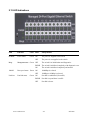
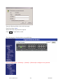
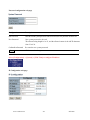
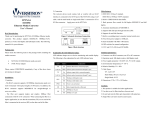
SG71090
24-Port 10/100/1000Base
Modular Pick-a-Port Switch
with Management &
100/1000Base SFP support
Installation Guide
v2.0
© January 2013
VERSITRON, Inc.
83 Albe Drive / Suite C
Newark, DE 19702
www.versitron.com
www.versitron.com
-1-
SG71090
PROPRIETARY DATA
All data in this manual is proprietary and may not be disclosed,
used or duplicated, for procurement or manufacturing purposes,
without prior written permission by VERSITRON.
VERSITRON LIFETIME WARRANTY
All VERSITRON products are covered by a Lifetime Warranty against defects in materials and
workmanship. This coverage is applicable to the original purchaser and is not transferable.
We repair, or at our option, replace parts/products that, during normal usage and operation, are proven
to be defective during the time you own the products, provided that said products and parts are still
manufactured and/or available. Such repair/replacement is subsequent to receipt of your product at
our facility and our diagnostic evaluation and review of the unit. Advance replacements are not
provided as part of the warranty coverage.
This warranty does not cover damage to products caused by misuse, mishandling, power surges,
accident, improper installation, neglect, alteration, improper maintenance, or other causes which are
not normal and customary applications of the products and for which they were not intended. No
other warranty is expressed or implied, and VERSITRON is not liable for direct, indirect, incidental
or consequential damages or losses.
In the unlikely event a warranty issue should arise, simply contact us at 302-894-0699 or
1-800-537-2296 or via email at [email protected] to obtain a Return Material Authorization
(RMA) number, along with instructions for returning your product.
www.versitron.com
-2-
SG71090
The information contained in this document is subject to change without prior notice.
Copyright (C) All Rights Reserved.
TRADEMARKS
Ethernet is a registered trademark of Xerox Corp.
FCC NOTICE
This device complies with Part 15 of the FCC Rules. Operation is subject to the following two conditions: (1)
This device may not cause harmful interference, and (2) This device must accept any interference received,
including the interference that may cause undesired operation.
CE NOTICE
Marking by the
symbol indicates compliance of this equipment to the EMC directive of the European
Community. Such marking is indicative that this equipment meets or exceeds the following technical
standards:
EMC Class A
EN55022:2006/A1:2007
EN61000-3-2:2006
EN61000-3-3:1995/A1:2001/A2:2005 Class A
EN 55024:1998/A1:2001/A2:2003
IEC 61000-4-2:2001
IEC 61000-4-3:2002/A1:2002
IEC 61000-4-4:2004
IEC 61000-4-5:2001
IEC 61000-4-6:2003
IEC 61000-4-8:2001
IEC 61000-4-11:2001
www.versitron.com
-3-
SG71090
Table of Contents
1. Introduction......................................................................................................................................................5
1.1 Features ................................................................................................................................. 6
1.2 Product Panels....................................................................................................................... 8
1.3 Optional Modules ................................................................................................................... 8
1.3.1 Optional Module Table ...................................................................................................... 11
1.4 LED Indicators ..................................................................................................................... 11
1.5 Specifications ....................................................................................................................... 11
2. Installation......................................................................................................................................................14
2.1 Unpacking ............................................................................................................................ 14
2.2 Safety Preautions................................................................................................................. 14
2.3 Installing Modules ................................................................................................................ 15
2.4 Removing the Modules ........................................................................................................ 16
2.5 Mounting the Switch............................................................................................................. 17
2.6 Applying AC Power ............................................................................................................ 18
2.7 Applying DC Power ............................................................................................................ 19
2.8 Reset Button ........................................................................................................................ 20
2.9 Making UTP Connections .................................................................................................... 20
2.10 Making SFP Fiber Connections ......................................................................................... 21
2.11 Making Fixed Duplex Fiber Connections ........................................................................... 22
2.12 Making Fixed Bi-Di (Bi-Directional) Fiber Connections ...................................................... 23
2.13 LED Indications .................................................................................................................. 25
2.14 Making Console Connection .............................................................................................. 26
3. Managing the Switch.....................................................................................................................................27
3.1 IP Address & Password ....................................................................................................... 27
3.2 Configuring IP Address & Password via Web Interface ....................................................... 27
3.3 Configuring IP Address & Password via console and telnet ................................................ 30
3.4 Reference Manuals for Web, Console, Telnet Management ............................................... 31
3.5 Configuration for SNMP Management ................................................................................. 31
3.6 SNMP MIBs ......................................................................................................................... 33
www.versitron.com
-4-
SG71090
1. Introduction
The SG71090 24-port Switch is a standard L2 switch that meets all IEEE 802.3/u/x/z Gigabit, Fast Ethernet
specifications. The switch provides three 8-port modular slots, each capable of accommodating one 8-port
module. A variety of modules are available, including 10/100/1000M copper, 100/1000M fiber optic SFP,
Copper and fiber optic SFP combination, and Fast Ethernet fiber optic modules. Different modules can be
installed to create flexibility within your network. The SG71090 automatically detects the types of modules
installed and configures the modules automatically. With a variety of modules and flexibility of installation, the
SG71090 can meet most network requirements.
The SG71090 supports Telnet CLI, Web GUI, SNMP and console management for switch stack management.
The network administrator can log into the switch to monitor and configure port operating mode, Quality of
Service, and powerful L2 switching functions such as VLAN, IGMP, RSTP, etc. In addition, the switch also
features powerful security functions such as SSH, HTTPS, IEEE 802.1x & MAC-based authentication, and
ACL control to make them suitable for office core applications.
The following image shows the SG71090 without modules installed.
Model Definition
Model
Power Input
Power connector
SG71090
AC 100 ~ 240V
IEC320
SG71090-DC
DC +48V
Screw terminals
www.versitron.com
-5-
SG71090
1.1 Features
z Fully modular design with three 8-port module slots supporting Gigabit and Fast Ethernet
z A variety of optional modules are available including Gigabit copper, Gigabit fiber, Gigabit mix of copper
and fiber, and Fast Ethernet fiber
z The copper ports support 10/100/1000Mbps auto-negotiation and auto-MDI/MDI-X detection
z The SFP ports can support both 100Mbps and Gigabit Ethernet SFP fiber optic SFP modules
z Support connectivity for Fast Ethernet fiber, 100BASE-FX with SC/ST/BiDi/ transceivers
z Flexible installation with any combination of different modules
z Provides Gigabit full wire speed forwarding
z Supports power saving mode when port link is down or for different RJ-45 cable lengths
z Supports 802.3x flow control for full-duplex and backpressure for half-duplex
z Supports console and in-band Web/Telnet/SSH/HTTPS/SNMP interfaces for switch management
z Supports configurable maximum frame length from 1518 up to 9600 jumbo frame
z Supports port-based ,802.1Q tag-based VLAN and private VLAN
z Provides QoS function
z Supports port bandwidth control for ingress and egress
z Supports packets storm control function for broadcast, unicast and multicast
z Supports MAC address learning, ageing and filtering control
z Supports LACP port link aggregation
z Supports IEEE 802.1d, 802.1w, 802.1s STP (Spanning Tree Protocol), RSTP, MSTP
z Provides port mirroring function
z Provides IP Multicasting with IGMP Snooping function
z Supports DHCP client for dynamic IP configuration
z Supports 802.1X port-based radius authentication for access security
z Provides ACL filtering function
z Provides port data rate control function
z Supports SNTP Client
z Supports LLDP
z Provides SNMP v1/v2C/v3 agent and event trap function
z Supports Configuration download and upload
z 19” rack mountable
z Both AC powered and DC powered models are available
www.versitron.com
-6-
SG71090
Management Features:
z Port Control
- Port Speed/Duplex Mode/Flow Control/Power saving configuration
- Port frame size control (Jumbo frame support)
z QoS
- Traffic Classification up to 4 active priorities
- Port QoS configuration
- QoS Control List for policy rules
- Port bandwidth control for ingress and egress
- Storm Control for UC, MC and BC
z Layer2
- Auto MAC address learning and ageing
- Static MAC address filtering
- Port-based and 802.1Q Tag-based VLAN
- Link Aggregation - LACP
- Rapid Spanning tree - RSTP
- Port Mirroring
- IGMP snooping
- DHCP client for IP configuration
z Security features
- Access Control List for L2/L3 protocol filtering, ingress rate limit, port copy
- Port Access Control based on IEEE 802.1X
z Management
- Web management
- Console CLI
- Telnet CLI
- Software Download via Web
- SNTP Client
- SNMP v1/v2c Agent
- SSH v2 & HTTPS
- Restore to default configuration
- Configuration download and upload
- System syslog
z SNMP MIBs
www.versitron.com
-7-
SG71090
1.2 Product Panels
The following figure illustrates the front panel and rear panel of the SG71090:
Model
Front Panel
Rear Panel (Power Input)
SG71090
SG71090-DC
1.3 Optional Modules
Module Part No.
Image
Specifications
SG71890
z 8 10/100/1000 copper ports
z 8 RJ-45 jacks
SG71896
z 8-port 100/1000 SFP slots
z Supports standard 100M or
1000M fiber optic SFP
modules
www.versitron.com
-8-
SG71090
SG71896-44
z 4 10/100/1000 copper ports
with RJ-45 connectors
z 4 dual-speed SFP slots support
standard 100M or 1000M fiber
optic SFP modules
SG71894
z 8 fixed 100M fiber ports
SG71895
z 8 duplex SC connectors
z Options:
SG71894: MMF 2km
SG71895: SMF 20km
SG71894-26
z 6 fixed 100M fiber ports with 6
SG71895-26
duplex SC connectors
z 2 10/100/1000 copper ports
with RJ-45 connectors
z Fiber options:
SG71894-26: MMF 2km
SG71895-26: SMF 20km
SG71893
z 8 fixed 100M fiber ports
z 8 duplex ST connectors
z MMF 2km
SG71893-26
z 6 fixed 100M fiber ports with 6
duplex ST connectors
z 2 10/100/1000 copper ports
with RJ-45 connectors
www.versitron.com
-9-
SG71090
SG71895-SFA
z 8 fixed 100M fiber ports with
SG71895-SFB
SC connectors
z Full-Duplex Bi-directional
communication over a
single-fiber
z Options:
SG71895-SFA:
Tx: 1310nm, Rx: 1550nm
SG71895-SFB:
Tx: 1550nm, Rx: 1310nm
z SMF 20km
SG71895-26SFA
z 6 fixed 100M fiber ports with
SG71895-26SFB
SC connectors
z 2 10/100/1000 copper ports
with RJ-45 connectors
z Full-Duplex Bi-directional
communication over a
single-fiber
z Options:
SG71895-26SFA:
Tx: 1310nm, Rx: 1550nm
SG71895-26SFB:
Tx: 1550nm, Rx: 1310nm
z SMF 20km
www.versitron.com
-10-
SG71090
1.3.1 Optional Module Table
Module Part No.
10/100/1000M Copper ports
SG71890
100/1000M pluggable SFP
Fixed 100M Fiber
8 RJ-45
SG71896
8 SFP
SG71896-44
4 RJ-45
4 SFP
SG71893
8 ST for MMF 2km
SG71894
8 SC for MMF 2km
SG71895
8 SC for SMF 20km
SG71895-SFA
8 Bi-Di SC
SG71895-SFB
for single SMF 20km
SG71895-26
2 RJ-45
6 SC for SMF 20km
SG71894-26
2 RJ-45
6 SC for MMF 2km
SG71893-26
2 RJ-45
6 ST for MMF 2km
SG71895-26SFA
2 RJ-45
6 Bi-Di SC
SG71895-26SFB
for single SMF 20km
1.4 LED Indicators
LED
Function
POWER
Power status
Mngt
Management status
1000M
Port speed 1000Mbps status
Link/Act.
Port link and activity status (Port 1 – Port 24)
1.5 Specifications
10/100/1000 Copper Ports
Compliance
IEEE 802.3 10Base-T, IEEE 802.3u 100Base-TX, IEEE 802.3u 1000Base-T
Connectors
Shielded RJ-45 connectors
Pin assignments
Auto MDI/MDI-X detection
Configuration
Auto-negotiation or software control
Transmission rate
10Mbps, 100Mbps, 1000Mbps
Duplex support
Full/Half duplex
Network cable
Cat.5 UTP
www.versitron.com
-11-
SG71090
Dual-speed SFP Slots
Compliance
IEEE 802.3z 1000BASE-SX/LX (mini-GBIC)
IEEE 802.3u 100BASE-FX
Connectors
SFP slot supports 100M and 1000M fiber optic SFP modules
Configuration options
Auto-negotiation 1000Mbps Full duplex
Forced 100Mbps Full duplex
(Software configurable)
Network cables
MMF 50/125μm 60/125μm, SMF 9/125μm
Eye safety
IEC 825 compliant
Fixed 100M Fiber Ports
Compliance
IEEE 802.3u 100BASE-FX
Connector options
Duplex SC for multimode fiber
Duplex SC for single mode fiber
Duplex ST for multimode fiber
Bi-Di SC for single SM fiber
Configuration
100Mbps, full duplex
Network cables
MMF 50/125μm 60/125μm, SMF 9/125μm
Eye safety
IEC 825 compliant
Console Port
Interface
RS-232, DTE type
Connector
9-pin D-sub
Switch Functions
MAC Addresses Table
8K entries
Forwarding & filtering
Non-blocking, full wire speed
Switching technology
Store and forward
Maximum packet length 9600 bytes (Jumbo frame support)
Flow control
IEEE 802.3x pause frame base for full duplex operation
Back pressure for half duplex operation
VLAN function
Port-based VLAN and IEEE 802.1Q Tag-based VLAN
VLAN support
4096 VLANs (IEEE 802.1Q)
Aggregation
LACP Port link aggregation (port trunking)
www.versitron.com
-12-
SG71090
QoS function
Ethernet type, IP-based, DSCP, TOS-based, VID-based, VLAN Tag-based packet
classification
Port rate control, storm control
Port Mirroring
Mirror received frames to a sniffer port
AC Power Input (SG71090)
Interface
IEC320 receptacle
Operating Input Voltages 100 ~ 240VAC, 50/60Hz, 1.7A
Power Consumption
40W max.
DC Power Input (sg71090-DC
Interfaces
Screw-type terminal block
Operating Input Voltages +40 ~ +72VDC
Power Consumption
40W max.
DC Power Output
Operating Output Voltage +5VDC, 13A
Mechanical
Dimension (base)
17.44 x 9.65 x 1.69 Inches (W x D x H) (443 x 245 x 43 mm)
Housing
Enclosed metal
Mounting
Desktop mounting, 19” rack mounting
Environmental
Operating Temperature Typical -5oC ~ +50oC
Storage Temperature
-25oC ~ +85oC
Relative Humidity
10% ~ 90% non-condensing
Electrical Approvals
FCC
Part 15 rule Class A
CE
EMC, CISPR22 Class A
Safety
LVD, IEC60950-1
www.versitron.com
-13-
SG71090
2. Installation
2.1 Unpacking
The product package contains:
z SG71090
z One AC power cord (with SG71090)
z One 19” rack mounting kit
2.2 Safety Precautions
To reduce the risk of bodily injury, electrical shock, fire and damage to the product, observe the following
precautions.
z
Do not service any product except as explained in your system documentation.
z
Opening or removing covers may expose you to electrical shock.
z
Only a trained service technician should service components inside the device.
z
If any of the following conditions occur, unplug the product from the electrical outlet and replace the part
or contact VERSITRON:
- The power cable, extension cable, or plug is damaged.
- An object has fallen into the product.
- The product has been exposed to water.
- The product has been dropped or damaged.
- The product does not operate correctly when you follow the operating instructions.
z
Do not push any objects into the openings of your system. Doing so can cause fire or electric shock by
shorting out interior components.
z
Operate the product only from the type of external power source indicated on the electrical ratings label. If
you are not sure of the type of power source required, contact VERSITRON or local power company.
www.versitron.com
-14-
SG71090
2.3 Installing Modules
The steps to install a module are as follows:
1. Unscrew the screws and remove the cover of the module slot. (Do not discard the screws.)
2. Insert the module into the slot until it is seated into the internal slot connector properly.
3. Push in the screw tabs and install the screws
4. Tighten the screws to secure the module to the switch chassis.
www.versitron.com
-15-
SG71090
2.4 Removing the Modules
The steps to remove an installed module are as follows:
1. Remove the screws securing the module to the switch chassis:
2. Slide out the screw tabs:
3. Use the screw tabs as handles to slide the module out from the internal slot connector:
4. Remove the module from the slot.
www.versitron.com
-16-
SG71090
2.5 Mounting the SG71090
Desktop Mounting
The SG71090 can be mounted on a desktop or shelf. Make sure that there is proper heat dissipation from and
adequate ventilation around the device. Do not place heavy objects on the device.
Rack Mounting
Two 19-inch rack mounting brackets are supplied for 19-inch rack mounting.
The steps to mount the SG71090 onto a 19-inch rack are:
1. Turn the power to the switch off.
2. Install two brackets with supplied screws onto the switch as shown below:
SG71090 with rack mounting brackets installed
www.versitron.com
-17-
SG71090
2. Mount the SG71090 securely onto 19-inch rack with rack screws (not provided):
3. Apply power to the switch.
2.6 Applying AC Power – SG71090
1. Connect the AC power cord to the SG71090 before plugging it into the AC power outlet.
2. Connect the SC power cord to the AC power outlet.
SG71090 AC Power Connector
AC power input specifications
Connector: IEC320 type
Power Rating: 100 ~ 240VAC, 50/60Hz
Voltage Range: 90 ~ 264VAC
Frequency: 47 ~ 63 Hz
Power Consumption: 40W max.
www.versitron.com
-18-
SG71090
2.7 Applying DC Power – SG71090-DC
The SG71090-DC power connector is shown below:
SG71090-DC Power Connector
DC power input specifications
Receptacle: Screw-type terminal block
Operating Voltages: +40 ~ +72VDC
Power Consumption: 40W max.
Contacts
VDC+ input
VDC- input
Ground
www.versitron.com
-19-
SG71090
2.8 Reset Button
The reset button is used to perform a reset of the switch. It can be used for diagnostic purpose or if the network
performance has an issue. The button can also be used to restore the software configuration settings to factory
default values. The operations are as follows:
Operation
Function
Press the button during system boot-up and release
Restore factory default settings
it after boot-up. The boot-up takes about 17 seconds
and ends with LED diagnostics.
Press the button and release during switch operation
Re-boot the switch unit
2.9 Making UTP Connections
The 10/100/1000 RJ-45 copper ports support the following connection types and distances:
Network Cables
10BASE-T:
2-pair UTP Cat. 3, 4, 5, EIA/TIA-568B 100-ohm
100BASE-TX: 2-pair UTP Cat. 5, EIA/TIA-568B 100-ohm
1000BASE-T: 4-pair UTP Cat. 5 or higher (Cat.5e is recommended), EIA/TIA-568B 100-ohm
Link distance: Up to 100 meters
Auto MDI/MDI-X Function
This function allows the port to auto-detect the twisted-pair signals and adapts itself to form a valid MDI to
MDI-X connection with the remote connected device automatically. No matter a straight through cable or
crossover cable are connected, the ports can sense the receiving pair automatically and configure themselves to
match the rule for MDI to MDI-X connection. It simplifies the cable installation.
www.versitron.com
-20-
SG71090
Auto-negotiation Function
The ports are featured with auto-negotiation function and full capability to support connection to any Ethernet
devices. The port performs a negotiation process for the speed and duplex configuration with the connected
device automatically each time a link is being established. If the connected device is also auto-negotiation
capable, both devices will configure to the best performance option after negotiation process. If the connected
device is incapable in auto-negotiation, the switch will sense the speed and use half duplex for the connection.
Port Configuration Management
For making proper connection to an auto-negotiation INCAPABLE device, it is suggested to use the port
control function via the software management to set forced mode and specify speed and duplex mode which
match the configuration used by the connected device.
2.10 Making Fiber Optic SFP Connections
The dual-speed SFP slot must be populated with a fiber optic SFP module to make fiber connections. The fiber
optic SFP modules are sold separately. Please refer to Appendix A for a list of available VERSITRON SFP
modules.
The SFP slots can be populated with either 100Base or 1000Base, multi-mode or single-mode fiber optic SFP
modules. Therefore it is important to match the fiber type, communication speed, and wavelength of the device
connected on the other end of the fiber. If these criteria do not match, the SG71090 and the device on the other
end of the fiber will not communicate.
Installing a fiber optic SFP Module
To install an SFP module, the steps are as follows:
1. Turn off the power to the switch.
2. Insert the SFP module into an available SFP slot. Normally, a bail is provided with the module. Hold the
bail and insert the module
www.versitron.com
-21-
SG71090
3. Push the module into the slot until it is seated securely in the slot and then place the bail in lock position.
Connecting Fiber Cables
LC connectors are commonly equipped on most SFP. Identify the TX and RX connector before making the
cable connection. Plug in the cables as shown below. Make sure the RX-to-TX connection rule is followed
between two ends of the connected cable.
2.11 Making Fixed Duplex Fiber Connections
The following figure illustrates an example of a fixed duplex fiber port with duplex SC connectors:
A module with fixed duplex ST connectors is also available.
www.versitron.com
-22-
SG71090
Identify the TX and RX connector before making the cable connection. Plug in the cables as shown below.
Make sure the RX-to-TX connection rule is followed between two ends of the connected cable.
2.12 Making Fixed Bi-Di (Bi-Directional) Fiber Connections
The following figure illustrates an example of fixed Bi-Di (Bi-directional) fiber port with one SC connector.
www.versitron.com
-23-
SG71090
A Bi-Di port supports single fiber connection. It uses different optical wavelengths for transmitting and
receiving data as shown below:
www.versitron.com
-24-
SG71090
2.13 LED Indications
LED
Function
Color State
Interpretation
POWER
Power status
Green ON
The power is supplied to the switch.
OFF
Mngt
Management status Green OFF
1000M
The switch is initialized completely with diagnostic error.
ON
The switch is initialized completely and normal.
Port speed status Green ON
Port link status
www.versitron.com
The switch is in initialization and diagnostics.
BLINK
OFF
Link/Act.
The power is not supplied to the switch.
Green ON
1000Mbps is selected
100Mbps or 10Mbps is selected.
Port link is established. (No traffic)
BLINK
Port link is up and there is traffic.
OFF
Port link is down.
-25-
SG71090
2.14 Making Console Connection
The console port is a DB9 connector. It serves as an RS-232 DTE port.
Pin Definitions
Pin 2
RXD
Pin 3
TXD
Pin 5
GND
Pin 1,4,6-9 NC
Use an RS-232 null modem cable without handshaking to connect the console port to a PC’s DB9 COM port as
follows:
Console Pins
COM Port Pins
Pin 2
RXD ----------------------------- Pin 3
TXD
Pin 3
TXD ----------------------------- Pin 2
RXD
Pin 5
GND ----------------------------- Pin 5
GND
Baud Rate Information
Baud rate: 115200
Data bits: 8
Parity: none
Stop bit: 1
Flow control: disabled
www.versitron.com
-26-
SG71090
3. Managing the Switch
The SG71090 provides the following methods to configure and monitor the switch:
z Making out of band management via RS-232 console port
z Making in-band management via telnet interface over TCP/IP network
z Making in-band management via web interface over TCP/IP network
z Making in-band SNMP management over TCP/IP network
3.1 IP Address & Password
The IP Address is an identification of the switch in a TCP/IP network. Each switch should be designated a new
and unique IP address in the network. The switch is shipped with the following factory default settings for
software management:
Default IP address of the switch: 192.168.0.2 / 255.255.255.0
Fixed Username: admin
No password
The switch uses local authentication instead of RADIUS authentication with factory defaults. No password is
required with the factory default. However, the password is used for local authentication in accessing the
switch via console, telnet and Http web-based interface. For security reasons, it is recommended that the
default settings for the switch be changed before deploying it to your network.
3.2 Configuring IP Address & Password via Web Interface
Start Web Browser
Start your browser software and enter the default IP address to which you want to connect. The IP address is
used as a URL for the browser software to search the device.
URL: http:/192.168.0.2/
Login to the switch
When the browser software connects to the switch successfully, a Login screen is provided for you to login to
the device as shown below:
www.versitron.com
-27-
SG71090
Enter the following default values in the login page:
Fixed User Name: admin
Default password: No password is required.
Click
OK
to login into the switch.
The following page is displayed after a successful login:
Select [Configuration] -> [Security] -> [Switch] -> [Password] to configure a new password
www.versitron.com
-28-
SG71090
Password configuration web page
Configuration
Description
Old Password
Enter the current system password. If this is incorrect, the new password will not be set.
New Password
New system password to be used
The allowed string length is 0 to 31, and the allowed content is the ASCII characters
from 32 to 126.
Confirm New Password
Save
Re-enter the new system password.
Click to save the changes.
Select [Configuration] -> [System] -> [IP & Time] to configure IP address
IP Configuration web page
www.versitron.com
-29-
SG71090
Configuration
Description
DHCP Client
Enable the DHCP client by checking this box.
IP Address
Provide the IP address of this switch unit.
IP Mask
Provide the IP mask of this switch unit.
IP Router
Provide the IP address of the default router for this switch unit.
VLAN ID
Provide the managed VLAN ID. The allowed range is 1 through 4095.
SNTP Server
Provide the IP address of the SNTP Server.
Save
Click to save the changes.
Reset
Click to undo any changes made locally and revert to previously saved values.
Renew
Click to renew DHCP. This button is only available if DHCP is enabled.
Note:
1. If DHCP fails and the configured IP address is zero, DHCP will retry. If DHCP fails and the configured IP
address is non-zero, DHCP will stop and the configured IP settings will be used. The DHCP client will
announce the configured System Name as hostname to provide DNS lookup.
2. The IP addresses should be in dotted decimal notation.
3.3 Configuring IP Address & Password via console and telnet
[Password] setting command is in System command group.
>System password <password>↵
Parameters:
<password>: The allowed password string length is 0 to 31, and the allowed content is the ASCII
characters from 32 to 126.
[IP] command group is used to configure the switch’s IP settings. The command syntax is:
>IP DHCP [enable|disable]
>IP Setup [<ip_addr>] [<ip_mask>] [<ip_router>] [<vid>]
Parameters:
<ip_addr>: IP address (a.b.c.d), default: Show IP address
<ip_mask>: IP subnet mask (a.b.c.d), default: Show IP mask
<ip_router>: IP router (a.b.c.d), default: Show IP router
<vid>: VLAN ID (1-4095), default: Show VLAN ID
www.versitron.com
-30-
SG71090
3.4 Reference Manuals for Web, Console, Telnet Management
The following operation manuals are also provided separately for Console, Telnet and Web management:
• SG71090 - Telnet & Console Management Manual
• SG71090 – Web –Based Management Manual
The manuals describe the detailed commands and information.
3.5 Configuration for SNMP Management
The switch supports SNMP v1, SNMP v2c, and SNMP v3 management. Make sure the related settings are
well-configured for the switch before you start the SNMP management from an SNMP manager.
Using Telnet Interface
The following commands are available for telnet SNMP to configure SNMP-related settings:
>SNMP Configuration
>SNMP Mode [enable|disable]
>SNMP Version [1|2c|3]
>SNMP Read Community [<community>]
>SNMP Write Community [<community>]
>SNMP Trap Mode [enable|disable]
>SNMP Trap Version [1|2c|3]
>SNMP Trap Community [<community>]
>SNMP Trap Destination [<ip_addr_string>]
>SNMP Trap Authentication Failure [enable|disable]
>SNMP Trap Link-up [enable|disable]
>SNMP Trap Inform Mode [enable|disable]
>SNMP Trap Inform Timeout [<timeout>]
>SNMP Trap Inform Retry Times [<retries>]
>SNMP Trap Probe Security Engine ID [enable|disable]
>SNMP Trap Security Engine ID [<engineid>]
>SNMP Trap Security Name [<security_name>]
>SNMP Engine ID [<engineid>]
>SNMP Community Add <community> [<ip_addr>] [<ip_mask>]
www.versitron.com
-31-
SG71090
>SNMP Community Delete <index>
>SNMP Community Lookup [<index>]
>SNMP User Add <engineid> <user_name> [MD5|SHA] [<auth_password>] [DES] [<priv_password>]
>SNMP User Delete <index>
>SNMP User Changekey <engineid> <user_name> <auth_password> [<priv_password>]
>SNMP User Lookup [<index>]
>SNMP Group Add <security_model> <security_name> <group_name>
>SNMP Group Delete <index>
>SNMP Group Lookup [<index>]
>SNMP View Add <view_name> [included|excluded] <oid_subtree>
>SNMP View Delete <index>
>SNMP View Lookup [<index>]
>SNMP Access Add <group_name> <security_model> <security_level> [<read_view_name>] [<write_view_name>]
>SNMP Access Delete <index>
>SNMP Access Lookup [<index>]
Using Web Interface
The commands support configuration for:
-
Basic system configuration for SNMP v1 and SNMP v2c
-
Basic system configuration for SNMP v1 trap, SNMP v2c trap and SNMP v3 trap
-
Communities that permit to access to SNMPv3 agent
-
USM (User-based Security Model) user table for SNMPv3
-
VACM (View-based Access Control Model) Viewer table for SNMPv3
-
Group table for SNMPv3
-
Accesses group table for SNMPv3
www.versitron.com
-32-
SG71090
3.6 SNMP MIBs
The switch provides the following SNMP MIBs:
- RFC 1213 MIB II
- RFC 3635 Ethernet-like MIB
- RFC 4188 Bridge MIB
- RFC 3636 802.3 Medium Attachment Units (MAUs) MIB
- RFC 2863 Interface Group MIB using SMI v2
- RFC 4133 Entity MIB v3
- RFC 2933 IGMP MIB
- IEEE 802.3AB LLDP MIB
One product MIB file is also available in the product CD for SNMP manager software.
www.versitron.com
-33-
SG71090
Appendix A – Duplex Fiber Modules
Model
Speed (Mbps)
Wavelength
Media
Distance
FEMM
100
850nm
MMF
2km
LC
FE2MM
100
1310nm
MMF
2km
FE10SM
100
1310nm
SMF
GBMM
1000
850nm
GB2MM
1000
1310nm
GB10SM
1000
1310nm
GB20SM
1000
1310nm
SMF
GB40SM
1000
1550nm
GB70SM
1000
GB100SM
1000
www.versitron.com
RX Sens
Temp
-10 ~ -4
< -24
0 to 70° C
LC
-20 ~ -4
< -31
0 to 70° C
10km
LC
-15 ~ -8
< -34
0 to 70° C
MMF
220m(62.5µ) / 550m(50µ)
LC
-9.5 ~ -4
< -18
0 to 70° C
MMF
2km
LC
-9 ~ -1
< -19
0 to 70° C
LC
-9.5 ~ -3
< -20
0 to 70° C
20km
LC
-4 ~ +1
< -24
0 to 70° C
SMF
40km
LC
-4 ~ +1
< -24
0 to 70° C
1550nm
SMF
70km
LC
0 ~ +5
< -24
0 to 70° C
1550nm
SMF
100km
LC
0 ~ +5
< -30
0 to 70° C
MMF / SMF 550m (MM) / 10km (SM)
-34-
Connector TX Power
SG71090
Appendix A – Single Fiber Modules
Model
Speed (Mbps)
GB10SFA
1000
Wavelength
Media
Distance
Connector TX Power
RX Sens
Temp
SMF
10km
LC
-3 ~ -9
< -21
0 to 70° C
SMF
10km
LC
-3 ~ -9
< -21
0 to 70° C
SMF
20km
LC
-3 ~ -8
< -23
0 to 70° C
SMF
20km
LC
-3 ~ -8
< -23
0 to 70° C
SMF
40km
LC
-3 ~ +2
< -23
0 to 70° C
SMF
40km
LC
-3 ~ +2
< -23
0 to 70° C
SMF
60km
LC
0 ~ +5
< -24
0 to 70° C
SMF
60km
LC
-2 ~ +4
< -25
0 to 70° C
SMF
80km
LC
-2 ~ +3
< -26
0 to 70° C
SMF
80km
LC
-2 ~ +3
< -26
0 to 70° C
Tx: 1310nm
Rx: 1550nm
Tx: 1550nm
GB10SFB
1000
Rx: 1310nm
Tx: 1310nm
GB20SFA
1000
Rx: 1550nm
Tx: 1550nm
GB20SFB
1000
Rx: 1310nm
Tx: 1310nm
GB40SFA
1000
Rx: 1550nm
Tx: 1550nm
GB40SFB
1000
Rx: 1310nm
Tx: 1310nm
GB60SFA
1000
Rx: 1550nm
Tx: 1550nm
GB60SFB
1000
Rx: 1310nm
Tx: 1310nm
GB80SFA
1000
Rx: 1550nm
Tx: 1550nm
GB80SFB
1000
Rx: 1310nm
Note: CWDM (Coarse-Wavelength-Division-Multiplexing) modules are also available upon request.
www.versitron.com
-35-
SG71090