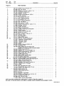
1
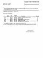
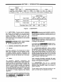
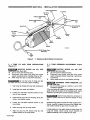
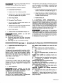
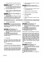
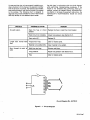
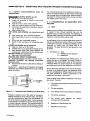
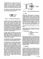
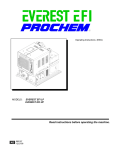
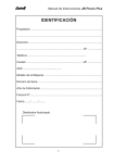
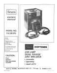
Dec.1987
IMPORTANT
Read
and
understand
the
entire
FORM: OM-~18 044
Effective With Serial No. JH318063
______________
manual, with special emphasis on
the safety material throughout the manual, before
contents of this
installing, operating,
or
maintaining this equip
ment. This unit and these instructions
are
for
use
only by persons trained and experienced in the safe
operation of welding equipment. Do not allow un
trained persons to install, operate, or maintain this
unit. Contact your distributor if you do not fully
understand these instructions.
1fl~
0~
OWNERS
MANUAL
AUTO ARC
MILLER ELECTRIC MFG. Co.
718 S. BOUNDS ST. P.O. Box 1079
APPLETON, WI 54972 USA
ADDITIONAL COPY PRICE 50 CENTS
NWSA CODE NO. 4579
PRINTED IN U.S.A.
MODEL
AUTO ARC
AASW 1510M
ONE YEAR LIMITED WARRANTY
Miller Electric Mfg. Co. warrants to the buyer
for personal,
purchases this Auto Arc Welder (Welder)
that this Welder
family or household purposes (Consumer)
will be free from defects in material and workmanship for a
period of one year from the date of purchase. This warranty
covers only the original purchaser of this Welder. Miller Electric
does not authorize any party, including its authorized
COVERAGE
-
who
~~
distributors,
to ofter any other
warranty
on
behalf of Miller
Upon expiration of the warranty period, Miller Electric
shall have no further liability related to the Welder, except on
warranty claims made during the warranty period.
Electric.
,,4~
THIS WARRANTY IS OFFERED IN LIEU OF ANY OTHER
EXPRESS WARRANTY; AND, EXCEPT TO THE EXTENT
PROHIBITED BY APPLICABLE LAW, THE DURATION OF
IMPLIED
ALL
WARRANTIES, INCLUDING BUT NOT
LIMITED TO THE IMPLIED WARRANTIES OF MERCHAN-
TABILITY AND FITNESS FOR A PARTICULAR PURPOSE, IS
LIMITED TO THE DURATION OF THIS WARRANTY,
~
c~.
Some states do not allow limitations on how long an implied
warranty lasts, so the above limitation may not apply to you.
This warranty gives you specific legal rights, and you may also
have other
rights which
vary from state to state.
REMEDY FOR DEFECTIVE WELDER
Upon receipt of any
defective Welder, Miller Electric will, at its option, repair or
replace the defective Welder at its expense, refund or credit
-
purchase price (less
depreciation based on ac
cost of repair or
replacement at an approved Miller Electric warranty station,
provided that the purchaser of that Welder has followed the
procedure for obtaining warranty performance set forth below.
The Welder so repaired or used as a replacement will be Ship
ped to the purchaser of the defective Welder, with transporta
tion charges prepaid to any destination in the continental
United States (transportation charges on shipments to Alaska
or Hawaii will be paid only to the nearest port of export).
the
tual use),
THE
or
reasonable
reimburse the Consumer for the
PURCHASERS
REMEDIES
FOR
A
DEFECTIVE
WELDER, TO THE EXTENT PERMITTED BY APPLICABLE
LAW, ARE LIMITED TO THE REMEDY PROVIDED BY THIS
WARRANTY:
AND, TO THE EXTENT ENFORCEABLE
UNDER APPLICABLE LAW, MILLER ELECTRIC SHALL IN
NO EVENT BE LIABLE FOR CONSEQUENTIAL, INCIDENTAL
OR SPECIAL DAMAGES ARISING OUT OF THE USE OF, OR
INABILITY TO USE. THE WELDER, WHETHER BASED ON
BREACH OF THIS WARRANTY, MILLER ELECTRICS
NEGLIGENCE OR OTHER TORT, OR ON ANY THEORY OF
STRICT LIABILITY.
specified below, Millers warranty does not apply
to components having normal useful life of lebs than one (1)
year, such as spot welder tips, relay and contactor points,
parts that come in contact with the welding wire including
Except
~
as
nozzles and nozzle insulators where failure doer not result from
defect in workmanship
or
Some
states do not
allow the exclusion
sequential or incidental damages,
not apply to you.
so
or
limitation of
con
the above limitations may
material.
PROCEDURE FOR OBTAINING WARRANTY PERFORMANCE
~
Miller shall be
honor warranty claims on war
ranted Equipment in the event of failure resulting from a defect
within the following periods from the date of delivery of Equipment to
~
the
required
original
to
user:
as
defect. The
1. Arc welders, power sources, and components
2
Original
main power rectifiers
(labor
1 year
-
1 year
3 years
4.
welding guns, feeder/guns and plasma torches... ~
60 days
Replacement or repair parts, exclusive of labor
..
WHAT IS NOT COVERED
known, the
pur
period,
purchaser
return
must
then, within the
one
the Welder to Miller Electric at the
year warranty
following
ad-
dress:
-
This warranty does
not
extend
Miller Electric
Mfg Co
718 South Bounds Street
P.O. Box 1079
Appleton, Wisconsin 54912
Welder
subjected to misuse, neglect, accident, or in
warranty repair by anyone except Miller Electric, Further, this
warranty only extends to those purchasing the Welder for personal, family or household purposes. Commercial and industrial users are given a different warranty.
to any
any defect in a Welder becomes
only)
3. All
~Q
As soon
chaser of the Welder must, within thirty ~30) days, notify an
approved Warranty Station or Miller Electric in writing of the
All
transportation charges
be prepaid.
to
Warranty Station
or
Miller Electric
must
e
ERRATA SHEET
After this manual
to data
was
appearing
printed,
AMEN DMENT TO SECTION 9
Amend P~rts List
Dia.
as
Part
No.
13-26
13-
Si
087 182
024 253
13-39
13-41
13-45
Ti
**First
equipment design occurred.
This sheet lists
exceptions
PARTS LIST
follows:
Mkgs.
12-4
refinements In
later in this manual.
Replaced
With
023
011
011
+095
026
099
024 254
+095 347
605 370
094 499
659
746
292
345
763
469
Description
Quantity
HARNESS, wiring-switch (Effw/JK727617)
1
SWITCH, control
TOGGLE, switch
TRANSFORMER, pwr-main (Fig 9-2)
TUBING, No. 7 x 2.500
CORD SET, pwr i25V 16 ga 3/c lOft
1
digit represents page no digits following dash represent item no.
+When ordering a component originally displaying a precautionary label,
1
1
3
1
-
the label should also be ordered.
BE SURE TO PROVIDE MODEL AND SERIAL NUMBER WHEN ORDERING REPLACEMENT PARTS.
Th~ ~J~'
~
TABLE OF CONTENTS
Page No.
Section No.
SECTION 1
SAFETY RULES FOR OPERATION OF PORTABLE RESISTANCE
-
SPOT WELDING EQUIPMENT
1
1
1
1
1
-
-
-
-
-
Introduction
Installation
1
2.
3.
Safety
1
4.
Personal Safety
Burn Prevention
Fumes
Fire Prevention
Protection Of Others
Cords
Hoses
Maintenance
Standardslndex
1.
5.
1 -6.
1
1
-
-
7.
8.
1-9.
1-10.
1 -11.
1-12.
SECTION 2
2
-
-
-
3
3
-
-
-
-
4
4
-
-
-
-
-
1
1
1
INTRODUCTION
3
3
3
4.
1.
2.
3.
4.
1.
2.
3.
1.
SECTION 6
-
1
Receiving-Handling
Description
-
6
1
3.
5-2.
3.
5
6
1
3
SECTION 5
5
1
General Information And Safety
SECTION 4
4
1
DutyCycle
SECTION 3
3
3
1
2.~
2-1.
2
2
-.
1
Devices
-
INSTALLATION
Tong Tip And Tong Installation
Tong Pressure Adjustment
Hand Lever Adjustment
Electrical Input Connections
-
5
5
MAINTENANCE & TROUBLESHOOTING
Routine Maintenance
6
TipDressing
Troubleshooting
6
6
-
RESISTANCE SPOT WELDING PROCESS FUNDAMENTALS
1.
Safety Requirements
2.
Fundamentals Of Resistance
and Introduction
MaterialsToBeWelded
6
Testing
4.
5
5
6
6-3.
-
4
SEQUENCE OF OPERATION
Operator Controls
Spot Welding
Shutting Down
-
4
Procedures
Spot Welding
8
8
10
11
SAFETY RULES FOR OPERATION OF
______
PORTABLE RESISTANCE SPOT WELDING EQUIPMENT
SECTION 1
1
-
-
INTRODUCTION
The following safety rules
general safe practices which as a minimum should
employed when using resistance spot welding equip
1.
-
cover
be
ment.
from the surface, the area is adequately ventilated,
the operator wears an air respirator.
1
7. FIRE PREVENTION
Flying sparks can pass
through cracks, windows, doors, wall and floor open
ings, and along pipes.
-
Establishment of
an
safety consciousness
attitude of
is
necessary for the protection of personnel and property.
Do not install, operate, or maintain this equipment
before
reading this manual.
All equipment should be in
1
2. INSTALLATION
stalled by qualified personnel in conformance with local,
state, and federal codes.
-
-
1
-
DEVICES
3. SAFETY
-
Safety devices such
fuses should not be disconnected
PERSONAL SAFETY
or
as
shunted out.
-
4.
shut off power when
Always
leaving equipment
unat
tended.
near
the
equip
ment.
BURN
PREVENTION
long-sleeve shirt
gloves, hat, and
high top shoes. Button shirt collar, pocket flaps, and
sleeve cuffs to avoid entry of sparks.
-
5.
fire resistant
Wear
-
and cuff-less trousers in addition to
nondurable
with
treated
safety goggles
face shield for
Avoid oils
by sparks
or
materials
flame-retardent
should be retreated after each
wetting
glasses
or
cleaning.
with side shields. Use
severe exposure to
a
Do not weld where
dust, gas,
without
6.
flying sparks.
greases on clothing which could be ignited
and do not use flammable hair preparations.
as
tong tips
or
workpiece
wearing gloves.
FUMES
-
Severe
discomfort
or
illness
can
result from fumes and vapors produced by welding. Use
adequate ventilation as described in ANSI Z49.1.
After
may contain flammable
vapors (such as gasoline).
atmosphere
equipment rated capacity.
completion of work inspect area to
glowing embers, and flames.
ensure
it is free
1
8.
-
or each person in the
the operator must wear an air-supplied
Both must be used when beryllium is involv
exhaust ventilation must be used
well
respirator.
shields
or
OTHERS
-
Workers
or
should be
and
required
screens
to wear suitable eye
should permit circula
9. CORDS
Frequently inspect for wear, cracks,
damage. Immediately replace cords with excessive
ly worn or damaged insulation to avoid possibly lethal
-
-
and
shock from bared conductors. Keep cords dry, free of
oil and grease and protect from hot metal and sparks.
1 -10.
HOSES
On water cooled equipment examine
fittings regularly for leaks and loose connec
tions. Repair or replace leaky hoses and fittings. Do not
use tape to repair leaky hoses.
-
MAINTENANCE
materials that emit toxic fumes
removed
-
Remove
leaky
or
faulty
equipment from service immediately for repair. Keep
equipment clean and properly adjusted.
1-12. STANDARDS INDEX
1.
P~NSI Standard Z49.1 Safety
Cutting,
Society,
In Welding And
obtainable from the American Welding
550 Le Jeune Rd., P.O. Box 351040,
Miami, FL 33135.
2.
NFPA Standard 70-1978, National
Electrical
Code, obtainable from the National Fire Protec
tion Association, 470 Atlantic Avenue, Boston,
MA
coating is
OF
tion of air at floor level.
ed.
should not be heated unless the
or
protection. Booths
as
Metals coated with
PROTECTION
other persons adjacent to the welding area should be
protected by noncombustible or flame-resistant screens
Lead-, cadmium-, zinc-, mercury-, and beryllium- bear
ing and similar materials when welded may produce
harmful concentrations of toxic fumes. Adequate local
area as
liquid
Do not exceed the
1 -11.
-
or
hoses and
or
Do not handle hot metal such
1
shield.
Walls, ceilings, and floors near the work area should be
fire resistant or protected by fire resistant covers or
1
clothing is preferable to cotton because it is not
so readily ignited. Cotton clothing if used should be
chemically treated to reduce its combustibility. Clothing
Woolen
Wear
covers or
of sparks,
Disconnect provisions must be available
1
If combustibles are nearby, do not weld. Move work if
practicable to an area free of combustibles. If work can
not be moved, move combustibles to a safe location or
protect against ignition with suitable and snug-fitting
-
service of
or
-
shields.
Before installation, in
equipment, disconnect input
power and employ lockout/tagging procedures to pre
vent accidental turning on of power.
1
spection,
or
3.
02210.
OSHA
Safety And Health Standards, 29 CFR
1910, obtainable from the Superintendent of
118044
Page
1
4.
Documents, U.S. Government Printing Office,
Institute,
Washington, D.C. 20402.
10018.
ANSI Standard Z87.1 Safe Practices For Oc
cupation And Educational Eye And Face Protec
tion, obtainable from the American National
7.
Standard
Processes,
Protection
Standards Institute, 1430 Broadway, New York,
NY 10018.
Broadway,
51B,
New
Cutting
York,
And
NY
Welding
obtainable from the National Fire
Association, 470 Atlantic Avenue,
Boston, MA 02210.
8.
5.
NFPA
1430
For Mens
Standard
ANSI Standard
from the
obtainable
Toe
Footwear,
Safety
American National Standards Institute, 1430
NWSA booklet, Welding
Safety Bibliography,
Welding Supply
Street, Philadelphia, PA
obtainable from the National
Z41 .1
Association, 1900 Arch
19103.
Broadway, New York, NY 10018.
9.
6.
ANSI Standard Z49.2 Fire Prevention In The
ob
Use Of Cutting And Welding Processes,
tainable from the American National Standards
118044 Page2
Code for
Safety
in
Welding
Standard Wi 17.2-1974.
And
Cutting, CSA
SECTION 2
-
INTRODUCTION
Rated
Output
Voltage Input
50%
Open-
60 Hertz
Circuit
Single-Phase
Duty
Cycle
Voltage
110 Volts AC
1.5 Kva
1.6
Welder Dimensions Without Tongs
I
Height
6 in. 1152
I
Width
mm)I
3-1/4 in. (83
Weight
Length
mm)113
I
Ship
kg)126
lbs. (12
Net
in. (330 mm)
22 lbs. (10
kg)
AASW_1510M
12 in.
(305 mm)
6 in.
Tongs Length
(152 mm)
18 in.
(457 mm)
Secondary
110
Primary Volts
Short
Circuited
I
82
Primary Amps
Secondary Amps
Figure
2
-
1.
The duty cycle of a resistance
DUTY CYCLE
is
the
welder
percentage of a one minute period
spot
that a resistance spot welder can be operated without
causing overheating or damage to the unit. This
2
1.
-
5500
– 10%
-
resistance spot welder is rated at 50% duty cycle,
which means that it can be operated for thTrty seconds
L
70
60
4500
3600
Specifications
WARNING statements include installation, operation,
procedures or practices which if not
and maintenance
carefully followed could result in serious personal injury
or
loss of life.
CAUTION statements include installation, operation,
and maintenance procedures or practices which if not
carefully followed could result in minor personal injury
or damage to this equipment.
___________
out
of every minute.
s4..1U1ls]~W EXCEEDING
DUTY CYCLE RATING
damage the resistance spot welder.
Do not exceed 50% duty cycle.
will
A third signal word, IMPORTANT highlights instruc
tions which need special emphasis to obtain the most
_________
2
-
2. GENERAL INFORMATION AND SAFETY
A.
General
efficient operation of this equipment.
Before installing
3. RECEIVING-HANDLING
from around
material
clean
all
packing
equipment,
the unit, and carefully inspect for any damage that may
have occurred during shipment. Any claim for loss or
damage that may have occurred in transit must be filed
by the purchaser with the carrier. A copy of the bill
2
-
-
this
Information presented in this manual and
on
various
labels, tags, and plates on the unit pertains to equip
ment design, installation, operation, maintenance, and
troubleshooting which should be read, understood, and
followed for the safe and effective
use
of this
equip
B.
The
lading will
of
be furnished
quest if occasion
ment.
on re
requesting information concerning this equip
ment, it is essential that Model Description and Serial
Number of the equipment be supplied.
When
Safety
installation,
by the manufacturer
to file claim arises.
operation,
maintenance,
and
of resistance spot welding equipment
practices and procedures which ensure per
troubleshooting
requires
sonal safety and the safety of others. Therefore, this
equipment is to be installed, operated, and maintained
only by qtialifPed persons in accordance with this
manual and all applicable codes such as, but not limited
to, those listed at the end of Section 1
For Operation Of Portable Resistance
Safety Rules
Spot Welding
-
hand-held
This unit is a
4. DESCRIPTION
resistance spot welder designed for use in sheet metal
fabrication where portability, speed, and strength of
2
-
-
weld
are
important.
The spot welder consist of the power transformer, start
switch, and hand lever for operating the tongs.
Equipment.
Safety instructions specifically pertaining
to this unit ap
throughout this manual highlighted by the signal
and CAUTION which identify
words ILTI
pear
different levels of hazard.
118044 Page 3
SECTION 3
-
INSTALLATION
Presure
Adjustment
Ni
Tong
Top Tong
Holder
Pressure
Tong Securing
Screws (4)
Hex-Head
Screw
Tong
TB-900 371-1
115VAC Power Cord
With Plug
Figure 3
3-1. TONG
TIP
AND
TONG
-
1.
Resistance Spot Welder Components
INSTALLATION
-
2. TONG
PRESSURE ADJUSTMENT
(Figure
3-1)
(Figure 3-1)
WARNING
ELECTRIC SHOCK can kill; HOT
burn skin.
Do not touch live electrical parts.
Disconnect input power cord plug from power
supply receptacle before installing tongs or tips.
Allow tongs and tips to cool before touching.
_________
SURFACES
3
can
WARNING
SHOCK
ELECTRIC
SURFACES
that ends of tongs and tips
clean and free of corrosion before installing.
HOT
burn skin.
can
Do not touch live electrical parts.
Disconnect input power cord plug from power
supply receptacle before inspecting, maintaining,
or
servicing.
Allow tongs and tips to cool before
IMPORTANT: Be
kill;
can
_________
touching.
sure
_____
are
CAUTION
EXCESSIVE
TONG
PRESSURE
can
_________
damage tong tips.
1.
Coat tong tip threads with heat sink compound.
2.
Install
3.
Loosen four hex-head machine
tom of front housing.
4.
Insert bottom tong into front
will go, and tighten screws.
tips
into tongs, and
tighten.
screws on
bot
Do not
use the tongs as a c/amp or vise to hold
workpiece together.
If the two pieces of material to be welded do not make
good contact at the point of the intended weld, clamp
material to provide good contact between surfaces.
IMPORTANT:
5.
housing,
Loosen four hex-head machine
as
far
as
it
screws
on
6.
Insert top tong into top tong holder.
7.
Align top tong tip with bottom tong tip,
tighten screws on top tong holder.
Page
4
quality
Correct tong pressure is necessary to
weld and to prevent
damage
to
tong
tips.
top
tong holder.
118 044
create a
Excessive tong pressure
dimple, material
and
to
causes
splash
the weld nugget
out around the
and molten material to
eject from the
If tong pressure to
tongs are closed,
weak, parts
too
severe
material interfaces, and
no
arcing
weld
weld
are
area.
loose when the
between all
occurs
can
area to
nugget area,
be made.
IMPORTANT
______________
Tong pressure is adjustable, and must
adjusted before operation.
be checked and/or
To
adjust tong
A.
pressure,
proceed
as
The hand lever
can
1.
Loosen the
screw at
Loosen nut
2.
Tighten
so
that the tongs lock
so that the tongs
depending
upon
locking
the
rear
nut on the
hex-head machine
of the handle (see
Figure 3-1).
front of top tong holder.
on
2.
Adjust the screw up
per tong closing. Be
of top tong holder until both
snug against top tong holder.
nut on rear
nuts are
adjusted
welding application.
follows:
Increasing Tong Pressure
1.
be
material to be welded or
touch the material to be welded,
onto the
3.
Check tong pressure.
B.
Decreasing Tong
down to
provide the pro
can easily
that the lever
be raised to open the tongs.
Tighten locking
3.
nut.
A
ELECTRICAL INPUT CONNECTIONS
plug attached is provided on this unit. Check
nameplate for input voltage requirement, and connect
the plug to a properly grounded and protected (fuses or
circuit breakers) 115 volt ac receptacle capable of sup
plying 15 amperes. Be sure that the building supply and
3
Pressure
or
sure
-
4.
-
cord with
1.
Turn nut
on rear
of top tong holder back
on
the
pressure adjustment bolt.
2.
Tighten
nut on front of
nuts are snug
3.
top tong holder until both
against top tong holder.
receptacle comply with National Electrical Code stan
dards and any additional state and local codes.
Check tong pressure.
The supply wiring for the resistance
capable of handling a 15 ampere load.
The resistance welder must be the only load connected
to the supply circuit. Poor unit performance or frequent
ly opening line fuses or circuit breakers can result from
an inadequate or improper supply.
IMPORTANT
______________
3
-
3. HAND LEVER ADJUSTMENT
(Figure 3-1)
ELECTRIC SHOCK can kill; HOT
burn skin.
Do not touch live electrical parts.
Disconnect input power cord plug from power
supply receptacle before inspecting, maintaining,
WARNING:
SURFACES
or
can
servicing.
Allow tongs and
tips
to
cool before
touching.
SECTION 4
4
-
welder must be
1. OPERATOR CONTROLS
-
SEQUENCE OF OPERATION
(Figure 3-1)
HOT METAL AND SPARKS
can
cause
fire and
burns.
A.
Wear correct eye, ear, and body protection.
equipment and work to cool before handl
Start Switch
Allow
The Start switch is a spring-loaded, momentary-contact
lever which provides on/off control of the weld output.
Moving the lever to either side and holding it against
spring tension starts weld output. The switch must be
held closed for the desired weld time.
switch shuts off weld output.
Releasing the
ing.
Watch for fire.
a fire extinguisher nearby, and know how
use it.
Have
FUMES
AND
Hand Lever
If
The hand lever is used to open and close the tongs.
Closing the hand lever secures the pieces to be welded
between the tong tips. If adjustment is necessary,
Section 3-3.
4
-
see
2. SPOT WELDING
SHOCK can kill; IM
PROPER AIR FLOW AND EXPOSURE TO EN
VIRONMENT can damage internal parts.
Do not touch live electrical parts.
Keep all covers in place while operating.
Warranty is void if resistance welder is operated with
any portion of the outer enclosure removed.
ITATI~1:h~II~e~ ELECTRIC
can
seriously harm
your
health.
Ventilate to
B.
GASES
to
keep from breathing fumes and gases.
is inadequate,
use
approved
ventilation
breathing apparatus.
MOVING PARTS can cause serious injury.
Keep c/ear of pinch points.
MAGNETIC FIELDS FROM HIGH CURRENTS
can
affect pacemaker operation.
Wearers should consult with their doctor before
going
near
welding operations.
WELDING CURRENT can damage automotive
electronic parts.
.1
Disconnect both battery cables before welding on
a vehicle.
See Section 1
Safety Rules For Operation Of Portable
Resistance Spot Welding Equipment for basic welding
safety information.
-
118044 Page 5
1.
Install and connect unit
according
OVERHEATING
CAUTION
resistance spot welder.
Do not spot weld mild
can
3.
to Section 3.
damage
Close hand lever to
with the workpiece.
stainless steel
in. (3.2 mm) combined thickness,
or two
over
into contact
the
CAUTION ARCING
or
bring tong tips
can
damage tong tips.
Do not release hand lever while the Start switch is
1/8
closed.
pieces of
heavier than 20 gauge (1.8 mm) galvanized metal.
Do not exceed 50% duty cycle.
4.
Move Start switch lever to either side and hold
for the desired weld time.
2.
Position material to be welded between tongs.
Clamp if necessary to provide firm contact bet-
5.
Release Start switch to stop weld output.
6.
Release hand lever and
pieces.
ween
CAUTION EXCESSIVE TONG PORESSURE
use
workpiece.
4 -3. SHUTrING DOWN
damage tong tips.
Do not
material
remove
can
tongs
as
a
clamp
or
vise to hold
1.
together.
pieces of material to be welded do not make
good contact at the point of the intended weld, clamp
material to provide good contact between surfaces.
Stop welding.
If the two
SECTION 5
5
-
-
5
Every six months inspect the labels on
All precautionary labels must be
clearly readable state and replaced
-
2. TIP DRESSING
WARNING
a
when necessary.
ELECTRIC SHOCK
See Parts List for part number of
or
servicing.
HOT SURFACES
Allow
ELECTRIC SHOCK can kill.
Do not touch live electrical parts.
Disconnect input power cord plug from power
supply receptacle before inspecting, maintaining,
or
can cause severe
cooling period
burns.
before
servicing.
MOVING PARTS can cause serious injury.
Keep clear of pinch points.
Obtain tip dresser, and
use
according
to its instructions.
servicing.
HOT SURFACES
can cause severe
burns.
A//ow cooling period before servicing.
Troubleshooting of internal parts to be performed only
by qualified persons.
A.
kill.
Do not touch live electrical parts.
Disconnect input power cord plug from power
supply receptacle before inspecting, maintaining,
precautionary labels.
I~I~:h~Ih~EeE
can
_________
legibility.
maintained in
Disconnect input power cord plug from recep
tacle.
MAINTENANCE & TROUBLESHOOTING
1. ROUTINE MAINTENANCE
this unit for
2.
Power Cord
Every three months inspect cord for breaks in insula
tion. Repair or replace cord if insulation breaks are pre
sent. Clean grease and moisture from cord at each in
Dress the tong tips when they become misshaped to the
point that they are unable to produce quality welds.
Some materials, such as anodized and galvanized
metals, produce oxides during welding which coat the
tips; as a result, the tips must be cleaned frequently.
Machining the tips is the most efficient dressing
method. DO NOT hand file tips. Filing often leads to tip
mismating, which results in poor quality welds. A file,
however, can be effectively used to remove the
mushroom
from tips if filing is confined to tapered
sides.
spection.
5
B.
-
3. TROUBLESHOOTING
Tong Maintenance
IY~YI1~II~eE
grease and moisture. Fine
cloth can be used to polish tongs.
Keep tongs clean and free of
steel wool
or crocus
Any bonds or nicks in the area of the tong end which
impair proper contact with the tong holder can reduce
the maximum capacity and efficiency of the resistance
spot welder. Replace damaged tongs (see Section 3-1).
ELECTRIC SHOCK
can
kill.
Do not touch live electrical parts.
Disconnect input power cord plug from power
supply receptacle before inspecting, maintaining,
or
servicing.
HOT SURFACES can cause severe burns.
Allow cooling period before servicing.
MOVING PARTS can cause serious injury.
Keep clear of pinch points.
Troubleshooting to be performed only by qualified
sons.
118044
Page6
per
It is assumed that the unit
was
properly installed
accor
Section 3 of this manual, the operator is familiar
with the function of controls, the resistance spot welder
was working properly, and that the trouble is not related
ding
to
to
the process. The following chart is designed to
and provide remedies for some of the troubles
Use this chart in
conjunction with the circuit diagram
performing troubleshooting procedures. If the
trouble is not remedied after performing these pro
cedures, contact the nearest Factory Authorized Ser
vice Station. In all cases of equipment malfunction, the
while
diagnose
manufacturers
that may develop in this resistance spot welder.
followed.
TROUBLE
PROBABLE CAUSE
Open line fuse
No weld output.
or
circuit
breaker.
should
be
strictly
REMEDY
Replace line fuse
or reset
line circuit breaker.
.
Weld circuit not
Longer than normal weld
recommendations
complete.
Adjust tong
pressure (see Section 3-2).
Start switch Si.
Replace Si.
Tongs and/or tips.
Clean
Material to be welded dirty.
Clean material to be welded.
Weld time too
Shorten weld time.
or
replace parts.
time.
Burn
through
at
point of
long.
weld.
Tong
Tips.
pressure.
Adjust tong
Clean
or
pressure (see Section 3-2).
replace parts.
S
Circuit Diagram No. A-478-A1
Figure5 -1. Circuit Diagram
118044
Pagel
SECTION 6
6
1. SAFETY
TRODUCTION
-
-
RESISTANCE SPOT WELDING PROCESS FUNDAMENTALS
REQUIREMENTS
AND
IN
the cross-sectional area of the welding tip contact sur
faces. The pressure exerted by the tongs and electrode
tips, through which the
ELECTRIC SHOCK
WARNING:
can
kill.
Do not touch live electrical parts.
according to Section 3 and all ap
plicable codes.
current
flows, holds
be welded in intimate contact before,
the welding current time cycle.
the parts to
and after
during,
Install unit
Keep all covers in place while operating.
Wear dry insulating gloves and body protection.
Disconnect all power before
inspecting,
6
2. FUNDAMENTALS OF RESISTANCE SPOT
WELDING
HEAT
A.
main tam
ing,
servicing.
Keep children away.
-
or
HOT METAL AND SPARKS
can
cause
burns and
fire.
Wear correct eye, face, and body protection.
Allow equipment and work to cool before hand!
Resistance spot welding is accomplished when current
caused to flow through electrode tips and the
is
separate pieces of metal to be joined. The resistance of
the base metal to electrical current flow causes localized
heating in the joint and the weld is made.
ing.
A modification of Ohms
Do not
use near combustible material.
Watch for fire, and keep a fire extinguisher
near
by.
FUMES AND GASES can be hazardous.
Keep your head out of the fumes.
Ventilate area,
Read Material
or use
approved breathing device.
Data Sheet (MSDSs) and
instructions for any material used.
wearers
WELDING CURRENT
electronic parts.
Disconnect both
a
are
be stated:
Safety
manufacturers
MOVING PARTS can cause injury.
Keep away from pinch points.
WELDING CAN AFFECT PACEMAKERS.
Pacemaker
may be made when watts and
considered synonymous. When current is pass
ed through a conductor, the electrical resistance of the
conductor to current flow will cause heat to be
generated. The basic formula for heat generation may
heat
keep
can
I2R
Where H
=
R
automotive
battery cables before welding
=
=
away. Consult doctor.
damage
H
on
=
The
secondary of
cluding the parts
Heat
Welding Current Squared
Resistance
resistance spot welding circuit, in
welded, is actually a series of
resistances. The total additive value of this electrical
resistance affects the current output of the resistance
a
to be
spot welding unit and the heat generation of the circuit.
vehicle.
See Section 1
Safety Rules For Operation Of Portable
Resistance Spot Welding Equipment for basic welding
safety information.
-
T~
The
key fact is that although current value is the same in
all parts of the electrical circuit, the resistance values
may vary considerably at different points in the circuit.
The heat generated is directly proportional to the
resistance at any
point in the circuit.
__
There
ELECTRODE
TIPS
are seven major points of resistance in the
dary circuit. They are:
1.
secon
The contact point between the electrode and top
workpiece.
2.
The top
3.
The interface of the top and bottom workpieces.
4.
The bottom
5.
The
a
of the material to be welded to current flow that causes
localized heating in the part. The required ampunt of
time current flows in the joint is determined by material
6.
Resistance of the electrode tips.
thickness and type, the amount of current flowing, and
7.
Resistance of the tongs.
Figure 6
-
1.
Resistance Spot
Welding Unit With Work
Resistance welding is one of the oldest of the electric
welding processes in use by industry today. The weld is
made by a combination of heat, time, and pressure. As
the name resistance welding implies, it is the resistance
118044
Page
8
workpiece.
workpiece.
contact
point between
workpiece and the electrode.
the
bottom
The
resistances are in series and each point of
resistance will retard current flow. The amount of
resistance at point 3, the interface of the workpieces,
will depend on the heat transfer capabilities of the
material, its electrical resistance, and the combined
thickness of the materials at the weld joint. It is at this
part of the circuit that the nugget of the weld is formed.
ELECTRODE
TIPS
The resistance spot weld is unique because the actual
weld nugget is formed internally with relation to the sur
face of the base metal (see Figure 6-2).
Figure 6
B.
3. Resistance Spot Weld Heat Zones
-
TIME
Resistance spot welding depends on the resistance of
the base metal and the amount of current flowing to
produce the necessary heat for the spot weld. Another
RESISTANCE SPOT
important factor is time.
Figure 6
-
2. Resistance Spot Weld
If the weld current is too low for the
density is
Nugget
application,
current
weak to make the weld. This condition
will also overheat the etectrode tips which can cause
too
them
to anneal, mushroom, and possibly be con
taminated. Even though time is increased, the amount
of heat generated is less than the losses due to radiation
and conduction in the workpiece and thermal conduc
tion of the electrodes. The result is the possibility, with
the long weld times at low currents, of overheating the
entire base metal area between the electrodes. This
could cause burning of the top and bottom surfaces of
the workpiece as well as possibly imbedding the elec
trode tips in the workpiece surface.
density
several thousand
are
made in
a
very shor time
period.
Previously, the formula for heat generation was used.
With the addition of the time element, the formula is
completed as follows:
=
I2RTK
Where H
I2
is
increased, the weld time is
decreased proportionately. If, however, the current
density becomes too high there is the possibility of ex
pelling mollen metal from the interface of the joint
thereby weakening the weld. The ideal time and current
density conditions are somewhere just below the level
of causing metal to be expelled.
current
cases
in
Most resistance spot welds
H
As
are
used
In most
making the spot weld. Such
amperages, flowing through a relatively high resistance,
will create a lot of heat in a short time. To make good
resistance spot welds, it is necessary to have close con
trol of the time the current is flowing. Actually, time is
tually, time is the only controllable variable in most
single impulse resistance spot weld applications. Cur
rent is very often economically impractical to control.
amperes
A
=
=
=
T=
K
Heat
Welding
Current
Squared
Resistance
Time
=
Heat Losses
Control of time is important. If the time element is too
long, the base metal in the joint may exceed the melting
(and possibly the boiling) point of the metal. This could
It is apparent that the heat input cannot be greater than
the total dissipation rate of the workpiece and the elec
trodes without
having
metal
expelled from the joint.
An interesting discovery has been developed recently
concerning the flow of current through the workpiece.
Until
recently, current was considered to flow in a
straight line through the weld joint. This is not
necessarily true when multiple thicknesses of material
are being welded. The characteristic is for the current to
fan Out thereby decreasing the current density at the
point of weld the greatest distance from the electrode
tips. The illustration (Figure 6-3) shows the resistance
spot weld heat zones for several thicknesses of metal.
We note the uncontrollable variables (such as interface
resistance, thermal conductivity, and interface con
tamination) are multiplied when resistance spot welding
several thicknesses of material. Quality levels will be
much lower for stack
resistance spot welding which
explains why such
whenever possible.
welding
practices
are
avoided
faulty welds due to gas porosity. There is also the
possibility of expulsion of molten metal from the weld
joint which could decrease the cross section of the weld
joint weakening the weld. Shorter weld times also
decrease the possibility of excessive heat transfer in the
cause
base metal. Distortion of the welded parts is minimized,
and the heat affected zone around the weld nugget is
substantially smaller.
C.
PRESSURE
The effect of pressure on the resistance spot weld
should be carefully considered. The primary purpose of
pressure is to hold the parts to be welded in intimate
contact at the joint interface. This action assures con
sistent electrical resistance and conductivity at the point
of the weld. The tong and electrode tips should not be
used to pull the workpiece together. The resistance spot
weld unit is not designed as an electrical C
clamp.
The part to be welded should be in intimate contact
before pressure is applied.
118044
Page 9
Investigations
the weld
on
have shown that high pressures exerted
decrease the resistance at the point of
joint
contact between the electrode
The
surface.
the
greater
tip and the workpiece
pressure,
the
lower
the
With
magnetic materials such as mild steel, the current
through the weld can vary substantially depending on
how much of the magnetic material is within the tong
loop. The tong loop is sometimes called the throat for
resistance factor.
the resistance spot weld unit.
Proper pressures, where there is intimate contact of the
electrode tip and the base metal, will tend to conduct
heat away from the weld. Higher currents are necessary
amount of the base material within the throat of the unit
with greater pressures, and conversely, lower pressure
requires less amperage from the resistance spot weld
unit.
The pressure exerted by the tongs and the electrode tips
on the workpiece have a great effect on the amount of
weld current that flows
the
through
joint. The greater
the weld current value will be,
the pressure, the higher
within the capability of the resistance spot weld unit.
For example, the part to be welded may have the largest
for any one resistance spot weld and almost none of the
base metal in the throat for the second spot weld. The
current at the weld joint will be less for the first spot
weld. The reason is the reactance caused by the ferrous
material within the arc welding circuit.
In any material being resistance spot welded there is the
possibility of shunt currents flowing through the
previously made spot welds. This can rob the second
spot weld of the welding current necessary for making
the
the spot weld is relatively easy. Nor
Setting pressure
mally samples of the material to be welded are placed
between the electrode tips and checked for adequate
pressure to make the weld. If more or less pressure is re
joint.
on
quired,
6
-
see
AND
MEDIUM
CARBON
are some pertinent differences in resistance spot
welding low alloy and medium carbon steels as com
pared to mild or low carbon steels. The resistance factor
for the low alloy and medium carbon steels is higher,
therefore, the current requirements are slightly lower.
Section 3-2.
There
3. MATERIALS TO BE WELDED
A.
ALLOY
LOW
STEEL
C.
SURFACE CONDITIONS
and
Time
temperature
are
more
critical
since
All metals develop oxides which can be detrimental to
resistance spot welding. Some oxides, particularly
those of a refractory nature, are more troublesome than
others. In addition, the mill scale found on hot-rolled
metallurgical changes will be greater with these alloys.
There is certainly more possibility of weld embrittlement
steels will act as an insulator and prevent good quality
resistance spot welds. Surfaces to be joined by this pro
Resistance spot welding pressures are normally higher
with this material because of the additional compressive
strength inherent in the low alloy and medium carbon
cess
should be clean, free of oxides and chemical
a smooth surface.
com
pounds, and have
than there is with mild steel.
always a good idea to use longer welding
welding these alloys to retard the cooling
and permit more ductile welds.
steels. It is
times when
B.
MILD STEEL
rate
Mild, or low carbon steel comprises the largest percen
tage of material welded with the resistance spot weld
process. All low carbon steels are readily weldable with
the process if proper equipment and procedures are us
ed.
The carbon steels have
a
tendency
to
develop hard, brit
the carbon content increases if proper postheating procedures are not used. Quick quenching of
the weld, where the weld nugget cools r~pidly, in
tle welds
creases
as
the
probability of hard, brittle micro-structure
in
the weld.
Hot rolled steel will normally have mill scale on the sur
face of the metal. This type of material is usually not
resistance spot welded with smaller amperage units
such
as
this.
Cold rolled steel (CRS) and hot rolled steel, pickled and
oiled (HRSP & 0), may be resistance spot welded with
very little trouble. If the oil concentration is excessive on
the sheet metal, it could cause the formation of carbon
at the electrode tips thereby decreasing their useful life.
Degreasing
sheet stock.
118 044
Page 10
or
wiping is recommended for heavily oiled
STAINLESS STEEL
D.
The chrome-nickel steel
alloys (austenitic) have very
high electrical resistance and are readiy joined by
resistance spot welding. The consideration of great im
portance with this material is rapid cooling through the
critical range (800
1400 degrees Fahrenheit). The
rapid quench associated with resistance spot welding is
ideal for reducing the possibility of chromium carbide
precipitation at the grain bounderies. Of course, the
longer the weldment is held at the critical temperature,
the greater the possibility of carbide precipitation.
-
E.
COATED OR PLATED STEEL
WARNING
FUMES AND GASES
can
seriously
harm your health.
Use enough ventilation to keep fumes and gases
from the breathing zone.
If
ventilation
is
inadequate,
use
approved
breathing apparatus.
Wear correct body protection.
Vaporized zinc, upon condensation into solid material,
forms particles shaped like fishhooks. These particles
will imbed themselves in the tissues of the body and can
cause
long sleeve shirts and protective
working with coated or plated steels.
irritation. Wear
face shields when
Other coated material, such as terne plate (lead-coated)
may have varying degrees of toxicity. Adequate ventila
tion is mandatory when working with these materials.
resistance
PROCEDURES
The
spot weld should have shear strength equal to the base
metal shear strength and should exceed the strength of
a rivet or a fusion plug weld of the same cross sectional
6
-
4. TESTING
-
area. Shear strength is normally accepted as the criteria
for resistance spot weld specifications although other
methods may be used.
overwhelming majority of material in this category
The
galvanized, or zinc coated steel. Although
galvanized steel is electroplated, dip-coated steel
is
some
to set
conditions in chart form for the material.
VISUAL TEST
A.
costs
less and is in predominant use. The zinc coating is
uneven in thickness on dip-coated steel. The resistance
factor will vary from weld to weld, and it is very difficult
Observe the deformation and shape of the surface con
points at both sides of the weld. Excessive
tact
dishing
more
impossible to maintain the integrity of the galvaniz
coating when resistance spot welding. The low
melting point of the zinc coating, compared to the fu
of the surface contact point indicates
of the
one or
following:
It is
ed
sion
temperature
vaporized. Of
of
the
steel,
causes
course, there must be
the
adequate
zinc
to
1.
Excessive long pressure.
2.
Weld time too
3.
Misalignment of the electrode tips.
long.
pressure
the zinc aside at the weld interface to permit
steel to steel fusion. Otherwise, the strength of the
resistance spot weld is open to question.
to force
If the resistance spot weld does not have an even, con
surface appearance, the problem could be
centric
available to repair the external damage to
that may be incurred because of the welding
heat. There is no remedy for the loss of coating material
at the interfaces of the weld. In fact, the vaporization of
Materials
the
are
coating
the zinc
can
weakening
cause
porosity
in the weld and
of the expected shear
misalignment
tips. Align electrode tips
general
B.
MECHANICAL TEST
strength.
A
vaporization of the coating material has a tendency
to foul the electrode tips. The tips should be cleaned
frequently to prevent the alloying of the lower melting
materials with the copper tips. The tips may require
cleaning and dressing every fourth or fifth weld to main
tain quality in the product although for some galvanized
applications the best welds are made after several spots
blacken the tips. The use of short weld times will in
crease the possibility of good welds with the least
amount of tip fouling.
The
of the electrode
(see Section 3-1).
common
practice
to see
if
is to
peel
two
welded
sample
clean nugget is pulled from one
piece. If it is, the resistance spot weld unit is properly
set up for the material.
strips apart
a
Place one end of the resistance spot weld sample in a
vise. Use mechanical means to force the weld apart.
One side of the weld should pull loose from the parent
metal with a metal extension from the weld. Check for
proper weld diameter.
118044
Page
11
~~I69 mm)
~__~
6
(152 mm) 042 169
12
(305 mm) 042 160
STANDARD
Standard
Flat
042162
042161
1
TD-900 371-6
Figure
*Recommended
When
ordering
A
-
Main Assembly
Spare Parts.
a component originally displaying a precautionary label, the label should also be ordered.
BE SURE TO PROVIDE MODEL AND SERIAL NUMBER WHEN ORDERING REPLACEMENT PARTS.
+
118044
Page 12
Item
Dia.
Part
No.
Mkgs.
No.
Figure
Description
Main Assembly
A
SCREW, truss-hd 10-32 x 1/2
NUT, hex 1/4-20
SCREW, cap-socket 1/4-20 x 1-1/4
HARNESS, wiring-switch
HANDLE, carrying
SCREW, cap-socket hd 1/4-20 x 1
LEVER, operating
1
059 146
2
601 865
3
602 009
4
087 182
5
019 643
6
602 008
7
023 199
8
PIN,spring5/16x1-3/4
010 712 LINK, toggle-connecting
010713 PIN,spring5/16x1-1/4
010 715 BOLT, pressure adjustment
010714
9
10
11
Quantity
2
1
7
1
1
2
1
1
2
1
1
NUT, hex3/8-24
NUT, hex jam7/16-20
010 668 SCREW, cap-sockethdl/4-20x1-1/2
017 668 HOLDER, tong-top
010709 CLAMP,toptong
2
1
18
010623
010 716
19
20
026 607
602 090
12
601 854
601 876
13
14
15
16
17
BRAID,tong-setoffour
CLAMP, connecting toptong braid
23
GUARD, spatter
SCREW,flathd 10-32x3/8
095297 STUD,3/8x3-3/4
601 778 BOLT, carriage 1/4-20 x 4-1 /2
602262 HANDLE,wood
24
010711
25
070017 INSULATION,switch
024 253 SWITCH, contrpl (consisting of)
011 291
CONTACT, assembly switch
023 987
CONTACT, switch
024 254
TRIGGER, switch
21
22
26
51
PIN,spring3/8x3
.
.
2
2
1
1
1
1
2
1
1
1
1
1
1
1
1
1
.
070 035
27
28
29
30
602 092
017 667
31
32
602024
026606
602 004
026 759
33
34
026 604
35
36
010707
026 605
37
010 708
See Note
+095 347
045 124
38
39
40
41
42
43
44
45
Ti
.
BASE
SCREW, fillister hd 10-32 x 1/2
HOUSING,front
INSULATOR, plug-secondary screw
NAMEPLATE (order by model and serial number)
SCREW, driveU2/3/16
TUBING,fiberl/4IDx3/8ODxl/2
SCREW, cap-socket hd 1/4-20 x 3/4
INSULATION, fiber 1/32 inch
CLAMP, bottomtong
INSULATION, bottom clamp
RETAINER, clamptong
CLAMP, threaded-connecting tong braid
TRANSFORMER, power-main (Fig B Pg 14)
LABEL, general precautionary
SCREW, roundhd 10-32x1/4
WASHER, lock-internal tooth No. 10
TUBING, No. 5 2-1/2 long
602088
602 205
605 370
019 642 COVER
601 847 NUT, self-locking hex 10-32
115 104
094499
025 532
025 533
600 077
024 130
089 799
602 207
601 865
117 652
CONNECTOR, clamp-cable 1/2 inch
CABLE, power lOft
TONG, top-std 12 in
TONG, bottom-std 12 in
TIP, std
BRACKET, mtg-handle
SCREW, cap-flange hex hd 1/4-20 x 1/2
WASHER, lock-split 1/4
NUT, hex full 1/4-20
LABEL, Auto Arc Spot Welder
1
2
1
2
1
4
4
2
2
1
1
1
1
1
1
1
1
3
1
4
1
1
1
1
2
2
4
4
4
1
ordering item 11 shown in Figure B on page 10.
BE SURE TO PROVIDE MODEL AND.SERIAL NUMBER WHEN ORDERING REPLACEMENT PARTS.
NOTE: Item 38 is included when
118044 Page 13
Replace Coils At Factory Or Factory Authorized Service Station.
Item
Dia.
Part
No.
Mkgs.
No.
Figure
B
026 765
3
4
5
6
095 347 Transformer, Power-Main
026 601
026 772
1
2
Ti
7
8
9
10
Description
(Fig
A
Quantity
Pg l3Item 39)
INSULATION, coil (consisting of)
STRIP, 0.015 x 4-5/8 x 8
1
2
.
.TUBING,1-1/4x1-7/8long
026 774
STRIP, 0.015 x 1-5/8 x 1-3/4
026 770
STRIP, 0.015x5/8x7-7/8
**095 312 COIL, primary
026 764 STRIP, 0.015x1-3/4x2-i/2
010 157 STUD, No. 10-32x8-1/8
601 863 NUT, hex 10-32
033 123 BAR, secondary
.
1
.
2
1
1
4
4
1
1
7
8
2
TC-038 688
Figure B
-
Transformer, Power-Main
BE SURE TO PROVIDE MODEL AND SERIAL NUMBER WHEN ORDERING REPLACEMENT PARTS.
118 044
Page
14