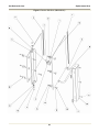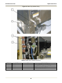
1
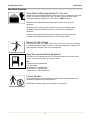
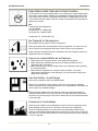
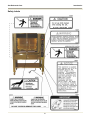
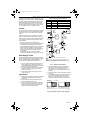
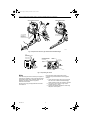
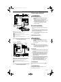
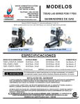
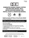
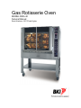
Gas Rotisserie Oven
MODEL DRG-40
Service Manual
Serial Numbers 120170 and Higher
Warranty Information
LIMITED ONE YEAR WARRANTY
BKI (The "Company") warrants to the original purchaser that at time of shipment from the
Company factory, this equipment will be free from defect in materials and workmanship. Written
notice of a claim under this warranty must be received by the Company within ONE YEAR from
the date of installation, but no longer than ONE YEAR AND THREE MONTHS from date of
shipment from the factory. Defective conditions caused by abnormal use or misuse, lack of or
improper maintenance, damage by third parties, alterations by unauthorized personnel, acts of
God, failure to follow installation and/or operating instructions, or any other events beyond the
reasonable control of the Company will NOT be covered under this warranty. The obligation of
the Company under this warranty shall be limited to repairing or replacing (at the option of the
Company) any part, with the exception of lamps, fuses, and glass (which are not covered under
warranty), which is found defective in the reasonable opinion of the Company. Any part found
defective by the Company will be repaired or replaced without charge F.O.B. factory,
Simpsonville, South Carolina or F.O.B. authorized BKI Distributor. The Company and/or its
authorized representatives will assume the normal replacement labor expense for the defective
part for the period of the warranty as stated above, excluding travel and/or other expenses
incidental to the replacement of the defective part, where replacement work is performed during
standard business hours and not subject to overtime, holiday rates, and/or any additional fees. IN
NO EVENT SHALL THE COMPANY BE LIABLE FOR LOSS OF USE, LOSS OF REVENUE OR
LOSS OF PRODUCT OR PROFIT OR FOR INDIRECT OR CONSEQUENTIAL DAMAGES
INCLUDING BUT NOT LIMITED TO, FOOD SPOILAGE OR PRODUCT LOSS. WARRANTY
DOES NOT COVER GLASS BREAKAGE. THE ABOVE WARRANTY IS EXCLUSIVE AND ALL
OTHER WARRANTIES, EXPRESS OR IMPLIED, ARE EXCLUDED INCLUDING THE IMPLIED
WARRANTIES OF MERCHANTABILITY AND FITNESS FOR A PARTICULAR PURPOSE.
REPLACEMENT PARTS
Any appliance replacement part, with the exception of lamps, fuses, and glass, which proves to
be defective in material or workmanship within ninety (90) days of installation will be replaced
without charge F.O.B. Factory, Simpsonville, SC or F.O.B. authorized BKI Distributor. The user
shall have the responsibility and expense of removing and returning the defective part to the
Company as well as the cost of reinstalling the replacement or repaired part.
The purchaser must post, in a prominent location, instructions to be
followed in the event the user smells gas. This information shall be
obtained by consulting the local gas supplier.
FOR YOUR SAFETY
Do not store or use gasoline or other flammable vapors or liquids
in the vicinity of this or any other appliance.
Improper installation, adjustment, alteration, service or
maintenance can cause property damage, injury or death. Read
the installation, operation and maintenance instructions
thoroughly before installing or servicing this equipment.
Gas Rotisserie Oven
Table of Contents
Table of Contents
Table of Contents .................................................................................................................................................... 1
Introduction.............................................................................................................................................................. 2
Safety Precautions ................................................................................................................................................ 2
Safety Signs and Messages ............................................................................................................................. 2
Safe Work Practices ......................................................................................................................................... 3
Safety Labels .................................................................................................................................................... 6
Installation................................................................................................................................................................ 8
Inspection for Shipping Damage ........................................................................................................................... 8
Preparation............................................................................................................................................................ 8
Location and Clearance ........................................................................................................................................ 9
Installation Procedure............................................................................................................................................ 9
Gas Conversion Instructions ............................................................................................................................... 10
Replacement Parts ................................................................................................................................................ 11
Assemblies .......................................................................................................................................................... 11
Accessories & Components ................................................................................................................................ 25
Wiring Diagrams .................................................................................................................................................... 27
Appendix A............................................................................................................................................................. 31
Notes....................................................................................................................................................................... 32
1
Gas Rotisserie Oven
Introduction
Introduction
Your DRG-40 is a computer controlled gas fired rotisserie oven. It utilizes a double revolving rotor system to
ensure even product cooking. The unit contains a single stage cook and hold computer with 5 customizable cook
programs. Electrical controls are provided for powering the unit, turning on inside lights, igniting upper/lower
burners, turning the rotors, filling the water bath and resetting the unit. A manual lever is supplied for draining
water from the water bath. The rotor system is removable to allow for easy maintenance and cleaning.
The BKI name and trademark on this unit assures you of the finest in design and engineering -- that it has been
built with care and dedication -- using the best materials available. Attention to the operating instructions
regarding proper installation, operation, and maintenance will result in long lasting dependability to ensure the
highest profitable return on your investment.
PLEASE READ THIS ENTIRE MANUAL BEFORE OPERATING THE UNIT. If you have
any questions, please contact your BKI Distributor. If they are unable to answer your
questions, contact the BKI Technical Service Department, toll free: 1-800-927-6887.
Outside the U.S., call 1-864-963-3471.
Safety Precautions
Always follow recommended safety precautions listed in this manual. Below is the safety alert symbol. When you
see this symbol on your equipment, be alert to the potential for personal injury or property damage.
Safety Signs and Messages
The following Safety signs and messages are placed in this manual to provide instructions and identify specific
areas where potential hazards exist and special precautions should be taken. Know and understand the meaning
of these instructions, signs, and messages. Damage to the equipment, death or serious injury to you or other
persons may result if these messages are not followed.
This message indicates an imminently hazardous situation which, if not avoided, will
result in death or serious injury.
This message indicates a potentially hazardous situation, which, if not avoided, could
result in death or serious injury.
This message indicates a potentially hazardous situation, which, if not avoided, may
result in minor or moderate injury. It may also be used to alert against unsafe practices.
This message is used when special information, instructions or identification are required
relating to procedures, equipment, tools, capacities and other special data.
2
Gas Rotisserie Oven
Introduction
Safe Work Practices
Wear Safe Clothing Appropriate To Your Job
Always wear your insulated mitts when handling hot racks or touching any hot metal
surface. If you lose or damage your mitts, you can buy new ones at your local
restaurant equipment supply store or from your local BKI Distributor.
Always wear non-skid shoes when working around the oven or any other
equipment.
Never wear loose clothing such as neckties or scarves while operating this
equipment. Keep loose hair tied back or in a hair net while operating this
equipment.
Always wear appropriate personal protection equipment during the cleaning
process to guard against possible injury from hot cleaning solution.
Beware of High Voltage
This equipment uses high voltage. Serious injury can occur if you or any untrained
or unauthorized person installs, services, or repairs this equipment. Always Use an
Authorized Service agent to Service Your Equipment.
Keep this manual with the Equipment
This manual is an important part of your equipment. Always keep it near for easy
access. If you need to replace this manual, contact:
BKI
Technical Services Department
P.O. Box 80400
Simpsonville, S.C. 29680-0400
Or call toll free: 1-800-927-6887
Outside the U.S., call 864-963-3471
Protect Children
Keep children away from this equipment. Children may not understand that this
equipment is dangerous for them and others.
NEVER allow children to play near or operate your equipment.
3
Gas Rotisserie Oven
Introduction
Keep Safety Labels Clean and in Good Condition
Do not remove or cover any safety labels on your equipment. Keep all safety labels
clean and in good condition. Replace any damaged or missing safety labels. Refer
to the Safety Labels section for illustration and location of safety labels on this unit.
If you need a new safety label, obtain the number of the specific label illustrated on
page 6, then contact:
BKI
Technical Services Department
P.O. Box 80400
Simpsonville, S.C. 29680-0400
Or call toll free: 1-800-927-6887
Outside the U.S., call 864-963-3471
Be Prepared for Emergencies
Be prepared for fires, injuries, or other emergencies.
Keep a first aid kit and a fire extinguisher near the equipment. You must use a 40pound Type BC fire extinguisher and keep it within 25 feet of your equipment.
Keep emergency numbers for doctors, ambulance services, hospitals, and the fire
department near your telephone.
Know your responsibilities as an Employer
• Make certain your employees know how to operate the equipment.
• Make certain your employees are aware of the safety precautions on the
equipment and in this manual.
• Make certain that you have thoroughly trained your employees about operating
the equipment safely.
• Make certain the equipment is in proper working condition. If you make
unauthorized modifications to the equipment, you will reduce the function and
safety of the equipment.
Use Gas Safely-- Avoid Danger
Gas can be a dangerous fuel if not handled safely.
Make sure to ventilate the oven properly. If the oven is not properly ventilated,
carbon monoxide can be released around the oven. Asphyxiation or suffocation can
occur if gas is not ventilated properly.
Before using this appliance for the first time, contact your local gas supplier for
instructions about what to do if you smell gas. Post those instructions somewhere
near the oven, so that everyone who uses or works near the oven knows what to do
if they smell gas.
Clearance to Combustibles
Observe proper clearance to combustibles as noted on the oven rating tag. Never
place anything on top of the oven. The flues on top of the oven should be a
minimum horizontal distance of 6 inches from any combustible material. Never
place any combustible materials above the top of the oven. Never use any solvents
near the oven. The open flame inside the oven could ignite solvent fumes, resulting
in a fire or explosion.
4
Gas Rotisserie Oven
Introduction
Do Not Smoke Near The Oven
This oven uses combustible fuels to operate. Smoking near this oven could possibly
cause a fire. Do not allow anyone to smoke near this oven.
5
Gas Rotisserie Oven
Introduction
Safety Labels
6
Gas Rotisserie Oven
Introduction
7
Gas Rotisserie Oven
Installation
Installation
Inspection for Shipping Damage
It is the owners’ responsibility to file all freight claims with the delivering truck line. Inspect all cartons and crates
for damage as soon as they arrive. If damage to cartons or crates is found, or if a shortage is found, note this on
the bill of lading (all copies) prior to signing.
If damage is found when the equipment is opened, immediately call the delivering truck line and follow up the call
with a written report indicating concealed damage to your shipment. Ask for an immediate inspection of your
concealed damage item. Packaging material MUST be retained to show the inspector from the truck line.
Preparation
There are several things the installer must know before installing the oven. These are listed below:
When using natural gas, the supply pressure must never drop below 7 inches of water
column. If the supply pressure can exceed 14 inches of water column, a pressure
regulator must be used. This regulator must be sized to ensure that the pressure never
goes below 7 inches of water column while the unit is in operation.
•
The oven installation must conform with city or county standards for gas appliances and gas piping. If
your area does not have local codes, consult the National Fuel Gas Code, ANSI Z223.1/NFPA 54, or the
Natural Gas and Propane Installation Code, CSA B149.1. In Europe, city and country codes are enforced.
Do not attempt to test the gas pressure of your oven. Pressure testing should be done
only by an authorized Service Agent.
•
During any pressure testing of the gas supply system, the oven must be protected. The oven and its
individual shutoff valve must be disconnected from the gas supply piping system during any pressure
testing of that system at test pressures in excess of ½ psi (3.5 kPa). The oven must be isolated from the
gas supply piping system by closing its individual manual shutoff valve during any pressure testing of the
gas supply piping system at test pressures equal to or less than ½ psi (3.5 kPa).
•
The oven must be electrically grounded to conform with the local code of your city or county. If your area
does not have local codes, consult the latest version of the National Electrical Code ANSI/NFPA 70, or
the Canadian Electrical Code, CSA C22.2. In EUROPE, city and country codes are enforced.
•
A schematic diagram of the unit is located inside the control cabinet.
•
The Authorized Service Agent that installs your oven must connect the cord set at the rear of the oven to
an electrical source with a voltage matching that stamped on the name and rating tag. Refer to the wiring
diagrams in this manual.
•
Make sure a connector is used that complies with the Standard for Connectors for Movable Gas
Appliances, ANSI Z21.69 • CSA 6.16.
•
Make sure a quick-disconnect device is used that complies with the Standard for Quick-Disconnect
Devices for Use With Gas Fuel, ANSI Z21.41 • CSA 6.9.
•
In Europe, the installer must supply the gas supply connector.
8
Gas Rotisserie Oven
Installation
•
Make sure a restraining device is used that complies with the Standard for Commercial Gas Ranges,
ANSI Z83.11/CGA 1.8 (such as BKI part number FT0279) to guard against transmission of strain to the
connector.
•
The drain on the DRG-40 is a ¾” ball valve. Under NO circumstances, should this valve be hard plumbed
to a drain line. A short nipple may be used to direct the discharge into a 2” drain that should have a bell
reducer (to act as a funnel) placed on the end of drain line. The best configuration is to place this bell
reducer just below the valve. Using a ¾” line to come out from under the oven is not recommended, as it
would be easy to plug up.
•
Retain the manual for future reference.
Location and Clearance
Install your oven in a well-ventilated area. This will ensure that the gas burns properly and will help prevent any
fires. When deciding on a location, remember the following:
•
All gas-burning appliances need enough fresh air for combustion.
•
Locate the oven where it can be vented into an adequate exhaust hood. Your local gas utility must
approve your ventilation system. Consult a ventilation or heating company to help you design an
adequate system that meets ventilation codes and standards for your city or county. In Europe, install
according to local codes.
•
Keep the oven away from any combustibles such as curtains, wood paneling, boxes, or towels. The flue
riser at the top of the oven should also be kept away from any flammable material.
•
Observe proper clearance to combustibles as noted on the oven rating tag. Never place anything on top
of the oven. The flues on top of the oven should be a minimum horizontal distance of 6 inches from any
combustible material. Never place any combustible materials above the top of the oven. Never use any
solvents near the oven. The open flame inside the oven could ignite solvent fumes, resulting in a fire or
explosion.
•
Keep the work area around the oven free of objects that might block fresh air or that might cause a fire.
•
Do not attach an extension to the exhaust stack. This may stop the burner from operating properly, cause
the burner to go off, or, cause other dangerous malfunctions. It may also cause a strong draft in the room.
A draft can interfere with the burner.
•
Do not locate the oven near strong drafts. Keep the oven away from doors that are opened and closed
frequently.
Installation Procedure
Ensure that an authorized BKI service agent installs the oven. An authorized BKI service
agent should be a qualified gas service technician and a licensed electrician.
Failure to restrain the oven could allow it to move, causing a possible break in the gas
line resulting in an explosive condition.
1. Install an ANSI Z83.11/CGA 1.8 compliant restraining device (such as BKI part number FT0279) per the
instructions below:
a. Mount the wall attachment according the restraining device manufacturer instructions.
b. If possible, loop one end of the restraining cable around one of the rear legs and attach the
spring-loaded hook to the cable then attach the other spring-loaded hook to the wall attachment.
9
Gas Rotisserie Oven
Installation
If you are unable to do this, drill a small ¼” hole through the back flange of the shelf, then follow
the restraining device manufacturer instructions to finish the installation.
Use appliance connectors and quick-disconnect devices that are in compliance with the
applicable ANSI and CSA standards.
2. Attach an appliance connector to the oven according to the instructions provided by the appliance
connector manufacturer.
3. Connect the gas supply to the oven. In Europe, the gas supplier must provide the gas hookup connecting
line.
4. Lock the casters so the oven does not move. Every time you use the oven, make sure the casters are
locked so the oven cannot move. (In Canada: refer to caster codes CAN 1-6.10 M88 and CAN 1-6.9
M79.)
5. Turn on the gas at the gas supply valve.
6. Check for gas leaks from the gas supply to the oven gas valve using a soap and water solution. If a leak
is detected, tighten the connection where the leak occurs.
7. Connect the three-prong (grounded) plug directly into a properly grounded three-prong receptacle.
8. Apply power to the oven.
9. Perform the following procedures provided in the Startup and Checkout section of the VR8105, VR8205,
and VR8305 Direct Ignition Combination Gas Controls Installation Instructions (69-1226-2). Refer to
Appendix A.
•
•
•
•
Perform Gas Leak Test
Turn On System
Turn On Main Burner
Check and Adjust Gas Input Burner Ignition (for Standard model Pressure Regulator)
10. Place the HEAT switch, LOWER FLAME switch, and LIGHTS switch in the “OFF” position.
11. Wait at least five minutes to allow oven to cool.
12. Place the POWER switch and ROTOR switch in the “OFF” position.
Gas Conversion Instructions
To convert the gas system from a Natural Gas to LP Gas application or vice versa, contact the BKI Technical
Service Department, toll free: 1-800-927-6887. Outside the U.S., call 1-864-963-3471.
10
Gas Rotisserie Oven
Replacement Parts
Replacement Parts
Use the information in this section to identify replacement parts. To order replacement parts, call your local BKI
sales and service representative. Before calling, please note the serial number on the rating tag affixed to the unit.
Assemblies
Description
Assembly #
Figure #
Table #
CONTROL PANEL
AN44022900
Figure 1
Table 1
THERMOCOUPLE
AA44012400
Figure 2
Table 2
UPPER GAS PIPING
AB44001100
Figure 3
Table 3
DUAL PASSIVE ROTOR
AB44106400
Figure 4
Table 4
SINGLE/DUAL DRIVE ROTOR
AB44106500
Figure 5
Table 5
SINGLE PASSIVE ROTOR
AB44015500
Figure 6
Table 6
JACKSHAFT
AB44107500
Figure 7
Table 7
DRIVE SIDE DOOR
AB44107800
Figure 8
Table 8
PASSIVE SIDE DOOR
AB44108300
Figure 9
Table 9
WATER PIPE
AN44013500
Figure 10
Table 10
11
Gas Rotisserie Oven
Replacement Parts
Figure 1. Control Panel (AN44022900)
12
Gas Rotisserie Oven
Replacement Parts
Table 1. Control Panel (AN44022900) Parts
ITEM #
1
2
3
4
5
6
7
8
9
10
11
12
13
14
15
PART #
AB44007200
CB0058
CP0022
CS0005
F0097
FH0001
S0304
S0307
S0308
S0309
S0339
S0340
TF0005
TF0045
AB44023800
QTY
1
1
1
1
2
2
5
6
1
1
2
1
2
1
1
DESCRIPTION
TERM BLOCK ASSY DRG
BREAKER, CIRCUIT 1 AMP 250V
CONTROLLER, DIGT TEMP/TIME
CORD SET, 115V 7'6"
FUSE, 15A 300V SC15 TIME DELAY
FUSE HOLDER, 15A 300V HPF-EE
SWITCH, 2 POS OPERATOR BLK
SWITCH, NO BLOCK GE P9B10VN
SWITCH, NO/NC BLOCK GE 9PB11VN
SWITCH, MUSHROOM PUSH BLACK
SWITCH, CONTACT BLOCK 2 NO
SWITCH, PUSH BUTTON BLUE RECESSED
TRANSFORMER, 120-24V LGF
TRANSFORMER, 230/115 PRI 175VA
TERM BLOCK ASSY NEUTRAL LINES DRG40
13
Gas Rotisserie Oven
Replacement Parts
Figure 2. Thermocouple (AA44012400)
Table 2. Thermocouple (AA44012400) Parts
ITEM #
PART #
F0173
T0020
T0085
TU0012
QTY
1
0.25
1
0.25
DESCRIPTION
FERRITE BEAD
TUBING, HEAT SHRINK 1/4 PLASTIC
THERMOCOUPLE, TYPE K T-2016
TUBING, RED SILICONE SRT-110
14
Gas Rotisserie Oven
Replacement Parts
Figure 3. Upper Gas Piping (AB44001100)
Table 3. Upper Gas Piping (AB44001100) Parts
ITEM #
1
2
3
4
5
6
7
8
PART #
C0739
FB44007109
FT0521
FT0522
FT0523
SCR280
T0008*
AN44116100*
QTY
1
2
2
1
1
4
1
3
9
MB44115400*
2
DESCRIPTION
VALVE, GAS VR8205A2123
GAS VALVE MOUNT DRG
REDUCER, TUBE END 1/2-3/8
TEE, MALE BRANCH 1/2-1/2-1/2
CONNECTOR, MALE 1/2 NPT-1/2 COMPRESS
SCREW, 8-32 X 3/8 PHIL TRUSS
THERMOSTAT, HI LIMIT 572¦F
SURGE SUPPRESSOR (ONE USED ON
EACH IGNITION MODULE)
IGNITION/SENSE PROBE
* - These components are not part of the Upper Gas Piping Assembly (AB44001100) but are shown here for reference only.
15
Gas Rotisserie Oven
Replacement Parts
Figure 4. Dual Passive Rotor (AB44106400)
Table 4. Dual Passive Rotor (AB44106400) Parts
ITEM #
1
2
3
4
5
6
7
8
9
10
11
12
13
14
PART #
WSH093
SCR383
WSH260
SCR384
B0241
H0106
H0067
NUT131
G0103
FT0366
RO0027
FT0367
WSH256
WSH257
QTY
24
24
2
2
8
1
8
24
8
8
1
8
8
8
DESCRIPTION
WASHER, #10 LOCK
SCREW, 10-24 X 1/2" PHIL TRUSS HD
WASHER, 5/16 S/S LOCKWASHER
SCREW, 5/16-18 X 1/2 S/S HEX
BEARING, .75 ID X 1. OD .813 L
HUB, PASSIVE DUAL DRG
HUB, PLANETARY GEAR 951
NUT, 10-24 SS 18-8 HEX
GEAR, PLANETARY(5) 6 DIA PITCH
RETAINING RING, PLANETARY GEAR
ROTOR, 23" DIA. ACTIVE DRG40
SHIM, PLANETARY GEAR DR34
WASHER, THRUST .765ID X 1.25OD
WASHER, THRUST .765ID X 1.25OD
16
Gas Rotisserie Oven
Replacement Parts
Figure 5. Single/Dual Drive Rotor (AB44106500)
Table 5. Single/Dual Drive Rotor (AB44106500) Parts
ITEM #
1
2
3
4
5
6
7
8
9
10
11
12
13
14
15
PART #
WSH093
SCR383
WSH260
SCR399
B0241
MC0054
H0104
H0067
NUT131
G0103
FT0366
RO0027
FT0367
WSH256
WSH257
QTY
24
24
2
2
8
1
1
8
24
8
8
1
8
8
8
DESCRIPTION
WASHER, #10 LOCK
SCREW, 10-24 X 1/2" PHIL TRUSS HD
WASHER, 5/16 S/S LOCKWASHER
SCREW, 5/16-18 X 3/4 HEX HD
BEARING, .75 ID X 1. OD .813 L
DRIVE COUPLING, MALE DRG40
HUB, DRIVE SIDE DRG
HUB, PLANETARY GEAR 951
NUT, 10-24 SS 18-8 HEX
GEAR, PLANETARY(5) 6 DIA PITCH
RETAINING RING, PLANETARY GEAR
ROTOR, 23" DIA. ACTIVE DRG40
SHIM, PLANETARY GEAR DR34
WASHER, THRUST .765ID X 1.25OD
WASHER, THRUST .765ID X 1.25OD
17
Gas Rotisserie Oven
Replacement Parts
Figure 6. Single Passive Rotor (AB44015500)
Table 6. Single Passive Rotor (AB44015500) Parts
ITEM #
1
2
3
4
PART #
RO0028
SCR384
WSH260
H0105
QTY
1
2
2
1
DESCRIPTION
ROTOR, 23" DIA. PASSIVE DRG40
SCREW, 5/16-18 X 1/2 HEX CAP
WASHER, 5/16 S/S LOCKWASHER
HUB, PASSIVE SINGLE
18
Gas Rotisserie Oven
Replacement Parts
Figure 7. Jackshaft (AB44107500)
Table 7. Jackshaft (AB44107500) Parts
ITEM #
1
2
3
4
5
PART #
B0239
FT0424
PN44113800
SH0104
WSH253
QTY
2
2
1
1
2
DESCRIPTION
BEARING, FCJ16F20-8
CLAMP COLLAR C12L14 1X1.75X.5
JACKSHAFT MOUNT PAINTED DRG-40
SHAFT, ROTOR MOTOR DRIVE
WASHER, THRUST 1.025X2 PER PRINT
19
Gas Rotisserie Oven
Replacement Parts
Figure 8. Drive Side Door (AB44107800)
20
Gas Rotisserie Oven
Replacement Parts
Table 8. Drive Side Door (AB44107800) Parts
ITEM #
1
2
3
4
5
6
7
8
9
10
11
12
13
14
15
16
17
18
19
20
21
22
23
PART #
WSH266
SCR060
BLT252
F0136
BLT250
FB44108803
MA44109000
MA44109100
GL0272
GL0271M
FB44108002
WSH044
WSH260
NUT132
NUT054
H0131
SCR383
SP0022
SP0041
FA44108900
F0086
WSH258
WB44107900
QTY
2
2
5
6
3
1
1
1
1
1
1
2
6
1
6
1
1
1
6
12
2
6
1
DESCRIPTION
WASHER, 1/4" FLAT S/S
SCREW, 1/4-20 X 1 HEX CAP
BOLT, 5/16-1 SLTD TRUSS
THREAD INSERT 10-24 STEEL HEX
BOLT, 5/16-18 X 3/4 S/S CARRIAGE
DOOR GLASS LOCK DRG-40
GLASS TRIM, OUTER DOOR DRG-40
GLASS TRIM, INNER DOOR DRG-40
GLASS, 25 X 21.625 TEMP
GLASS, MATRIX RH 32 X 20.188
INNER DOOR SUPPORT DR.SIDE DRG40
WASHER, 1/4 LOCK ZINC PLTD
WASHER, 5/16 S/S LOCKWASHER
NUT, 10-24 SS 18-8 HEX CAP
NUT, 5/16-18 HEX
HANDLE, TUBULAR S/S P47-1012
SCREW, 10-24 X 1/2" PHIL TRUSS HD
SPACER, DELRIN .375 ID X 1" OD
SPACER, TEFLON-DOOR GLASS
WASHER, TEFLON DRG-40
THREAD INSERT 5/16-18 STEEL
WASHER, FENDER 5/16 X 1 1/2
DOOR SUPPORT WELD. DRG-40
21
Gas Rotisserie Oven
Replacement Parts
Figure 9. Passive Side Door (AB44108300)
22
Gas Rotisserie Oven
Replacement Parts
Table 9. Passive Side Door (AB44108300) Parts
ITEM #
1
2
3
4
5
6
7
8
9
10
11
12
13
14
15
16
17
18
19
20
21
22
23
PART #
WSH266
SCR060
BLT252
F0136
BLT250
FB44108803
MA44109000
MA44109100
GL0272
GL0270M
FB44108502
WSH044
WSH260
NUT132
NUT054
H0131
SCR383
SP0022
SP0041
FA44108900
F0086
WSH258
WB44107900
QTY
2
2
5
6
3
1
1
1
1
1
1
2
6
1
6
1
1
1
6
12
2
6
1
DESCRIPTION
WASHER, 1/4" FLAT S/S
SCREW, 1/4-20 X 1 HEX CAP
BOLT, 5/16-1 SLTD TRUSS
THREAD INSERT 10-24 STEEL HEX
BOLT, 5/16-18 X 3/4 S/S CARRIAGE
DOOR GLASS LOCK DRG-40
GLASS TRIM, OUTER DOOR DRG-40
GLASS TRIM, INNER DOOR DRG-40
GLASS, 25 X 21.625 TEMP
GLASS, MATRIX LH 32 X 20.188
INNER DR.SUPPORT PASS.SIDE DRG40
WASHER, 1/4 LOCK ZINC PLTD
WASHER, 5/16 S/S LOCKWASHER
NUT, 10-24 SS 18-8 HEX CAP
NUT, 5/16-18 HEX
HANDLE, TUBULAR S/S P47-1012
SCREW, 10-24 X 1/2" PHIL TRUSS HD
SPACER, DELRIN .375 ID X 1" OD
SPACER, TEFLON-DOOR GLASS
WASHER, TEFLON DRG-40
THREAD INSERT 5/16-18 STEEL
WASHER, FENDER 5/16 X 1 1/2
DOOR SUPPORT WELD. DRG-40
23
Gas Rotisserie Oven
Replacement Parts
Figure 10. Water Pipe (AN44013500)
Table 10. Water Pipe (AN44013500) Parts
ITEM #
1
2
3
4
PART #
FT0272
FT0470
SCR138
SV0010
QTY
2
1
2
1
DESCRIPTION
ELBOW, STREET, 90° ½” NPT, SS
CONNECTOR, HOSE 3/4" X 1/2"NPT
SCREW, 10 X 1/2 PHIL TR HD
VALVE, SOLENOID 120/60
24
Gas Rotisserie Oven
Replacement Parts
Accessories & Components
Description
Accessories
BASKET, MEAT LARGE CLAMSHELL (FOR DUAL SHAFT)
BASKET, MEAT LARGE CLAMSHELL (FOR SINGLE SHAFT)
BASKET, MEAT SM CLAMSHELL (FOR DUAL SHAFT)
BASKET, MEAT SM CLAMSHELL (FOR SINGLE SHAFT)
VEE SPIT 2 BIRD DRG (FOR DUAL SHAFT)
VEE SPIT 3 BIRD DRG (FOR DUAL SHAFT)
VEE SPIT 6 BIRD DRG (FOR SINGLE SHAFT)
INSULATED MITT 13"
HOSE, 60" GAS CONNECTOR W/ RESTRAINT (FT0279)
RESTRAINT (ONLY)
PERMATEX INDUST. SUPERLUBE
Components
LOG, SPLIT BRANCH 9-1/2" (3)
CASTER 5"1/2-13 X 3/4 STUD LOCK
VALVE, GAS VR8205A2123
DIRECT SPARK IGNITION
IGN.PROBE, LOWER BURNER DRG-40
IGN.PROBE, UPPER BURNER DRG-40
MOTOR, 110-120/220-240 .94/.55 AMP
CHAIN, #40 ROLLER 106 PITCHES
LAMPHOLDER W/BULB 12V 20W (OSRAM)
DUAL REMOVABLE SHAFT
ROTOR, CENTER DRG (For Dual Rotor Configuration)
SHAFT ASSY, SGL REMOV DRG
Part #
Figure #
Item #
MB0015
MB0021
MB0011
MB0020
MF0031
MF0021
MF0028
G0052
H0136
FT0279
L0200
Figure 11
1
Figure 11
2
Figure 11
3
Figure 11
Figure 11
Figure 11
Figure 11
4
5
6
7
L0500
C0425
C0739
C0740
MB44115500
MB44115400
M0087
CH0014
LH0024
AB44106600
RO0031
AB44015000
Figure 11
Figure 11
Figure 11
Figure 11
Figure 11
Figure 11
Figure 11
Figure 11
Figure 11
Figure 11
Figure 11
Figure 11
8
9
10
11
12
13
14
15
16
17
18
19
Figure 11. Accessories & Components
1
2
3
4
5
6
25
Gas Rotisserie Oven
Replacement Parts
7
8
9
10
11
12
13
14
15
16
17
18
19
26
Gas Rotisserie Oven
Wiring Diagrams
Wiring Diagrams
27
Gas Rotisserie Oven
Wiring Diagrams
28
Gas Rotisserie Oven
Wiring Diagrams
29
Gas Rotisserie Oven
Wiring Diagrams
30
Gas Rotisserie Oven
Appendix A
Appendix A
Gas Control Valve Instructions
31
69-1226-2.fm Page 1 Thursday, November 13, 2003 12:50 PM
VR8105, VR8205, and VR8305
Direct Ignition Combination
Gas Controls
INSTALLATION INSTRUCTIONS
APPLICATION
These direct ignition gas controls are used in gas-fired
appliances with up to 415 ft3/hr. capacity at 1 in. wc
pressure drop (8.5 m3/hr at 0.25 kPa) on natural gas.
They include a manual valve, two automatic operators
and a pressure regulator.
These gas controls are available in a range of valve
capacities, see Table 1. (Table 2 provides gas capacity
conversion factors.) The suffix letter indicates
temperature range and regulator type, see Table 3.
Table 1. Valve Capacitya
Model
VR8105
Size InletOutlet (in.)
1/2 x 1/2
AGA Certified
AGA Certified Minimum
Capacity for Natural
Regulation for
Gas
Natural Gas
ft3/hr
m3/hr
ft3/hr
AGA Certified Maximum
Regulation for
Natural Gas
m3/hr
ft3/hr
m3/hr
85
2.3
d
10
0.4
120
3.4
VR8205
150
4.2
20e
0.6
200
5.7
VR8305b,c
240
6.8
f
0.8
340
9.6
30
VR8305b,c
1/2 x 3/4
270
7.6
370
10.5
VR8305b,c
3/4 x 3/4
300
8.5
415
11.8
Capacity based on 1000 Btu/ft3, 0.64 sp gr natural gas at 1 in. wc pressure drop (37.3 MJ/m3, 0.64 sp gr natural gas
at 0.25 kPa pressure drop).
b Capacity is reduced by 5 percent when using an outlet screen.
c Valves are guaranteed at only 77 percent of the rating.
d Minimum regulation for LP gas is 15,000 Btuh.
e Minimum regulation for LP gas is 40,000 Btuh.
f Minimum regulation for LP gas is 50,000 Btuh.
a
Table 2. Gas Capacity Conversion Factor.
Gas
Specific
Gravity
Multiply Listed
Capacity By
Table 3. Model Number Suffix Letter Designation.
Model No.
Suffix
Letter
Manufactured 0.60
0.516
Mixed
0.70
0.765
A
Propane
1.53
1.62
C
H
K
M
® U.S. Registered Trademark
Copyright © 1999 Honeywell Inc. • All Rights Reserved
Ambient
Temperature
Range
Pressure Regulator
Type
0°F to 175°F
Standard
(-18°C to +79°C) Step-opening
Slow Opening
-40°F to +175°F
(-40°C to +79°C) Standard
P
Step-opening
Q
Two-stage
R
Convertible
69-1226-2
69-1226-2.fm Page 2 Thursday, November 13, 2003 12:50 PM
VR8105, VR8205, AND VR8305 DIRECT IGNITION COMBINATION GAS CONTROLS
SPECIFICATIONS
PLANNING THE INSTALLATION
Body Pattern: Straight through; see Table 1 for inlet and
outlet size.
WARNING
Fire or Explosion Hazard.
Can cause property damage, severe injury,
or death.
Follow these warnings exactly:
1. Plan the installation as outlined below.
2. Plan for frequent maintenance as described in
the Maintenance section.
Heavy demands are made on the controls when direct
ignition systems are used on central heating equipment
in barns, greenhouses, and commercial properties and
on heating appliances such as commercial cookers,
agricultural equipment, industrial heating equipment and
pool heaters.
Electrical Ratings:
Voltage and Frequency: 24 Vac, 60 Hz.
Current Draw: 0.5A with both operators energized.
Capacity: See Table 1.
Conversion:
Use conversion factors in Table 2 to convert capacities
for other gases.
Regulation Range: See Table 1.
Natural-LP Gas Conversion Kits: See Table 4.
Special steps may be required to prevent nuisance
shutdowns and control failure due to frequent cycling,
severe environmental conditions related to moisture,
corrosive chemicals, dust or excessive heat. These
applications require Honeywell Home and Building
Control Engineering review; contact your Honeywell
Sales Representative for assistance.
Pipe Adapters:
Angle and straight adapters available for 3/8-, 1/2- and
3/4-in. pipe. See Table 5. Flange kits include one
flange with attached O-ring, four mounting screws, a
9/64 in. hex wrench and instructions.
Approvals:
American Gas Association Design Certificate: L2025006.
Canadian Gas Association Design Certificate: L2025006.
Australian Gas Association Design Certificate: 4214.
Approved for Delta C applications.
European Community (CE) Certificate: Pending.
Review the following conditions that can apply to your
specific installation and follow the precautions
suggested.
Frequent Cycling
This control is designed for use on appliances that
typically cycle three to four times an hour only during the
heating season. In year-around applications with greater
cycling rates, the control can wear out more quickly.
Perform a monthly checkout.
Table 4. Natural-LP Gas Conversion Kits
Model No. Suffix Letter
Kit to Convert Natural Gas to LP
Kit to Convert LP to Natural Gas
H, K, M
393691
394588
P
Not field convertible.
Not field convertible.
Q
396021
396025
R
Not required, convertible valve.
Not required, convertible valve.
Table 5. Flange Adapter Part Numbers.
Part No.a,b
Inlet/Outlet
Pipe Size (in. NPT)
3/8
Without Hex Wrench
Flange Type
With Hex Wrench
Straight
393690-1
393690-11
3/8
Elbow
393690-2
393690-12
1/2
Straight
393690-6
393690-16
1/2
Elbow
393690-3
393690-13
3/4
Straight
393690-4
393690-14
3/4
Elbow
393690-5
393690-15
a
b
Flange kits include one flange, one O-ring and four mounting screws.
Do not use flanges on control models with 3/4 in. inlet and 3/4 in. outlet. On models with 1/2 in. inlet and 3/4 in. outlet,
use flanges only on the 1/2 in. inlet side.
69-1226—2
2
69-1226-2.fm Page 3 Thursday, November 13, 2003 12:50 PM
VR8105, VR8205, AND VR8305 DIRECT IGNITION COMBINATION GAS CONTROLS
Table 6 shows additional specifications for the CE-only
models.
Table 6. VR8205A,H/VR8305A,H CE Models.
Specification
Main Valve Connection
VR8205A,H (CE Model Only)
1/2 in. ISO, 7/1 internal thread
(BSP.PL).
VR8305A,H (CE Model Only)
1/2 in., 3/4 in. ISO, 7/1 internal thread
(BSP.PL).
Ambient Temperature Range
-20°C to +70°C (-4°F to +158°F)
Maximum Inlet Pressure
60 mbar (24 in. wc).
Pressure Regulation
Servo regulator with adjustable outlet pressure; in accordance with EN 88
Class C.
Natural gas: 9 mbar, typical; LP: 20 mbar, typical.
Regulator Adjustment
For natural gas, 7.5 mbar to 12.5 mbar field adjustable.
For LP gas, 20 mbar to 30 mbar field adjustable.
Ground Terminal
6.3 mm
Pressure Taps
9 mm OD
Valve Classification
B+D
C+D
appliance operates at very high temperatures, use
insulation, shielding, and air circulation, as necessary, to
protect the control. Proper insulation or shielding should
be provided by the appliance manufacturer; verify proper
air circulation is maintained when the appliance is
installed.
CAUTION
Equipment Damage Hazard.
Improper use can damage equipment.
Read the instructions before use. This control
must be installed in accordance with the rules in
force.
INSTALLATION
Water or Steam Cleaning
If a control gets wet, replace it. If the appliance is likely to
be cleaned with water or steam, protect (cover) the
control and wiring from water or steam flow. Mount the
control high enough above the bottom of the cabinet so it
does not get wet during normal cleaning procedures.
When Installing this Product…
1.
2.
High Humidity or Dripping Water
3.
Dripping water can cause the control to fail. Never install
an appliance where water can drip on the control. In
addition, high ambient humidity can cause the control to
corrode and fail. If the appliance is in a humid
atmosphere, make sure air circulation around the control
is adequate to prevent condensation. Also, regularly
check out the system.
4.
Read these instructions carefully. Failure to follow
them could damage the product or cause a
hazardous condition.
Check the ratings given in the instructions and on
the product to make sure the product is suitable for
your application.
Installer must be a trained, experienced service
technician.
After installation is complete, check out product
operation as provided in these instructions.
WARNING
Fire or Explosion Hazard.
Can cause property damage, severe injury or
death.
Follow these warnings exactly:
Corrosive Chemicals
Corrosive chemicals can attack the control, eventually
causing a failure. If chemicals are used for routine
cleaning, avoid contact with the control. Where
chemicals are suspended in air, as in some industrial or
agricultural applications, protect the control with an
enclosure.
1. Disconnect power supply before wiring to
prevent electrical shock or equipment damage.
2. To avoid dangerous accumulation of fuel gas,
turn off gas supply at the appliance service
valve before starting installation, and perform
Gas Leak Test after installation is complete.
3. Always install a sediment trap in gas supply
line to prevent contamination of gas control.
4. Do not force the gas control knob. Use only
your hand to turn the gas control knob. Never
use any tools. If the gas control knob does not
operate by hand, the gas control should be
replaced by a qualified service technician.
Force or attempted repair may result in fire or
explosion.
Dust or Grease Accumulation
Heavy accumulations of dust or grease can cause the
control to malfunction. Where dust or grease can be a
problem, provide covers for the control to limit
contamination.
Heat
Excessively high temperatures can damage the control.
Make sure the maximum ambient temperature at the
control does not exceed the rating of the control. If the
3
69-1226—2
69-1226-2.fm Page 4 Thursday, November 13, 2003 12:50 PM
VR8105, VR8205, AND VR8305 DIRECT IGNITION COMBINATION GAS CONTROLS
T
NA
T
NA
T
IMPORTANT
These gas controls are shipped with protective
seals over the inlet and outlet tappings. Do not
remove the seals until ready to install adapters
or connect the piping.
P
OTHER SIDE
OF CAP
PRESSURE
REGULATOR
CAP
Follow the appliance manufacturers instructions if
available; otherwise use these instructions as a guide.
L
OR
L
NA
T
NA
Equipment Damage.
Can burn out valve coil terminals.
Never apply a jumper across (or short) the valve
coil terminals, even temporarily.
P
CAUTION
M11678
Converting Gas Control from Natural Gas
to LP Gas (or LP Gas to Natural Gas)
Fig. 1. Top view of convertible pressure regulator
cap.
Install Adapters To Control
WARNING
If adapters are being installed on the control, mount them
as follows:
Fire Or Explosion Hazard.
Can cause property damage, severe injury
or death.
1. Do not attempt to convert step-opening models
(suffix letter P).
2. Always change the main and pilot burner
orifices when converting from natural to LP gas
or from LP to natural gas. Carefully follow
appliance manufacturer specifications and
instructions to assure proper appliance
conversion.
3. Gas controls are factory-set for natural (and
manufactured) or LP gas. Do not attempt to
use a gas control set for natural
(manufactured) gas on LP gas, or a gas control
set for LP gas on natural (manufactured) gas.
Controls with standard, slow-opening, and two-stage
regulators (model numbers with suffix H, K, M, or Q) can
be converted from one gas to the other with a conversion
kit (ordered separately). See Table 4 for the correct
conversion kit.
Flanges
1.
2.
3.
4.
Choose the appropriate flange for your application.
Remove the seal over the ignition system control
inlet or outlet.
Make sure that the O-ring is fitted in the groove of
the flange. If the O-ring is not attached or is
missing, do not use the flange.
With the O-ring facing the gas control, align the
screw holes on the control with the holes in the
flange. Insert and tighten the screws provided with
the flange. See Fig. 2. Tighten the screws to 25
inch-pounds of torque to provide a gas-tight seal.
Convertible Pressure Regulators
Controls with suffix letter R are convertible pressure
regulator models. They can be converted from natural
gas to LP gas or from LP gas to natural gas without a
conversion kit.
1
VALVE OUTLET
Before converting the control from one gas to another,
check the control label and the appliance manufacturer’s
rating plate to determine if the pressure regulator setting
(factory set) will meet the appliance manifold
requirements after conversion.
FLANGE
9/64 INCH HEX SCREWS (4)
1
NOTE: Convertible pressure regulator models (suffix
letter R) do not have field-adjustable regulators.
3.
Bushings
1.
2.
Remove the pressure regulator cap, Fig. 1.
Invert the cap so that the letters appear that
represent the gas type appropriate for the
appliance. NAT for natural manufactured gas, LP
for liquid petroleum gas.
Replace the cap and tighten firmly.
69-1226—2
M9046
Fig. 2. Firmly fasten flange to valve, but do not
overtighten screws.
If the factory pressure regulator setting meets the
appliance manifold requirement, convert the control as
follows:
1.
2.
DO NOT OVERTIGHTEN SCREWS. TIGHTEN TO
25 INCH-POUNDS.
3.
4
Remove the seal over the control inlet or outlet.
Apply a moderate amount of good quality pipe
compound to the bushing, leaving two end threads
bare. On an LP installation, use compound that is
resistant to LP gas. Do not use Teflon tape.
Insert the bushing in the control and carefully
thread the pipe into the bushing until tight.
69-1226-2.fm Page 5 Thursday, November 13, 2003 12:50 PM
VR8105, VR8205, AND VR8305 DIRECT IGNITION COMBINATION GAS CONTROLS
Complete the instructions below for installing the piping,
installing the control, connecting the pilot gas tubing and
the wiring. Make sure the leak test you perform on the
control after completing the installation includes leak
testing the adapters and screws. If you use a wrench on
the valve after the flanges are installed, use the wrench
only on the flange, not on the control. See Fig. 5.
Table 7. NPT Pipe Thread Length (in.).
Pipe
Size
Thread Pipe Maximum Depth Pipe can
this Amount be inserted into Control
3/8
9/16
3/8
1/2
3/4
1/2
3/4
13/16
3/4
Location
DROP
The gas controls are mounted in the appliance vestibule
on the gas manifold. If this is a replacement application,
mount the gas control in the same location as the old
control.
PIPED
GAS
SUPPLY
HORIZONTAL
GAS
CONTROL
RISER
Locate the combination gas control where it cannot be
affected by steam cleaning, high humidity, or dripping
water, corrosive chemicals, dust or grease accumulation
or excessive heat. To assure proper operation, follow
these guidelines:
GAS
CONTROL
2
• Locate gas control in a well-ventilated area.
• Mount gas control high enough above cabinet bottom
to avoid exposure to flooding or splashing water.
• Assure the ambient temperature does not exceed the
ambient temperature ratings for each component.
• Cover gas control if appliance is cleaned with water,
steam, or chemicals or to avoid dust and grease
accumulation.
• Avoid locating gas control where exposure to
corrosive chemical fumes or dripping water are likely.
DROP
HORIZONTAL
1
3.
GAS
CONTROL
3 IN.
(76 MM)
MINIMUM
2
Use new, properly reamed pipe that is free from
chips. If tubing is used, make sure the ends are
square, deburred and clean. All tubing bends must
be smooth and without deformation.
Run pipe or tubing to the control. If tubing is used,
obtain a tube-to-pipe coupling to connect the
tubing to the control.
Install a sediment trap in the supply line to the
control. See Fig. 3.
2.
3.
1
ALL BENDS IN METALLIC TUBING SHOULD BE SMOOTH.
2
CAUTION: SHUT OFF THE MAIN GAS SUPPLY BEFORE REMOVING
END CAP TO PREVENT GAS FROM FILLING THE WORK AREA. TEST
FOR GAS LEAKAGE WHEN INSTALLATION IS COMPLETE.
M3077
Fig. 3. Sediment trap installation.
4.
5.
Install Control
1.
2
RISER
All piping must comply with local codes and ordinances
or with the National Fuel Gas Code (ANSI Z223.1, NFPA
No. 54), whichever applies. Tubing installation must
comply with approved standards and practices.
2.
3 IN.
(76 MM)
MINIMUM
TUBING
GAS
SUPPLY
Install Piping to Control
1.
PIPED
GAS
SUPPLY
3 IN.
(76 MM)
MINIMUM
6.
Mounted 0 to 90 degrees in any direction, including
vertically, from the upright position of the gas
control knob.
Mount so the gas flow is in the direction of the
arrow on the bottom of the control.
Thread the pipe the amount shown in Table 6 for
insertion into control or adapters. Do not thread
pipe too far. Valve distortion or malfunction can
result if the pipe is inserted too deeply.
Apply a moderate amount of good quality pipe
compound (do not use Teflon tape) only to the
pipe, leaving two end threads bare. On LP
installations, use a compound resistant to LP gas.
See Fig. 4.
Remove the seals over the control inlet and outlet if
necessary.
Connect the pipe to the control inlet and outlet. Use
a wrench on the square ends of the control. If a
flange is used, place the wrench on the flange
rather than on the control. Refer to Figs. 5 and 6.
TWO IMPERFECT
THREADS
GAS CONTROL
PIPE
THREAD PIPE THE AMOUNT
SHOWN IN TABLE FOR
INSERTION INTO GAS CONTROL
APPLY A MODERATE AMOUNT OF
PIPE COMPOUND TO PIPE ONLY
(LEAVE TWO END THREADS BARE).
M3075B
Fig. 4. Use moderate amount of pipe compound.
5
69-1226—2
69-1226-2.fm Page 6 Thursday, November 13, 2003 12:50 PM
VR8105, VR8205, AND VR8305 DIRECT IGNITION COMBINATION GAS CONTROLS
WHEN FLANGE IS USED
WHEN FLANGE IS NOT USED
APPLY WRENCH
TO FLANGE ONLY
APPLY WRENCH
FROM TOP OR
BOTTOM OF GAS
CONTROL TO
EITHER SHADED AREA
M3084A
Fig. 5. Proper use of wrench on gas control with and without flanges.
HI-LO
ADJUSTMENT SCREWS
(UNDER CAP)
REGULATOR
VENT COVER
PRESSURE REGULATOR
ADJUSTMENT (UNDER
CAP SCREW)
WIRING
TERMINALS (2)
INLET
PRESSURE TAP
OUTLET
PRESSURE
TAP
LO
HI
OUTLET
INLET
INLET
TWO-STAGE
PRESSURE
REGULATOR
MODEL
GAS CONTROL KNOB
M10967A
Fig. 6. Top view of gas control.
Wiring
Disconnect power supply before making wiring
connections to prevent electrical shock or equipment
damage.
Follow the wiring instructions furnished by the appliance
manufacturer, if available, or use the general instructions
provided below. When these instructions differ from the
appliance manufacturer, follow the appliance
manufacturer instructions.
1.
2.
All wiring must comply with applicable electrical codes
and ordinances.
69-1226—2
3.
6
Check the power supply rating on the gas control
and make sure it matches the available supply.
Install a transformer and other controls as required.
Connect the control circuit to the gas control
terminals. See Fig. 7 and 8.
Adjust thermostat heat anticipator to 0.50A rating
stamped on valve operator.
69-1226-2.fm Page 7 Thursday, November 13, 2003 12:50 PM
VR8105, VR8205, AND VR8305 DIRECT IGNITION COMBINATION GAS CONTROLS
STARTUP AND CHECKOUT
L1
(HOT)
L2
2
S87 CONTROL MODULE
5
ALARM
VALVE
VALVE
GND
24V (GND)
24V
WARNING
1
Fire or Explosion Hazard.
Can cause property damage, severe injury
or death.
1. Do not force the gas control knob on the
appliance. Use only your hand to turn the gas
control knob. Never use any tools.
2. If the knob does not operate by hand, the
control should be replaced by a qualified
service technician.
ALARM, IF USED
MV
MV
4
DUAL VALVE
COMBINATION
GAS CONTROL
Gas Control Knob Settings
IGNITER-SENSOR AND
BURNER GROUND
TEMPERATURE
CONTROLLER
Gas control knob settings are as follows:
Q347 IGNITER-SENSOR
• OFF: Prevents pilot and main gas flow through the
control.
• ON: Permits gas to flow into the control body. Under
control of the thermostat and direct ignition module,
gas can flow to the main burners.
3
BURNER
1
POWER SUPPLY. PROVIDE DISCONNECT MEANS AND OVERLOAD
PROTECTION AS REQUIRED.
2
ALTERNATE LIMIT CONTROLLER LOCATION.
3
MAXIMUM IGNITER-SENSOR CABLE LENGTH: 3 ft. [.9 m] OR LESS.
4
3 A REPLACEABLE FUSE.
5
ALARM TERMINAL PROVIDED ON SOME MODELS.
NOTE: Controls are shipped with the gas control knob
in the ON position.
Perform Gas Leak Test
M9043
WARNING
Fig. 7. Typical wiring connections for 24 volt control
in S87 Direct Ignition System.
DUAL VALVE
COMBINATION
GAS CONTROL
S89C,G,J/S890C,G,J
HOT SURFACE
IGNITION CONTROL
MV
MV
VALVE
VALVE (GND)
24V
TH-W
24V (GND)
L2
HSI
L1
HSI
SEN
WHITE
Fire or Explosion Hazard.
Can cause property damage, severe injury
or death.
Perform Gas Leak Test every time work is done
on a gas system.
HOT
SURFACE
IGNITERSENSOR
IMPORTANT
Do not spray soap and water solution on the
gas control. Do not use an excessive amount of
soap and water solution to perform the gas leak
test. These can damage the control.
BLUE
BLACK
BLUE
GND (BURNER)
VENT
DAMPER PLUG
Q354 FLAME
SENSOR
Gas Leak Test
1.
3
2.
3.
LIMIT
CONTROLLER
BURNER
GROUND
L1
(HOT)
L2
THERMOSTAT
OR CONTROLLER
2
1
1
POWER SUPPLY. PROVIDE DISCONNECT MEANS AND OVERLOAD
PROTECTION AS REQUIRED. MAKE SURE L1 AND L2 ARE NOT
REVERSED; THIS WOULD PREVENT FLAME DETECTION.
2
ALTERNATE LIMIT CONTROLLER LOCATION.
3
SEN TERMINAL AND Q354 FLAME SENSOR ON D MODELS ONLY.
4.
5.
6.
Paint pipe connections upstream of the gas control
with rich soap and water solution. Bubbles indicate
a gas leak.
If a leak is detected, tighten the pipe connections.
Light the main burner. Stand clear of the main
burner while lighting to prevent injury caused from
hidden leaks that could cause flashback in the
appliance vestibule.
With the main burner in operation, paint the pipe
joints (including adapters) and the control inlet and
outlet with rich soap and water solution.
If another leak is detected, tighten the adapter
screws, joints, and pipe connections.
Replace the part if a leak cannot be stopped.
Turn On System
M9047
Rotate the gas control knob counterclockwise
ON.
Fig. 8. Typical wiring connections with 24 volt control
in S89 Direct Ignition System.
to
Turn On Main Burner
Follow appliance manufacturer instructions or turn
thermostat up to call for heat.
7
69-1226—2
69-1226-2.fm Page 8 Thursday, November 13, 2003 12:50 PM
VR8105, VR8205, AND VR8305 DIRECT IGNITION COMBINATION GAS CONTROLS
Check and Adjust Gas Input and Burner
Ignition
NOTE: If the burner firing rate is above 150,000 Btuh
on VR8305 models (see Table 1 for VR8305
capacities), it may not be possible to deliver the
desired outlet pressure. This is an application
issue, not a control failure. Take whatever steps
are required to correct the situation.
IMPORTANT
1. Do not exceed input rating stamped on
appliance nameplate, or manufacturer’s
recommended burner orifice pressure for size
orifice(s) used. Make certain primary air supply
to main burner is properly adjusted for complete
combustion. Follow appliance manufacturer
instructions.
2. IF CHECKING GAS INPUT BY CLOCKING
GAS METER: Make certain there is no gas flow
through the meter other than to the appliance
being checked. Other appliances must remain
off with the pilots extinguished (or deduct their
consumption from the meter reading). Convert
flow rate to Btuh as described in form 70-2602,
Gas Controls Handbook, and compare to Btuh
input rating on appliance nameplate.
3. IF CHECKING GAS INPUT WITH
MANOMETER: Make sure the gas control is in
the OFF position before removing outlet
pressure tap plug to connect manometer
(pressure gauge). Also move the gas control
knob back to the OFF position when removing
the gauge and replacing the plug. Before
removing inlet pressure tap plug, shut off gas
supply at the manual valve in the gas piping to
the appliance or, for LP, at the tank. Also shut off
gas supply before disconnecting manometer
and replacing plug. Repeat Gas Leak Test at
plug with main burner operating.
Step-Opening (P) Models
Step-opening models require that you check and adjust
the full-rate pressure first and then check the step
pressure. The step pressure is not field adjustable.
1.
Carefully check the main burner lightoff. Make sure
that the main burner lights smoothly and that all
ports remain lit.
2. Check the full rate manifold pressure listed on the
appliance nameplate. Gas control full rate outlet
pressure should match this rating.
3. With main burner operating, check the gas control
flow rate using the meter clocking method or check
pressure using a manometer connected to the
outlet pressure tap on the gas control. See Fig. 6.
4. If necessary, adjust the pressure regulator to
match the appliance rating. See Tables 8 and 9 for
factory-set nominal outlet pressure and adjustment
range.
a. Remove the pressure regulator adjustment cap
screw.
Using a screwdriver, turn the inner adjustment screw
(Fig. 6) clockwise
to increase or
counterclockwise
to decrease the gas pressure
to the burner.
b. Always replace the cap screw and tighten
firmly to prevent gas leakage.
5. If the desired outlet pressure or flow rate cannot be
achieved by adjusting the gas control, check the
gas control inlet pressure using a manometer at
the inlet pressure tap of the control. If the inlet
pressure is in the nominal range (see Tables 8 and
9), replace the control. Otherwise, take the
necessary steps to provide proper gas pressure to
the control.
6. Carefully check the burner lightoff at step pressure.
Make sure the burner lights smoothly and without
flashback to the orifice. Make sure all ports remain
lit. Cycle the burner several times, allowing at least
60 seconds between cycles for the regulator to
resume the step function. Repeat after allowing the
burner to cool. Readjust the full rate outlet
pressure, if necessary, to improve lightoff
characteristics.
NOTE: Check the inlet pressure before adjusting the
pressure regulator.
Standard and Slow-Opening (H, K and M)
Models
1.
Carefully check the main burner lightoff. Make sure
that the main burner lights smoothly and that all
ports remain lit.
2. Check the full rate manifold pressure listed on the
appliance nameplate. Gas control full rate outlet
pressure should match this rating.
3. With main burner operating, check the control flow
rate using the meter clocking method or check
pressure using a manometer connected to the
outlet pressure tap on the control. See Fig. 6.
4. If necessary, adjust the pressure regulator to
match the appliance rating. See Tables 8 and 9
for factory-set nominal outlet pressure and
adjustment range.
a. Remove the pressure regulator adjustment cap
screw.
Using a screwdriver, turn the inner adjustment screw
(Fig. 6) clockwise
to increase or
counterclockwise
to decrease the gas pressure to
the burner.
b. Always replace the cap screw and tighten
firmly to prevent gas leakage.
5. If the desired outlet pressure or flow rate cannot be
achieved by adjusting the gas control, check the
gas control inlet pressure using a manometer at
the inlet pressure tap of the gas control. If the inlet
pressure is in the nominal range (see Tables 8
and 9), replace the gas control. Otherwise, take
the necessary steps to provide proper gas
pressure to the control.
69-1226—2
Two-Stage (Q) Models
Two-stage models require that you check and adjust both
high and low pressure regulator settings. Two-stage
appliance operating sequences vary. Consult the
appliance manufacturer instructions for the specific
operating sequence and regulator adjustment procedure
for the appliance in which the control is installed.
1.
2.
3.
8
Set appliance to operate on high.
Carefully check the main burner lightoff. Make sure
that the main burner lights smoothly and that all
ports remain lit.
Check the full rate (high) manifold pressure listed
on the appliance nameplate for high pressure. The
gas control full rate outlet pressure should match
this rating.
69-1226-2.fm Page 9 Thursday, November 13, 2003 12:50 PM
VR8105, VR8205, AND VR8305 DIRECT IGNITION COMBINATION GAS CONTROLS
4.
With main burner operating, check the gas control
flow rate using the meter clocking method or check
pressure using a manometer connected to the
outlet pressure tap on the gas control. See Fig. 6.
5. If necessary, adjust the high pressure regulator to
match the appliance rating. See Tables 8 and 9 for
factory-set nominal outlet pressure and adjustment
range.
a. Remove the pressure regulator adjustment cap
(Fig. 6).
Using a screwdriver, turn the inner adjustment screw for
HI pressure clockwise
to increase or
counterclockwise
to decrease the gas pressure
to the burner.
6. After high pressure has been checked, check low
pressure regulation. Two-stage appliance
operating sequences vary. Consult the appliance
manufacturers instructions for the specific
operating sequence and regulator adjustment
procedure for the appliance in which the control is
installed and for instructions on how to prevent the
control from moving to high stage while checking
the low pressure regulator setting.
7. Check the low rate manifold pressure listed on the
appliance nameplate. Gas control low rate outlet
pressure should match this rating.
8. With main burner operating, check the gas control
flow rate as before (using the meter clocking
method or check pressure using a manometer
connected to the outlet pressure tap on the
control).
9. If necessary, adjust the low pressure regulator to
match the appliance rating. See Tables 8 and 9 for
factory-set nominal outlet pressure and adjustment
range.
a. Remove the pressure regulator adjustment cap
(Fig. 6).
Using a screwdriver, turn the inner adjustment screw for
LO pressure clockwise
to increase or
counterclockwise
to decrease the gas pressure
to the burner.
10. Once high and low pressure have been checked
and adjusted, replace pressure regulator
adjustment cap. If the desired outlet pressure or
flow rate cannot be achieved by adjusting the gas
control, check the control inlet pressure using a
manometer at the inlet pressure tap of the control.
If the inlet pressure is in the nominal range (see
Tables 8 and 9), replace the gas control.
Otherwise, take the necessary steps to provide
proper gas pressure to the control.
Check Safety Lockout (Slow-Opening
Controls Only)
With the system power off and the thermostat set
to call for heat, manually shut off the gas supply.
2. Energize ignition control and start timing safety
lockout time. When spark ignition terminates, stop
timing.
When using the VR8105H, VR8205H and
VR8305H step-opening control, the specified
ignition control safety lockout time must exceed 8.5
seconds for the system to function properly.
3. After spark cutoff, manually reopen the gas control
knob. No gas should flow to the main burner.
4. Reset the system by adjusting the thermostat
below room temperature, wait 30 seconds, and
then move the thermostat setting up to call for
heat. Normal ignition should occur.
Table 8. Pressure Regulator Specification Pressures (in. wc).
Model Type
Standard,
Slow
Type of
Gas
Nominal Inlet
Pressure Range
NAT
5.0-7.0
1.
Factory Set Nominal Outlet
Pressure
Step
Setting Range
Full Rate
—
Step
3.5
—
Full Rate
3.0-5.0
LP
12.0-14.0
—
10.0
—
8.0-12.0
Step
NAT
5.0-7.0
0.9
3.5
None
0.7-1.7
LP
12.0-14.0
2.2
10.0
None
1.4-5.5
Two-stage
NAT
5.0-7.0
—
1.7 Low
3.5 High
—
0.9-3.0 Lowa
3.0-5.0 High
LP
12.0-14.0
—
4.9 Low
10.0 High
—
3.5-5.5 Low
8.0-11.0 High
a
Low Fire setting range for VR8305Q 1/2 in. by 1/2 in. and 1/2 in. by 3/4 in. is 1.5 to 3.0 in. wc.
9
69-1226—2
69-1226-2.fm Page 10 Thursday, November 13, 2003 12:50 PM
VR8105, VR8205, AND VR8305 DIRECT IGNITION COMBINATION GAS CONTROLS
Table 9. Pressure Regulator Specification Pressures (kPa).
Model Type
Type of
Gas
Nominal Inlet
Pressure Range
Step
Standard,
Slow
NAT
LP
2.9-3.9
Step
NAT
1.2-1.7
LP
2.9-3.9
Two-stage
NAT
1.2-1.7
LP
2.9-3.9
—
a
1.2-1.7
Factory Set Nominal Outlet
Pressure
Setting Range
Full Rate
—
Step
Full Rate
0.9
—
0.7-1.2
—
2.5
—
2.0-3.0
0.2
0.9
None
0.17-0.48
0.5
2.5
None
1.4-1.37
—
0.48 Low
0.9 High
—
0.22-0.75 Lowa
0.75-1.2 High
1.2 Low
2.5 High
—
0.9-1.4 Low
2.0-2.5 High
Low Fire setting range for VR8305Q 1/2 in. by 1/2 in. and 1/2 in. by 3/4 in. is 0.37 to 0.75 kPa.
Check Safety Shutdown Performance
WARNING
Fire or Explosion Hazard.
Can cause property damage, severe injury
or death.
Perform the safety shutdown test any time work is
done on a gas system.
NOTE: Read steps 1 through 7 before starting, and
compare to the safety shutdown or safety
lockout tests recommended for the direct
ignition (DI) module. Where different, use the
procedure recommended for the module.
1.
2.
3.
4.
5.
6.
7.
Turn off gas supply.
Set thermostat or controller above room
temperature to call for heat.
Watch for ignition spark or for glow at hot surface
igniter either immediately or following prepurge.
See DI module specifications.
Time the length of spark operation. See the DI
module specifications.
After the module locks out, open the manual gas
cock and make sure no gas is flowing to the main
burner.
Set the thermostat below room temperature and
wait one minute.
Operate system through one complete cycle to
make sure all controls operate properly.
MAINTENANCE
WARNING
• In many such applications, particularly commercial
cooking, the equipment operates 100,000 to 200,000
cycles per year. Such heavy cycling can wear out the
gas control in one to two years.
• Exposure to water, dirt, chemicals and heat can
damage the gas control and shut down the control
system.
The maintenance program should include regular
checkout of the control as outlined in the Startup and
Checkout section, and the control system as described in
the appliance manufacturer literature.
Maintenance frequency must be determined individually
for each application. Some considerations are:
• Cycling frequency. Appliances that may cycle 20,000
times annually should be checked monthly.
• Intermittent use. Appliances that are used seasonally
should be checked before shutdown and again before
the next use.
• Consequence of unexpected shutdown. Where the
cost of an unexpected shutdown would be high, the
system should be checked more often.
• Dusty, wet, or corrosive environments. Since these
environments can cause the gas control to deteriorate
more rapidly, the system should be checked more
often.
The system should be replaced if:
• It does not perform properly on checkout or
troubleshooting.
• The gas control is likely to have operated for more
than 200,000 cycles.
• The control is wet or looks as if it has been wet.
SERVICE
WARNING
Fire or Explosion Hazard.
Can cause property damage, severe injury,
or death.
Do not disassembly the gas control; it contains no
replaceable components. Attempted
disassembly, repair, or cleaning can damage the
control, resulting in gas leakage.
Fire or Explosion Hazard.
Can cause property damage, severe injury
or death.
Do not disassemble the gas control; it contains no
replaceable components. Attempted
disassembly, repair, or cleaning can damage the
control, resulting in gas leakage.
Regular preventive maintenance is important in
applications in the commercial cooking and agricultural
and industrial industries that place a heavy load on
system controls because:
69-1226—2
10
69-1226-2.fm Page 11 Thursday, November 13, 2003 12:50 PM
VR8105, VR8205, AND VR8305 DIRECT IGNITION COMBINATION GAS CONTROLS
CAUTION
Equipment Damage.
Can burn out valve coil terminals.
Never apply a jumper across (or short) the valve
coil terminals, even temporarily.
After servicing, verify proper system operation.
If Main Burner Does Not Come On With
Call For Heat
1.
2.
3.
4.
5.
Confirm the gas control knob is in the ON position.
Adjust thermostat several degrees above room
temperature.
Using ac voltmeter, measure across MV terminals
at gas control.
If voltage is incorrect or not present, check control
circuit for proper operation.
If proper voltage is present, replace gas control.
INSTRUCTIONS TO THE
HOME-OWNER
WARNING
Fire or Explosion Hazard.
Can cause property damage, severe injury,
or death.
Follow these warnings exactly:
1. Before lighting, smell around the appliance for
gas. Be sure to smell next to the floor because
LP gas is heavier than air. If you smell gas:
(a) •Turn off the gas supply at the appliance
service valve. On LP gas systems, turn
off the gas supply at the gas tank.
(b) •Do not light any appliances in the
house.
(c) •Do not touch electrical switches or use
the phone.
(d) •Leave the building and use a neighbor’s phone to call your gas supplier.
(e) •If you cannot reach your gas supplier,
call the fire department.
2. Replace the gas control in the event of any
physical damage, tampering, bent terminals,
missing or broken parts, stripped threads, or
evidence of exposure to heat.
IMPORTANT
Follow the operating instructions provided by
the heating appliance manufacturer. The
information below describes a typical control
application, but the specific controls used and
the procedures outlined in your appliance
manufacturer instructions can differ, requiring
special instructions.
To Turn ON Appliance
STOP: Read the Warnings Above Before
Proceeding
1.
The lighting sequence on this appliance is
automatic; do not attempt to manually light the
main burner.
2. If the furnace does not come on when the
thermostat is set several degrees above room
temperature, set the thermostat to its lowest setting
to reset the safety control.
3. Remove the burner access panel if provided on
your appliance.
Turn the gas control knob clockwise
to OFF.
4. Wait five minutes to allow any gas in the
combustion chamber to vent. Then if you smell
gas, STOP! Follow Step 1 in the Warning above. If
you do not smell gas, continue with the next step.
If you do not smell gas, turn knob on gas control
counterclockwise
to ON.
5. Replace the burner access panel.
6. Reset the thermostat to the desired temperature.
7. If the appliance does not turn on, turn the gas
control knob to OFF and contact a qualified service
technician for assistance.
Turning Off the Appliance
Vacation Shutdown
Set the thermostat to the desired room temperature while
you are away.
Complete Shutdown
Turn off power to the appliance. Turn off the gas supply
to the appliance. Turn gas control knob clockwise
to OFF. Appliance will completely shut off.
Follow the procedure in the Instructions to the
Homeowner section above to resume normal operation.
11
69-1226—2
69-1226-2.fm Page 12 Thursday, November 13, 2003 12:50 PM
Automation and Control Solutions
Honeywell International Inc.
1985 Douglas Drive North
Golden Valley, MN 55422
69-1226—2
Honeywell Limited-Honeywell Limitée
35 Dynamic Drive
Scarborough, Ontario
M1V 4Z9
G.R. Rev. 11-99
Printed in U.S.A. on recycled
paper containing at least 10%
post-consumer paper fibers.
www.honeywell.com
Gas Rotisserie Oven
Notes
Notes
32
Gas Rotisserie Oven
Notes
33
P.O. Box 80400, Simpsonville, S.C. 29680-0400, USA
http://www.bkideas.com
Made and printed in the U.S.A
LI0209/0807