1
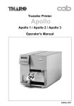
Apollo 1 / Apollo 2 / Apollo 3
Quick Operator's Guide
Edition 10/99
EU - Conformity Declaration
We declare herewith that as a result of the manner in which the machine designated below was
designed, the type of construction and the machines which, as a result have been brought on to the
general market comply with the relevant fundamental regulations of the EU Rules for Safety and Health.
In the event of any alteration which has not been approved by us being made to any machine as
designated below, this statement shall thereby be made invalid.
Description:
Thermal Transfer Printer
Type:
Apollo 1, Apollo 2, Apollo 3
Applied EU Regulations and Norms:
- EC Machinery Regulations
- Machine Safety
89/392/EEC,Appendix IIA
EN 292 T1 & T2:1991-11
- EC Low Voltage Regulations
- Data and Office Machine Safety
73/23/EEC
EN60950:1992 & A1:1993
EN 60950/A2:1993
- EC Electromagnetic Compatibility Regulations
- Threshold values for the Interference
of Data Machines
- Interference Resistance in both
Industrial and Small Plants
89/336/EEC
EN 55022 :1995-05
EN 50082-1: 1992-12
Signed for, and on behalf, the Manufacturer :
cab Produkttechnik Sömmerda
Sömmerda, 09.10.96
Erwin Fascher
Managing Director
Important Safety Information
1. Connect the printer only to an outlet with the correct voltage !
The printer is configured for either 230V or 115V power supply, which can be switched
using the input voltage selector at the back of the printer.
Connect only to a power outlet with a grounded contact.
2. The printer must only be connected to devices which have extra low voltage.
3. Power must be OFF before plugging in any accessory or connecting the printer to a
computer, etc. Also switch power off on all appliances before disconnecting.
4. Do not expose the printer to any moisture, or use in damp or wet areas.
5. The printer will operate with the cover open if necessary. This is not recommended, as
moving or rotating parts become accessible. Keep long hair, jewelry, loose clothes away
from the moving parts.
6. During the print process the printhead will become hot. Use extra caution when touching
the printhead.
7. Before starting any maintenance, switch the printer OFF and disconnect it from the
power supply.
8. Only qualified trained service technicians should attempt to repair your printer if
damaged or in need to repair.
cab - Produkttechnik GmbH
ENG-1
Overview of the Printer Components
1
2
3
4
5
6
7
12
8
9
13
10
11
1 - Display
2 - Function keys with
indicator LEDs
3 - Cover
4 - Ribbon shield
5 - Tear-off plate
6 - Peripheral port
7 - Printhead locking lever
8 - Ribbon take up hub
9 - Ribbon supply hub
10 - Media hub
11 - Media retainer
12 - Thermal printhead
13 - Label edge sensor
14 - Media rewind hub
15 - Memory card module slot
16 - Input voltage selector
17 - Power switch
18 - Power supply connector
19 - Serial interface port
20 - Parallel interface port
21 - Slot for fanfold paper
14
Apollo 1
Apollo 2
Apollo 3
15
15
20
16
19
17
16
18
17
18
21
ENG-2
20
19
21
cab - Produkttechnik GmbH
Connecting the Printer
Connection to Power Supply
The Apollo is designed for use with 230V A.C/ 50Hz (standard) or 115V A.C/60Hz.
F
Before connecting the printer to the power supply, make sure that the voltage
selected on the power supply module of the printer is the same as your main
power supply !
5
1
2
6
3
1
4
2
5
1 - Voltage selector
2 - Voltage selector
cover
3 - Power switch
4 - Power supply
connector
5 - Parallel interface port
6 - Serial interface port
3
6
4
Apollo 1/2
Apollo 3
To change the voltage setting, open the cover (2) and remove the voltage selector
from the power unit.
F
If you have changed the operating voltage of your printer the fuses need
replacing as stated below !
Apollo 1/2 :
230V - 2 x T 4A
115V - 2 x T 6.3A
Apollo 3 :
230V - 2 x T 1.6A
115V - 2 x T 3.15A
When delivered, the correct fuses for the pre-selected operative voltage are
installed. You will find the necessary fuses for the other voltage in the accessories
package.
Slide the voltage selector back into the power supply module so that the correct
voltage is visible in the lid window (2).
Connect the printer to a grounded outlet using the power cable supplied in the
accessories package.
Connection to a Computer
Select the required interface settings using the Setup procedure and connect the
printer to the computer by a suitable interface cable.
F
Make sure that all connected computers and their connecting cables are
correctly grounded.
cab - Produkttechnik GmbH
ENG-3
Print Media
The Apollo can be operated in direct thermal as well as thermal transfer mode.
For direct thermal mode, only use print material with a thermal-reactive coating.
In thermal transfer mode, not only standard paper labels are needed but also the
thermal transfer ribbon with a color surface. It is possible to pre-set in the setup
either the direct thermal mode or the thermal transfer mode, but the setting can be
changed for every print job via software.
The Apollo is able to print on labels and continuous paper from supply rolls.
The printer can also process fanfold label material.
Label/Tag Media Specification
G
H
K
I
E
D
A
B
C
L
M
F
Item
A
B
C
D
E
F
G
H
Label width
Width of silicon liner
Label length
Gap between labels
Label thickness
Thickness of silicon liner
Distance of the first printing position
from the edge of the silicon liner
Distance of the label sensor
from the edge of the silicon liner
MINIMUM
MAXIMUM
.5 (12)
.5 (12)
.2 (5)
.08 (2)
.0024 (.06)
.0024 (.06)
4.6 (116)
4.6 (116)
21.5 (546)*
21.5 (546)*
.01 (.25)
.01 (.25)
.08 (2)
.12 (3)
1.9 (48)
.2 (5)
.08 (2)
.2 (5)
.08 (2)
.2 (5)
.2 (5)
For special materials
I
K
L
M
Width of punch hole
Height of punch hole
Width of reflective mark
Height of reflective mark
* Apollo 3 : 37.2 (945), Apollo 3/300 :16.6 (427)
ENG-4
Dimensions in inches (mm)
cab - Produkttechnik GmbH
Loading Labels
1
9
11
2
10
8
3
4
5
7
6
1. Open the cover.
2. Lift the printhead by rotating the lever (1) clockwise until it stops.
3. Loosen the media retainer knurled screw (5), swing the media retainer (4)
backwards and place the label roll (2) onto the media hub (3).
4. Swing the media retainer (4) against to the media hub (3) and push it inwards
until it rests against the side of the label roll. Tighten the knurled screw (5).
5. Slide the media guide (8) into its outermost position.
6. Unroll a length of label stock from the media roll and feed it through as shown
in figure.
The solid line represents the feed path of outside-rolled labels, the broken line
of inside-rolled labels. The broken-dotted line shows the media path of fanfold
paper (6).
F
It is particularly important to ensure that the media strip slides properly
between the fittings of the adjustable label edge sensor (9).
7. Slide the media strip right through the space between the print roller and the
printhead until it comes out of the Apollo.
8. Slide the media guide (8) back towards the edge of the media strip.
9. Turn the lever (1) counter-clockwise until it stops and, thereby, lock the
printhead.
10. Close the cover.
cab - Produkttechnik GmbH
ENG-5
Loading Transfer Ribbon
2
3
4
5
1
6
7
2
3
4
5
6
7
1
Apollo 1
Apollo 2/3
1. Open the cover.
2. To lift the printhead, turn the printhead lever (1) clockwise until it stops.
3. Slide the roll of transfer ribbon (5) onto the ribbon supply hub (6) as far as
possible.
F
Pay attention to the side of the ribbon material which is coated with ink !
The inked side is generally the dull side. When the ribbon is inserted, the
inked side must face the opposite side of the printhead !
In figure, the solid line shows the path of inside wound ribbon, and the
broken line represents the path of outside wound ribbon.
4. Hold tight the ribbon supply hub (6) and rotate the knurled knob (7) clockwise
until it stops. That way the roll (5) will be attached at the ribbon supply hub (6).
5. Slide an empty cardboard core (2) onto the ribbon take up hub (3) and fix it by
turning the knurled knob (4) clockwise.
6. From the side, feed the transfer ribbon along the path as shown in
figure, then attach it to the core (2) using adhesive tape or a label.
7. Turn take up hub (3) in order to smooth and stretch the ribbon.
For Apollo 1, first turn the lever (1) to a central position between the locked and
unlocked positions.
8. Turn the lever (1) counter-clockwise until it stops and, thereby, lock the
printhead.
9. Close the cover.
ENG-6
cab - Produkttechnik GmbH
Adjustments Concerning the Labels
The printer can use a variety of media widths an thicknesses.
Beside it is possible to use materials which have punch holes and reflective marks
for the label recognition.
For this reason it is necessary to adapt the printer to the different materials by
only a few simple adjustments.
Adjustment of the Printhead Support
1
4
2a
3
1
2b
Apollo 1
4
2a
1
3
Apollo 2
2b
4
2b
3
2a
Apollo 3
When printing narrow labels (width less than 2.5 in or 60 mm), it is possible that the
printhead will come into direct contact with the drive roller. This will lead to
premature wear on the printhead. In addition, the printhead will be at a slight angle
to the label, thus, the uneven pressure may result in an inconsistent image density
from one edge of the label to the other.
To correct this problem, the printhead support (4) may be adjusted.
Adjust printhead support as follows :
1. Loosen the locking screw (2).
2. Move the locking screw (2) as required within the adjustment slot (3). This will
cause the cam shaped printhead support (4) to rotate, in effect, providing a
higher or lower base on which the printhead mounting (1) rests.
3. It is convenient to use the position 2a to printout large labels. The printhead
support (4) is total inactiv here.
4. By using small labels it is necessary to adjust the printhead support. In this
case insert a second strip of the label at the front side of the print roller. Now
slide the locking screw (2) as far as possible to position 2b in the adjustment
slot (3), until the printhead support (4) touches the printhead mounting (1).
Take away the second label strip.
5. Tighten the locking screw (2).
cab - Produkttechnik GmbH
ENG-7
Adjustment of the Label Edge Sensor
2
1
To accommodate a variety of print jobs, the position of the label edge sensor (1)
can be adjusted at right angles to the path of the paper feed.
It is important to ensure that the sensor is positioned in a way that the gaps
between the labels or the markings can be recognized by the photocell. (the
position of the sensor is marked by a notch in the sensor holder).
Adjust the sensor position using the knurled knob (2).
By turning the knob clockwise the sensor moves outwards, and by turning the knob
counter-clockwise the sensor moves inwards.
Adjustment of the Transfer Ribbon
1
2
4
3
If creases, lines or black patches appear in the print image resulting in a poor print
quality, this may be caused by wrinkles in the transfer ribbon (1). To remove the
wrinkles, the tension of the ribbon should be made even from the left to the right by
moving the ribbon shield (4) up or down.
1. Loosen the locking screw (3).
2. Shift the transfer ribbon shield (4) sideways into the direction of the wrinkle.
Moving it to the left will increase the tension on the left.
Use the scale (2) provided to monitor the adjustments made. If the screw is in
position "1", the tension is highest on the outside, and if it is in position "5", the
tension is highest on the inside.
3. After completing the adjustment, tighten the locking screw (3).
ENG-8
cab - Produkttechnik GmbH
Control Panel
The front control panel of the Apollo is fitted with 4 function keys with indicator
LEDs, and a 2x16 character digital LCD display.
The control panel display constantly provides the operator with the actual
information concerning the current printer mode and label processing. The indicator
LEDs support the information shown in the display by indicating which keys have to
be pressed. (e.g. in the event of a fault)
Function of the LED's
The illuminated LED's show the following printer states :
LED ONL
- Apollo is ready to print
LED FF
- Only if an applicator is installed : request to press the
key to
re-synchronize the paper feed after the appearance of an printer
error
LED CAN
- Error message ; print job can be cancelled by pressing the
key
LED PSE
- The printer is paused ; print job is temporarily interrupted by
pressing the
key or sending of a PAUSE-command via
interface; print job can be continued by pressing the
sending a PAUSE-OFF command
again or
- Error message ; LED is flashing, if there is a fault (e.g. "Out of
paper) which is easily correctable by the operator,following which
the printing process may be continued by pressing the
cab - Produkttechnik GmbH
key
ENG-9
Function of the Keys
The function of the keys is dependent on the System Mode of the printer :
System Mode ONLINE
ONL key
Switch into OFFLINE mode. (LED ONL off)
FF key
Provides label feed. The leading edge of the next label to be
printed is in print position.
CAN key
Deletes data of the previous print job in internal memory.
Following that, "Pause reprint" is not available.
(see PSE key)
PSE key
Repeats the print of the last label, after the previous print job has
been completed.
(only when setup parameter "Pause reprint" is on)
ONL key
+
CAN key
Pressing both keys together for at least 5 seconds will switch
into the SETUP mode.
(LED ONL off)
System Mode OFFLINE
ONL key
Switch into ONLINE mode. (LED ONL on)
FF key
Provides label feed. The leading edge of the next label to be
printed is in print position.
CAN key
Switch into LABEL FROM CARD mode.
(only if memory card is installed and formats are stored on it)
PSE key
Display shows current printer mode.
("Printer info")
System Mode PRINT
ENG-10
CAN key
short pressing :
Cancels the current print job.
Switch to the next job, which is available
in the input buffer
longer pressing (>1s): Cancels the current print job.
Clears the input buffer
(LED CAN blinks),
Switch into ONLINE mode.(LED ONL on)
PSE key
Interrupts the current print job.
Switch into PAUSE mode. (LED PSE on)
cab - Produkttechnik GmbH
System Mode PAUSE
FF key
Provides label feed. The leading edge of the next label to be
printed is in print position.
CAN key
short pressing :
PSE key
Continues the current print job.
Switch into PRINT mode. (LED PSE off)
Cancels the current print job.
Switch to the next job, which is available
in the input buffer
longer pressing (>1s): Cancels the current print job.
Clears the input buffer
(LED CAN blinks),
Switch into ONLINE mode.(LED ONL on)
System Mode LABEL FROM CARD
ONL key
Switch into OFFLINE mode.
FF key
For scrolling down within the file list stored on the card.
Reduces the quantity of labels to be printed.
CAN key
For scrolling up within the file list of the card.
Increases the quantity of labels to be printed.
PSE key
Confirms file selection.
Moves the cursor to the right when setting the quantity of labels
to print.
Switch into PRINT mode.
cab - Produkttechnik GmbH
ENG-11
Self Test
Power On System Test
When switched on, the Apollo automatically performs an internal system test.
If the test is completed successfully, the Apollo proceeds to the ONLINE mode, or
otherwise the printer switches to system mode FAULT - IRRECOVERABLE.
The top line of the display shows the version of the printer :
" **** APOLLO 1 **** ".
The bottom line of the display shows the numbers "123456" one after the other
depending on the progress of the several test steps.
Test Print
To prepare a test print, load media (labels or continuous paper) which extends over
the entire print width of the Apollo.
If you want to perform the test print in thermal transfer mode, also use transfer
ribbon of the maximum width.
F
During test print, the Apollo will not sense any label gaps. The length of the
printout will be about 9 in (230 mm).
To initiate a self test printout, press the
key when switching on the printer
and keep it pressed down until the system test is completed.
The display shows "Test print", and the Apollo will print an internal test sample
which contains a variety of information about the configuration of the printer as well
as the results of the internal test.
The test printout can also include a range of hardware errors which have occurred
previously, even if they have disappeared again. This information is important for
service purposes and can only be deleted by Technical Support.
The information in the printout is also useful for checking the print quality, such as
differences in the blackness left/right, missing ink dots, etc. It is recommended you
carry out a print test immediately after receiving the printer.
After completing the test print, the Apollo will run the system test once again.
Then, the printer proceeds to ONLINE mode.
To cancel the test print press the
ENG-12
key.
cab - Produkttechnik GmbH
Explanation of the Self Test Printout
Firmware-Version
Setup and status
informationen
Bar code with
test information
Available
fonts
Test pattern
Setup and Status Information
Country
:
Setting of the "Country" parameter
Print mode
:
Setting of the "Transfer print" parameter
Label sensor
:
Setting of the "Label sensor" parameter
Interface
:
Setting of the "Interface" parameter
Cut Position
:
Setting of the "Cut position" parameter
Peel Position
:
Setting of the "Peel position" parameter
Printhead Pos. :
cab - Produkttechnik GmbH
Setting of the "Printhead position" parameter
ENG-13
Heat level
:
Setting of the "Heat level" parameter
Test result
:
Result of the system test. Any errors will be shown coded
as four digit hexadecimal numbers.
/C shows when the setup has been altered from the
defaults. (Apollo 1 and Apollo 2 only)
For Apollo 3, the letter behind the "/" sign indicates the
state of modification of the hardware. (board)
Operative time :
Cumulative operating time of the printer
Number of labels : Cumulative amount of printed labels
Thermal transfer :
Cumulative length of printed material in thermal transfer
mode
Thermal direct :
Cumulative length of printed material in direct thermal mode
Date/Time
:
Setting of system date and system time
Character set
:
Setting of the "Character set" parameter
Temperature
:
Printhead temperature
Heat voltage
:
Current value of heat voltage
(approx. 24V; Apollo 3/300 approx. 20V)
Brightness
:
Service information on brightness used at gap sensor
Peripheral device : Type of device connected to peripheral port
Memory card
:
Type and capacity of memory card (PCMCIA/PC card)
Monitor Mode/ ASCII Dump Mode
If programming directly, the monitor mode provides a method to print control
sequences which were received at the interface. The commands will be printed in
text format depending on the selected character set. Error messages will be
printed directly behind the fault, e.g. for unknown commands.
In monitor mode, the Apollo will not recognize gaps between labels nor control the
ribbon feed.
To start the monitor mode, press the
key while switching on the printer,
and keep it pressed down until the system test is completed. The display shows
"ASCII Dump Mode".
To cancel ASCII Dump mode, press the
key.
In monitor mode, the print of data will be started after every four lines of data
received. Therefore, in some cases, the last lines of the label have to be retrieved
by pressing the
ENG-14
key.
cab - Produkttechnik GmbH
Setup
Using the setup mode, the configuration of the Apollo may be customized to suit
specific requirements. Initial setup should be performed when operating the printer
for the first time. Changes which become necessary to process different print jobs,
e.g. when different materials are used, can mostly be accomplished by changing
the software settings.
Start of Setup Mode
This mode is initiated by either simultaneously pressing the
key and the
key when switching on the printer and keep them pressed down until the
system test is completed, or in ONLINE mode, press the same two keys down for
at least 5 seconds.
Each time a parameter setting has been changed, there will be a request for
confirmation. There will not be a general request before leaving the setup mode.
Leaving the Setup Mode
The setup mode can be left at any point by pressing the
parameters will be saved.
key. The confirmed
If an already confirmed setting is not desired any more, switch off the printer during
the setup mode to cancel changes.
Restore the Default Setup
To return to the original factory default settings, press all three keys, the
the
key, and the
key,
key simultaneously and keep them pressed down until
the display shows "--- RESTORE ---".
Function of the Keys in the Setup Mode
ONL key
Stores the chosen settings of the setup parameters and
completes the SETUP mode.
(i.e. switch into ONLINE mode/ LED ONL on)
FF key
Skips to next setup parameter.
Reduces numerical setup values.
CAN key
Skips to previous setup parameter.
Increases numerical setup values.
PSE key
Confirms selected settings for parameters.
cab - Produkttechnik GmbH
ENG-15
Overview of the Setup Parameters
Country
Deutschland
Belgie
Country setting :
France
Suomi
Transfer Print
On
Bottom-Reflect Top-Reflect*
Setting of the interface type
at serial interfaces setting of the baud rate
and the protocol or network address
RS-422
Baud rate
Protocol
Using the optional present sensor, the parameter allows you to alter the
position of the dispensed label relative to the dispense edge. If the peel
position value is positive, the label will be removed further.
- x.x mm
± x.? mm
± ?.x mm
The parameter defines the location of the print image on the label in the
transport direction.
- x.x mm
± x.? mm
± ?.x mm
Heat level
+x
ENG-16
Centronics
- x.x mm
± x.? mm
± ?.x mm
Printhead pos.
+ x.x mm
± x.? mm
± ?.x mm
RS-485
Baud rate
Network address
Using the optional cutter, the parameter allows you to alter the distance
between the cutting edge and the rear edge of the label. If the cut position
value is positive, the media will be advanced before it is cut.
Peel position
+ x.x mm
± x.? mm
± ?.x mm
Suisse
Danmark
Setting of the label recognizing method
* Top-Reflect at Apollo 1/2 only
Cut position
+ x.x mm
± x.? mm
± ?.x mm
Schweiz
Ceska republica
Off
Interface
RS-232C
Baud rate
Protocol
USA
España
Setting of the print mode : Direct Thermal or Thermal Transfer
Label sensor
Gap sensor
United Kingdom
Italia
LCD display language
Formats of date and time
Measuring unit ( USA: inch, all other: mm)
Basic adjustment of the darkness (depending on the printhead)
"-9" indicates the lightest and "+9" indicates the darkest setting.
-x
cab - Produkttechnik GmbH
Printer info
The parameter provides information about the firmware, the cumulative
length of printed media and the number of operating hours.
Version xxxxx xxx m / xxx h
Set date
DD.xx.xxxx
Setting of the system date (day, month, year)
xx.MM.xxxx
Set time
hh.xx.xxxx
xx.xx.YYYY
Setting of the system time (hour, minute, second)
xx.mm.xx
Character set
xx.xx.ss
Setting of the character set
Windows 1252 Windows 1250 ISO 8895-1
Codepage 850
EBCDIC
Macintosh
Codepage 852
ISO 8895-8
Format Card
No
Command to format a PCMCIA card
Yes
Copy Memory Card
Yes
Command to copy a PCMCIA card
No
Backfeed
Setting of the backfeed mode in the cut or peel-off mode
head lift-off
head down
smart
always
Debug mode
Off
Selection, if the backfeed should be avoided if possible
or always be carried out
The "Debug mode" represents a tool for the firmware programmer only
On
Tear-off positio
Off
Selection, if the printhead is raised or not raised
from the printhead during the backfeed (Apollo 1 only)
If the parameter is active, an additional feed forwards will take place after
completion of the print job. This makes it possible to cut off the last label
at the tear-off plate.
On
Pause reprint
If the paramter is active, after completion of a print job, the print of the last
label may be repeated by pressing the
On
cab - Produkttechnik GmbH
key.
Off
ENG-17
Options
External Rewinder
To handle large print jobs, an external rewinder is available which allows you to
rewind complete rolls of label material.
Delivery Contents
The rewinder is packed separately from the printer.
F
Please keep the original packaging in case the rewinder must be returned !
The following components are included in the package :
1
2
10
1
2
3
4
-
5
6
7
8
9
10
-
3
4
5
6
7
8
9
Rewinder
Guide bar
Cylinder screw M5x10 incl. washer A5.3
Printer adapter
(upper adapter plate, lower adapter plate, 2 knurled screws M4x6)
Hexagonal wrench (.16 in or 4 mm)
2 Rewind axle adapters, with a diameter of 3 in or 75 mm
2 x 1A Fuses (for use at 115V)
Power cable
Clamp
Flange
Safety Instructions
F
ENG-18
The printer must be powered OFF before mounting the rewinder.
During operation, the rotating axle is openly accessible !
Therefore, keep long hair, loose clothes, and jewelry away from the moving parts !
Before connecting the rewinder to the power supply, make sure the voltage
selected on the power module corresponds with the supply voltage !
cab - Produkttechnik GmbH
Mounting the Printer Adapter
In order to operate the external rewinder, an adapter unit has to be mounted on to
the Apollo.
4
5
1
2
3
6
7
1. Attach upper adapter plate (2) to the lower adapter plate (3) using the knurled
screws (1). Put the screws through the circular holes in the upper adapter
plate.
2. Rotate the accessory lock/release lever (7) counter-clockwise until it stops.
3. Remove the tear-off plate (4) from its mountings (6).
4. Insert the printer adapter plate (5) into the mountings (6).
5. Turn the lock/release lever (7) clockwise until it stops.
6. Adjust the lower adapter plate (3) vertically until only a space of about .08 in or
2 mm is left between the adapter plate and the standing area.
7. Tighten the screws (1).
Mounting the Guide Bar
1
2
3
4
1
2
3
4
-
Rewinder
Upper threaded hole
Guide bar
Screw (incl. washer)
Using the hex screw (4) and washer provided, secure the guide bar (3) into the
upper one of the two threaded holes (2) located on the inside of the rewinder's side
cover. A hexagonal wrench is provided.
cab - Produkttechnik GmbH
ENG-19
Selecting the Method of Rewinding
The external rewinder allows rewinding of labels in both ways, inside and outside
winding.
5
Set the switch (5) to the required method of rewinding :
- Rewind with labels on the outer side of the silicon liner
- Rewind with labels on the inner side of the silicon liner
Connecting the Rewinder to the Power Supply
The rewinder operates with a supply voltage of 230V/ 50Hz or 115V/ 60Hz.
F
Before connecting the rewinder to the power supply, make sure that the
voltage selected on the power supply module is the same as your main power
supply !
1 - Power supply
connector
2 - Power switch
3 - Voltage selector cover
1
2
3
The current voltage setting of the power module is visible in the lid window (3).
F
If you have switched the operating voltage of your rewinder you need to
replace the fuses. For the standard setting of 230V, two fuses rated at
500mAT must be used. For operation at 115V, two fuses rated at 1AT must be
used. (Both types of fuses are shipped with the rewinder, one of which is
installed depending on the voltage setting.)
To alter the voltage, open the cover (3) and remove the voltage selector. Replace
the fuses as explained above. Slide the voltage selector back into the power
supply module so that the correct voltage is visible in the lid window.
Connect the rewinder to a grounded outlet using the power cable supplied in the
accessories package.
ENG-20
cab - Produkttechnik GmbH
Rewinding Operation
1
2
3
7
6
1
5
4
6
10
9
8
5
4
Rewinding Directly onto the Rewind Axle
F
1. Attach the rewinder to the Apollo by positioning the metal posts on the bottom
of the rewinder (5) into the holes of the adapter plate (4).
2. Feed the label strip over the guide bar and under the roller onto the rewinder
axle (6) as shown in the left upper figure. Considering the required method of
rewinding, secure the label strip appropriately to the rewinder axle (6) by sliding
the clamp (7) over the label strip with the clamp set in the groove. (the broken
line shows the path of inside rolled labels)
Ensure that the label strip is even with the disc (1).
4. Slide the clamp (7) as far as possible towards the disc (1).
5. Slide the flange (3) onto the rewind axle (6) so that it slightly touches the label
strip. The label strip must be able to move slightly between the disc and the
flange.
6. Tighten knurled screw (2) in the flange (3).
7. Switch the rewinder ON.
Caution ! When switched ON, the rewinder immediately starts rotating !
Rewinding on to 3 in (75 mm) Cardboard Rolls
F
1. Use a cardboard roll (8) which is about .04 in (1 mm) wider than the label strip.
2. Attach the rewinder to the Apollo by positioning the metal posts on the bottom of
the rewinder (5) into the holes of the adapter plate (4).
3. Mount the first axle adapter (9) onto the rewinder axle (6) and slide it up to the disc
(1). Tighten knurled screw (10).
4. Mount the second adapter onto the rewinder axle (6). Slide it towards the first
adapter until the clearance between the edge of the adapter and the disc (1) is a
little less than the width of the cardboard roll (8). Tighten knurled screw (10).
5. Slide the cardboard roll (8) over the two adapters (9) until it is touching the disc (1).
6. Feed the label strip over the guide bar and under the roller as shown in the right
upper figure up to the cardboard roll (8).
7. Using adhesive tape or a label, affix the end of the label strip to the cardboard roll
(8). (the broken line shows the path of inside rolled labels)
8. Slide flange onto the rewind axle (6) until it stops at the cardboard. Tighten
knurled screw.
9. Switch the rewinder ON.
Caution ! When switched ON, the rewinder immediately starts rotating !
cab - Produkttechnik GmbH
ENG-21
Rewind Guide Plate
The optional rewind guide plate for printers with internal rewinder allows you to
rewind small print jobs inside the printer.
The Apollo is delivered with a mounted tear-off plate (4). For internal rewinding,
the tear-off plate has to be replaced with the rewind guide plate (3) :
1.
2.
3.
4.
Turn the lever (1) counter-clockwise until it stops.
Remove the tear-off plate (4) from the mounting holes (2).
Slide the rewind guide plate (3) into the mounting holes (2).
Turn the lever (1) clockwise until it stops.
5
6
7
8
9
4
3
2
1
3
15 14 13 12
11 10
5. Lift printhead by turning the lever (5) clockwise until it stops.
6. Loosen knurled screw (9), then swing the media retainer (8) backwards.
7. Place the media roll (6) onto the media hub (7). Swing the media retainer (8)
to the media hub and inwards until it rests against the side of the roll. (roll will
slightly be slowed down when unwound) Tighten knurled screw (9).
8. Slide the two media guides (13/14) outwards to their outermost position.
9. Unroll a length of stock from the media roll and feed along as shown in the right
upper figure. It is particularly important to ensure that the media strip slides
properly between the fittings of the adjustable photocell assembly (15).
10. Feed the media strip between the print roller and the thermal printhead, and
then over the rewind guide plate (3) to the internal rewinder (12).
11. The internal media rewind hub (12) is fitted with an expanding axle that
contains clamps (10) for securing the media. Slide the media strip from
underneath the rewinder clamps (10) to the disc. Fasten the media strip to
the axle by holding the rewinder and rotating the knurled knob (11) clockwise
until it stops. To tighten the media, rotate rewinder counter-clockwise.
12. Slide the media guides (13/14) towards the edge of the media strip.
F
ENG-22
13. Lock the printhead by turning the lever (4) counter-clockwise until it stops.
If you do not use the printer for an extended period of time, lift the printhead to
avoid possible flattening of the print roller.
cab - Produkttechnik GmbH
Cutter Assembly
With the optional cutter assembly installed, labels or endless media may be cut
off immediately after being printed.
The cutter assembly is delivered in a separate package. Please keep the original
packaging in case the cutter must be returned !
Installing and Operation
F
The printer must be switched OFF before mounting the cutter !
The cutter may be used only when mounted onto the Apollo !
1
5
4
3
2
6
4
The Apollo is delivered with the tear-off plate (5) installed.
Before mounting the cutter, the tear-off plate has to be removed :
1. Switch the printer OFF.
2. Feed the label stock into the Apollo in such a way that the leading edge of the
first label is protruding slightly beyond the printhead (1).
3. Turn the printhead lever (2) counter-clockwise until it stops.
4. Remove the tear-off plate (5) from the guide holes (3).
5. Slide the cutter (4) into the guide holes (3) .
6. Turn the lever (2) clockwise until it stops.
7. Connect the cutter cable (6) to the 15 pin peripheral port on the front of the
Apollo.
8. Switch the printer ON. The cutter will perform a synchronized cutting cycle.
9. Press the
key. The printer will feed one unprinted label forwards which
will be cut off by the cutter. The label stock feed is now synchronized for the
start of the printing process.
10. Activate the cutter function by selecting the cut mode in the software (in direct
programming use the "C" command).
cab - Produkttechnik GmbH
ENG-23
Present Sensor
The optional present sensor in connection with printers with internal rewinder
allows for on-demand label dispensing. That means, the labels are removed from
the silicon liner immediately after printing, and then available in a dis-pense
position ready for further processing.
The present sensor (2) consists of two components, the dispense edge (18) and
the present sensor photocell (6). The presence of a label (19) in dispense position
is observed by the photocell. Through its connection to the peripheral port of the
Apollo, the signal pauses the print of the next label until the label in the dispense
position is removed.
F
Note : When editing or creating labels in demand mode, make sure that the part of
the label which lies directly underneath the photocell is only colored (black) to a
maximum of 50%. Higher blackening/ density print may cause malfunctions of the
sensor.
Montage des Spendesensors
1
2
3
4
5
6
The Apollo is generally shipped with the tear-off plate (1) mounted. When
operating in dispense mode, the tear-off plate has to be replaced with the present
sensor (2) :
1. Turn lever (4) counter-clockwise until it stops.
2. Remove the tear-off plate (1) from the mounting holes (3).
3. Slide the present sensor (2) into the mounting holes (3).
4. Turn lever (4) clockwise until it stops.
5. Connect the cable (5) of the present sensor (6) to the 15 pin peripheral port of
the Apollo.
ENG-24
cab - Produkttechnik GmbH
Inserting the Labels for Peel-off
7
8
9
10
11
6
20
19
18
17 16 15 14
13
12
1. Lift the printhead by turning the lever (7) clockwise until it stops.
2. Loosen the knurled screw (11) and swing media retainer (10) backwards.
3. Place the media roll (8) onto the media hub (9). Swing the media retainer (10)
to the media hub and inwards until it rests against the side of the roll. Tighten
the knurled screw (11).
4. Slide the two media guides (15/16) to their outermost position.
5. Unroll a length of media stock and feed it through the Apollo as shown in
figure. It is particularly important to ensure that the media strip slides properly
between the adjustable fittings of the photocell assembly (17).
6. Feed the media strip between the print roller and the thermal printhead, and
then over the dispense edge (19) up to the internal rewinder (14).
7. Slide the media strip from underneath the rewinder clamps (12) to the disc.
Fasten the media strip to the axle by holding the rewinder (14) and rotating the
knurled knob (13) clockwise until it stops. To tighten the media, rotate rewinder
counter-clockwise.
8. Slide the two media guides (15/16) against the edge of the media strip.
9. Lock the printhead by turning the lever (7) counter-clockwise until it stops.
10. Activate the peel-off function by selecting the peel-off mode in the software (in
direct programming use the "P" command).
F
If you do not use the printer for an extended period of time, lift the printhead to
avoid possible flattening of the print roller.
cab - Produkttechnik GmbH
ENG-25
Cut-/Peel-off Adapter
By using the cut/peel-off adapter it is possible, to operate the Apollo with cutter
assembly or present sensor in a special mode, where the print of one label can be
started by an external start signal.
In the peel-off mode, after removing a label from the peel-off position the use of the
adapter avoids the immediate print of the next label.
In the cut mode the print job can be divided in single prints.
In both cases, a label will only be printed, if it is required (cut/peel-off on demand).
Connectors
Front side
Back side
1 2 3 -
1
2
15-pin SUB-D connector for cutter
assembly or present sensor
9-pin SUB-D connector for an external
release switch
15-pin SUB-D plug to connect the
adapter to the peripheral port of the
Apollo
3
Pin Assignment of the 9-pin SUB-D Connector
Pin 5
Pin 9
Pin 1
Pin 6
Pin 1/2 -
Optocoupler inputs. A short impuls of 24V= at the pins (+ at pin 1, - at pin 2)
releases the print of one label (external start signal).
The start impuls has to be shorter than the print time of the label. The current is
internally limited to 10 mA.
with present sensor :
the print is released only, if there is no label in the
presentation position
with cutter assembly : the printed label will be cut
Pin 3/4 -
Transistor outputs of an optocoupler (pin 3 - collector, pin 4 - emitter). If the
adapter is used with the present sensor, the state of the transistor shows the
presence of a label in the peel-off position. If there is a label, the transistor is
blocked so that no current can flow between the pins.
F
At connecting the pins 3 and 4 the current has to be limited externally to
10mA. Otherwise the output will be destroyed.
ENG-26
cab - Produkttechnik GmbH
Pin 5/6 -
Pin 5 : Internal operating voltage +24V ; Pin 6 : Ground
The operating voltage can be used to generate the external start signal with a
switch.
The use of this voltage for other purposes is prohibited.
Pin 7/8/9 - n.c.
Inputs and outputs are designed with optocouplers, i.e. they are potential free in
relation to the Apollo. The isolation voltage is 500 V. The voltage at the outputs
should not be higher than 30V.
Installation and Operation
1
2
3
4
5
6
7
1. Switch OFF the printer.
2. Connect the 15-pin SUB-D plug (2) at the back side of the cut/peel-off
adapter (1) to the peripheral port (3) of the Apollo.
3. Mount the cutter assembly (7) or the present sensor as described in the
previous chapters contact the cable (6) to the 15-pin SUB-D connector (5)
at the front side of the cut/peel-off adapter.
4. Plug the cable of the external release switch to the 9-pin SUB-D connector
(4).
F
5. Switch ON the printer.
Make sure, that the external release switch is open (no voltage at
Pin 1 of the 9-pin connector) when the printer is switched ON.
6. Start a print job in the cut or peel-off mode.
7. Release the print of single labels by actuating the external switch.
cab - Produkttechnik GmbH
ENG-27
Memory Cards
The printers of the Apollo series provide an option for using memory cards to
permanently save graphics, fonts, complete label formats, or database information.
Data transfer may be performed via interface. Alternatively, the printer is able to
read from cards which has been written on in PC card drives of lap-tops or other
computers, etc.
The Apollo is able to read from PCMCIA version 2.1 compatible sRAM cards or
Flash-EPROM cards. The maximum memory capacity for Apollo 1/2 is 4
MegaByte, and for Apollo 3 16 MegaByte.
Installation of the Memory Card
1
2
3
4
The front side of the memory card (1) is usually marked by the inscription "MEMORY
CARD", and an arrow (2) representing the direction of inserting the card into the drive.
There is also an arrow (4) impressed into the frame of the memory card slot of the
Apollo.
Insert the card (1) into the slot (3) so that the front of the card faces the arrow (4).
At the connecting side of the card there are different guides on the top and the bottom
which make it impossible to insert the card incorrectly.
ENG-28
cab - Produkttechnik GmbH
Printing from a Memory Card
F
Using a memory card provides the opportunity to print without a connection
of the Apollo to a computer.
Follow the instructions below, after the card has been installed and the printer has
been switched ON :
1. Switch printer into OFFLINE mode by pressing the
2. After pressing the
key.
key, the file name of the first label saved on the card
will be shown.
3. Using the
key and the
key, you may scroll up and down the
contents of the card. Confirm the selection by pressing the
key.
4. If you have chosen a label with a set number of labels to print, the Apollo will
instantly start printing.
5. For labels with a variable number of labels, the top line of the display shows
"Number of labels", the bottom line shows "00001" with the first figure flashing.
(cursor)
Using the
key and the
may be altered. By pressing the
key, the figure at the position of the cursor
key the cursor can be moved on to the
next figure. After confirming of the last figure, the Apollo starts to print.
6. To pause the selection of a label or the input of the number of labels you may
press the
key.
The data saved on the card is also accessible via interface and computer.
cab - Produkttechnik GmbH
ENG-29
Keyboard Adapter
The keyboard adapter option offers to connect the Apollo to a standard PC
keyboard or any other compatible input device (e.g. a bar code scanner) via its
serial interface. Using the keyboard, print jobs of an internal PC card may be
loaded and variable data may be altered. Input data requests as well as data
received from the keyboard will be shown in the display of the Apollo.
The keyboard adapter is designed for use with all keyboards which fulfill the
following requirements : MF-2 compatible, having a 5pin DIN plug, supporting code
set 3, and also operating with a maximum of 15 kBaud.
F
The current consumption of the connected keyboard or scanner must not exceed
100 mA.
Installation of the Keyboard Adapter
1 - 25 pin SUB-D plug
2 - 5 pin DIN connector
1
2
1. Change the interface setting to "RS232C, 9600 Baud, RTS/CTS" and
confirm.
2. Connect the 25 pin plug (1) of the keyboard adapter to the serial interface
connector at the rear of the printer.
Make sure that the printer is switched OFF !
3. Connect the keyboard to the 5 pin DIN connector (2) of the keyboard
adapter.
ENG-30
cab - Produkttechnik GmbH
Key Assignment
The Apollo can easily be adjusted to the keyboard configuration of the particular
country by using the setup parameter "Country". For each of the available settings
the Apollo has a different table of key assignment, which, generally, complies with
the assignment under Microsoft DOS.
The [ALTGR] key has no function. Therefore, all signs which are located on the
right hand side of the key opposite of the normal characters (e.g. { } [ ] \) can be
generated by pressing the [ALT] key. A few of the other special signs (e.g. ¨ × ÷)
may also be generated the same way.
Other special characters (e.g. ñ ç œ) can be generated by inserting two characters
one after the other, where the second input is a combination with the [ALT] key.
Some of the special characters cannot be shown in the display of the printer. In
that case, the Apollo will use a character which looks similar to the required
character.
F
When using a scanner, the character set of the scanner has to be the same as
used by the Apollo.
Special Key Functions
[F1]
To enter the list of labels stored on the memory card.
[F2]
To repeat the print of the last label. (as command A 1 CR)
[F3]
To repeat the print of the last label including a new enquiry for variable data.
[Shift]+[F5]
To start the monitor mode/ASCII dump mode.
[Shift]+[F6]
To start the self test printout.
[F7]
Printer Info Display
[F8]
Form feed
[ENTER] or
[RETURN]
Without a current print job : to switch between ONLINE and OFFLINE;
While processing a print job : to confirm the data input.
[ESC]
To cancel the data input.
(while printing same effect as CANCEL)
[SPACE]
While printing same effect as PAUSE.
[Shift]+[Del]
To delete the input line.
[á],[â]
To scroll up/down the list of labels on the memory card.
cab - Produkttechnik GmbH
ENG-31
Error Messages/ Problem Solution
The Apollo is equipped with a comprehensive self diagnostic system which will
indicate errors in the display of the printer. Also, the operator will be informed by
the LEDs whether the fault is correctable and will, therefore, allow to continue the
current print job after corrections (e.g. "Out of paper"), or the fault may require you
to cancel the current print job.
Correctable Errors
While processing a print job, an error has occured which may be corrected by the
operator, and also allows you to continue the print job after fault correction.
The top line of the display shows alternately the type of fault and the total of the
remaining labels of the current print job.
The LED CAN is switched on, the LED PSE is flashing.
Function Keys
CAN key
PSE key
short pressing :
Cancels the current print job.
Switch to the next job, which is available
in the input buffer
longer pressing (>1s): Cancels the current print job.
Clears the input buffer
(LED CAN blinks),
Switch into ONLINE mode.(LED ONL on)
Continues current print job after error correction.
Switch into PRINT mode.
(LED ONL on, LED CAN off, LED PSE off)
Irrecoverable Errors
While switching on the printer or during printing, a fault has occured which cannot
be cleared by the operator without cancelling the current print run.
(e.g. hardware fault)
The display shows the type of fault. The LED CAN is flashing.
Function Keys
CAN key
ENG-32
Cancels the current print job.
Switch into ONLINE mode.
(LED ONL on, LED CAN off, LED PSE off)
If ONLINE mode cannot be entered, switch printer off and on
again.
If the fault remains again, contact Technical Service
cab - Produkttechnik GmbH