1
Bulletin 2583-M1/USA
Installation Guide
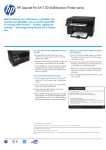
Series D1FX
30 Design
Effective: December 11, 1995
WARNING
FAILURE OR IMPROPER SELECTION OR IMPROPER USE OF THE PRODUCTS AND/OR SYSTEMS DESCRIBED HEREIN OR RELATED ITEMS CAN CAUSE DEATH, PERSONAL
INJURY AND PROPERTY DAMAGE.
This document and other information from Parker Hannifin Corporation, its subsidiaries and authorized distributors provide product and/or system options for further investigation by users
having technical expertise. It is important that you analyze all aspects of your application and review the information concerning the product or system in the current product catalog. Due
to the variety of operating conditions and applications for these products or systems, the user, through its own analysis and testing, is solely responsible for making the final selection of
the products and systems and assuring that all performance, safety and warning requirements of the application are met.
The products described herein, including without limitation, product features, specifications, designs, availability and pricing, are subject to change by Parker Hannifin Corporation and its
subsidiaries at any time without notice.
Offer of Sale
The items described in this document are hereby offered for sale by Parker Hannifin Corporation, its subsidiaries or its authorized distributors. This offer and its acceptance are governed
by the provisions stated in the "Offer of Sale".
Copyright 1995, Parker Hannifin Corporation, All Rights Reserved
II
Parker Hannifin Corporation
Hydraulic Valve Division
Elyria, Ohio 44035 USA
Proportional Directional Control Valves
Series D1FX, 30 Design
Contents
Technical Information .......................................................................................................................................... 1
General Description ......................................................................................................................................... 1
Features .......................................................................................................................................................... 1
Operation ........................................................................................................................................................ 1
Specifications .................................................................................................................................................. 1
Functional Description (Version AJ) .................................................................................................................. 2
Configuration Definition ................................................................................................................................... 2
Installation ....................................................................................................................................................... 2
Standard Driver — Version AJ ......................................................................................................................... 2
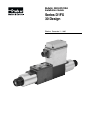
Figure 1: Version AJ Functional Block Diagram ...................................................................................... 2
Wiring & Initial Startup (Version AJ) .................................................................................................................. 3
Initial Startup ................................................................................................................................................... 3
Interface Wiring, 6 Pin I/O Connector ............................................................................................................. 3
Figure 2: Version AJ Board Setup ........................................................................................................... 3
Figure 3: Interface Wiring Diagram, Version AJ ...................................................................................... 3
Functional Description (Version BJ) .................................................................................................................. 4
European Version BJ ....................................................................................................................................... 4
Figure 4: Version BJ Functional Block Diagram ...................................................................................... 4
Wiring & Initial Startup (Version BJ) .................................................................................................................. 5
Initial Startup ................................................................................................................................................... 5
Interface Wiring, 7 Pin I/O Connector ............................................................................................................. 5
Figure 5: Version BJ Board Setup .......................................................................................................... 5
Figure 6: Interface Wiring Diagram, Version BJ ...................................................................................... 5
Functional Description (Versions CJ & CK) ...................................................................................................... 6
External Closed Loop Feedback — Versions CJ & CK ................................................................................... 6
Figure 7: Version CJ Functional Block Diagram ..................................................................................... 6
III
Parker Hannifin Corporation
Hydraulic Valve Division
Elyria, Ohio 44035 USA
Proportional Directional Control Valves
Series D1FX, 30 Design
Contents
Wiring & Initial Startup (Versions CJ & CK) ...................................................................................................... 7
Initial Startup ................................................................................................................................................... 7
Interface Wiring, 6 Pin I/O Connector ............................................................................................................. 7
Figure 8: Versions CJ & CK Board Setup ............................................................................................... 7
Figure 9: Interface Wiring Diagram, Versions CJ & CK .......................................................................... 7
Functional Description (Versions DJ & DK) ...................................................................................................... 8
Standard Driver with Deadband Eliminators — Versions DJ & DK .................................................................. 8
Figure 10: Version DJ Functional Block Diagram ................................................................................... 8
Wiring & Initial Startup (Versions DJ & DK) ...................................................................................................... 9
Initial Startup ................................................................................................................................................... 9
Interface Wiring, 6 Pin I/O Connector ............................................................................................................. 9
Figure 11: Versions DJ & DK Board Setup ............................................................................................. 9
Figure 12: Interface Wiring Diagram, Versions DJ & DK ........................................................................ 9
Options & Adjustments ..................................................................................................................................... 10
Spool Position Monitoring .............................................................................................................................. 10
LVDT Null ...................................................................................................................................................... 10
Reference Voltages (AJ, CJ, CK, DJ, DK) .................................................................................................... 10
Manual Overrides .......................................................................................................................................... 10
Min Adjustments (BJ, CJ, CK, DJ, DK) ......................................................................................................... 10
Max Flow Adjustments (AJ, BJ, DJ, DK) ........................................................................................................11
Max Gain Adjustments (CJ, CK) ....................................................................................................................11
Bias ...............................................................................................................................................................11
Current or PLC Command ..............................................................................................................................11
Trouble-Shooting ............................................................................................................................................... 12
Installation Information ..................................................................................................................................... 13
Ordering Information ......................................................................................................................................... 14
Offer of Sale ........................................................................................................................................................ 15
IV
Parker Hannifin Corporation
Hydraulic Valve Division
Elyria, Ohio 44035 USA
Proportional Directional Control Valves
Series D1FX, 30 Design
Bulletin 2583-M1/USA
Technical Information
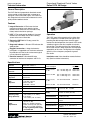
General Description
The D1FX Series of proportional directional control
valves provide variable output flow in response to
voltage or current command signals. The valves are
fully integrated units with on-board electronics and a
spool position feedback device.
Features
•
Integral Electronics ¾ Eliminates the time
consuming and often costly electrical wiring
between valve and driver card. Provides a fully
factory tested valve/driver package.
•
LVDT ¾ The spool position feedback is located
between the valve body and coil thus allowing
access to the manual overrides.
Operation
•
Electronic LVDT Null ¾ Factory preset. No
nulling required.
•
Diagnostic Indicator ¾ Bi-color LED indicates the
spool position.
•
Rugged Construction ¾ Integral electronics
packaged in a rugged die cast aluminum enclosure
for protection from the harsh environments typical
in many industrial applications.
The D1FX spool shifts proportionally in either direction in response to variable command signals; thus
providing the desired output flow. Once the spool
reaches the desired position, the internal LVDT sends
a feedback signal to the drive amplifier to maintain
that position. The closing of the inner control loop in
this manner results in lower hysteresis and improved
repeatability of the valve. The high dynamic amplifier
gives this valve a frequency response of greater
than 20 Hz.
•
Electrical Interface ¾ Standard MS style
connector for interface to computers and PLC's.
Installation note: Valve should be mounted horizontally. (See Installation Information.)
Specifications
Interface
Input
Impedance
NFPA D03, CETOP 3
Command Signal
Maximum Pressure
315 Bar (4500 PSI)
Max. Tank Line
Pressure
35 Bar (500 PSI)
Version AJ, BJ,
CJ, DJ
0 to ± 10 VDC Dbl. Coil
0 to + 10 VDC Sgl. Coil
100 k ohms
100 k ohms
Flow
Up to 38 LPM (10 GPM)
Version CK, DK
Frequency
Response
> 20 Hz with 10% CMD at 50%
spool stroke
0 to ± 5 VDC Dbl. Coil
0 to + 5 VDC Sgl. Coil
100 k ohms
100 k ohms
Versions AJ, BJ, CJ, DJ:
Full Shift, <60 mS
Versions CK, DK:
Full Shift, <70 mS
Version AJ, BJ,
CJ, DJ
4 to 20 mA Command
499 ohms
Step
Response
Version CK, DK
4 to 20 mA Command
249 ohms
Repeatability
< 0.5% of spool stroke
Hysteresis
< 1.5%
Nominal Deadband
10%
Operating Temp.
Range (Ambient)
24 volt model:
-20° to 60°C (-4° to 140°F)
12 volt model:
-29° to 60°C (-20° to 140°F)
Power
Requirements
Spool
Position Voltage
Version AJ, BJ, CJ, DJ: ±10 VDC
Version CK, DK: ±5 VDC
Reference
Supply
±10 VDC @ 10 mA (AJ, BJ, CJ, DJ)
±5 VDC @ 10 mA (CK, DK)
Low Power
Fault Protection
20 VDC (AJ, BJ, CJ, DJ)
11 VDC (CK, DK)
Diagnostics
Red/Green LEDs for spool
position
Viscosity Range
75 - 600 SSU
Fluid Cleanliness
ISO Class 16/13, SAE Class 4
or better
Protection Class
Nema 4 (IP65)
24 VDC @ 3 amps nom.
(AJ, BJ, CJ, DJ)
Range 21 to 30 VDC regulated
12 VDC @ 3 amps nom. (CK, DK)
Range 11.5 to 15 VDC regulated
**4 amp regulated power supply
recommended
1
Parker Hannifin Corporation
Hydraulic Valve Division
Elyria, Ohio 44035 USA
Proportional Directional Control Valves
Series D1FX, 30 Design
Bulletin 2583-M1/USA
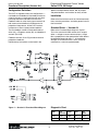
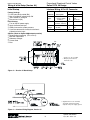
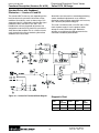
Functional Description (Version AJ)
Options and Adjustments section. Not all jumpers
and potentiometers are functional on every version.
Configuration Definition
The D1FX is supplied in two basic configurations —
non-feedback and feedback. Non-feedback refers to
valves having only a command input with any feedback loop closures made external to the valve.
Feedback refers to valves having input terminals for
both command and feedback and electronics for
proportional loop closure. All the D1FX versions
incorporate an internal spool position feedback.
Installation
Refer to the back of the manual for fluid recommendations, mounting restrictions, and other general installation instructions.
Standard Driver — Version AJ
The non-feedback versions include the Standard
driver (AJ), a European version (BJ), and deadband
versions (DJ & DK).
Detailed setup instructions can be found in the
Refer to the Functional Block diagram in figure 1.
This is the standard 24 VDC version which accepts
either a voltage or current command input. Output
flow is proportional to the spool position which follows
the Adjusted Command signal. ± 10 V reference
voltages are available on Pins A and F of the I/O
connector for a command potentiometer.
Figure 1 — Version AJ Functional Block Diagram
Diagnostic Chart
Feedback versions (CJ & CK) provide for external
proportional feedback.
2
CMD
TP2
Adj Cmd
FLOW
LED
TP1
Spool
+10V
+10V
PÔB
Grn
+10V
-10V
-10V
PÔA
Red
-10V
Parker Hannifin Corporation
Hydraulic Valve Division
Elyria, Ohio 44035 USA
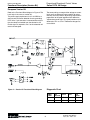
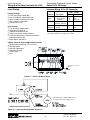
Wiring & Initial Setup (Version AJ)
Proportional Directional Control Valves
Series D1FX, 30 Design
Initial Startup
Interface Wiring, 6 Pin I/O Connector
Bulletin 2583-M1/USA
EHC** 8 Cable
Factory Settings:
LVDT hydraulically nulled (R3)
Max A and Max B adjusted fully CW
JP3 inserted: X1 Cmd gain
Bias set for 0 V (R1)
Initial Startup:
Turn on the DC power supply.
Apply the Command input
Slowly increase the system pressure
Cycle the command and verify that the flow is
proportional to the input.
Options: (Refer to Options/Adjustments section)
Spool position monitoring (TP1 or Pin C)
Max flow adjustments
Reference voltages
Current Cmd
Bias
•
•
•
•
Function
•
•
•
•
•
•
•
•
•
Description
Pin
Wire Color
Power
Supply
24VDC Nom.
+ Power Supply
Common
E
D
Red
Grn & Yel
Command
±10 VDC signal
4-20 mA, ±20 mA
B
Blue
Reference
Voltages
+10 VDC
-10 VDC
A
F
Orn
Wht
Spool
±10 VDC
C
Blk
**
* Factory set – Do not adjust
** Min pots present but not
functional on AJ
Figure 2 — Version AJ Board Setup
** Signal Common for an externally
generated command should be
separate from power supply ground.
Figure 3 — Interface Wiring Diagram, Version AJ
3
Parker Hannifin Corporation
Hydraulic Valve Division
Elyria, Ohio 44035 USA
Proportional Directional Control Valves
Series D1FX, 30 Design
Bulletin 2583-M1/USA
Functional Description (Version BJ)
European Version BJ
The command input accepts either voltage or current
inputs and has differential input capability for noise
immunity and easy reversal of phasing. Output flow is
proportional to the spool position which follows the
adjusted command signal. The spool position may be
observed at TP1 or at Pin F. Reference voltages are
not available.
Refer to the Functional Block diagram in Figure 4. The
basic logic is the same as version AJ.
The power supply requirement is still +24 VDC but a
separate wire has been added for chassis grounding.
Pin E of the 7 pin connector is connected internally to
the valve body but isolated from the electronics. An
Enable signal is required at Pin C or the solenoids will
remain de-energized.
Figure 4 — Version BJ Functional Block Diagram
Diagnostic Chart
4
-CMD/
+CMD
TP2
Adj Cmd
FLOW
LED
TP1
Spool
+/-10V
+10V
PÔB
Grn
+10V
-/+10V
-10V
PÔA
Red
-10V
Parker Hannifin Corporation
Hydraulic Valve Division
Elyria, Ohio 44035 USA
Wiring & Initial Setup (Version BJ)
Proportional Directional Control Valves
Series D1FX, 30 Design
Initial Startup
Interface Wiring, 7 Pin I/O Connector
Bulletin 2583-M1/USA
EHC** 8G Cable
Factory Settings:
LVDT hydraulically nulled (R3)
Max A and Max B adjusted fully CW
Min A and Min B adjusted fully CCW
JP3 inserted: X1 Cmd gain
Bias set for 0 V (R1)
Function
•
•
•
•
•
Initial Startup:
Turn on the DC power supply
Adjust Min A and Min B
Apply the command input
Slowly increase the system pressure
Cycle the command and verify that the flow is
proportional to the input
Adjust Max A and Max B
•
•
•
•
•
•
Description
Pin
Wire Color
Power
Supply
24VDC Nom.
+ Power Suply
Common
A
B
Red
Blk
Enable
5 to 30 VDC
C
Yel
Command
±10 VDC signal
4-20 mA, ±20mA
+CMD
-CMD
D
E
Blue
Orn
Spool
±10 VDC
F
Wht
Chassis
Ground
To valve body
G
Grn
Options: (Refer to Options/Adjustments section)
•
•
•
•
•
Spool position monitoring (TP1 or Pin F)
Min adjustments
Max flow adjustments
Current Cmd
Bias
* Factory set – Do not adjust
Figure 5 — Version BJ Board Setup
Both terminals
must be connected
Figure 6 — Interface Wiring Diagram, Version BJ
5
Parker Hannifin Corporation
Hydraulic Valve Division
Elyria, Ohio 44035 USA
Proportional Directional Control Valves
Series D1FX, 30 Design
Bulletin 2583-M1/USA
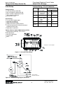
Functional Description (Versions CJ & CK)
External Closed Loop Feedback —
Versions CJ and CK
Special Note: The successful design and startup of
either a closed loop positioning or velocity control
system requires considerable forethought and a good
understanding of the dynamics of the system and the
load one is attempting to control. Closed loop feedback control is a broad topic and far exceeds the
scope of this instruction set. It is the intention of the
following instruction sheet to provide the necessary
information to set-up the D1FX for use in typical
closed loop applications. It is the responsibility of the
user to understand the limitations, hazards, and
implications of closed loop feedback control systems,
as well as detailed tuning procedures required
by some control schemes.
The feedback version is available in both a 24 VDC
and 12 VDC nominal power supply. It has the option of
either a voltage or current command signal. The
feedback signal must be a voltage signal and can not
exceed ±10 VDC (±5 VDC for CK). The feedback
signal may have the same or opposite polarity to the
command signal but must be the same magnitude as
the command signal as there are no scaling adjustments provided. Reference voltages are available on
pins A & F of the I/O connector for the command or
feedback potentiometer.
Figure 7 — Version CJ Functional Block Diagram
Diagnostic Chart
The outer loop has proportional feedback. There are
adjustable gains for both flow directions. Minimum
threshold adjustments are available to optimally tune
closed loop positioning systems.
INPUTS
6
TP2
Error
FLOW
LED
TP1
Spool
CMD>FDBK
-V
PÔA
Red
-V
CMD<FDBK
+V
PÔB
Grn
+V
Parker Hannifin Corporation
Hydraulic Valve Division
Elyria, Ohio 44035 USA
Wiring & Initial Setup (Versions CJ & CK)
Proportional Directional Control Valves
Series D1FX, 30 Design
Initial Startup
Interface Wiring, 6 Pin I/O Connector
Bulletin 2583-M1/USA
EHC** 8 Cable
Factory Settings:
•
•
•
•
•
•
Function
LVDT hydraulically nulled (R3)
Max A and Max B adjusted approx half way
Min A and Min B adjusted fully CCW
JP3 inserted-proportional gain
JP4 inserted-(Invert Fdbk)
Bias set for 0 V (R1)
•
•
•
Pin
24VDC Nom.
+Power Supply
Common
E
D
Red
Grn & Yel
*Command ±10 VDC signal
0 to 20 mA
B
Blue
Reference
Voltages
+10 VDC
-10 VDC
A
F
Orn
Wht
*FDBK
±10 VDC
C
Blk
*Power
Supply
Initial Startup:
•
•
•
•
Description
Turn on the DC power supply
Adjust Min A and Min B
Connect the command input
Connect the feedback input (Insert JP4 if the Fdbk
and Cmd have the same polarity. Remove JP4 and
insert JP5 for opposite polarity.)
Slowly increase the system pressure
Cycle the command and verify that the Fdbk
follows the Cmd
Adjust Max A and Max B
Wire Color
* “CK” version requires 12 VDC power supply and ±5 VDC
input signals. Reference voltages are ±5 VDC.
Options: (Refer to Options/Adjustments section)
•
•
•
•
•
•
Spool position monitoring (TP1)
Min adjustments
Max gain adjustments
Reference voltages
Current Cmd
Bias
Figure 8 — Version CJ Board Setup
* Factory set – Do not adjust
** Signal Common for CMD or FDBK
should be separate from power supply
ground.
Figure 9 — Interface Wiring Diagram, Version CJ
7
Parker Hannifin Corporation
Hydraulic Valve Division
Elyria, Ohio 44035 USA
Proportional Directional Control Valves
Series D1FX, 30 Design
Bulletin 2583-M1/USA
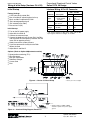
Functional Description (Versions DJ & DK)
Standard Driver with Deadband
Eliminators — Versions DJ and DK
The standard D1FX valve may not, depending on the
load, be electrically symmetrical about the no-flow
condition. Occasionally, (such as when using a PLC
generated signal) it is desirable to equalize the signal
needed for similar flow from P to A and P to B.
Deadband or minimum threshold adjustments are
designed to make the D1FX electrically symmetrical
about the no-flow condition.This is a means of more
easily hydraulically nulling and reducing the no-flow
deadband at the same time.
Should this valve be used in a closed loop positioning
system, deadband adjustments are an effective
method of achieving higher repeatability and accuracy
with a relatively low position loop gain.
Figure 10 — Version DJ Functional Block Diagram
Diagnostic Chart
This valve is available in both a 24 VDC and 12 VDC
nominal power supply. It has the option of either
voltage or current command signal. Reference
voltages are available on the MS connector for the
command or feedback potentiometer.
CMD
8
TP2
Adj Cmd
FLOW
LED
TP1
Spool
+10V
-10V
PÔA
Red
-10V
-10V
+10V
PÔB
Grn
+10V
Parker Hannifin Corporation
Hydraulic Valve Division
Elyria, Ohio 44035 USA
Wiring & Initial Setup (Versions DJ & DK)
Proportional Directional Control Valves
Series D1FX, 30 Design
Initial Startup
Interface Wiring, 6 Pin I/O Connector
Bulletin 2583-M1/USA
EHC** 8 Cable
Factory Settings:
LVDT hydraulically nulled (R3)
Max A and Max B adjusted fully CW
Min A and Min B adjusted fully CCW
JP3 inserted: X 1 Cmd gain
Bias set for 0 V (R1)
Function
•
•
•
•
•
Description
Pin
24VDC Nom.
+Power Supply
Common
E
D
Red
Grn & Yel
*Command ±10 VDC signal
4-20 mA, ±20 mA
B
Blue
*Reference +10 VDC
Voltages
-10 VDC
A
F
Orn
Wht
*Spool
C
Blk
*Power
Supply
Initial Startup:
Turn on the DC power supply
Adjust Min A and Min B
Connect the command input
Slowly increase the system pressure
Cycle the command and verify that the flow is
proportional to the input
Adjust Max A and Max B
•
•
•
•
•
•
±10 VDC
Wire Color
* “DK” version requires 12 VDC power supply and ±5 VDC
input signal. Reference voltages are ±5 VDC.
Options: (Refer to Options/Adjustments section)
•
•
•
•
•
•
Spool position monitoring (TP1 or PIN C)
Min adjustments
Max flow adjustments
Reference voltages
Current Cmd
Bias
*Factory set – Do not
adjust
Figure 11 — Version DJ Board Setup
** Signal Common for CMD or FDBK should
be separate from power supply ground.
Figure 12 — Interface Wiring Diagram, Version DJ
9
Parker Hannifin Corporation
Hydraulic Valve Division
Elyria, Ohio 44035 USA
Options & Adjustments
Proportional Directional Control Valves
Series D1FX, 30 Design
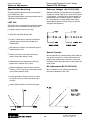
Spool Position Monitoring
Reference Voltages (AJ,CJ,CK,DJ,DK)
The spool position relative to its zero starting point
can be observed at TP1.
Reference voltages are available for wiring to potentiometers for Cmd or Fdbk inputs. Up to 10 mA current
is available but a 10 K ohm pot is recommended. The
potentiometer can be wired for either a ± voltage or
for a single polarity as shown below. Check wiring
before applying power. Incorrect wiring can result in
damage to the electronics.
Bulletin 2583-M1/USA
The spool voltage follows the command input after all
adjustments have been made.
LVDT Null
The D1FX valves are hydraulically nulled to a double
rod cylinder. The null should not need adjustment.
If it appears necessary to null the valve :
•
Adjust Min A and Min B fully CCW.
•
On the C version Max A and Max B should be
adjusted approx halfway with the fdbk input
disconnected.
•
With pressure at 500 psi, set command input to
approximately 0 volts.
•
Slowly increase the command until flow just
begins. Record this setting (+Cmd).
•
Slowly decrease the command until flow just
begins with a negative input (-Cmd).
•
Add the magnitude of the two values and then
divide by 2. This is the value at which flow should
start in either direction (Start).
•
If the magnitude of -Cmd was less than +Cmd,
set the input to -Start. Otherwise set the input
to +Start.
•
Slowly adjust R3 (NULL) until flow just begins.
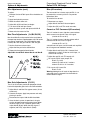
Manual Overrides
Manual overrides are a design feature which allow the
user to shift the valve in a system without electrical
power. In the center of each coil there is a brass pin.
Pushing on one of these pins with an allen wrench will
result in flow.
Min Adjustments (BJ,CJ,CK,DJ,DK)
Min A and Min B can be adjusted to reduce the
mechanical deadband in the valve.
10
Parker Hannifin Corporation
Hydraulic Valve Division
Elyria, Ohio 44035 USA
Options & Adjustments
Proportional Directional Control Valves
Series D1FX, 30 Design
Min Adjustments (cont.)
Bias (All versions)
To adjust:
Bulletin 2583-M1/USA
•
Remove Cmd and Fdbk inputs. Bias should be set
for 0 V.
The command bias is factory set to 0 VDC. It can
be used with a current input or PLC to provide
bidirectional flow.
•
•
•
•
•
•
Apply low hydraulic pressure
To reset the bias to zero:
Move the switch down to A
Turn back CCW until flow ceases
•
•
•
Move the switch up to B and repeat with Min B
Current or PLC Command (All versions)
Adjust Min A CW until flow just begins
Move switch to center for Run
Adjust Max A and Max B about midpoint.
Adjust bias (R1) until TP2 reads zero volts.
The 24 V versions have a 499 ohm current resistor
which converts 0 to 20 mA Ô 0 to 10 V signal.
(4 to 20 mA Ô 2 to 10 V)
Max Flow Adjustments (AJ,BJ,DJ,DK)
Max A and Max B can be used to limit or scale flow on
the open loop versions. Potentiometers fully CW results
in maximum spool travel. Fully CCW reduces spool
travel by 30% with JP3 gain and 10% with JP2 gain.
•
•
•
Disconnect any inputs.
The 12 V versions have a 249 ohm resistor which
converts 0 to 20 mA Ô 0 to 5 V signal.
(4 to 20 mA Ô 1 to 5 V)
Set the Cmd for maximum input
Adjust the Max pot for the desired flow
4-20 mA or 0-10V inputs can be biased and amplified
for full range on non-feedback versions.
Repeat for the opposite flow direction
•
Adjust Max A and B fully CW. Connect Cmd
required for “no flow” (5 volts for 0-10V input, 12
mA for 4-20 mA input)
•
•
Adjust bias pot R1 until TP2 equals 0 V.
Adjust Min A and Min B before Max A and Max B.
For a gain of X2.5 insert jumper JP2
0-10 V Ô ±12.5V
4-20 mA Ô ±10V on 24 V versions
4-20 mA Ô ±5V on 12 V versions
•
For a gain of X1 insert JP3
0-10 V Ô ±5V
Warning: Adding bias will result in flow when the
command signal is removed. Use the Enable to
remove the drive signal.
Max Gain Adjustments (CJ,CK)
The CJ & CK versions provide for proportional feedback with adjustable gains for the A and B solenoids.
•
Adjust Max A and Max B to approx center (15 out
of 30 turns).
•
Connect the inputs. Apply low pressure and verify
phasing is correct.
•
•
Disconnect the inputs. Add the Min thresholds.
Once the basic system is operational, the gain
can be adjusted for optimum performance. When
the error signal at TP2 is positive (green LED),
adjust Max B (R101). When the error signal is
negative (red LED), adjust Max A (R102).
11
Parker Hannifin Corporation
Hydraulic Valve Division
Elyria, Ohio 44035 USA
Proportional Directional Control Valves
Series D1FX, 30 Design
Bulletin 2583-M1/USA
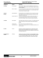
Trouble-Shooting
Symptom
Cause
Solution
Instability
Power supply?
Select a power supply not current limited below 4.0 Amps. Use a
separate power supply for each valve. The power supply should be
chassis grounded.
Noise on inputs?
To verify, disconnect input signals to D1FX. Jumper Cmd and Fdbk
terminals to common. For best results use a separate ground wire
for signal inputs and power supply.
Min adjustments?
Min adjustments can be adjusted such that the spool cannot stop
flow and there will be no stable operating point. Remove the Min
adjustments and start over.
System variations?
The valve was hydraulically nulled for a double rod cylinder. In a
closed loop system drift may occur with no inputs connected.
Connect the feedback and make external loop gain adjustment.
Flow limited?
Adjust Max CW for more flow on versions A, B, and D. Correct gain
jumper inserted (JP2 or JP3)? Verify that the command input is
correct.
Floating input?
Both inputs must be connected on B versions.
System pressure?
Verify that the system pressure is set as required and there are no
other flow paths.
No Flow
Power?
Verify there is power to the board and it is wired with the correct
polarity. Verify that the ENABLE signal is present on Version B.
Verify that the connections to the valve subplate are correct. Verify
the hydraulic pump is on.
No Proportional
Control
Phasing?
If Version A, B, or D is connected to an external feedback system,
verify open loop operation of valve with a potentiometer. If Version
C, make sure proper feedback jumper (JP4 or JP5) is installed.
Improper system phasing would result in maximum flow output.
Actuator
Drifting
Low Flow
12
Parker Hannifin Corporation
Hydraulic Valve Division
Elyria, Ohio 44035 USA
Proportional Directional Control Valves
Series D1FX, 30 Design
Bulletin 2583-M1/USA
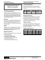
Installation Information
Torque Specifications
FOR MAXIMUM VALVE RELIABILITY,
ADHERE TO THE FOLLOWING
INSTALLATION INFORMATION
The recommended torque values are for the bolts
which mount the valve to the manifold or subplate are
as follows:
NFPA
Size
Fluid Recommendations
D03
Premium quality mineral based hydraulic oil with a
viscosity range between 150-250 SSU (32-54 cst.) at
38°C (100°F) is recommended. The absolute operation viscosity range is from 75-600 SSU (15-130 cst.).
Oil should have maximum anti-wear properties and
rust and oxidation treatment.
Bolt Thread Size
Metric
English
M5 x 0.8
10-24 UNC
Torque
5.6 N.m.
(50 in.-lbs.)
Mounting Restriction
In order to ensure proper operation, the D1FX must
be mounted horizontally. If the valve is mounted
vertically, a check valve with a minimum rating of
1.4 Bar (20 PSI) should be placed in the tank line to
maintain back pressure to the valve.
Filtration
For maximum valve and system component life, the
system should be protected from contamination at a
level not to exceed 125 particles greater than 10
microns per milliliter of fluid. (SAE Class 4 or better /
ISO Code 16/13).
Tank Line Surges
If several valves are piped with a common tank line,
flow surges in the line may cause an unexpected
spool shift. Separate tank lines should be used when
line surges are expected.
Silting
Silting can cause any sliding spool valve to stick, and
not spring return, if held shifted under pressure for
long periods of time. The valve should be cycled
periodically to prevent sticking.
Subplate Specifications
Subplate
SPD23
SPD2330
SPD23S
SPD23SA
Special Installations
Consult your Parker representative for any application
requiring the following :
Pressure above rated.
Fluid other than those specified.
Synthetic or fire-resistant fluids.
Oil temperature above 71.1°C (160°F).
Flow path other than normal.
Non-standard power supply grounding.
Port Size
3/8" NPTF
3/8" NPTF
9/16-18 NPTF
9/16-18 NPTF
Location
Bottom
Bottom
Bottom
Side
Max. Pressure
PSI
Bar
3,000
210
5,000
345
3,000
210
3,000
210
•
•
•
•
•
•
13
Parker Hannifin Corporation
Hydraulic Valve Division
Elyria, Ohio 44035 USA
Proportional Directional Control Valves
Series D1FX, 30 Design
Bulletin 2583-M1/USA
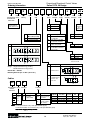
Ordering Information
D1F
X
D03
Control
Electrohydraulic Option
Directional Flow
Control Valve
0
0
30
Electronics
Accessory
Valve
Accessory
Design
Series
E
Equal
Metering
Spool
Flow
Code
Style
Integral LVDT &
Control Electronics
Seal
Option
Electronic
Variations
Code
Description
N
V
Code
Nominal Flow @
∆P=10 Bar (145 PSI)
C
F
7.5 LPM (2.0 GPM)
15 LPM (4.0 GPM)
Code
A
B
C
Code
Spool
D
Power
Supply
Not
Required
For
Ordering
Nitrile
Viton
Description
Standard Driver
w/ 6 pin MS
Euro Driver (7 pin MS)
w/ external shutdown
External Close Loop Pos.
Driver w/ 6 pin MS
Standard Driver
w/ deadband eliminator
& 6 pin MS
Code
Description
0
Standard
Code
Description
0
Standard
Code
Description
01
J
*K
02
24 VDC
12 VDC
* Only available in
versions C & D
Code
Description
C
Bi-Directional
K
Uni-Directional
Flow P ➔ A
&B➔T
Symbol
Weight: Single Solenoid 3.2 kg (7.0 lbs.);
Double Solenoid 3.4 kg (7.5 lbs.)
Bolt Kit No. — BK209
Mounting Bolt Torque: 5.6 N.m. (50 in.-lbs.)
Cables
8
EHC
Electrohydraulic Length Cable Type
Cable for
D1FX Valve
Code
3
6
9
12
15
Length
Length
in
Connector
Type
Code
Description
8
8-wire, 18 awg.
shielded
(Alpha 5388)
Code
Description
Omit
Standard
Connector 6 Pin
for D1FX
G
7 Pin Connector
for Euro, D1FX
“B” variation
Feet
Subplate
Port Size
Location
SPD23
3/8" NPTF
Bottom
SPD2330
3/8" NPTF
Bottom
SPD23S 9/16-18 NPTF Bottom
SPD23SA 9/16-18 NPTF
Side
Max. Pressure
PSI
Bar
3,000
210
5,000
345
3,000
210
3,000
210
Note: For D1FX connector only, order part #697561 (6-pin)
For D1FX, Variation “B” connector only, order part #697323 (7-pin)
Use Power Supply #PS24, 24 VDC
14
Parker Hannifin Corporation
Hydraulic Valve Division
Elyria, Ohio 44035 USA
Proportional Directional Control Valves
Series D1FX, 30 Design
Bulletin 2583-M1/USA
Offer of Sale
The items described in this document and other documents or descriptions provided by Parker Hannifin Corporation, its subsidiaries and its
authorized distributors are hereby offered for sale at prices to be established by Parker Hannifin Corporation, its subsidiaries and its authorized
distributors. This offer and its acceptance by any customer ("Buyer") shall be governed by all of the following Terms and Conditions. Buyer’s order
for any such items, when communicated to Parker Hannifin Corporation, its subsidiary or an authorized distributor ("Seller") verbally or in writing,
shall constitute acceptance of this offer.
Seller shall have the right to alter, discard or otherwise dispose of any
1. Terms and Conditions of Sale: All descriptions, quotations,
special tooling or other property in its sole discretion at any time.
proposals, offers, acknowledgments, acceptances and sales of Seller’s
8. Buyer’s Property: Any designs, tools, patterns, materials, drawproducts are subject to and shall be governed exclusively by the terms
ings, confidential information or equipment furnished by Buyer or any
and conditions stated herein. Buyer’s acceptance of any offer to sell is
other items which become Buyer’s property, may be considered
limited to these terms and conditions. Any terms or conditions in
obsolete and may be destroyed by Seller after two (2) consecutive
addition to, or inconsistent with those stated herein, proposed by Buyer
years have elapsed without Buyer placing an order for the items which
in any acceptance of an offer by Seller, are hereby objected to. No such
are manufactured using such property, Seller shall not be responsible
additional, different or inconsistent terms and conditions shall become
for any loss or damage to such property while it is in Seller’s possession
part of the contract between Buyer and Seller unless expressly
or control.
accepted in writing by Seller. Seller’s acceptance of any offer to
9. Taxes: Unless otherwise indicated on the face hereof, all prices and
purchase by Buyer is expressly conditional upon Buyer’s assent to all
charges are exclusive of excise, sales, use, property, occupational or
the terms and conditions stated herein, including any terms in addition
like taxes which may be imposed by any taxing authority upon the
to, or inconsistent with those contained in Buyer’s offer, Acceptance of
manufacture, sale or delivery of the items sold hereunder. If any such
Seller’s products shall in all events constitute such assent.
taxes must be paid by Seller or if Seller is liable for the collection of such
2. Payment: Payment shall be made by Buyer net 30 days from the
tax, the amount thereof shall be in addition to the amounts for the items
date of delivery of the items purchased hereunder. Amounts not timely
sold. Buyer agrees to pay all such taxes or to reimburse Seller therefore
paid shall bear interest at the maximum rate permitted by law for each
upon receipt of its invoice. If Buyer claims exemption from any sales,
month or portion thereof that the Buyer is late in making payment. Any
use or other tax imposed by any taxing authority, Buyer shall save
claims by Buyer for omissions or shortages in a shipment shall be
Seller harmless from and against any such tax, together with any
waived unless Seller receives notice thereof within 30 days after
interest or penalties thereon which may be assessed if the items are
Buyer’s receipt of the shipment.
held to be taxable.
3. Delivery: Unless otherwise provided on the face hereof, delivery
10. Indemnity For Infringement of Intellectual Property Rights:
shall be made F.O.B. Seller’s plant. Regardless of the method of
Seller shall have no liability for infringement of any patents, trademarks,
delivery, however, risk of loss shall pass to Buyer upon Seller’s
copyrights, trade dress, trade secrets or similar rights except as
delivery to a carrier. Any delivery dates shown are approximate only
provided in this Part 10. Seller will defend and indemnify Buyer against
and Seller shall have no liability for any delays in delivery.
allegations of infringement of U.S. Patents, U.S. Trademarks, copy4. Warranty: Seller warrants that the items sold hereunder shall be
rights, trade dress and trade secrets (hereinafter ‘Intellectual Property
free from defects in material or workmanship for a period of 18 months
Rights’). Seller will defend at its expense and will pay the cost of any
from date of shipment from Parker Hannifin Corporation. THIS WARsettlement or damages awarded in an action brought against Buyer
RANTY COMPRISES THE SOLE AND ENTIRE WARRANTY PERbased on an allegation that an item sold pursuant to this contract
TAINING TO ITEMS PROVIDED HEREUNDER. SELLER MAKES
infringes the Intellectual Property Rights of a third party. Seller’s
NO OTHER WARRANTY, GUARANTEE, OR REPRESENTATION
obligation to defend and indemnify Buyer is contingent on Buyer
OF ANY KIND WHATSOEVER. ALL OTHER WARRANTIES, INnotifying Seller within ten (10) days after Buyer becomes aware of such
CLUDING BUT NOT LIMITED TO, MERCHANTABILITY AND FITallegations of infringement, and Seller having sole control over the
NESS FOR PURPOSE, WHETHER EXPRESS, IMPLIED, OR ARISdefense of any allegations or actions including all negotiations for
ING BY OPERATION OF LAW, TRADE USAGE, OR COURSE OF
settlement or compromise. If an item sold hereunder is subject to a
DEALING ARE HEREBY DISCLAIMED.
claim that it infringes the Intellectual Property Rights of a third party,
NOTWITHSTANDING THE FOREGOING, THERE ARE NO
Seller may, at its sole expense and option, procure for Buyer the right
WARRANTIES WHATSOEVER ON ITEMS BUILT OR ACQUIRED
to continue using said item, replace or modify said item so as to make
WHOLLY OR PARTIALLY, TO BUYER’S DESIGNS OR SPECIFIit noninfringing, or offer to accept return of said item and return the
CATIONS.
purchase price less a reasonable allowance for depreciation. Notwith5. Limitation Of Remedy: SELLER’S LIABILITY ARISING FROM
standing the foregoing, Seller shall have no liability for claims of
OR IN ANY WAY CONNECTED WITH THE ITEMS SOLD OR THIS
infringement based on information provided by Buyer, or directed to
CONTRACT SHALL BE LIMITED EXCLUSIVELY TO REPAIR OR
items delivered hereunder for which the designs are specified in whole
REPLACEMENT OF THE ITEMS SOLD OR REFUND OF THE
or part by Buyer, or infringements resulting from the modification,
PURCHASE PRICE PAID BY BUYER, AT SELLER’S SOLE OPcombination or use in a system of any item sold hereunder. The
TION. IN NO EVENT SHALL SELLER BE LIABLE FOR ANY INCIforegoing provisions of this Part 10 shall constitute Seller’s sole and
DENTAL, CONSEQUENTIAL OR SPECIAL DAMAGES OF ANY
exclusive liability and Buyer’s sole and exclusive remedy for infringeKIND OR NATURE WHATSOEVER, INC.
ment of Intellectual Property Rights.
LUDING BUT NOT LIMITED TO LOST PROFITS ARISING FROM OR
If a claim is based on information provided by Buyer or if the design for
IN ANY WAY CONNECTED WITH THIS AGREEMENT OR ITEMS
an item delivered hereunder is specified in whole or in part by Buyer,
SOLD HEREUNDER, WHETHER ALLEGED TO ARISE FROM
Buyer shall defend and indemnify Seller for all costs, expenses or
BREACH OF CONTRACT, EXPRESS OR IMPLIED WARRANTY,
judgments resulting from any claim that such item infringes any patent,
OR IN TORT, INCLUDING WITHOUT LIMITATION, NEGLIGENCE,
trademark, copyright, trade dress, trade secret or any similar right.
FAILURE TO WARN OR STRICT LIABILITY.
11. Force Majeure: Seller does not assume the risk of and shall not be
6. Changes, Reschedules and Cancellations: Buyer may request to
liable for delay or failure to perform any of Seller’s obligations by reason
modify the designs or specifications for the items sold hereunder as
of circumstances beyond the reasonable control of Seller (hereinafter
well as the quantities and delivery dates thereof, or may request to
‘Events of Force Majeure’). Events of Force Majeure shall include
cancel all or part of this order, however, no such requested modificawithout limitation, accidents, acts of God, strikes or labor disputes, acts,
tion or cancellation shall become part of the contract between Buyer
laws, rules or regulations of any government or government agency,
and Seller unless accepted by Seller in a written amendment to this
fires, floods, delays or failures in delivery of carriers or suppliers,
Agreement. Acceptance of any such requested modification or cancelshortages of materials and any other cause beyond Seller’s control.
lation shall be at Seller’s discretion, and shall be upon such terms and
12. Entire Agreement/Governing Law: The terms and conditions set
conditions as Seller may require.
forth herein, together with any amendments, modifications and any
7. Special Tooling: A tooling charge may be imposed for any special
different terms or conditions expressly accepted by Seller in writing,
tooling, including without limitation, dies, fixtures, molds and patterns,
shall constitute the entire Agreement concerning the items sold, and
acquired to manufacture items sold pursuant to this contract. Such
there are no oral or other representations or agreements which pertain
special tooling shall be and remain Seller’s property notwithstanding
thereto. This Agreement shall be governed in all respects by the law of
payment of any charges by Buyer. In no event will Buyer acquire any
the State of Ohio. No actions arising out of the sale of the items sold
interest in apparatus belonging to Seller which is utilized in the
hereunder or this Agreement may be brought by either party more than
notwithstanding any charges paid by Buyer. Unless otherwise agreed,
two (2) years after the cause of action accrues.
15
Parker Hannifin Corporation
Hydraulic Valve Division
Elyria, Ohio 44035 USA
9/91-P
Proportional Directional Control Valves
Series D1FX, 30 Design
Bulletin 2583-M1/USA
Parker Hannifin Corporation
Hydraulic Valve Division
520 Ternes Avenue
Elyria, Ohio 44035 USA
Tel: (216) 366-5200
Fax: (216) 366-5253
Printed on recycled paper,
using soy inks.
12/95, 5M, PHD, Printed in the USA
16
Parker Hannifin Corporation
Hydraulic Valve Division
Elyria, Ohio 44035 USA