1
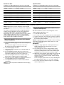
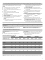
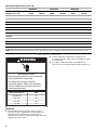
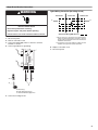
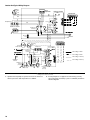
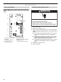
HEAT PUMP INSTALLATION INSTRUCTIONS
Table of Contents
HEAT PUMP SAFETY.....................................................................1
INSTALLATION REQUIREMENTS ................................................1
Tools and Parts ............................................................................2
System Requirements..................................................................2
Location Requirements ................................................................2
Electrical Requirements ...............................................................3
INSTALLATION INSTRUCTIONS ..................................................4
Inspect Shipment .........................................................................4
Connect Refrigerant Lines ...........................................................4
Charge Refrigerant Lines .............................................................5
Make Electrical Connections .......................................................8
Complete Installation..................................................................10
SEQUENCE OF OPERATION ......................................................11
Cooling Cycle .............................................................................11
Heating Cycle .............................................................................11
Defrost Cycle..............................................................................11
Adjust Defrost System ...............................................................12
Troubleshoot the Defrost System ..............................................13
SYSTEM MAINTENANCE ............................................................13
ASSISTANCE OR SERVICE .........................................................13
Accessories ................................................................................13
WARRANTY ..................................................................................14
HEAT PUMP SAFETY
Your safety and the safety of others are very important.
We have provided many important safety messages in this manual and on your appliance. Always read and obey all safety
messages.
This is the safety alert symbol.
This symbol alerts you to potential hazards that can kill or hurt you and others.
All safety messages will follow the safety alert symbol and either the word “DANGER” or “WARNING.”
These words mean:
DANGER
WARNING
You can be killed or seriously injured if you don't immediately
follow instructions.
You can be killed or seriously injured if you don't follow
instructions.
All safety messages will tell you what the potential hazard is, tell you how to reduce the chance of injury, and tell you what can
happen if the instructions are not followed.
INSTALLATION REQUIREMENTS
These instructions are intended as a general guide only for use by
qualified persons and do not supersede any national or local
codes in any way. The installation must comply with all state and
local codes as well as the National Electrical Code.
Whirlpool Gold® Models W2GH3
48632A008
■
■
The heat pump is designed and approved for outdoor use
only.
The heat pump must be installed with no ductwork in the
airstream. The outdoor fan is not designed to operate against
any additional static pressure.
Tools and Parts
Gather the required tools and parts before starting installation.
Read and follow the instructions provided with any tools listed
here.
Tools Needed
■
■
Torch
¹⁄₄" (6.4 mm) nut driver
■
Parts Needed
Check local codes and HVAC supplier. Check existing electrical
supply, and read “Electrical Requirements,” “Location
Requirements,” “System Requirements” and “Connect
Refrigerant Lines.”
⁵⁄₁₆" (7.6 mm) nut driver
System Requirements
Heat pump system matches are derived from actual laboratory
testing of matched systems. It is recommended that only
matching equipment be used to ensure proper operation and
efficient performance.
■ The designed system matches are listed in the heat pump
specification sheets and on the heat pump refrigerant
charging instructions located on the back of the service
access panel.
■ Refrigerant charging instructions include a list of matching
indoor equipment with the proper thermal expansion valve
size and amount of refrigerant charge required.
■ This heat pump has been factory charged with a quantity of
refrigerant (R-22) sufficient for a matched indoor coil and a
maximum 15 ft (4.6 m) of refrigerant line.
Indoor System Thermal Expansion Valve
■
■
■
Check the indoor coil thermal expansion valve to see whether
it matches the required thermal expansion valve for the
indoor coil and heat pump combination being installed.
Refer to the refrigerant charge label located on the inside of
the heat pump access panel for the correct thermal
expansion valve size required.
Replace the thermal expansion valve with the correct size if
this size is not already installed in the indoor coil. Instructions
for replacing the thermal expansion valve are provided with
the indoor coil.
Location Requirements
■
■
■
■
■
■
2
This heat pump is designed to be located outdoors with
sufficient clearance for free entrance to the inlet and
discharge air openings. The location must also allow for
adequate service access. See “Minimum Clearances.”
Where possible, select a location for the heat pump which is
shaded from the direct rays of the sun most of the time. North
or east locations are usually most desirable. Position the heat
pump to avoid direct contact with water, snow or ice from a
roofline overhead.
The heat pump must be installed on a solid, level mounting
pad that will not settle or shift. Isolate the pad from the
building structure to avoid possible transmission of sound or
vibration from the heat pump into the conditioned space.
The heat pump foundation should be raised to a minimum of
3" (7.6 cm) above finish grade. In areas which have prolonged
periods of temperatures below freezing, and/or snowfall, the
heat pump should be elevated above the average snow line.
If heat pump is to be installed on a flat roof, it should be on a
platform or other support which will raise the inlet air opening
12" (30.5 cm) minimum above the surface of the flat roof.
Avoid ice accumulation by ensuring free drainage of
condensate from defrost cycles. The heat pump should be
located away from walkways to avoid possible icing from
defrost condensate.
Avoid placing the heat pump near areas such as sleeping
quarters or study rooms. Normal operating sound levels may
be objectionable if the heat pump is placed near certain
rooms. A shift in sound type does occur during the defrost
mode. The defrost mode generally lasts no longer than
10 minutes.
Minimum Clearances
A B
48" (121.9 cm)
Overhead Clearance
(Discharge Air)
)
m )
c
5
ir
.
30 t A
" ( le
12 e (In
nc
ra
ea
Cl
C
E
D
F
G
H
Cl 36
ea "
ra (91
nc .4
e ( cm
Inl )
et
Ai
r)
ice
erv ce
S
)
n
cm ra
.2 lea
76 ss C
(
"
30 cce
A
A. Weatherproof disconnect switch
B. NEC class 1 wiring
C. NEC class 2 wiring
D. To power supply
12" (30.5 cm) Clearance
Between Unit and Building
E. House thermostat
F. To indoor unit
G. To indoor coil
H. Seal openings
Installing Vertical Runs (new construction shown)
Line Set Isolation
The following illustrations demonstrate procedures which ensure
proper refrigerant line set isolation.
This shows how to install line sets on vertical runs.
NOTE: Similar installation practices should be used if line set is
to be installed on exterior of outside wall.
IMPORTANT: Refrigerant lines must not contact structure.
Installing Horizontal Runs
B
This shows how to install line sets on horizontal runs.
NOTES:
■ To hang line set from joist or rafter, use either metal strapping
material or anchored heavy nylon wire ties.
■ Strap the vapor line to the floor joist or roof rafter at 8 ft
(2.4 m) intervals, then strap the liquid line to the vapor line.
A
C
C
D
H
E
F
G
H
E
D
G
A
8'
C
A
B
I
C
8'
J
D
E
L
E
G
D
K
H
A
C
A. Metal strapping material (around D. Metal strapping material (around
vapor line only)
vapor line only) and tape or heavy
nylon wire tie (around vapor and
B. Floor joist or roof rafter
liquid lines)
C. Tape or heavy nylon wire tie
E. Metal sleeve
Transition from Horizontal to Vertical
This shows how to make a transition from horizontal to vertical.
Style 1
Electrical Requirements
Style 2
A
WARNING
G
F
E
E. Anchored heavy nylon wire tie J. Caulk
A. Outside wall
K. Fiberglass
B. Space between wall F. Inside wall
insulation
and refrigerant line
G. Metal strapping material
L. PVC pipe
C. Vapor line wrapped H. Metal sleeve
in armaflex
I. Wood block between studs
D. Liquid line
D
B
B
C
C
Electrical Shock Hazard
Electrically ground condensing unit or heat pump.
F
E
D
A. Style 1—anchored heavy nylon wire tie
E. Metal sleeve
B. Tape or heavy nylon wire tie holding liquid F. Wall stud
line to vapor line.
G. Style 2—automotive
C. Liquid line
muffler-type hanger
D. Vapor line—wrapped in armaflex
Connect ground wire to ground lug.
Use copper wire for supply connection.
Correct wire gauge is shown in the chart below.
Failure to follow these instructions can result in
death or electrical shock.
Rating Plate Ampacity
AWG
Less than 15
14
16 - 20
12
21 - 30
10
31 - 50
8
NOTE: All outdoor wiring must be suitable for outdoor use. Use
copper conductors only.
3
■
All field wiring must be done in accordance with National
Electrical Code requirements, applicable requirements of UL,
or local codes, where applicable.
■
Electrical wiring, disconnect means and over-current
protection are to be supplied by the installer. Refer to the
rating plate for the maximum over-current protection,
minimum circuit ampacity, and operating voltage. See the
wiring diagrams in “Make Electrical Connections.”
INSTALLATION INSTRUCTIONS
Inspect Shipment
WARNING
Excessive Weight Hazard
Use two or more people to move and install
condensing unit or heat pump.
Failure to do so can result in back or other injury.
This heat pump is shipped in one package, completely
assembled and wired. The thermostat is shipped in a separate
carton when ordered.
1. Check the heat pump rating plate to confirm specifications
are as ordered.
2. Upon receipt of heat pump, inspect it for possible shipping
damage. Examine the heat pump inside the carton if the
carton is damaged.
If damage is found, it should be noted on the carrier’s freight bill.
Damage claims should be filed with the carrier immediately.
Claims of shortages should be filed with the seller within 5 days.
NOTE: If any damages are discovered and reported to the carrier,
do not install the heat pump because your claim may be denied.
Connect Refrigerant Lines
Refrigerant lines must be connected by a licensed, EPA certified
refrigerant technician in accordance with established procedures.
IMPORTANT:
■ Connecting refrigerant lines must be clean, dehydrated,
refrigerant-grade copper lines. Heat pumps should be
installed only with specified line sizes for approved system
combinations with elevation differences up to 15 ft (4.6 m)
and total length of up to 50 ft (15.2 m). See the Suction Line
Sizes and Liquid Line Sizes charts.
■ Sharp bends or possible kinking in the lines will cause a
reduction in performance.
■ To avoid contamination of the refrigerant system, do not
remove the caps from the lines or system connection points
until connections are ready to be completed.
1. Route the suction and liquid lines from the fittings on the
indoor coil to the fittings on the heat pump. Run the lines in
as direct a path as possible, avoiding unnecessary turns and
bends.
2. For product efficiency, be sure that the suction line is
insulated over the entire exposed length and that both
suction and liquid lines are not in direct contact with floors,
walls, ductwork, floor joists, or other piping.
3. Remove valve cores.
4. Wrap the service valves with a wet rag.
5. Connect the suction and liquid lines, using a brazing
compound. Braze with an alloy of silver or copper and
phosphorus with a melting point above 1,100°F (593ºC).
NOTE: Do not use soft solder.
4
6. Make sure indoor coil has been put in place according to the
Installation Instructions and is connected to the refrigerant
lines.
7. Replace valve cores.
8. Pressurize the lines and indoor coil with a pressure not to
exceed 20 psi.
9. Leak test the lines with a pressure not to exceed 20 psig.
10. Evacuate the indoor coil and lines to a minimum of
500 microns to remove contamination and moisture, then
disconnect the vacuum pump.
11. Open the suction and liquid service valves fully.
12. Insulate the suction line with refrigerant line insulation
material of ¹⁄₄" (6.4 mm) or more wall thickness.
13. Pack insulating material around refrigerant lines where they
penetrate the structure to protect the lines and to minimize
vibration transmission.
A
A. Insulating material around refrigerant lines
Suction Line Sizes
Liquid Line Sizes
Installations exceeding 100 ft (30.5 m) are not recommended.
Installations exceeding 100 ft (30.5 m) are not recommended.
Btu/h
Line Set Size—in. (cm) OD
Btu/h
Line Set Size—in. (cm) OD
18,000
³⁄₄ (1.9)
³⁄₄ (1.9)
³⁄₄ (1.9)
18,000
³⁄₈ (1)
³⁄₈ (1)
³⁄₈ (1)
24,000
³⁄₄ (1.9)
³⁄₄ (1.9)
³⁄₄ (1.9)
24,000
³⁄₈ (1)
³⁄₈ (1)
³⁄₈ (1)
30,000
³⁄₄ (1.9)
³⁄₄ (1.9)
³⁄₄ (1.9)
30,000
³⁄₈ (1)
³⁄₈ (1)
³⁄₈ (1)
36,000
⁷⁄₈ (2.2)
⁷⁄₈ (2.2)
⁷⁄₈ (2.2)
36,000
³⁄₈ (1)
³⁄₈ (1)
³⁄₈ (1)
42,000
⁷⁄₈ (2.2)
⁷⁄₈ (2.2)
⁷⁄₈ (2.2)
42,000
³⁄₈ (1)
³⁄₈ (1)
³⁄₈ (1)
48,000
⁷⁄₈ (2.2)
⁷⁄₈ (2.2)
⁷⁄₈ (2.2)
48,000
³⁄₈ (1)
³⁄₈ (1)
³⁄₈ (1)
60,000
1¹⁄₈ (2.9)
1¹⁄₈ (2.9)
1¹⁄₈ (2.9)
60,000
³⁄₈ (1)
³⁄₈ (1)
³⁄₈ (1)
Line Set
Length
Less than 25 ft 25 ft
(7.6 m)
(7.6 m)
Over 25 ft (7.6 m) and up
to 50 ft (15.2 m)
Line Set
Length
Less than 25 ft 25 ft
(7.6 m)
(7.6 m)
Over 25 ft (7.6 m) and up
to 50 ft (15.2 m)
Charge Refrigerant Lines
NOTE: Refrigerant lines must be charged by a licensed, EPA
certified refrigeration technician in accordance with established
procedures.
The outdoor condensing unit should be charged during warm
weather. However, applications arise in which charging must
occur in the colder months. The method of charging is
determined by the system’s refrigerant expansion device and the
outdoor ambient temperature. Choose one of the following
charge methods based on the system’s refrigerant expansion
device and the outdoor ambient temperature.
Measure the Liquid Line Temperature and the Outdoor
Ambient Temperature
1. Connect the manifold gauge set to the service valve ports as
follows:
■ Low pressure gauge to suction line service valve
■ High pressure gauge to liquid line service valve
2. Close manifold gauge set valves.
3. Connect the center manifold hose to an upright cylinder of
refrigerant (R-22).
4. If room temperature is below 70°F (21ºC), set the room
thermostat to call for heat. This will create the necessary load
for properly charging the system in the cooling cycle.
5. When the heating demand has been satisfied, switch the
thermostat to cooling mode with a set point of 68°F.
6. When pressures have stabilized, use a digital thermometer to
record the liquid and suction line temperatures.
7. Use a digital thermometer to record the outdoor ambient
temperature.
NOTE: The outdoor temperature will determine which charging
method to use.
Charge Using Weigh-In Method (Fixed Orifice/Thermal
Expansion Valve Systems)
Use this method if the system is void of refrigerant, or if the
outdoor ambient temperature is cool.
1. Locate and repair any leaks.
2. If necessary, recover the refrigerant from the condensing unit.
3. Conduct a leak check, then evacuate as previously outlined.
4. Weigh in the charge according to the total amount shown on
the condensing unit nameplate.
NOTE: If weighing facilities are not available or if the condensing
unit is being charged during warm weather, follow one of the
other charging methods.
IMPORTANT:
■ Refrigerant charge adjustment will be required for line set
lengths greater than 15 ft (4.6 m) and for non systemmatched evaporator coils.
■ The condensing unit is factory-charged with the proper
refrigerant charge amount for a matching evaporator and
15 ft (4.6 m) of refrigerant line. Refer to the condensing unit
rating plate for the exact amount of this factory charge.
■ Adjustment of the refrigerant charge will be necessary based
on the system combination and line length. To adjust the
refrigerant size for increased line lengths, add the following
amount of refrigerant.
For line set lengths greater than 15 ft (4.6 m), add refrigerant
by weighing in 0.60 oz per ft of ³⁄₈" (1 cm) O.D. liquid line.
■
If necessary, adjust the refrigerant charge for compatibility
with the evaporator coil.
5
Charge Using Sub-cooling Method (Fixed Orifice/Thermal Expansion Valve Systems)—Outdoor Temperatures 65°F
(18ºC) or Above
Use this method if charging a fixed orifice or Thermal Expansion
Valve system when the outdoor ambient temperature is 65°F
(18ºC) or above.
1. Attach the manifold gauge hose to the liquid service port.
2. If the condensing unit pressures are stable, use a digital
thermometer to record the liquid line temperature.
3. Record the liquid line pressure reading.
4. Use a temperature/pressure chart for refrigerant (R-22) to
determine the saturation temperature for the liquid line
pressure reading.
5. Subtract the liquid line temperature from the saturation
temperature to determine sub-cooling. See Sub-cooling
Values for Fixed Orifice or Thermal Expansion Valve Systems
chart.
_____ ° (Saturation Temperature °F) - _____ ° (Liquid Line
Temperature °F) = _____ ° (Sub-cooling Value °F)
6. Compare the sub-cooling value with those shown in Subcooling Values for Fixed Orifice or Thermal Expansion Valve
Systems chart.
■ If sub-cooling is greater than shown, recover some
refrigerant.
■ If sub-cooling is less than shown, add some refrigerant.
Sub-cooling Values for Fixed Orifice or Thermal Expansion Valve Systems
Outdoor
Liquid Sub-cooling—∆ºF
Temperature
W2GH318A
W2GH324A
ºF (ºC)
W2GH330A
W2GH336A
W2GH342A
W2GH348A
W2GH360A
65 (18)
13
15
14
13
13
15
14
75 (23.9)
10
13
12
10
10
13
12
85 (29.4)
8
11
11
8
8
11
11
95 (35)
7
9
10
7
7
9
10
105 (40.6)
6
8
9
6
6
8
9
115 (46.1)
3
5
6
3
3
5
6
Charge Using Superheat Method (Fixed Orifice Systems)—Outdoor Temperatures 65°F (18ºC) or Above
Use this method if charging a fixed orifice system when the
outdoor ambient temperature is 65ºF (18ºC) or above.
1. Attach the manifold gauge hose to the suction service port.
2. If the condensing unit pressures are stable, use a digital
thermometer to record the suction line temperature.
3. Record the suction line pressure reading.
4. Use a temperature/pressure chart for refrigerant (R-22) to
determine the saturation temperature for the suction line
pressure reading.
5. Subtract the saturation temperature from the suction line
temperature to determine the superheat. See Superheat
Values for Fixed Orifice Systems chart.
_____ ° (Suction Line Temperature °F) - _____ ° (Saturation
Temperature °F) = _____ ° (Superheat Value °F)
Superheat Values for Fixed Orifice Systems
6. Compare the superheat value with those shown in Superheat
Values for Fixed Orifice Systems chart.
■ If superheat is greater than shown, add some refrigerant.
■ If superheat is less than shown, recover some refrigerant.
6
(80° DB/67° WB Return Air)
Outdoor Ambient Temperature ºF (ºC)
Superheat ºF
60 (15.6)
38
65 (18.3)
35
70 (21.1)
30
75 (23.9)
26
80 (26.7)
22
85 (29.4)
18
90 (32.2)
12
95 (35)
8
100 (37.8)
5
105 (40.6)
0
Charge Using Approach Method (Thermal Expansion Valve Systems)—Outdoor Temperatures 65°F (18ºC) or Above
Use this method if charging a Thermal Expansion Valve system
when the outdoor ambient temperature is 65ºF (18ºC) or above.
NOTES:
■ The following procedure is intended as a general guide.
■ Use on Thermal Expansion Valve systems only.
■ For best results, indoor temperature should 70°F (21ºC) to
80°F (27ºC).
■ Monitor system pressures while charging.
1. Record outdoor ambient temperature using a digital
thermometer.
2. Attach high pressure gauge set.
3. Operate condensing unit for several minutes to allow system
pressures to stabilize.
4. Compare stabilized pressures with those provided in the
Normal Operating Pressures chart.
NOTES:
■
Significant differences could mean that the system is not
properly charged or that a problem exists with some
component in the system.
■ Pressures higher than those listed indicate that the
system is overcharged.
■ Pressures lower than those listed indicate that the system
is undercharged.
■ Verify adjusted charge using the approach method.
5. Use the same digital thermometer to check liquid line
temperature.
6. Subtract the outdoor ambient temperature from the liquid line
temperature to determine the approach temperature.
_____ ° (Liquid Line Temperature °F) - _____ ° (Outdoor
Ambient Temperature °F) = _____ ° (Approach
Temperature °F)
■
7. Compare the approach value with those shown in the
Approach Values for Thermal Expansion Valve Systems chart.
■ If the approach values are too high, add refrigerant to
lower the approach temperature
■ If the approach values are too low, recover refrigerant
from the system to increase the approach temperature.
Minor variations in these pressures may be expected due
to differences in installations.
Approach Values for Thermal Expansion Valve Systems
Model
W2GH318A
Temperature ºF 7
■
W2GH324A
W2GH330A
W2GH336A
W2GH342A
W2GH348A
W2GH360A
8
9
11
7
8
7
Approach value is the liquid line temperature minus the
outdoor ambient temperature (∆°F).
NOTE: For best results, use the same digital thermometer to
check both outdoor ambient and liquid temperatures.
Check Charge Using Normal Operating Pressures
Use the Normal Operating Pressures chart to perform
maintenance checks.
NOTES:
■ This chart is not a procedure for charging the system.
■
■
Minor variations in these pressures may be due to differences
in installations.
Significant deviations could mean that the system is not
properly charged or that a problem exists with some
component in the system.
Normal Operating Pressures (-18 to -36)
W2GH318A
Air Temperature Entering
Outdoor Coil ºF (ºC)
Liquid
W2GH324A
W2GH330A
W2GH336A
Suction
Liquid
Suction
Liquid
Suction
Liquid
Suction
Cooling
65 (18)
141
81
148
80
146
78
154
78
75 (23.9)
163
82
176
82
171
79
180
88
85 (29.4)
191
84
206
83
201
80
210
99
95 (35)
222
85
240
84
233
81
246
109
105 (40.6)
256
87
277
86
271
81
277
119
115 (46.1)
296
89
322
87
313
83
318
130
50 (10)
192
64
185
60
198
58
196
58
40 (4.4)
180
53
176
50
188
47
185
47
30 (1.1)
172
43
165
49
175
35
176
37
20 (-6.7)
164
34
162
31
163
26
170
30
Heating
NOTE: Values provided are typical pressures. Indoor unit match-up, indoor air quality and indoor load will cause pressures to vary.
7
Normal Operating Pressures (-42 to -60)
W2GH342A
Air Temperature Entering
Outdoor Coil ºF (ºC)
W2GH348A
W2GH360A
Liquid
Suction
Liquid
Suction
Liquid
Suction
65 (18)
139
67
147
78
146
67
75 (23.9)
163
74
173
79
170
74
85 (29.4)
191
81
203
80
199
81
95 (35)
220
84
236
81
230
84
105 (40.6)
256
85
273
83
266
85
115 (46.1)
294
87
315
84
306
87
50 (10)
204
59
212
59
214
60
40 (4.4)
195
49
195
40
202
50
30 (1.1)
184
39
189
39
191
40
20 (-6.7)
178
32
179
31
181
33
Cooling
Heating
NOTE: Values provided are typical pressures. Indoor unit match-up, indoor air quality and indoor load will cause pressures to vary.
Make Electrical Connections
■
WARNING
■
Electrical Shock Hazard
Electrically ground condensing unit or heat pump.
Connect ground wire to ground lug.
Use copper wire for supply connection.
Correct wire gauge is shown in the chart below.
Failure to follow these instructions can result in
death or electrical shock.
Rating Plate Ampacity
AWG
Less than 15
14
16 - 20
12
21 - 30
10
31 - 50
8
IMPORTANT:
■ Electrical wiring, disconnect means and over-current
protection are to be supplied by the installer. Refer to the
rating plate for the maximum over-current protection,
minimum circuit ampacity, and operating voltage. See wiring
diagrams later in this section.
8
Install an adequately sized branch circuit disconnect,
according to the NEC, within sight of and readily accessible
from heat pump.
The cable or conduit and fittings connected from the
disconnect to the heat pump shall be rated for outdoor use.
Single Phase Electrical Connections
WARNING
Typical Wiring Connection (low voltage circuit)
A
Electrical Shock Hazard
Disconnect power before servicing.
Thermostat
Indoor Unit
Outdoor Unit
R
C
Y
O
W
G
R
C
R
C
Y
O
W
W
G
B
Replace all parts and panels before operating.
Failure to do so can result in death or electrical shock.
1. Disconnect power.
2. Remove control box cover.
3. Connect the field supply wires L1 and L2 to contactor
terminals L1 and L2.
4. Connect ground wire to ground lug.
T2
T1
L2
L1
A
L2
24V Control Wiring (NEC Class 2)
A. Do not connect C (common) connection between
indoor unit and thermostat except when required
by the indoor thermostat. Refer to the thermostat
installation instructions.
B. C (common) connection between indoor unit and
outdoor unit required for proper operation.
6. Replace control box cover.
7. Reconnect power.
L1
B
C
A. Ground lug
B. Field supply ground wire
C. 208/230 volt field supply wires
5. Connect low voltage circuit.
9
Outdoor Unit Typical Wiring Diagram
Outdoor
Fan
Dual
Capacitor
Defrost Control
FAN
R
PR
BK
BK
BK
Thermostat
OR
Compressor
R
Y
S87
Low
Pressure Switch
(if used)
BK
COMMON
Crankcase Heater
(if used)
BK
Compressor
Contactor
High
Pressure Switch
(if used)
Ground
Lug
Ground
Thermostat
Reversing
Valve
Defrost
Thermostat
Defrost Control
Fan
Compressor
BK
Compressor
Contactor
R
Fan
Defrost
Control
Dual
Crankcase
Thermostat Capacitor
(if used)
PR
Low voltage - Field
Line voltage - Factory
Th
Y
Crankcase
Heater
(if used)
R
BK
Equipment
Ground
Line voltage - Field
Low
Pressure Switch
(if used)
er Def
m ro
os st
ta
t
OR
Reversing
Valve
BK
Low voltage - Factory
Compressor
Contactor
Coil
BK
Outdoor
Fan
High
Pressure
Switch
(if used)
Complete Installation
1. Operate the heat pump for a period of at least 15 minutes to
allow for pressures and temperatures to stabilize.
10
2. If heat pump does not appear to be functioning correctly,
have heat pump checked by a person certified by the EPA to
handle refrigerant.
SEQUENCE OF OPERATION
Cooling Cycle
Upon cooling demand, the thermostat closes circuit R to O and Y.
Closing R to O and Y energizes the reversing valve for cooling
operation and closes the heat pump contactor, starting the
compressor and outdoor fan. The thermostat automatically
closes R to G circuit, which also brings on the indoor fan at the
same time. Upon satisfying cooling demand, the thermostat will
open the above circuits and open the main contactor, stopping
the compressor and outdoor fan. If the indoor unit is equipped
with a delay timer, the blower will continue to operate for 60 to
90 seconds, which improves system efficiency.
Heating Cycle
Upon heating demand, the thermostat closes circuit R to Y, which
closes the heat pump contactor, starting the compressor and
outdoor fan. The reversing valve is not energized in the heating
mode. The thermostat again automatically brings on the indoor
fan at the same time. Upon satisfying heating demand, the
thermostat opens above circuits and stops heat pump operation.
Defrost Cycle
If the outdoor ambient conditions are such that frost forms on the
outdoor coil, the defrost control monitors the need for and
initiates and terminates defrost cycles as necessary to maintain
system performance.
The defrost control is time/temperature initiated and temperature
terminated with a maximum defrost time (time-out) of 10 minutes.
The time between defrost cycles is preset at 60-minute intervals
at the factory, but can be field adjusted between 30, 60, or
90 minutes. To adjust the time period between defrost cycles,
see “Adjust Time Between Defrost Cycles” in “Adjust Defrost
System.”
The defrost control will initiate a defrost cycle when the selected
time period has elapsed and the defrost sensor sees a
temperature below freezing. At the start of a defrost cycle, the
defrost control will energize the reversing valve solenoid, shifting
the reversing valve and de-energizing the outdoor fan. The
defrost relay will also close, energizing temporary heat for
increased comfort during defrost (if the indoor unit is so
equipped). The heat pump will remain in defrost until the defrost
sensor has determined that the frost has been removed from the
coil or a 10-minute period has elapsed, whichever comes first.
Defrost Thermostat
The defrost thermostat is located on the liquid line between the
check/expansion valve and the distributor. When defrost
thermostat senses 42ºF (5.6ºC) or cooler, the thermostat contacts
close and send a signal to the defrost control board to start the
defrost timing. It also terminates defrost when the liquid line
warms up to 70ºF (21.1ºC).
Defrost Control
The defrost control board includes the combined functions of the
time/temperature defrost control, defrost relay, diagnostic LEDs
and terminal strip for field wiring connections. See “Defrost
Control Board” illustration in “Adjust Defrost System.”
The defrost control provides automatic switching from normal
heating operation to defrost mode and back. During compressor
cycle (call for defrost), the defrost control accumulates
compressor run times at 30, 60 or 90 minute field-adjustable
intervals. If the defrost thermostat is closed when the selected
compressor run time interval ends, the defrost relay is energized
and defrost begins.
Defrost Control Timing Pins
Each timing pin selection provides a different accumulated
compressor run time period during one thermostat run cycle. This
time period must occur before a defrost cycle is initiated. The
defrost interval can be adjusted to 30 (T1), 60 (T2) or 90 (T3)
minutes. See “Defrost Control Board” illustration in “Adjust
Defrost System.” The defrost timing jumper is factory-installed to
provide a 60-minute defrost interval. If the timing selector jumper
is not in place, the defrost control defaults to a 90-minute defrost
interval. The maximum defrost period is 14 minutes and cannot
be adjusted.
A test option is provided for troubleshooting. The test mode may
be started any time the heat pump is in the heating mode and the
defrost thermostat is closed or jumpered. If the jumper is in the
test position at power-up, the defrost control will ignore the test
pins. When the jumper is placed across the Test pins for 2
seconds, the control will enter the defrost mode. If the jumper is
removed before an additional 5-second period has elapsed (7
seconds total), the heat pump will remain in defrost mode until
the defrost thermostat opens or 14 minutes have passed. If the
jumper is not removed until after the additional 5-second period
has elapsed, the defrost will terminate and the test option will not
function again until the jumper is removed and reapplied.
Pressure Switch Circuit
The defrost control incorporates a pressure switch circuit that
allows the application of an optional high pressure switch. See
“Defrost Control Board” illustration in “Adjust Defrost System.”
During a demand cycle, the defrost control will lock out the heat
pump if the optional high pressure switch opens. The diagnostic
LEDs will display a pattern for an open high pressure switch. See
“Diagnostic LEDs” in “Troubleshoot the Defrost System.” The
heat pump will remain locked out until the switch resets or is
reset.
Remove the factory-installed jumper before connecting the
optional high pressure switch to the control board.
NOTE: If you are not using a pressure switch, the factoryinstalled jumper wire must be connected.
11
Adjust Defrost System
Defrost Control Board
Adjust Time Between Defrost Cycles
Optional high pressure switch safety circuit connections
NOTE: To add the pressure switch, remove the factory-installed
jumper.
P1
FAN
30
60
90
A
WARNING
C2
TEST
K1 Relay
B
Electrical Shock Hazard
DS1
DS2
C
D
P5
U1
U2
O-OUT
Failure to do so can result in death or electrical shock.
P2
W1
L
C
24V
L
DF
F
I
R
C5
O
Y1-OUT
Y1
HI-PS K3 Relay
G
P6
TST PS DF C
A. Defrost interval timing pins
B. Test pins
C. Compressor delay pins
D. Reversing valve
E. Low pressure switch
12
R
Disconnect power before servicing.
Replace all parts and panels before operating.
K2 Relay
LO-PS
E
H
O Y1
F. Defrost thermostat
G. High pressure switch (optional)
H. Diagnostic LEDs
I. 24V terminal strip connections
1. Disconnect power.
2. Remove the control box cover.
3. Adjust the time period between defrost cycles by placing the
defrost time plug in the proper position. See “Defrost Control
Board.”
■ For 30-minute intervals between defrost cycles, move the
Defrost Time Setting Plug to the pins corresponding
to 30.
■ For 60-minute intervals between defrost cycles, move the
Defrost Time Setting Plug to the pins corresponding to
60 (this setting is the factory preset setting).
■ For 90-minute intervals between defrost cycles, move the
Defrost Time Setting Plug to the pins corresponding
to 90.
4. Replace the control box cover.
5. Reconnect power.
Troubleshoot the Defrost System
WARNING
Electrical Shock Hazard
Disconnect power before servicing.
Replace all parts and panels before operating.
Failure to do so can result in death or electrical shock.
Diagnostic LEDs
The defrost board uses 2 LEDs for diagnostics. The LEDs flash a
specific sequence according to the condition.
Defrost Control Board Diagnostic LEDs
Mode
Green LED
(DS2)
Red LED
(DS1)
No power to board
Off
Off
Normal operation/power to board
Simultaneous slow flash
Anti-short cycle lockout
Alternating slow flash
Low pressure switch fault
Off
Slow flash
Low pressure switch lockout
Off
On
High pressure switch fault
Slow flash
Off
High pressure switch lockout
On
Off
1.
2.
3.
4.
5.
6.
7.
8.
Disconnect power.
Remove control box cover.
Reconnect power and set thermostat for heating operation.
Observe LEDs and compare to Defrost Control Board
Diagnostic LEDs chart.
If a system failure is indicated, take appropriate action to
correct.
Turn off thermostat and disconnect power.
Replace control box cover.
Reconnect power.
SYSTEM MAINTENANCE
■
Leaves and other large obstructions should be removed from
the heat pump surfaces without damaging the fin surface of
the coil.
■
■
Routinely clean or change the indoor air filter. Should the
indoor coil become dirty, thus restricting airflow, call a
qualified service person to clean the coil surface.
An annual inspection by a qualified person should be
performed to ensure continued high-quality performance.
ASSISTANCE OR SERVICE
If you need further assistance, you can write to the below
address with any questions or concerns:
Whirlpool® Home Cooling and Heating
14610 Breakers Drive
Jacksonville, FL 32258
Please include a daytime phone number in your correspondence.
Accessories
To order accessories contact your Whirlpool® Home Cooling and
Heating dealer.
13
LIMITED WARRANTY
Applies in U.S.A. and Canada Only
FAILURE TO MAINTAIN YOUR EQUIPMENT WILL VOID THIS WARRANTY
COVERED EQUIPMENT
The following Whirlpool® and Whirlpool Gold® (G) cooling and heating equipment is covered by the Limited Warranty:
Condensing Units: W2C3, W2C4, W2GC3, W4GC3, W4GC4, W4GC6, W4GC8
Heat Pumps: W2H3, W2H4, W2GH3, W4GH3, W4GH4, W4GH6, W4GH8
Gas Furnaces: WFAT, WFAR, WFCT, WFCC, WGFA, WGFB, WFAU, WGFD, WGFE
Air Handlers: WAHMS, WAHMV
Electric Furnaces: WMB
Evaporator Coils: WEC1P, WEM1P, WEU1P, WEH1P
Package Equipment: W2PG3, W2PH3, W2PC3, W4PG4, W4PH4
FIVE (5) YEAR COVERAGE—RESIDENTIAL APPLICATIONS
The covered equipment and covered component are warranted by Whirlpool® Home Cooling and Heating for a period of five (5) years
from the date of the original installation, when installed in a residental application (single-family dwelling which includes homes,
duplexes, apartments and condominiums). If, during this period, a covered component fails because of a manufacturing defect,
Whirlpool® Home Cooling and Heating will provide a free replacement part to the owner through a licensed service contractor. You must
pay shipping charges and all other costs of warranty service. Whirlpool® Home Cooling and Heating will not pay labor involved in
diagnostic calls or in removing, repairing, servicing or replacing parts. Such cost may be covered by a separate warranty provided by
the installer.
ONE (1) YEAR COVERAGE—NON-RESIDENTIAL APPLICATIONS
The covered equipment and covered component are warranted by Whirlpool® Home Cooling and Heating for a period of one (1) year
from the date of the original installation, when installed in non-residential applications. If, during this period, a covered component fails
because of a manufacturing defect, Whirlpool® Home Cooling and Heating will provide a free replacement part to the owner through a
licensed service contactor. You must pay shipping charges and all other costs of warranty service, Whirlpool® Home Cooling and
Heating will not pay labor involved in diagnostic calls or in removing, repairing, servicing or replacing parts. Such costs may be covered
by a separate warranty provided by the installer.
EXTENDED COVERAGE
Your Whirlpool® Home Cooling and Heating limited warranty provides extended coverage on the components outlined below. The
extended coverage begins with the date of the original unit installation and represents the total warranty period for the specific
component.
Heat Exchangers:
WFAT, WFAR, WGFA, WGFB, W2PG3—Twenty (20) Years—Residential Applications
WFAT, WFAR, WGFA, WGFB, W2PG3—Ten (10) Years—Non-Residential Applications or Subsequent Owner
Non-Direct Vent Applications:
WFCT, WFCC, WFB—Twenty (20) Years—Residential Applications
WFCT, WFCC, WFB—Ten (10) Years—Non-Residential Applications or Subsequent Owners
Direct Vent Applications:
WFAU, WFCT, WFCC, WGFD, WGFE—Limited Lifetime—Residential Applications
WFAU, WFCT, WFCC, WGFD, WGFE—Twenty (20) Years—Non-Residential Applications or Subsequent Owners
For those models for which the limited lifetime heat exchanger warranty is offered, it will apply only to those Residential Applications
Where the original purchaser of the equipment owns and occupies the residence where the equipment is located at the time of the
warranty claim. When a warranty claim is made under the limited lifetime heat exchanger warranty for a Residential application and a
subsequent owner or a non-owner occupies the residence where the equipment is located, then coverage under the limited lifetime
heat exchanger warranty is limited to twenty (20) years. Lifetime coverage under the limited lifetime heat exchanger warranty is subject
to proof of purchase and is not transferable. All terms of this warranty must be followed.
Heat Exchanger Availability: If a replacement heat exchanger is no longer available for a unit covered by this warranty, Whirlpool® Home
Cooling and Heating will allow a credit toward the purchase of an equivalent furnace (at the current suggested distributor’s cost).
Compressors:
W2C3, W2H3, W2C4, W2H4, W2PG3, W2PH3, W2PC3—Five (5) Years
W2GC3, W4GC3, W4GC6, W2GH3, W4GH3, W4GH6—Ten (10) Years
Extended warranty coverage on compressors applies to the original equipment purchaser, subject to proof of purchase, and is not
transferable. Compressor warranty is five (5) years in all non-residential applications and for subsequent owners in residential
applications.
NOTE: If the date of original installation cannot be verified, the warranty period will be deemed to begin six (6) months after the
date of manufacture.
14
EXCLUDED COMPONENTS
The following components are not covered by this warranty: cabinets, cabinet pieces, air filters, driers, refrigerant, refrigerant line sets,
belts, wiring, fuses, oil nozzles and unit accessories.
REPAIRS
All repairs of covered components must be made with authorized service parts by a licensed service dealer or contractor. Labor
charges are not covered by this warranty. Such costs may be covered by a separate warranty provided by the installer.
CARE OF EQUIPMENT
Your new unit must be properly installed, operated and maintained in accordance with the unit installation, operation and maintenance
instructions provided with each unit. Failure to provide maintenance according to Whirlpool® Home Cooling and Heating instructions
will void this warranty. You may be asked to provide written documentation of annual and other periodic preventive maintenance.
WARRANTY PROCEDURE
When warranty parts are required:
1. Be prepared to furnish the following information:
a) Complete model and serial number
b) Proof of required periodic maintenance, installation date and location
c) An accurate description of the problem
2. Call your local licensed service dealer or contractor
3. If the installing dealer is unable to provide warranty parts, check the yellow pages for another licensed service dealer or contractor
in your area or contact:
Whirlpool Home Cooling and Heating
14610 Breakers Drive
Jacksonville, FL 32258
WARRANTY LIMITATIONS
1. This warranty is void if the covered equipment is removed from the original installation site.
2. This warranty does not cover damage or defect resulting from:
a) Flood, wind, fire, lightning, mold, or installation and operation in a corrosive atmosphere, or otherwise in contact with corrosive
materials (chlorine, fluorine, salt, recycled waste water, urine, fertilizers, or other damaging substances or chemicals)
b) Accident, or neglect or unreasonable use or operation of the equipment including operation of electrical equipment at voltages
other than the range specified on the unit nameplate (includes damages caused by brownouts)
c) Modification, change or alteration of the equipment, except as directed in writing by Whirlpool® Home Cooling and Heating
d) Operation with system components (indoor unit, outdoor unit and refrigerant control devices) which do not match or meet the
specifications recommended by Whirlpool® Home Cooling and Heating
e) Operation of furnaces with return air temperatures of less than 60°F (16°C) or operation of a furnace field installed downstream
from a cooling coil
f ) Use of contaminated or alternate refrigerant
3. The installation of replacement parts under the terms of this warranty does not extend the original warranty period.
Whirlpool® Home Cooling and Heating makes no express warranties other than the warranty specified above. All implied
warranties, including the implied warranties of merchantability and fitness for a particular purpose, are excluded to the extent
to a period legally permissible. Should such exclusion or limitation of the warranty be unenforceable, such implied warranties
are in any event limited to a period of one (1) year. Liability for incidental and consequential damages is excluded. Some states
do not allow limitation of incidental damages, so the limitations or exclusions may not apply to you.
Whirlpool® Home Cooling and Heating will not pay electricity or fuel costs, or increases in electricity or fuel costs, for any
reason whatsoever, including additional or unusual use of supplemental electric heat. This warranty does not cover lodging
expenses or labor charges.
Whirlpool® Home Cooling and Heating shall not be liable for any default or delay in performance under this warranty caused by
any contingency beyond its control.
This warranty gives you specific legal rights, and you may also have other rights which vary from state to state.
Keep this warranty and your sales slip together for future
reference. You must provide proof of purchase or installation
date for in-warranty service.
Write down the following information about your furnace to better
help you obtain assistance or service if you ever need it. You will
need to know the complete model and serial number. You can
find this information located on the rating plate on the inside
panel for all models except for model WFCH, which is located on
the outside of the product.
Unit Model Number _____________________________________________
Serial Number __________________________________________________
Installation Date ________________________________________________
Installing Contractor ____________________________________________
Phone__________________________________________________________
4/01/2008
15
48632A008
© 2008. All rights reserved.
®Registered Trademark/TM Trademark of Whirlpool, U.S.A.,
Manufactured under license by Tradewinds Distributing Company, LLC., Coconut Grove, Florida
5/08
Printed in U.S.A.