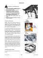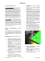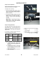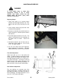
1
Double Windrow Attachment For M150 & M200 Tractors SET-UP INSTRUCTION / OPERATOR’S MANUAL / PARTS CATALOG January, 2009 Part #169216 $15 MACDON DOUBLE WINDROW ATTACHMENT MacDon M Series Windrower Tractor DOUBLE WINDROW ATTACHMENT TABLE OF CONTENTS Introduction ............................................................................................................................................. 1 Set-Up Instructions .......................................................................................................................2 - 14 Operation Safety Sign Locations........................................................................................................................ 14 Safety ................................................................................................................................................ 15 To Raise & Lower Deck..................................................................................................................... 15 Side Delivery Draper Speed.............................................................................................................. 15 Deck Angle ........................................................................................................................................ 16 Deck Height ....................................................................................................................................... 17 Conditioner Forming Shield Position................................................................................................. 18 Conditioner Rolls Position ................................................................................................................. 18 Operating Recommendations............................................................................................................ 19 Maintenance/Service Draper Tension Adjustment............................................................................................................... 20 Draper Tracking Adjustment.............................................................................................................. 20 Draper Replacement ......................................................................................................................... 21 Front Skid Adjustment ....................................................................................................................... 21 Rear Deflector Adjustment ................................................................................................................ 21 Draper Roller Maintenance ......................................................................................................... 22, 23 Lubrication ......................................................................................................................................... 23 Hydraulic Schematic.......................................................................................................................... 24 Repair Parts ........................................................................................................................................... 25 INTRODUCTION The double windrow attachment (DWA) allows the combining of two windrows of conditioned material close together to be picked up by a forage chopper. This unit may be mounted on the following MacDonbuilt windrower tractors: M150 & M200. The system is for use with Model A30, A40, R80 and D60 headers with HC10 hay conditioners. The conditioned crop is deposited onto the side delivery system draper and delivered to the side of the tractor when required. Raising the side delivery system shuts off the draper and allows the crop to be deposited between the tractor wheels as it would be without the side delivery system. Form 169216 1 January 2009 SET-UP INSTRUCTIONS NOTE: This unit fits only the tractor models listed on page 1. It can not be installed on the M100 tractor model. NOTE: This page refers to rework required for tractors built prior to Production Year 2008. For tractors built in 2008 and later, go to page 3. On pre-2008 built tractors: 1. If not present, drill four holes 0.781” diameter at the locations shown above. There are hydraulic hoses above the two rear holes. Make sure hoses are out of the way when drilling. Ream/grind rear holes to make them square for square neck bolts. Slots are only required if holes do not line up with double windrow attachment frame. Form 169216 2 January 2009 SET-UP INSTRUCTIONS 2. Install #12 ORB X #12 JIC fitting (A) to port “R2” on DWA (double windrow attachment) drive block. Install #10 ORB X #10 JIC fitting (B) to port “P” on DWA drive block. Draper Drive Block Installation Leave plastic plugs in these two ports. C 1. Move the left cab-forward platform to the open position for access to the hydraulic valve blocks. Ensure the platform latch is engaged in open position. 3. Install DWA drive block to tractor frame with 3/8” serrated flange head bolts (C). Fittings installed earlier point towards the tractor engine and relief valve on block points to rear of tractor. COOLER BY-PASS RELIEF VALVE D A A B D E SUPERCHARGE PUMP 4. Install hose (D), supplied in kit, to fitting (A) at DWA drive block. DWA DRIVE BLOCK E A B Form 169216 3 January 2009 SET-UP INSTRUCTIONS 5. Remove hose (E) from cooler by-pass relief valve next to oil filter and connect to fitting (B) on DWA drive block. The other end of hose is connected to the super charge pump. NOTE: Access to hose (E) can be from underneath tractor or by raising tractor hood and working from the left hand platform. Platform Rail Installation A S E B B 7. Remove right hand steps (S) from platform by loosening two top bolts (A) and removing two bottom bolts (B). Lift steps to detach at top keyhole slots (A). Retain bolts for next step. C D A D E 6. Install the other end of hose (D) to cooler bypass relief valve next to oil filter. This is where hose (E) was disconnected. Form 169216 B 8. Install rail weldment (C) to right hand platform as follows: Hang rail weldment (C) by engaging keyhole slots on top bolts (A). Install two bottom bolts (B) and tighten all four bolts. 4 January 2009 SET-UP INSTRUCTIONS Linkage Installation F E J G H F E A B A 9. Remove support (A) by removing nut (B). 13. M150: Mount support (A) to tractor frame with two 1/2 x 2-3/4 inch long hex head bolts (F), flatwashers (under bolt heads) and nuts (E). These bolts replace the engine mount bolts (D) removed in step 12. - From underneath, install a 3/4 x 3-1/2 inch long hex head bolt (G) with flat washer (H) under bolt head. Secure with flat washer, lock washer and nut on top side. - From top side, install a 3/4 x 5-1/2 inch long hex head bolt (J) with flat washer (H) under bolt head. Do not install nut on bolt (J). - Go to Step 16. C 10. Locate in hardware kit two carriage head bolts, 3/4 x 4-1/2” long. Install bolts (C) in tractor frame member between the engine and caster wheels. NOTE: Hoses will have to be moved to get the bolts in place. 11. If mounting on an M150 tractor, proceed with steps 12 and 13. If mounting on an M200 tractor, go to Step 14. D 12. M150: Remove the outer bolt and nut from the front engine mount at (D) on both left and right sides. Retain nuts for reuse. Form 169216 5 January 2009 SET-UP INSTRUCTIONS R80 A30/40 & D60 K 16. Support linkage assembly with a forklift. NOTE: Make sure fork is not lifting against cylinder fitting. Align linkage with 4 bolts in tractor frame. Mount linkage in the most forward position (shown) if used with an R80 header and mount in the most rearward position if used with A30/40 or D60 header. Install four flatwashers, lock washers and nuts at (K) and tighten D 14. M200: Remove four bolts (D) from the front engine mounts, two on left side and two on right side. Retain nuts for reuse. A M F E J L F F G H E F 15. M200: Mount support (A) to tractor frame with four 1/2 x 2-3/4 inch long hex head bolts (F), flatwashers (under bolt heads) and nuts (E). These bolts replace the engine mount bolts (D) removed in step 14. Note that outer two bolts (F) are installed with heads on topside and inner two bolts (F) are installed with heads underneath. - From underneath, install a 3/4 x 3-1/2 inch long hex head bolt (G) with flat washer (H) under bolt head. Secure with flat washer, lock washer and nut on top side. - From top side, install a 3/4 x 5-1/2 inch long hex head bolt (J) with flat washer (H) under bolt head. Do not install nut on bolt (J). Form 169216 L 17. Lower linkage by hand by first pulling on safety pin (M) on the LH side of linkage. Remove plugs at end of lift cylinder hoses (L) if needed to remove air from hoses. 6 January 2009 SET-UP INSTRUCTIONS Re-install nut (D) with washer (E). Washers are supplied in hydraulic kit. R80 F J A30/40 & D60 H G 21. Remove shipping stand (F) at rear of deck by removing two nuts (G) and (H) and washers (J). Discard shipping stand and washers. Retain nuts for re-use. 18. Cylinder pivot must be in the lower hole (shown) for A30/40 or D60 headers and upper hole for R80 headers. Move pin to upper hole if used with R80. Deck Installation L K B A B 22. Remove shipping stand (K) by removing wire (L). Discard shipping stand. 23. Deck is now ready to be assembled to the linkage underneath the tractor. Position deck on RH side of tractor. 19. Remove 2X4 (A) by removing banding (B) and discard. E D C Fork lift 20. Support deck with fork lift. Forks should be inboard of shipping stand (C). Remove two shipping stands (C) at front deck by removing nut (D). Discard shipping stands. Form 169216 7 24. Support deck with a floor jack or fork lift at each end and position the deck pivot (M) in to the linkage clevis (N). Make sure there is a loose bushing inside the deck pivot. January 2009 SET-UP INSTRUCTIONS P M N 100 mm or 4” R H G 27. Adjust turnbuckle (Q) length so the deck is approximately 100 mm or 4” from the right hand drive tire. The turnbuckle length should be about 530 mm long for the R80 header and 630 mm long for the A30/40 or D60 header. Note: The lift cylinder is single acting and it is pressurized with the draper drive circuit. Therefore when the deck is setup for the R80 the tractor needs to be running for the deck to be in its most forward position. This adjustment can be fine-tuned when the hydraulics setup is complete. 25. Align the deck pivot with holes in clevis by raising or lowering the floor jack and insert shaft (P). At bottom install one regular hex nut (H) and torque the nut to 250 ft-lbs. Then install lock nut (G) and tighten against nut (H). It is important that these nuts are properly torqued. Add grease to grease zerk (R). R80 R S Q A30/40 & D60 T 26. Attach turnbuckle (Q) from linkage to deck. Use outer pivot (shown) if used with A30/40 or D60 header and use inner pivot if used with an R80 header. S T 28. Raise backsheet (R) on deck and install gas shock (S) in center hole with nut (T). Form 169216 8 January 2009 SET-UP INSTRUCTIONS Hydraulics Installation HYDRAULICS OVERVIEW See following pages 9 to 11 for detailed installation instructions. Balloons above match callouts on photos on pages 9 to 11. See Maintenance/Service Section, page 22 for Hydraulic Schematic Form 169216 9 January 2009 SET-UP INSTRUCTIONS 31. The installation of case drain hose (G) depends on the header configuration. See steps 28-31. Hydraulics Installation (continued) A30/40 & R80 H B A J 29. .Install #10 ORB X #10 JIC elbow (A) in port “DWA” on draper drive block. Install #12 ORB X #10 JIC elbow (B) in port “R1”. A G 32. On A30/40 without reverser kit or R80 headers, connect case drain hose (G) to “T” port on the header drive block. First connect #12 ORB X #10 JIC elbow (H) to port “T”, then install #10 JIC X #6 JIC reducer (J) to elbow (H). Finally install hose (G) to reducer (J). B F A30/40 with reverser U C J E G D G Reverser 33. On A30/40 headers with reverser kit, connect case drain hose (G) to “T” port on the header drive block. First connect #12 ORB X #10 JIC elbow (H) to port “T”, then install #10 JIC X #10 JIC elbow (U) to elbow (H) followed by #10 JIC X #6 JIC reducer (J). Finally install hose (G) to reducer (J). Make sure hose (G) is not rubbing against any fittings. C D 30. Install #10 tee (F) to elbow (B) as shown. Install pressure hose (C) from draper drive motor to elbow (A). Install return hose (D) to tee (F). Install ½” lift cylinder hose (E) to tee (F). Form 169216 H 10 January 2009 SET-UP INSTRUCTIONS K D60 with reverser D60 K J H G U J Reverser G 35. On D60 headers with reverser kit, connect case drain hose (G) to “T” port on the header drive block. Disconnect the reel return hose which is connected to port “T” and all the fittings in between. First connect #12 ORB X #10 JIC elbow (H) to port “T”, then install #10 JIC tee (K) to elbow (H) followed by #10 JIC X #6 JIC reducer (J). Finally install hose (G) to reducer (J). Make sure hose (G) is not rubbing against any fittings. Re-connect reel return hose by first installing elbow (which was removed earlier) to tee (K) followed by reel return hose. 34. On D60 headers without reverser kit, connect case drain hose (G) to “T” port on the header drive block. Disconnect the reel return hose which is connected to port “T” and all the fittings in between. First connect #12 ORB X #10 JIC elbow (H) to port “T”, then install #10 JIC tee (K) to elbow (H) followed by #10 JIC X #10 JIC elbow (U) then #10 JIC X #6 JIC reducer (J). Finally install hose (G) to reducer (J). Re-connect reel return hose by first installing elbow (which was removed earlier) to tee (K) followed by reel return hose. Form 169216 H 11 January 2009 SET-UP INSTRUCTIONS 38. Install #6 ORB X #6 JIC elbow (R) in to port “K” on valve block (P). Route ¼” lift cylinder hose (S) through side of tractor frame and connect to elbow (R). Install plug (T) into port “J”. 39. Neatly route the hoses by using the zip ties that are included in the kit. Make sure hoses are not rubbing against any moving parts M L Electrical Installation 36. Remove plugs (L) and (M) from the lift manifold block and retain. C B P N L A M 40. Connect DWA harness from linkage to plug (A) on the draper drive block. Connect the other plug on DWA harness to P74 on the tractor harness, located near the valve block. 41. Find plug P73 on the tractor harness and connect to plug (B) on the lift block. This is valve “4C”. Find plug P72 and connect it to plug (C), this is valve “2C”. 37. Install auxiliary valve block (P) to the lift manifold block. If installing with a D60 header with reel fore/aft, it will already have an auxiliary valve block. The new block (P) gets mounted next to the existing one. Apply grease to o-rings supplied with valve block and install them in the countersunk port holes where the plugs were removed. Assemble smooth side of valve (P) to lift valve with four 3/8” bolts (N) provided. Use the longer bolts if there are two auxiliary valve blocks. Torque bolts to 25 ft-lbs. A P S B T R Form 169216 42. Inside tractor cab, remove cover (A) from console by removing 5 screws (B). 12 January 2009 SET-UP INSTRUCTIONS C F 46. Install rocker switch (F) in cover. The side with the prongs should be next to the operator’s seat. H 43. Cut hole in decal and install rotary switch (C) as shown. The hole is already present in the mounting plate. G 47. Install rocker switch into plug (G) and install rotary switch into plug (H). These plugs come with the tractor and are inside the console. 44. Remove knockout in cover (A) for rocker switch. File down the burrs. D B A E 48. Re-install cover (A) with five screws (B). 45. Install knob (D) on rotary switch (C). Tighten set screw in knob with Allen wrench (E). Form 169216 13 January 2009 SET-UP INSTRUCTIONS SAFETY SIGN LOCATIONS PROGRAM ARROWS SELECT 49. The program in the tractor monitor needs to be changed to recognize the DWA. a. Turn the key on. Press PROGRAM and SELECT at the same time. Select YES for Tractor Setup. Toggle between YES and NO by pressing the ARROWS. b. Scroll through the menu until display reads “DWA INSTALLED?” and select YES. c. Display will then read “SWAP DWA CONTROLS?” PART NO. 172736 – PINCH POINT LOCATED ON LINKAGE ARM (BOTH SIDES) REEL FORWARD DWA DOWN REEL UP REEL DOWN REEL AFT DWA UP PART NO. 134070 – HIGH PRESSURE HYDRAULICS LOCATED ON DECK d. The option exists to raise and lower the DWA with either the reel fore/aft switch or the rocker switch (F) installed earlier. If YES is selected, the DWA up/down will be controlled with the reel fore/aft switch and reel fore/aft (D60 headers only) will be controlled with the rocker switch. If NO is selected, the DWA up/down will be controlled with the rocker switch. e. The display will then read “EXIT DWA MENU?” Select YES. Press PROGRAM to revert monitor back to operating mode. Form 169216 14 January 2009 OPERATION CAUTION: To avoid bodily injury: 1. Review the safety sections of your tractor and header Operator’s Manuals. 2. Keep all shields in place. 3. Engage safety pin (A) when deck is raised fully for transport, service and storage or before going under deck for any reason. To engage safety pin, raise deck, rotate pin and push in until both roll pins (B) are inside channel. 4. Keep away from moving draper and rollers. 5. Keep clear of the deck while it is being raised or lowered. A B SAFETY PIN To raise and lower deck: DWA DOWN NOTE: Extra caution should be taken when raising the deck for the first time. The deck rotates as it raises and lowers and the backsheet folds on to the deck. Make sure the deck and backsheet are not interfering with any tractor parts or the forming shield. DWA UP In the setup instructions, if you chose to swap the DWA controls, use the reel fore/aft switch to raise and lower the deck. The deck moves forward when lowering, so switch operation will be the same as when moving the reel forward. The deck moves rearward when raising so switch operation will be the same as when moving the reel rearward. DRAPER SPEED In the setup instructions, if you chose “NO” to swap the DWA controls, use the rocker switch installed in the console. Press the rocker switch forward portion to lower the DWA and press the rocker switch rearward portion to raise the DWA. NOTE: Draper shuts off automatically when deck is raised about two thirds of the way up. If deck does not shut off soon enough, resulting in backsheet touching draper before it shuts off, the switch at the linkage needs to be lowered. Lower switch by loosening two screws (C). Do not over tighten the screws or the switch will not work. DWA DOWN DECK LIFT CONTROLS Side delivery draper speed: C To set the draper speed, turn the draper speed control. DRAPER SHUT-OFF SWITCH Form 169216 15 January 2009 OPERATION To adjust deck angle: The deck angle relative to the right hand drive tire is adjustable with turnbuckle (Q). A distance of 100 mm (4”) from the deck to the tire is recommended. To adjust the turnbuckle, loosen the locking tab and rotate center tube to desired length then re-lock tab against tube. NOTE: If setup with an R80 header, the deck will only be in its most forward position when the tractor is running. The lift cylinder is single acting so it is not pressurized in the down stroke when the tractor is shut off. When the tractor is running there is a supply of low pressure oil to move the deck forward. 100 mm or 4” R80 Q The deck angle relative to the ground should be horizontal or at a slight incline. Distance (C) should be equal to or greater than (D). If used with an R80 header in lighter crop, distance (C) should be equal to (D). If the crop needs to be thrown farther, increase distance (C). A30/40 & D60 DECK ANGLE TO TIRE To adjust the deck angle loosen four ¾” bolts (E) and then loosen nut (F). Adjust draw bolt by tightening the second nut (F) if you want to increase distance (C) and loosen nut if you want to decrease distance (C). Once done adjusting, tighten nut (F) and then tighten four bolts (E). The four ¾” bolts must be torqued to 245 ft-lbs. D C DECK ANGLE TO GROUND E E F Form 169216 16 January 2009 OPERATION To adjust deck height: The deck should never touch the ground or excessive wear could occur to some deck components. If the deck is too low to the ground, raise it as follows: Lower linkage by fully extending cylinder. Move bottom pivot pin to lower position (R). This will raise the front of the deck approximately 100 mm (4 inches). R Draper tracking: Draper tracking needs to be checked when the draper is first run-up otherwise damage to the draper can occur. See Draper Adjustment in the Maintenance/Service section on how to adjust the tracking. Form 169216 17 January 2009 OPERATION Conditioner Forming Shield Position: K J L G DECK LOWERED Adjust rear deflector baffle (H) so the crop flow does not interfere with the deck when it is fully raised. H Crop Flow DECK RAISED L Make sure forming shield is high enough to clear the deck when it is lowered (G). Adjust the forming shield height by removing hair pin (J) and moving strap (K) to desired position. The forming shield should be as low as possible without interfering with deck. L Fins (M) underneath the forming shield can affect the crop flow. It is recommended to remove fins, especially with an R80 in light crop. Conditioner Rolls Position: The left hand side deflector (L) should be in the widest position to not affect crop flow. If center delivering, the left hand deflector can be moved in to make a narrower windrow. The right hand side deflector should be in the widest position to not affect the crop flow because this is where the deck is the furthest from the conditioner rolls. Form 169216 M The gap between the conditioner rolls needs to be small enough to properly throw the crop on to the double windrow attachment. The gap is dependant on crop type and yield. If the gap is too little for heavy crops, this consumes excessive engine power and is hard on all the components affected. If the gap is too large, the crop will not have enough velocity to reach the side delivery deck. See conditioner operator’s manual for adjustment procedure. 18 January 2009 OPERATION may need to be lower for center windrowing. b. If there are fins on the rear baffle, remove them to prevent interference with the crop flow. c. Header angle: The steeper the header angle, the higher the arc of the crop trajectory will be. Header angle should be set such that the crop is projected at a maximum arc height without excessive contact with the top forming shield. It may be possible to shoot crop above the forming shield with extreme header angle and rear baffle positions. In rocky conditions where DWA is necessary, a high skid shoe kit or adjustment to gauge rollers may be required to achieve correct stubble height and also maintain crop trajectory. d. Header height: affects the header angle. Target should be to have the lift linkage fully down at all times. e. The roll gap should be small enough to properly grab the crop and throw it. f. The roll speed which is mechanically tied to the disc speed can affect how fast the crop gets projected. This again should be in the recommended range. Operating Recommendations: 15’, 16’, 18’, 20’ Headers: On the first pass, the side delivery system is raised and crop is deposited between tractor wheels. On the return pass, the side delivery system is lowered and crop is deposited outside of the tractor wheels to the right, beside the previously laid windrow. Position of the crop can be adjusted by using the side deflectors on the forming shields when depositing the crop in the center and by varying the draper speed when depositing the crop to the side. The faster the draper speed is set, the farther the crop will be delivered to the side. 25’, 30’ Headers: The side delivery system is lowered at all times. Crop is deposited outside the tractor wheels and laid beside the previously deposited windrow on return pass. Position of the crop can be adjusted by varying the draper speed when depositing the crop to the side. One can also raise the side delivery system and center deliver all the time. Operating Header: Recommendations with R80 The conditioner rolls on an R80 header are further ahead than all other headers; therefore delivering light crop from the conditioner rolls to the side delivery deck may require special attention: A There are three areas that can affect the crop flow to the deck: B 1. Crop flow from the cutterbar to the rolls. a. Header cut width must be kept as full as possible on the right hand side. Any less than 75% may have adverse effects on feeding. b. Feed plates must be installed for appropriate crop. They are required for forage but not for alfalfa. (See R80 Operator’s Manual.) c. Higher ground speeds will usually result in better crop flow from the conditioner rolls to the deck. Ground speed should be a minimum of 6 mph (10 km/h) for light crops. d. Disc speed must be in recommended range for specific crop/yield. (See R80 operator’s manual.) Crop flow from rolls to forming shield. a. Rear baffle on the R80 header should be in the upmost position. However it Form 169216 3. Forming shield settings: a. Make sure forming shield (B) is installed correctly with bracket (A). b. Buildup of sticky crop residue on deflector sliding surfaces should be periodically removed. c. See “Conditioner Forming Shield Position” on previous page. 2. 19 January 2009 MAINTENANCE/SERVICE Draper Tension Adjustment: C B Draper tension should be just enough to prevent slipping and keep draper from sagging. Set draper tension as follows: 1. Check that draper guide (rubber track on under- side of draper) is properly engaged in groove of drive roller and that idler roller is between the guides. A 2. Turn bolt (A) clockwise (tighten) and white indicator bar (B) will move to the right in direction of arrow to indicate that draper is tightening. Tighten until bar is about halfway in window. IMPORTANT: To avoid premature failure of draper, draper rollers and/or tightener components, do not operate with tension set so that white bar is not visible. E D Draper Tracking Adjustment: The draper deck has one fixed roller and one spring-loaded roller. The spring loaded roller is located at the same end of the deck as the draper tensioner. Both rollers can be aligned by adjuster rods. If the draper is tracking incorrectly, make the following adjustments to the rollers: TRACKING AT LOCATION Rearward ADJUSTMENT INCREASE ‘W’ Drive Roller Forward DECREASE ‘W’ Rearward INCREASE ‘Y’ Idler Roller Forward DECREASE ‘Y’ METHOD Tighten Nut ‘H’ Loosen Nut ‘H’ Tighten Nut ‘E’ Loosen Nut ‘E’ a) To adjust the idler roller: Loosen nut (C) and then loosen nut (D). Adjust nut (E) according to chart and then tighten nuts (D) and (C). b) To adjust the drive roller: Loosen two nuts (F) and then loosen nut (G). Adjust nut (H) according to chart and then tighten nuts (G) and (F). c) After adjusting the alignment adjust the tension of the draper. Form 169216 G 20 H F January 2009 MAINTENANCE/SERVICE DANGER To avoid bodily injury or death from unexpected start-up or fall of raised machine, stop engine, remove key and engage safety pin before going under machine for any reason. Replacing Draper: 1. Raise deck partly up to increase space between deck and right hand drive tire. First remove front skid (J) by removing four nuts (K). K J 2. Loosen draper tension and push idler roller inwards as far as possible. 3. Disconnect turnbuckle (Q) and allow deck to rotate rearwards to increase space between deck and tire. 4. Pull off old draper and slide on new one. The draper is bi-directional so the orientation of the draper does not matter. Tension the draper. 5. Re-install turnbuckle (Q) and front skid (J). Adjust front skid to achieve a 1.5 to 3.0 mm (1/16 - 1/8”) gap to draper. Q 6. Run the new draper and check alignment, adjust alignment if necessary. Re-check draper tension after it has run for a few hours. M Front Skid Adjustment: L Adjust front skid (J) so it is just above the draper. To adjust, loosen four nuts (K) on front of skid, position skid height and retighten nuts. The skid height should be 1.5 to 3.0 mm (1/16 1/8”) above the draper. The weight of the skid should not be on the draper; otherwise it will cause excessive heat and melt the draper. If gap is excessive, crop can enter inside draper. Rear Deflector Adjustment: K The rear deflector (L) prevents crop from entering inside draper. To adjust, loosen all nuts (M) along the length of the deck and raise or lower accordingly. The height should be 1.5 to 8 mm (1/16 – 5/16”) above the draper. Form 169216 J 21 January 2009 MAINTENANCE/SERVICE Draper Roller Maintenance: The draper rollers have non-greaseable bearings. The external seal should be checked every 200 hours or more frequently in sandy conditions to obtain the maximum bearing life. Remove front skid to inspect seals. N DANGER To avoid bodily injury or death from unexpected start-up or fall of raised machine, stop engine, remove key and engage safety pin before going under machine for any reason. P Drive Roller: 1. Raise deck and engage safety pin. 2. Remove front skid, loosen and remove draper. See page 21 for instructions. 3. Loosen two jam nuts (N) and set screws (P). 4. At the front of the drive roller (S) remove bolt and washer (R). The arm can be pulled out of the deck. 5. Pull drive roller off of motor shaft. 6. Re-install drive roller in reverse order. 7. Apply grease to motor shaft. 8. Slide drive roller on to motor shaft. Make sure it is fully engaged. The drive roller should be 33 mm (1.3”) from the face of the motor. 9. Install two set screws (P) with jam nuts. Torque set screws to 20 ft-lbs (27 N-m). 10. Torque bolt (R) to 70 ft-lbs (95 N-m). S R Idler Roller: 1. Raise deck and engage safety pin. 2. Remove front skid. Loosen draper. Draper does not need to be removed but removal will ease roller disassembly. 3. Remove idler roller (T) by removing bolt and washer (R) at each end of roller. 4. Re-install idler roller in reverse order. 5. Torque bolts (R) to 70 ft-lbs (95 N-m). T R Form 169216 22 January 2009 MAINTENANCE/SERVICE 6. Install seal into roller by pushing on the outer and inner race of the seal. A flat washer (1.0” ID X 2.0” OD) works well to push against the seal. The seal is fully positioned when the 3 mm (0.12”) dimension is achieved. 7. Make sure bearing and seal turn freely. Re-install roller assembly in to deck. Draper Roller Bearing/Seal Replacement: 1. Remove roller assembly. See previous section for instructions. C B A Lubrication: There are 5 pivots which require greasing every 250 hours and/or after end of season. 2. Remove bearing assembly (B) and seal (A) from roller tube (C) as follows: a. Attach a slide hammer to threaded shaft. b. Tap out the bearing assembly. 3. Clean inside of roller tube (C). Check tube for wear or damage. Replace if necessary. B A 4. Install bearing assembly (B) into roller by pushing on outer race of bearing. The bearing is fully positioned when the 14 mm (0.55”) dimension is achieved. 5. Apply grease in front of bearing. Form 169216 23 January 2009 MAINTENANCE/SERVICE Hydraulic Schematic Form 169216 24 January 2009 REPAIR PARTS TABLE OF CONTENTS Deck, Draper & Rollers .....................................................................................................................26 - 29 Deck Supports & Linkage..................................................................................................................30 - 33 Hydraulics and In-Cab Electrical........................................................................................................34, 35 Hydraulic Service Components..........................................................................................................36, 37 Decals ......................................................................................................................................................38 Numerical List ..........................................................................................................................................39 Serial Number Record the serial number in the space provided. Plate is located on deck at (A). NOTE: When ordering parts and service, be sure to give your dealer the complete and proper serial number. A Form 169216 25 January 2009 DECK, DRAPER & ROLLERS (Illustration 1) 75 43 1 52 53 3 5 2 45 63 49 35 59 62 34 63 51 63 37 36 25 33 26 50 63 6 61 55 4 27 Form 169216 54 26 January 2009 DECK, DRAPER & ROLLERS REF PART NUMBER 1 2 3 4 5 6 25 26 27 33 34 35 36 37 43 45 49 50 51 52 53 54 55 59 61 62 63 75 Form 169216 172730 172701 172700 115146 165281 134070 120449 120451 120462 145428 145361 145548 132531 132532 109791 19965 172259 30470 7663 30441 50190 20077 21491 137727 18599 42592 30228 14338 DESCRIPTION QTY DECK – complete with decals .................................................... DECAL – draper/auger position ................................................. DECAL – disc position................................................................ REFLECTOR – amber................................................................ DECAL – draper tension............................................................. DECAL – warning, hydraulic....................................................... MEMBER – left hand stabilizer weldment .................................. BELL CRANK WELDMENT – left hand...................................... MEMBER – compression weldment........................................... INDICATOR ................................................................................ NUT – special ............................................................................. SPRING – leaf (tensioner).......................................................... SPACER ..................................................................................... SPACER ..................................................................................... MOULDING ................................................................................ BOLT – round head, square neck, 3/8 NC x 1.0 GR 5 ZP ......... BOLT – shoulder, 3/8-16 UNC ................................................... BOLT – hex head, 1/2 NF x 1.0 GR 5 ZP................................... NUT – hex, lock, 1/2-20 UNF nylon patch ZP ............................ WASHER – hardened................................................................. BOLT – hex head (thread minimum) 5/8 NC x 7.5 LG GR 5 ZP BOLT – hex head, 3/8 NC x 1.0 LG GR 5 ZP ............................ BOLT – hex head, 1/2 NC x 1.25 LG GR 5 ZP .......................... NUT – hex jam, distorted thread, 1/2-13 UNC GR 5 ZP ............ WASHER – SAE flat, 17/32 ID x 1 1/16 inch OD ZP ................. WASHER – flat ........................................................................... NUT – flange, distorted thread, smooth face, 3/8-16 UNC ........ RIVET – blind 1/8 x 1/8............................................................... 1 1 1 1 1 1 1 1 1 1 1 1 1 1 1 1 1 1 1 8 1 1 1 1 1 1 4 2 27 SERIAL NUMBER January 2009 DECK, DRAPER & ROLLERS (Illustration 2) Form 169216 28 January 2009 DECK, DRAPER & ROLLERS REF PART NUMBER 7 8 9 10 11 12 13 14 15 16 17 18 19 20 21 22 23 24 28 29 30 31 32 38 39 40 41 42 44 46 47 48 56 57 58 60 63 64 65 66 67 69 70 71 72 73 74 144833 144494 144501 144499 176000 144837 165735 30441 145249 172259 144832 18709 18664 120845 145249 30441 145593 145345 144602 172747 115145 115147 145357 144652 144851 144558 144597 165304 37687 18598 19966 18604 50186 21471 18590 11695 30228 21066 18671 135157 176063 18593 18689 30695 132867 120572 50104 NOTES: 1. Form 169216 DESCRIPTION QTY ROLLER – idler weldment .......................................................... ROLLER – drive weldment ......................................................... ARM – support............................................................................ ARM – roller support................................................................... ARM – support weldment ........................................................... ARM – support rear .................................................................... PIN ASSEMBLY – draper roller.................................................. WASHER – hardened................................................................. BOLT – hex head, 5/8 NF x 1.0 LG GR 5 ZP............................. BOLT – shoulder, 3/8-16 UNC ................................................... MOTOR – hydraulic M & S 1.52 CI ............................................ SETSCREW – hex head, socket cup pt 3/8 NC x 5/8 LG .......... NUT – hex jam, 3/8-16 UNC GR 5 ZP ....................................... SEAL – Nilos LSTO steel disk .................................................... BOLT – hex head, 5/8 NF x 1.0 LG GR 5 ZP............................. WASHER – hardened................................................................. ROD – adjuster weldment .......................................................... ROD – adjuster weldment .......................................................... PANEL – rear weldment ............................................................. SKID – complete with reflectors ................................................. REFLECTOR – fluorescent red-orange ..................................... REFLECTOR – red..................................................................... BRACKET – idler arm................................................................. BAR – stiffener ........................................................................... DEFLECTOR – seal ................................................................... BUSHING – steel........................................................................ SEAL – backsheet ...................................................................... DRAPER – endless, DWA.......................................................... MOULDING ................................................................................ WASHER – SAE flat, 13/32 ID x 13/16 inch OD ZP .................. BOLT – round head, square neck, 3/8 NC x 1.25 LG GR 5 ZP . PIN – cotter 3/32 dia. x 3/4 ZP ................................................... NUT – flange, lock, smooth face, dist thd, 1/2-13 UNC ... GR 5 BOLT – round head, square neck, 1/2 NC x 1.25 GR 5 ZP ....... NUT – hex, 3/8-16 UNC GR 5 ZP .............................................. WASHER – flat ........................................................................... NUT – flange, distorted thread, smooth face, 3/8-16 UNC ........ BOLT – round head, square neck, 1/2 NC x 1 GR 5 ZP ............ FITTING – lube 1/4-28 UNF ....................................................... SCREW – machine..................................................................... SHAFT - threaded ..................................................................... NUT – hex, 3/4-10 UNC GR 5 ZP .............................................. NUT – hex, lock, distorted thread, 3/4-10 UNC.......................... FITTING – hydraulic connector .................................................. HOSE – hydraulic ....................................................................... HOSE – hydraulic ....................................................................... FITTING – elbow 90° hydraulic .................................................. 1 1 1 1 1 1 3 3 3 4 1 2 2 3 3 3 1 1 1 1 1 1 1 1 1 1 1 1 2 2 1 1 7 1 4 3 15 1 1 14 1 2 2 2 2 1 1 SERIAL NUMBER See Note 1 RE ITEM 67: Prior production units used a hex head bolt in this location. When replacing bolt with newer design threaded shaft, also order one each of nuts, items 69 and 70 for head end. 29 January 2009 DECK SUPPORTS & LINKAGE (Illustration 1) Form 169216 30 January 2009 DECK SUPPORTS & LINKAGE REF PART NUMBER 4 5 8 9 10 11 12 14 16 17 18 19 20 28 30 31 32 36 37 38 39 41 42 43 44 45 46 51 53 54 56 57 62 63 Form 169216 172746 172736 144592 144593 144594 172910 176018 176023 109699 110845 144826 176031 172664 144996 30816 18592 176009 30512 18626 18648 20312 18627 21354 22072 30228 19966 135158 135159 18671 30282 144805 172700 172701 172903 144870 DESCRIPTION QTY ARM – decal assembly............................................................... DECAL – warning DWA linkage ................................................. ARM – front weldment ................................................................ ARM – bottom weldment ............................................................ CLEVIS – weldment ................................................................... SHAFT ........................................................................................ SHAFT ........................................................................................ SHAFT ........................................................................................ SWITCH – snap action ............................................................... HARNESS – DWA...................................................................... CYLINDER – hydraulic ............................................................... SEAL KIT – for cylinder CLEVIS ....................................................................................... JOINT ASSEMBLY..................................................................... BOLT – round head, square neck, 5/8 NC x 5 TFL GR 5 ZP..... NUT – hex, 5/8-11 UNC GR 5 ZP .............................................. WASHER – Nordlock, 3/4" SP ................................................... BOLT – hex head, 3/4 NC x 2.0 LG GR 5 ZP ............................ PIN – clevis................................................................................. PIN – cotter, 3/16 dia. x 1.25 ZP ................................................ PIN – clevis................................................................................. PIN – clevis................................................................................. BOLT – hex head, 3/8 NC x 2.0 LG GR 5 ZP ............................ WASHER – flat ........................................................................... NUT – flange, distorted thread, smooth face, 3/8-16 UNC ........ BOLT – round head, sq. neck, 3/8 NC x 1.25 LG GR 5 ZP .... SCREW – pan head, #6-32 x 3/4 LG ......................................... NUT – Nyloc .............................................................................. FITTING – lube, 1/4-28 UNF ...................................................... FITTING – elbow 90° hydraulic .................................................. HOSE – hydraulic ....................................................................... DECAL – disc position................................................................ DECAL – draper/auger position ................................................. TUBE .......................................................................................... RAIL WELDMENT ...................................................................... 1 2 1 1 1 1 1 1 1 1 1 31 SERIAL NUMBER 1 1 1 2 4 4 1 4 1 2 4 1 5 1 2 2 4 1 1 2 2 1 1 January 2009 DECK SUPPORTS & LINKAGE (Illustration 2) Form 169216 32 January 2009 DECK SUPPORTS & LINKAGE REF PART NUMBER 1 6 7 11 13 15 21 22 23 24 25 26 27 29 33 34 35 40 41 43 47 48 49 50 52 55 58 59 60 61 Form 169216 144590 176062 172700 172701 172910 176016 144853 176026 112217 112218 103738 21491 50186 102266 18601 18593 30896 30549 30280 21354 30228 20535 21264 16266 2147 21805 144806 176060 18640 18599 21880 DESCRIPTION QTY SUPPORT WELDMENT KIT, consists of 176062, Items 15, 58 & hardware. .... 1 1 2 2 1 1 1 1 2 2 2 2 6 2 5 5 1 1 2 1 3 2 2 1 1 1 1 1 5 4 4 SUPPORT WELDMENT ............................................................ DECAL – disc position................................................................ DECAL – draper/auger position ................................................. SHAFT ........................................................................................ PIN – L........................................................................................ SUPPORT .................................................................................. CYLINDER – gas spring............................................................. STUD – ball ................................................................................ CLIP – ball stud .......................................................................... CLAMP – PVC insulated 13/16" tube size ................................. BOLT – hex head, 1/2 NC x 1.25 LG GR 5 ZP .......................... NUT – flange lock, smooth face, dist. thd, 1/2-13 UNC GR 5 .... BOLT – RHSSN, 3/4 NC X 4.5 LG GR 5 ZP .............................. WASHER – SAE flat, 13/16 ID x 1.5 inch OD ZP ..................... NUT – hex, 3/4-10 UNC GR 5 ZP.............................................. BOLT – hex head, 3/4-10 UNC x 3.50 LG.................................. BOLT – hex head, 3/4 NC x 5.5 LG GR 5 ZP........................... NUT – flange, side lock, smooth face, 5/16 NC GR 5 ZP .......... BOLT – hex head, 3/8 NC x 2.0 LG GR 5 ZP ............................ NUT – flange, distorted thread, smooth face, 3/8-16 UNC ........ WASHER – flat ........................................................................... BOLT – hex head, 3/8 NC x 1.25 LG GR 5 ZP .......................... PIN – spring, 1/4 dia. x 1.25 LG ................................................. PIN – spring, 1/4 dia. x 1.5 LG ................................................... FITTING – elbow hydraulic......................................................... HOSE – hydraulic ....................................................................... CHANNEL WELDMENT ............................................................ WASHER – lock, 3/4 ................................................................. WASHER – flat, 17/32 inch I.D. ................................................ BOLT – hex head, 1/2 NC x 2.75 long, Gr 5, ZP ..................... 33 SERIAL NUMBER -185859 185860 January 2009 HYDRAULICS & IN-CAB ELECTRICAL Form 169216 34 January 2009 HYDRAULICS & IN-CAB ELECTRICAL REF PART NUMBER 1 2 3 4 5 6 7 8 9 10 11 12 13 14 15 16 17 18 19 20 21 22 23 24 25 Form 169216 163694 110575 144807 21843 50221 50102 21830 30695 30282 30556 118084 30994 132867 120572 50104 144805 144806 21805 REF REF 109575 109718 109773 21821 21568 10948 DESCRIPTION QTY MANIFOLD-DWA DRIVE, see next page for service parts............. VALVE BLOCK AUX LIFT, see next page for service parts .......... HOSE – HYDRAULIC ..................................................................... FITTING - ELBOW 90° HYD ........................................................... FITTING - ELBOW 90° HYD ........................................................... FITTING - HYD TEE........................................................................ FITTING - CONNECTOR HYD ....................................................... FITTING - CONNECTOR HYD ....................................................... FITTING - ELBOW 90° HYD ........................................................... FITTING - ELBOW 90° HYD ........................................................... FTG - HYD REDUCER.................................................................... PLUG- HEX CW O-RING................................................................ HOSE-HYD ..................................................................................... HOSE-HYD ..................................................................................... FITTING - ELBOW 90° HYD ........................................................... HOSE – HYDRAULIC ..................................................................... HOSE – HYDRAULIC ..................................................................... FITTING - ELBOW HYD.................................................................. MOTOR - SEE "DRAPER & DECK" CYLINDER - SEE "DECK SUPPORTS & LINKAGE" SWITCH - ROCKER, MOM-OFF-MOM .......................................... GAUGE-POTENTIOMETER ........................................................... KNOB – PLASTIC ........................................................................... BOLT - HH FLG (SERR FACE) 3/8 NC X 0.75 GR 5 ZP................ BOLT - HH 3/8 NC X 3.0 LG – units with 1 aux. drive block........... BOLT - HH 3/8 NC X 5.5 LG – units with 2 aux. drive blocks ......... 1 1 1 1 2 2 1 3 2 1 1 1 2 1 1 1 1 1 35 SERIAL NUMBER 1 1 1 2 4 4 January 2009 HYDRAULIC SERVICE COMPONENTS Form 169216 36 January 2009 HYDRAULIC SERVICE COMPONENTS REF PART NUMBER 1 2 3 4 5 6 7 8 9 10 11 12 13 14 15 16 17 Form 169216 DESCRIPTION QTY 163694 49846 162285 163166 162283 162284 163159 163156 162286 158174 163149 163173 163178 162287 MANIFOLD-DWA DRIVE ................................................................ SEAL KIT VALVE-RELIEF ............................................................................... CONTROL-PROPORTIONAL FLOW ............................................. VALVE-DIFF PRESS SENSING ..................................................... SEAL KIT #10 3 WAY-SHORT ....................................................... FITTING-ZERO LEAK GOLD.......................................................... FITTING-ZERO LEAK GOLD.......................................................... PLUG-ORIFICE............................................................................... PLUG - HEX SOCKET CW O-RING ............................................... FITTING-ZERO LEAK GOLD.......................................................... COIL-ASSEMBLY ........................................................................... SEAL KIT PLUG-ORIFICE............................................................................... 1 110575 49846 163142 163156 163143 163160 163155 163154 163191 VALVE BLOCK AUX LIFT............................................................... SEAL KIT VALVE-SOLENOID ......................................................................... FITTING-ZERO LEAK GOLD.......................................................... VALVE-SOLENOID ......................................................................... SEAL KIT......................................................................................... COIL-TOUGH.................................................................................. COIL-TOUGH.................................................................................. NUT-COIL 37 SERIAL NUMBER 1 1 1 1 2 2 1 1 1 1 1 1 1 1 1 1 1 1 1 January 2009 DECALS 1 3 2 4 6 5 REF PART NUMBER DESCRIPTION QTY 1 2 3 172701 172700 115146 115145 115147 DECAL – draper/auger position.................................................. DECAL – disc position ................................................................ REFLECTOR – amber................................................................ REFLECTOR – fluorescent red-orange...................................... REFLECTOR – red..................................................................... 4 4 1 1 1 4 5 6 165281 134070 172736 DECAL – draper tension............................................................. DECAL – warning, hydraulic....................................................... DECAL – warning, DWA linkage ............................................... 1 1 2 Form 169216 38 SERIAL NUMBER January 2009 NUMERICAL LIST PART NO. 2147 7663 10948 11695 14338 16266 18590 18592 18593 18593 18598 18599 18599 18601 18604 18626 18627 18640 18648 18664 18671 18671 18689 18709 19965 19966 19966 20077 20312 20535 21066 21264 21354 21354 21471 21491 21491 21568 21805 21805 21821 21830 21843 21880 22072 30228 30228 30228 30228 Form 169216 PAGE PART NO. PAGE PART NO. PAGE PART NO. PAGE 33 27 35 29 27 33 29 31 29 33 29 27 33 33 29 31 31 33 31 29 29 31 29 29 27 29 31 27 31 33 29 33 31 33 29 27 33 35 33 35 35 35 35 33 31 27 29 31 33 30280 30282 30282 30441 30441 30441 30470 30512 30549 30556 30695 30695 30816 30896 30994 37687 42592 49846 49846 50102 50104 50104 50186 50186 50190 50221 102266 103738 109575 109699 109718 109773 109791 110575 110575 110845 112217 112218 115145 115145 115146 115146 115147 115147 118084 120449 120451 120462 120572 33 31 35 27 29 29 27 31 33 35 29 35 31 33 35 29 27 37 37 35 29 35 29 33 27 35 33 33 35 31 35 35 27 35 37 31 33 33 29 38 27 38 29 38 35 27 27 27 29 120572 120845 132531 132532 132867 132867 134070 134070 135157 135158 135159 137727 144494 144499 144501 144558 144590 144592 144593 144594 144597 144602 144652 144805 144805 144806 144806 144807 144826 144832 144833 144837 144851 144853 144870 144996 145249 145249 145345 145357 145361 145428 145548 145593 158174 162283 162284 162285 162286 35 29 27 27 29 35 27 38 29 31 31 27 29 29 29 29 33 31 31 31 29 29 29 31 35 33 35 35 31 29 29 29 29 33 31 31 29 29 29 29 27 27 27 29 37 37 37 37 37 162287 163142 163143 163149 163154 163155 163156 163156 163159 163160 163166 163173 163178 163191 163694 163694 165281 165281 165304 165735 172259 172259 172664 172700 172700 172700 172700 172701 172701 172701 172701 172730 172736 172736 172746 172747 172903 172910 172910 176000 176009 176016 176018 176023 176026 176031 176060 176062 176063 37 37 37 37 37 37 37 37 37 37 37 37 37 37 35 37 27 38 29 29 27 29 31 27 31 33 38 27 31 33 38 27 31 38 31 29 31 31 33 29 31 33 31 31 33 31 33 33 29 39 January 2009