1
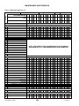
A30-S and A30-D
Pull-Type Mower Conditioners
A30-S, A30-D and A40-D
Self-Propelled Auger Headers
OPERATOR’S MANUAL
Revision C
Part #169000 $15
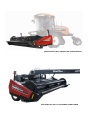
MACDON A40-D SELF-PROPELLED AUGER HEADER
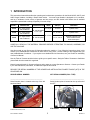
MACDON A30-D PULL-TYPE MOWER CONDITIONER
1 INTRODUCTION
This instructional manual describes the operating and maintenance procedures for the Model A30-S, A30-D, and
A40-D Auger Headers, including a Grass Seed version. Your new Auger Header is designed to cut, condition,
and lay in windrows a wide variety of grasses and hay crops, and the double knife feature that is available
expands the operational envelope, especially in heavier crops.
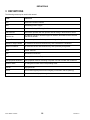
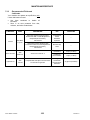
MODEL *
DESCRIPTION
A30-S
A - Auger Header
with Conditioner
A30-D
A - Auger Header
with Conditioner
A40-D
A - Auger Header
with Conditioner
CONFIGURATION
30 - Self-Propelled
Or Pull-Type
KNIFE
SIZE (FT)
FEATURES
S - Single
14 and 16
Hydraulic Drive
14, 16 and 18
Hydraulic Drive
14, 16, and 18
Separate Hydraulic Auger,
Knife and Reel Drives,
Grass Seed Option.
D - Double
40 - Self-Propelled
* Model availability depends on Dealer affiliation.
CAREFULLY READ ALL THE MATERIAL PROVIDED BEFORE ATTEMPTING TO UNLOAD, ASSEMBLE, OR
USE THE MACHINE.
Use this manual as your first source of information about the machine. If you follow the instructions given in this
manual, your Header/Mower Conditioner will work well for many years. A Parts Catalog is also supplied with your
new Header/Mower Conditioner. If you require more detailed service information, see your Dealer for availability
of a Service Manual.
Use the Table of Contents and the Index to guide you to specific areas. Study the Table of Contents to familiarize
yourself with how the material is organized.
Keep this manual handy for frequent reference and to pass on to new Operators or Owners. Contact your Dealer
if you need assistance, information, or additional copies of this manual.
RECORD THE SERIAL NUMBERS OF THE HEADER AND ARTICULATING POWER TONGUE (APT) IN THE
SPACES BELOW.
HEADER SERIAL NUMBER:
APT SERIAL NUMBER (PULL-TYPE):
_______________________________________
_________________________________________
Serial Number plate is located at the top of the left
hand end frame.
Serial Number plate is located at the top aft end of
the APT.
Published: November, 2010
PTO SPEED:
Form 169000 / 169040
1
540 RPM
1000 RPM
Revision C
TABLE OF CONTENTS
Section/Title
1 2 3 4 5 6 Page
INTRODUCTION ............................................................................................................................................... 1 SAFETY ............................................................................................................................................................ 6 2.1 SAFETY ALERT SYMBOL .................................................................................................................. 6 2.2 SIGNAL WORDS ................................................................................................................................ 6 2.3 SAFETY SIGNS .................................................................................................................................. 6 2.3.1 Safety Sign Installation ................................................................................................................ 6 2.3.2 3-Panel Safety Sign Locations: Pull-Type................................................................................... 7 2.3.3 3-Panel Safety Sign Locations: Self-Propelled ......................................................................... 10 2.3.4 2-Panel Safety Sign Locations: Self-Propelled ......................................................................... 12 2.4 GENERAL SAFETY .......................................................................................................................... 14 DEFINITIONS .................................................................................................................................................. 16 COMPONENT IDENTIFICATION ................................................................................................................... 17 4.1 PULL-TYPE ....................................................................................................................................... 17 4.2 SELF-PROPELLED........................................................................................................................... 20 SPECIFICATIONS .......................................................................................................................................... 21 5.1 PULL-TYPE HEADERS .................................................................................................................... 21 5.2 SELF-PROPELLED HEADERS ........................................................................................................ 23 OPERATION ................................................................................................................................................... 25 6.1 OWNER/OPERATOR RESPONSIBILITIES ..................................................................................... 25 6.2 OPERATIONAL SAFETY .................................................................................................................. 25 6.3 TRACTOR SETUP: PULL-TYPE ...................................................................................................... 26 6.3.1 Tractor Requirements ............................................................................................................... 26 6.3.2 Drawbar Adjustment .................................................................................................................. 26 6.3.3 Drawbar Hitch Set-Up ............................................................................................................... 27 6.3.4 3 Point Hitch (Cat. II, III, or IIIN) Set-Up .................................................................................... 28 6.4 MOWER CONDITIONER / TRACTOR HOOKUP: PULL-TYPE ....................................................... 29 6.4.1 Drawbar Hook-Up ..................................................................................................................... 29 6.4.2 3 Point Hitch (Cat. II, III, or IIIN) Hook-Up ................................................................................. 30 6.4.3 Hydraulic Connections .............................................................................................................. 32 6.5 MOWER CONDITIONER / TRACTOR UNHOOK: PULL-TYPE ....................................................... 33 6.5.1 Drawbar Hitch Unhook .............................................................................................................. 33 6.5.2 3-Point Hitch Unhook ................................................................................................................ 35 6.6 HEADER ATTACHMENT: SELF-PROPELLED ................................................................................ 36 6.6.1 A30-S, A30-D ............................................................................................................................ 36 6.6.2 A40-D ........................................................................................................................................ 38 6.6.3 Configure Reverser Valve Jumper Hose .................................................................................. 47 6.7 HEADER DETACHMENT: SELF-PROPELLED ............................................................................... 49 6.7.1 A30-S, A30-D Detachment........................................................................................................ 49 6.7.2 A40-D Detachment .................................................................................................................... 50 6.8 TRANSPORTING MOWER CONDITIONER .................................................................................... 52 6.8.1 Self-Propelled ............................................................................................................................ 52 6.8.2 Pull-Type: Towing ..................................................................................................................... 52 6.8.3 Pull-Type: Flatbed ..................................................................................................................... 55 6.9 BREAK-IN PERIOD........................................................................................................................... 60 6.10 PRE-SEASON CHECK ..................................................................................................................... 60 6.11 DAILY START-UP CHECK ............................................................................................................... 60 6.12 SHUTDOWN PROCEDURE ............................................................................................................. 61 Form 169000 / 169040
2
Revision C
TABLE OF CONTENTS
6.13 ENGAGING THE PTO: PULL-TYPE................................................................................................. 61 6.14 LIFT CYLINDER LOCK-OUTS .......................................................................................................... 61 6.14.1 Self-Propelled ............................................................................................................................ 61 6.14.2 Pull-Type ................................................................................................................................... 61 6.15 STEERING: PULL-TYPE .................................................................................................................. 62 6.15.1 Right Side Operation: Pull-Type ............................................................................................... 62 6.15.2 LH Side Operation: Pull-Type ................................................................................................... 63 6.15.3 Avoiding Obstacles ................................................................................................................... 63 6.15.4 Square Corners ......................................................................................................................... 63 6.15.5 180 Degree Turn ....................................................................................................................... 64 6.16 UNPLUGGING THE HEADER / MOWER CONDITIONER .............................................................. 65 6.16.1 Unplugging Conditioner: Pull Type ........................................................................................... 65 6.16.2 Unplugging Conditioner: Self-Propelled, A30-S and A30-D ..................................................... 65 6.16.3 Unplugging Sickle ..................................................................................................................... 65 6.17 HEADER OPERATION ..................................................................................................................... 66 6.17.1 Lean Bar Position ...................................................................................................................... 66 6.17.2 Auger Speed ............................................................................................................................. 67 6.17.3 Reel Speed................................................................................................................................ 68 6.17.4 Auger Position ........................................................................................................................... 69 6.17.5 Reel Position ............................................................................................................................. 78 6.17.6 Tine Aggressiveness Adjustment .............................................................................................. 82 6.17.7 Cutting Height ........................................................................................................................... 83 6.17.8 Header Angle ............................................................................................................................ 84 6.17.9 Header Flotation ........................................................................................................................ 85 6.17.10 Feed Pan / Rock-Drop Tine Position ........................................................................................ 86 6.17.11 Hay Conditioner ........................................................................................................................ 87 6.17.12 Roll Tension .............................................................................................................................. 90 6.17.13 Forming Shields ........................................................................................................................ 91 6.17.14 Tall Crop Dividers ...................................................................................................................... 93 6.17.15 Ground Speed ........................................................................................................................... 94 6.17.16 Grass Seed Windrowing ........................................................................................................... 95 6.18 HAYING TIPS .................................................................................................................................... 97 6.18.1 Curing ........................................................................................................................................ 97 6.18.2 Topsoil Moisture ........................................................................................................................ 97 6.18.3 Weather and Topography ......................................................................................................... 97 6.18.4 Windrow Characteristics ........................................................................................................... 97 6.18.5 Driving On Windrow .................................................................................................................. 97 6.18.6 Raking and Tedding .................................................................................................................. 97 6.18.7 Chemical Drying Agents............................................................................................................ 97 6.19 STORAGE ......................................................................................................................................... 98 7 MAINTENANCE AND SERVICING ................................................................................................................ 99 7.1 PREPARATION FOR SERVICING ................................................................................................... 99 7.2 RECOMMENDED SAFETY PROCEDURES .................................................................................... 99 7.3 MAINTENANCE SPECIFICATIONS ............................................................................................... 100 7.3.1 Recommended Torques.......................................................................................................... 100 7.3.2 Recommended Fluids and Lubricants .................................................................................... 102 7.3.3 Conversion Chart .................................................................................................................... 103 7.4 DRIVESHIELDS .............................................................................................................................. 104 7.5 LIFT CYLINDER LOCK-OUTS ........................................................................................................ 104 7.5.1 Self-Propelled .......................................................................................................................... 104 7.5.2 Pull-Type ................................................................................................................................. 104 7.6 LUBRICATION ................................................................................................................................ 105 7.6.1 Greasing Procedure ................................................................................................................ 105 Form 169000 / 169040
3
Revision C
TABLE OF CONTENTS
7.6.2 7.6.3 7.6.4 Lubrication Points .................................................................................................................... 105 Oiling ....................................................................................................................................... 115 Sealed Bearing Installation ..................................................................................................... 117 7.7 HYDRAULICS ................................................................................................................................. 118 7.7.1 Hydraulics: Self-Propelled ....................................................................................................... 118 7.7.2 Hydraulics: Pull-Type .............................................................................................................. 118 7.7.3 Hoses and Lines ..................................................................................................................... 119 7.8 SICKLE AND SICKLE DRIVE ......................................................................................................... 120 7.8.1 Sickle Section Replacement ................................................................................................... 120 7.8.2 Sickle Removal........................................................................................................................ 120 7.8.3 Sickle Installation .................................................................................................................... 121 7.8.4 Sickle Head Bearing Removal ................................................................................................ 121 7.8.5 Sickle Head Bearing Installation ............................................................................................. 121 7.8.6 Spare Sickle ............................................................................................................................ 122 7.8.7 Sickle Guards .......................................................................................................................... 122 7.8.8 Sickle Hold-Downs .................................................................................................................. 127 7.8.9 Sickle Drive Belt: A30-S .......................................................................................................... 129 7.8.10 Sickle Drive Belts: A30-D ........................................................................................................ 131 7.8.11 Sickle Drive Belts: A40-D ........................................................................................................ 136 7.8.12 Sickle Drive Timing Adjustment .............................................................................................. 140 7.8.13 Wobble Box ............................................................................................................................. 142 7.9 REEL AND REEL DRIVE: A30-S, A30-D........................................................................................ 145 7.9.1 Reel Drive Chain: A30-S, A30-D ............................................................................................. 145 7.9.2 Reel Drive Belts: A30-S, A30-D .............................................................................................. 146 7.9.3 Reel Tines and Tine Bar Bearings: A30-S, A30-D .................................................................. 147 7.10 REEL AND REEL DRIVE: A40-D .................................................................................................... 149 7.10.1 Reel Drive: A40-D ................................................................................................................... 149 7.10.2 Reel Tines and Tine Bar Bearings: A40-D ............................................................................. 149 7.11 AUGER AND AUGER DRIVE: A30-S, A30-D ................................................................................. 154 7.11.1 Auger Drive Chain: A30-S ....................................................................................................... 154 7.11.2 Auger Drive Chain: A30-D....................................................................................................... 155 7.11.3 Auger Drive Belt: A30-S .......................................................................................................... 156 7.11.4 Auger Drive Belts: A30-D ........................................................................................................ 157 7.11.5 Auger Pans.............................................................................................................................. 158 7.11.6 Rubber Fingers........................................................................................................................ 158 7.11.7 Stripper Bars ........................................................................................................................... 158 7.12 AUGER AND AUGER DRIVE: A40-D ............................................................................................. 159 7.13 CONDITIONER ............................................................................................................................... 160 7.13.1 Changing Gearbox Oil ............................................................................................................. 160 7.13.2 Forming Shield Removal ......................................................................................................... 160 7.13.3 Disassemble Forming Shield .................................................................................................. 161 7.13.4 Assemble Forming Shield ....................................................................................................... 161 7.13.5 Install Forming Shield .............................................................................................................. 161 7.13.6 Hydraulic Drive Motor Removal: All Models............................................................................ 162 7.13.7 Hydraulic Drive Motor Installation: All Models......................................................................... 162 7.13.8 Gearbox Removal: A30-S ....................................................................................................... 163 7.13.9 Gearbox Installation: A30-S .................................................................................................... 164 7.13.10 Gearbox Removal: A30-D ....................................................................................................... 166 7.13.11 Gearbox Installation: A30-D .................................................................................................... 168 7.13.12 Gearbox Removal: A40-D ....................................................................................................... 170 7.13.13 Gearbox Installation: A40-D .................................................................................................... 171 7.14 WHEELS, TIRES, AND HITCH: PULL-TYPE ................................................................................. 173 7.14.1 Wheel Bolts ............................................................................................................................. 173 7.14.2 Wheel Removal ....................................................................................................................... 173 Form 169000 / 169040
4
Revision C
TABLE OF CONTENTS
7.14.3 Wheel Installation .................................................................................................................... 173 7.14.4 Tire Inflation............................................................................................................................. 174 7.15 SKID SHOE WEAR PLATE REPLACEMENT ................................................................................ 175 7.16 GAUGE ROLLERS.......................................................................................................................... 176 7.17 ELECTRICAL .................................................................................................................................. 176 7.18 MAINTENANCE SCHEDULE ......................................................................................................... 177 7.18.1 Self-Propelled Mower Conditioner .......................................................................................... 177 7.18.2 Pull-Type Mower Conditioner .................................................................................................. 179 8 TROUBLESHOOTING .................................................................................................................................. 181 8.1 WINDROWER PERFORMANCE .................................................................................................... 181 8.2 MECHANICAL ................................................................................................................................. 184 9 OPTIONS AND ATTACHMENTS ................................................................................................................. 186 9.1 HYDRAULIC HEADER ANGLE KITS: PULL-TYPE ....................................................................... 186 9.2 ADDITIONAL SKID SHOES ............................................................................................................ 186 9.3 GAUGE ROLLER KIT ..................................................................................................................... 186 9.4 REPLACEMENT REEL BAT KITS: A30-S, A30-D ......................................................................... 186 9.5 STUB GUARD CONVERSION KIT ................................................................................................. 186 9.6 TALL CROP DIVIDER KIT .............................................................................................................. 186 10 UNLOADING AND ASSEMBLY ................................................................................................................... 187 INDEX
............................................................................................................................................................. 188
Form 169000 / 169040
5
Revision C
SAFETY
2 SAFETY
2.1
WARNING
SAFETY ALERT SYMBOL
Indicates a potentially hazardous situation
that, if not avoided, could result in death or
serious injury. It is also used to alert against
unsafe practices.
CAUTION
Indicates a potentially hazardous situation
that, if not avoided, may result in minor or
moderate injury. It is also used as a reminder
of good safety practices.
This safety alert symbol indicates important
safety messages in this manual and on safety
signs on the machine.
2.3
•
This symbol means:
•
ATTENTION!
BECOME ALERT!
YOUR SAFETY IS INVOLVED!
•
•
Carefully read and follow the safety message
accompanying this symbol.
•
WHY IS SAFETY IMPORTANT TO YOU?
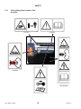
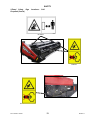
2.3.1
The safety signs appear on the
header/mower conditioner at the locations
shown on pages 7 to 13.
Keep safety signs clean and legible at all
times.
Replace safety signs that are missing or
become illegible.
If original parts on which a safety sign was
installed are replaced, be sure the repair
part also bears the current safety sign.
Safety signs are available from your Dealer
Parts Department.
Safety Sign Installation
a. Be sure the installation area is clean and dry.
b. Decide on the exact location before you remove
the decal backing paper.
c. Remove the smaller portion of the split backing
paper.
d. Place the sign in position, and slowly peel back
the remaining paper, smoothing the sign as it is
applied.
e. Small air pockets can be smoothed out or
pricked with a pin.
ACCIDENTS DISABLE AND KILL.
ACCIDENTS COST.
ACCIDENTS CAN BE AVOIDED.
2.2
SAFETY SIGNS
SIGNAL WORDS
Note the use of the signal words DANGER,
WARNING, and CAUTION with safety
messages. The appropriate signal word for each
message has been selected using the following
guidelines:
DANGER
Indicates an imminently hazardous situation
that, if not avoided, will result in death or
serious injury.
Form 169000 / 169040
6
Revision C
SAFETY
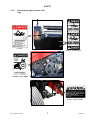
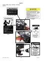
2.3.2
3-Panel Safety Sign Locations: PullType
#170281
#36651 - DRIVELINES
-#142909 - BOTH ENDS
#140311 - BOTH SIDES
Form 169000 / 169040
7
Revision C
SAFETY
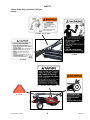
3-Panel Safety Sign Locations: Pull-Type
(cont’d)
#115100 - BOTH SIDES
#109843
#44944
#171029
#30316
Form 169000 / 169040
8
Revision C
SAFETY
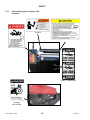
3-Panel Safety Sign Locations: Pull-Type
(cont’d)
#142908 - BACK-SIDE
#44944
#142912
#28403 - BOTH ENDS
#115148
#32738 - BOTH ENDS
Form 169000 / 169040
9
Revision C
SAFETY
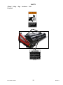
2.3.3
3-Panel Safety Sign Locations: SelfPropelled
#134070
#109843
#170281
#36651 - DRIVELINES
#142909
BOTH ENDS
Form 169000 / 169040
10
Revision C
SAFETY
3-Panel Safety
Propelled
Sign
Locations:
Self-
#32738
#28403
Form 169000 / 169040
11
Revision C
SAFETY
2.3.4
2-Panel Safety Sign Locations: SelfPropelled
#174474
#184372
#184385
#194521
DRIVELINES
#194464
Form 169000 / 169040
12
Revision C
SAFETY
2-Panel Safety Sign
Propelled (Cont’d)
Locations:
Self-
#174632
#184371
#184371 - BOTH ENDS
Form 169000 / 169040
13
Revision C
SAFETY
2.4
GENERAL SAFETY
CAUTION
The following are general farm safety
precautions that should be part of your
operating procedure for all types of
machinery.
•
Protect yourself.
•
When
assembling,
operating
and
servicing machinery, wear all the
protective clothing and personal safety
devices that COULD be necessary for the
job at hand. Don't take chances.
•
You may need:
o
o
o
o
o
o
•
Provide a first-aid kit for use in case of
emergencies.
•
Keep a fire extinguisher on the machine.
Be sure the extinguisher is properly
maintained and be familiar with its proper
use.
•
Keep young children
machinery at all times.
•
Be aware that accidents often happen
when the operator is tired or in a hurry to
get finished. Take the time to consider
the safest way. Never ignore warning
signs of fatigue.
•
Wear close-fitting clothing
and cover long hair. Never
wear dangling items such
as scarves or bracelets.
•
Keep hands, feet, clothing
and hair away from moving
parts. Never attempt to
clear
obstructions
or
objects from a machine while the engine
is running.
•
Keep all shields in place. Never alter or
remove safety equipment. Make sure
driveline
guards
can
rotate
independently of the shaft and can
telescope freely.
a hard hat.
protective
shoes
with
slip
resistant soles.
protective glasses or goggles.
heavy gloves.
wet weather gear.
respirator or filter mask.
away
from
A
B
o
hearing protection. Be aware that
prolonged exposure to loud noise
can cause impairment or loss of
hearing. Wearing a suitable
hearing protective device such as
ear muffs (A) or ear plugs (B)
protects against objectionable or
loud noises.
Form 169000 / 169040
(continued next page)
14
Revision C
SAFETY
GENERAL SAFETY (Cont’d):
•
Use only service and repair parts made
or
approved
by
the
equipment
manufacturer. Substituted parts may not
meet strength, design, or safety
requirements.
•
Do not modify the machine. Unauthorized
modifications may impair the function
and/or safety and affect machine life.
•
Stop engine, and remove key from
ignition before leaving operator's seat for
any reason. A child or even a pet could
engage an idling machine.
•
Keep the area used for servicing
machinery clean and dry. Wet or oily
floors are slippery. Wet spots can be
dangerous when working with electrical
equipment. Be sure all electrical outlets
and tools are properly grounded.
•
Use adequate light for the job at hand.
•
Keep machinery clean. Do not allow oil or
grease to accumulate on service
platforms, ladders or controls. Clean
machines before storage.
•
Never use gasoline, naphtha or any
volatile material for cleaning purposes.
These materials may be toxic and/or
flammable.
•
When storing machinery, cover sharp or
extending components to prevent injury
from accidental contact.
Form 169000 / 169040
15
Revision C
DEFINITIONS
3 DEFINITIONS
The following terms may be used in this manual:
TERM
DEFINITION
API
American Petroleum Institute
APT
Articulating Power Tongue
ASTM
American Society Of Testing And Materials
Cab-Forward
Windrower operation with the operator and cab facing in the direction of travel.
Center Link
A hydraulic cylinder or turnbuckle type link between the header and the machine
that tilts the header.
Engine-Forward
Windrower operation with the operator and engine facing in the direction of travel.
Header or Auger Header
A machine that cuts and conditions hay, and is attached to a windrower.
Mower Conditioner
A machine that cuts and conditions hay, and is pulled by an ag tractor.
PTO
Power Take-Off
rpm
Revolutions Per Minute
SAE
Society Of Automotive Engineers
Self-propelled Windrower
Self-propelled machine consisting of a power unit with a header and conditioner.
Sickle or Knife
A cutting device which uses a reciprocating cutter.
Tractor
Ag type tractor.
Truck
A four-wheel highway/road vehicle weighing no less than 7500 lb (3400 kg).
Windrower
Power unit of a self-propelled auger header.
Form 169000 / 169040
16
Revision C
COMPONENTS
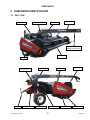
4 COMPONENT IDENTIFICATION
4.1
PULL-TYPE
CARRIER FRAME
STEERING CYLINDER
RESERVOIR
CENTER LINK
ARTICULATING
POWER TONGUE (APT)
LEAN BAR
HEADER
LIFT CYLINDER
LOCK VALVE
FLUFFER
Form 169000 / 169040
SIDE DEFLECTOR
MANUAL CASE
LIFT CYLINDER
HAZARD LIGHT
CONDITIONER
17
DRIVESHIELD
REEL CAM
WOBBLE BOX
Revision C
COMPONENTS
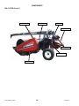
PULL-TYPE (Cont’d)
HEADER DRIVE
HAZARD LIGHT
TAIL-LIGHT
FORMING SHIELD
ADJUSTER BOLTS
FLOAT SPRING
DRIVESHIELD
Form 169000 / 169040
18
Revision C
COMPONENTS
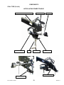
PULL-TYPE (Cont’d)
ARTICULATING POWER TONGUE
STEERING CYLINDER LOCKOUT VALVE
PUMP - 1000 RPM PTO
JACK
CONTROL HOSES
SAFETY CHAIN
DRIVELINE
DRAWBAR HITCH
TOWING ADAPTER
3-POINT HITCH YOKE
Form 169000 / 169040
19
Revision C
COMPONENTS
4.2
SELF-PROPELLED
HYDRAULIC DRIVE
FORMING SHIELD
WINDROWER
HAZARD LIGHT
CUTTERBAR
LEAN BAR
WOBBLE BOX
HEADER DRIVE
CONDITIONER
REEL CAM
HAZARD LIGHT
REEL BAT
DRIVESHIELD
Form 169000 / 169040
SKID SHOE/GAUGE ROLLER
WOBBLE BOX - DOUBLE KNIFE
20
AUGER
Revision C
SPECIFICATIONS
5 SPECIFICATIONS
5.1
PULL-TYPE HEADERS
HEADER SIZE
HEADER MODEL
14 FT
16 FT
A30-S
A30-D
16 ft-3 in.
(4953 mm)
n/a
18 FT
A30-S
A30-D
A30-D
FRAME and STRUCTURE
Width
Length
Height
Transport
26 ft-7 in. (8130 mm)
Field
26 ft-7 in. (8130 mm)
Transport
86 in. (2184 mm)
Field
86 in. (2184 mm)
Approx. Weight [lb (kg)]
7200 (3269)
n/a
7400 (3360)
Pull-Type
Lighting
Two Amber and Two Red Transport Lights
Frame Tube
Lean Bar
Reversing Wrench/Guard Straightening
Tool
8200
(3723)
8000 (3632)
Carrier
Spare Knife Storage
19 ft-3 in.
(5867 mm)
17 ft-9 in. (5410 mm)
Frame Tube
Lean Bar
Stored Inside LH End Sheet
Manual Storage
Frame Mounted Case
WHEELS
Tires
31 x 13.5 - 15 NHS 8 Ply Terra-Rib
Tread Width
150 in. (3810 mm)
Pressure
30 psi (207 kPa)
CUTTERBAR
14 ft-9 in.
(4496 mm)
Effective Cutting Width
16 ft-3 in.
(4953 mm)
17 ft-9 in.
(5410 mm)
4 in. (100 mm) Below Ground to 21 in. (533 mm) Above Ground
Cutting Height
Guard Angle Adjustment
8° - 16°
MAIN DRIVE
Tractor PTO Driven
Gear Pump
540 rpm PTO
2.77 cu. in. (45 cc) With 4:1 Ratio Gearbox
1000 rpm PTO
2.01 cu. in. (33 cc) With 3:1 Ratio Gearbox
HEADER DRIVE
Hydraulic
M44 (44 cc) Motor To Gearbox
SICKLE
Drive Type
Sickle Speed
(Strokes Per Minute)
Belt Driven Heavy Duty (MD) Wobble Box (Enclosed Oil Bath)
Type
Qty
One
Two
One
Two
No Load
1970
1980
1970
1980
Load
1510
1910
Stroke
3 in. (76 mm)
Sections
Bolted Over-Serrated, 9 Serrations/Inch.
Guards
Forged and Double Heat-Treated
Form 169000 / 169040
21
Revision C
SPECIFICATIONS
PULL-TYPE HEADERS (Cont’d)
HEADER SIZE
HEADER MODEL
14 FT
A30-S
16 FT
A30-D
A30-S
18 FT
A30-D
A30-D
AUGER
Drive
Mechanical
2 Belts To Chain
Tube
Size
10 in. (254 mm) O.D
Flighting
20 in. (508 mm) O.D., 0.25 in. (6 mm) thick.
Type
Undershot, Center Feed. Rubber Finger Feed.
Stripper Bars
3 Per Side
20T Sprocket
Speed
(rpm)
19T Sprocket
No Load
265
275
265
275
Load
256
265
256
265
No Load
252
261
252
261
Load
243
252
243
252
Delivery Opening
95.7 in. (2430 mm)
REEL
Drive
Mechanical
Type
2 Belts From Auger To Chain Final Drive
Bats
5 Bat (6 Bat Optional)
Tines
Steel - 0.25 in. (6 mm) Diameter
Tine Bar Bearings
Replaceable Polyethylene
Radius (to tine tip)
20T
Sprocket
Speed
(rpm)
19T
Sprocket
22 in. (540 mm)
20T
Auger
No Load
71
74
71
74
Load
69
71
69
71
19T
Auger
No Load
68
70
68
70
Load
65
68
65
68
20T
Auger
No Load
68
70
68
70
Load
65
68
65
68
19T
Auger
No Load
64
67
64
67
Load
62
64
62
64
CONDITIONER
Drive
Hydraulic
M44 (44cc) Motor To Enclosed Oil-Bath Gearbox
Roll Type
Roll Diameter
Intermeshing Steel Bars
Bars
9.17 in. (233 mm) O.D.
Tube
6.63 in. (168 mm) O.D.
Roll Length
102 in. (2590 mm)
Roll Speed (rpm)
No Load - 824
Swath Width
Unplugging Assist
Forming Shields
Load - 795
36 in. (915 mm) to 92 in. (2340 mm)
Rolls Open As Header Lifts. Rolls Can Open to 4.25 in. (108 mm) During Operation
Header Mounted Adjustable Baffle and Side Deflector System
For 36 in. (915 mm) to 100 in. (2540 mm) Swath Width
OPERATING SPEED
Recommended Cutting
5 mph (8 km/hr)
Recommended Transport
20 mph (30 km/hr)
TRACTOR REQUIREMENTS
Power (minimum)
90 HP (68 kW)
Hydraulics
110 HP (83 kW)
130HP (98 kW)
2000 psi (13,714 kPa)
NOTES: 1. Specifications and design are subject to change without notice or obligation to revise previously sold units.
Form 169000 / 169040
22
Revision C
SPECIFICATIONS
5.2
SELF-PROPELLED HEADERS
HEADER SIZE
HEADER MODEL
14 FT
A30-S
16 FT
A30-D
A40-D
A30-S
A30-D
18 FT
A40-D
A30-D
A40-D
FRAME and STRUCTURE
Width
16 ft-3 in. (4953 mm)
Weight [lb (kg)]
n/a
17 ft-9 in. (5410 mm)
5680
(2579)
n/a
n/a
n/a
19 ft-3 in. (5867 mm)
5850
(2656)
Carrier
MacDon M Series Self-Propelled Windrowers
Lighting
Two Amber Transport Lights
Frame
Tube
Spare Knife Storage
Frame
Tube
Lean Bar
Reversing Wrench/Guard
Straightening Tool
6020
(2733)
n/a
Lean Bar
Lean Bar
Stored Inside LH End Sheet
Manual Storage
Windrower Cab
CUTTERBAR
14 ft-9 in. (4496 mm)
Effective Cutting Width
16 ft-3 in. (4953 mm)
17 ft-9 in. (5410 mm)
5.9 in. (150 mm) Below Ground to 35.4 in. (900 mm) Above Ground
Cutting Height
Guard Angle Adjustment
7° - 17.5°
HEADER DRIVE
A30
Hydraulic From Windrower Pump to One Piston Motor
A40
Hydraulic From Windrower Pump to One Piston Motor and Two Gear Motors
SICKLE
Belt Driven Heavy Duty
(MD) Wobble Box
(Enclosed Oil Bath)
Belt Type
Qty
Sickle Speed (Strokes Per Minute)
V
Timing
V
Timing
One
Two
One
Two
1540
1450 - 1950
1540
1450 - 1950
Stroke
3 in. (76 mm)
Sections
Bolted Over-Serrated, 14 Serrations/Inch. (9 Serrations/Inch Optional)
Guards
Forged And Double Heat-Treated
AUGER
3
Drive
Mechanical
Max Speed (rpm)
--
15.9 in
(261 cc)
/rev
--
15.9 in
(261 cc)
/rev
2 Belts To Chain
---
2 Belts To Chain
---
2 Belts
To Chain
---
260
270
19T Sprocket
250
260
Type
230- 320*
Tube
Flighting
3
15.9 in
(261 cc)
/rev
20T Sprocket
Size
3
--
Hydraulic Direct
Mounted Motor
260
270
250
260
230320*
270
260
230320*
10 in. (254 mm) O.D.
20 in. (508 mm) O.D., 0.25 in. (6 mm) thick.
Undershot, Center Feed. Rubber Finger Feed
Stripper Bars
3 Per Side
Delivery Opening
95.7 in. (2430 mm)
* Max Speed on M100 Windrower
Form 169000 / 169040
23
Revision C
SPECIFICATIONS
SELF-PROPELLED HEADERS (Cont’d)
14 FT
HEADER SIZE
HEADER MODEL
A30-S
A30-D
16 FT
A40-D
A30-S
18 FT
A30-D
A40-D
A30-D
A40-D
--
14.2 in
(232 cc)
/rev
REEL
3
Hydraulic Direct
Mounted Motor
3
--
14.2 in
(232 cc)
/rev
--
14.2 in
(232 cc)
/rev
2 Belts/Chain Final
Drive
---
2 Belts/Chain Final
Drive
---
5 Bat
(6 Bat Opt)
6 Bat
(7 Opt)
5 Bat
(6 Opt)
6 Bat
(7 Opt)
Drive
Mechanical From
Auger
Type
Tines
3
2 Belts/
Chain
Final
Drive
5 Bat
(6 Opt)
-6 Bat
(7 Opt)
Steel - 0.25 in. (6 mm) Dia.
Replaceable
Polyethylene
Tine Bar Bearings
Greasable
Ball
Radius (to tine tip)
22T
Sprocket
Max Speed
(rpm)
19T
Sprocket
Replaceable
Polyethylene
Greasable
Ball
Replaceable
Greasable
PolyBall
ethylene
22 in. (540 mm)
22T
Auger
19T
Auger
22T
Auger
19T
Auger
77
77
73
67
67
15 - 85*
58
69
15 - 85*
15 - 85*
67
69
58
66
CONDITIONER
Drive
M44 (44cc) Motor To Enclosed Oil-Bath Gearbox
Hydraulic
Roll Type
Roll Diameter
Intermeshing Steel Bars
Bars
9.17 in. (233 mm) O.D.
Tube
6.63 in. (168 mm) O.D.
Roll Length
Roll Speed (rpm)
102 in. (2590 mm)
810
601 - 810
Unplugging Assist
Forming Shields
810
601 810
810
601 - 810
Reversing Flow To Hydraulic Motors
Windrower Mounted Side Deflector System For
36 in. (915 mm) to 100 in. (2540 mm) Swath Width
OPERATING SPEED
Recommended Cutting
5 mph (8 km/hr)
* 50 - 85 rpm for M100.
NOTES: 1. Specifications and design are subject to change without notice or obligation to revise previously sold units.
Form 169000 / 169040
24
Revision C
OPERATION
If you do not have a tractor/windrower
manual, get one from your Dealer and
read it thoroughly.
6 OPERATION
•
Never
attempt
to
start
the
tractor/windrower engine or operate the
machine except from the Operator’s seat.
•
Check the operation of all controls in a
safe clear area before starting work.
It is your responsibility to read and
understand this manual completely
before operating the header/mower
conditioner. Contact your Dealer if an
instruction is not clear to you.
•
Do not allow riders on tractor/windrower
or mower conditioner.
•
Never start or move the machine until
you are sure all bystanders have cleared
the area.
•
Follow all safety messages in the manual
and on safety signs on the machine.
•
Avoid travelling over loose fill, rocks,
ditches or holes.
•
Remember that YOU are the key to
safety. Good safety practices protect you
and the people around you.
•
Drive
slowly
doorways.
•
•
Before allowing anyone to operate the
header/mower conditioner, for however
short a time or distance, make sure they
have been instructed in its safe and
proper use.
If cutting ditch banks, use extreme
caution. If the header/mower conditioner
hits an obstruction, the front of the
tractor will usually swerve towards the
ditch.
•
•
Review the manual and all safety related
items with all operators annually.
•
Be alert for other operators not using
recommended
procedures
or
not
following safety precautions. Correct
these mistakes immediately, before an
accident occurs.
When working on inclines, travel uphill or
downhill when possible. Be sure to keep
tractor transmission in gear when
travelling downhill.
•
Never attempt to get on or off a moving
tractor/windrower.
•
Do not get off the tractor/windrower while
the machine is in operation.
•
Stop tractor/windrower engine and
remove key before adjusting or removing
plugged material from the machine. A
child or even a pet could engage the
drive.
•
Check for excessive vibration and
unusual noises. If there is any indication
of trouble, shut down and inspect the
machine. Follow proper shutdown
procedure:
o engage tractor/windrower brake.
o disengage PTO.
o turn off engine, and remove key
o wait for all movement to stop
o dismount and engage cylinder
stops before inspecting raised
machine.
•
Operate only in daylight or good artificial
light.
6.1
OWNER/OPERATOR
RESPONSIBILITIES
CAUTION
•
•
Do not modify the machine. Unauthorized
modifications may impair the function
and/or safety and affect machine life.
•
The safety information given in this
manual does not replace safety codes,
insurance needs, or laws governing your
area. Be sure your machine meets the
standards set by these regulations.
•
6.2
Ensure that the tractor is properly
equipped to safely operate the mower
conditioner. This may include adding
ballast according to Tractor Operator’s
Manual requirements for attachments of
this size and mass.
OPERATIONAL SAFETY
CAUTION
•
Follow all safety and operational
instructions given in your Operator's
Manual.
Form 169000 / 169040
25
through
gates
and
Revision C
OPERATION
6.3
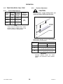
6.3.2
TRACTOR SETUP: PULL-TYPE
6.3.1
Drawbar Adjustment
CAUTION
Tractor Requirements
HEADER
WIDTH
14 FT
16 FT
18 FT
90
(68)
110
(83)
MINIMUM
DRAWBAR
CAPACITY
LBF (N)
1400
(6227)
1450
(6449)
130
(98)
1500
(6672)
MINIMUM
POWER
HP (KW)
MINIMUM
HYDRAULICS
psi (MPA)
Shut off tractor, engage parking brake, and
remove key before working around hitch.
PTO
2000
(13.7)
X
NOTE
Tractor must be equipped with a seven
terminal outlet to supply power to the
mower conditioner's warning lights.
TRACTOR
DRAWBAR
Y
GROUND
Z
Adjust tractor drawbar to meet ASAE Standard
specifications as listed below:
DIMENSION
X
1000 RPM PTO
1.37 IN. DIA.
1.75 IN. DIA.
16 in. (406 mm)
20 in. (508 mm)
Y
6 - 12 in. (152 - 305 mm)
8 in. (203 mm) Recommended
Z
13 - 17 in. (330 - 432 mm)
16 in. (406 mm) Recommended
IMPORTANT
Improper drawbar length can cause
vibration and premature pump gearbox
failure.
Form 169000 / 169040
26
Revision C
OPERATION
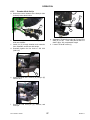
6.3.3
Drawbar Hitch Set-Up
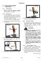
a. Secure the tractor drawbar so the hitch-pin hole
is directly below the driveline.
G
J
A
B
H
C
g. Assemble PTO driveline male half (G) onto PTO
shaft (H) on APT. Push male half so that PTO
shaft is at its “fully compressed” length.
h. Locate PTO shaft in hook (J).
b. Loosen bolts (B) on extension assembly (A), and
slide onto drawbar.
c. Install pin (C) through drawbar and extension
from underside, and secure with hairpin.
d. Gradually tighten the four bolts to 265 ft·lbf
(359 N·m).
E
D
e. Attach the swivel APT member (D) with pin (E)
onto the APT.
F
f.
Secure pin with clevis pin (F), washers, and
cotter pin.
Form 169000 / 169040
27
Revision C
OPERATION
6.3.4
3 Point Hitch (Cat. II, III, or IIIN) SetUp
F
C
NOTE
Bushings (F) on pins can be removed to
suit hole size in tractor hitch arms.
B
A
G
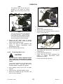
a. Attach the 3 point hitch yoke (A) to the APT with
pin (B).
The installation is similar to that
described in the previous section.
b. Secure pin (B) with clevis pin (C), washers, and
cotter pin.
c. The arms (D) on APT yoke can be set up to suit
the tractor hitch arms:
J
H
d. Assemble PTO driveline male half (G) onto PTO
shaft (H) on APT. Push male half so that PTO
shaft is at its “fully compressed” length.
e. Locate PTO shaft in hook (J).
D
CATEGORY II or IIIN
E
CATEGORY III
1. Remove pins (E) from arms.
2. Remove arms (D) from APT yoke.
3. Re-install arms on opposite ends of yoke as
shown.
4. Re-install pins (E) in arms.
Form 169000 / 169040
28
Revision C
OPERATION
6.4
E
MOWER CONDITIONER / TRACTOR
HOOKUP: PULL-TYPE
F
CAUTION
Shut off tractor, engage parking brake, and
remove key before working around hitch.
CAUTION
G
Never attach mower conditioner to tractor
rear axle or three-point hitch arms.
6.4.1
H
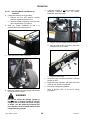
e. Attach driveline (E) to tractor PTO shaft as
follows:
1. Position driveline onto tractor PTO shaft (F).
2. Pull back collar on driveshaft, and push
driveshaft until it locks. Release collar.
f. Route safety chain from mower conditioner
through chain support (G), around drawbar
support and lock the hook (H) on chain.
Drawbar Hook-Up
A
IMPORTANT
Adjust chain length to remove all slack
except what is needed for turns.
a. Remove pin (A).
J
A
D
D
B
C
J
b. Position tractor to align drawbar extension (B)
with arm (C) on mower conditioner.
c. Lower jack (D) to engage arm (C) on drawbar
extension (B).
d. Install hitch-pin (A), and secure with hairpin.
IMPORTANT
If the tractor has a three-point hitch, lower
the lower links as low as possible to
prevent damage to (APT).
Form 169000 / 169040
g. Raise jack (D), pull pin (J) and move jack to
storage position on side of APT.
h. Secure jack with pin (J).
i. Proceed to Step 6.4.3 Hydraulic Connections.
29
Revision C
OPERATION
6.4.2
3 Point Hitch (Cat. II, III, or IIIN)
Hook-Up
CAUTION
DRIVELINE SHAFT SIZE
DISTANCE ‘X’
1.375 in. (34 mm)
14 in. (356 mm)
1.75 in. (43 mm)
17 in. (432 mm)
Shut off tractor, engage parking brake, and
remove key before working around hitch.
G
A
F
e. Change locations of pins (F) in APT arms to hole
(G) to locate implement closer to tractor (if
necessary).
C
B
J
CAT. II and IIIN CONFIGURATION
a. Position tractor, and align tractor hitch arms (A)
with mower conditioner arms (B). Use the jack
to adjust height of mower conditioner.
b. Secure arms with lynch pins (C).
c. Install anti-sway bars on tractor hitch to stabilize
lateral movement of hitch arms (A). Refer to
your tractor Operator’s Manual.
TRACTOR AXLE
H
MOWER CONDITIONER
f.
D
X
Position driveshaft (H) onto tractor PTO shaft.
Driveline should be approximately level.
g. Pull back collar on driveshaft, and push
driveshaft until it locks. Release collar.
h. Rotate driveline storage hook (J) to “upward”
position.
(continued next page)
E
d. Check distance ‘X’ between tractor PTO shaft
(D) and implement input shaft (E) (without the
front half of the driveline attached).
IMPORTANT
The distance ‘X’ must not exceed the
specified values in next column.
Otherwise, the driveline can vibrate and
cause premature failure of the driveline or
pump gearbox.
Form 169000 / 169040
30
Revision C
OPERATION
K
L
Q
P
i.
Attach down-stop chains (K) to pin (L) on tractor.
k.
CAUTION
Raise jack (P), pull pin (Q), and move jack to
storage position on side of APT.
The downstop chains limit the downward
travel of the 3-point hitch lifting arms to
prevent damaging the PTO driveline on the
mower-conditioner.
Ensure chains are
attached when operating the mowerconditioner.
j.
Q
Adjust chain length as required by relocating
end link at tractor end of chain as follows:
O
l.
Secure jack with pin (Q).
N
M
1. Remove cotter pin and clevis pin (M) to
disconnect open link (N) and end link (O).
2. Relocate open link (N) to new location on
chain, and re-attach to end link (O) with
clevis pin (M). Chains do not need to be
tight.
3. Secure clevis pin with cotter pin.
Form 169000 / 169040
31
Revision C
OPERATION
6.4.3
b. Connect two steering cylinder hoses (A) as
follows:
Hydraulic Connections
WARNING
Do not use remote hydraulic system
pressures over 3000 psi (20684 kPa). Check
your tractor Operator’s Manual for remote
system pressure.
B
c.
A
CONTROL
LEVER
POSITION
CYLINDER
MOVEMENT
MOWERCONDITIONER
DIRECTION
Forward
Extend
Right
Backward
Retract
Left
Connect one lift cylinder hose (B) as follows:
CONTROL
LEVER
POSITION
CYLINDER
MOVEMENT
HEADER
MOVEMENT
Forward
Retract
Lower
Backward
Extend
Raise
d. Connect two header tilt cylinder hoses (C) as
follows: (Not required with mechanical center
link).
C
SYSTEM
HOSE
Steering
A (2 Hoses)
TRACTOR
HYDRAULICS
Control 1
Lift
B (1 Hose)
Control 2
Header Tilt
C (2 Hoses)
Control 3
CONTROL
LEVER
POSITION
CYLINDER
MOVEMENT
HEADER
MOVEMENT
Forward
Retract
Lower
Backward
Extend
Raise
e. Connect the mower-conditioner wiring harness
connector (D) to tractor. The connector is
designed to fit tractors equipped with a round
7-pin receptacle (SAE J560).
NOTE
Arrows cut into plate indicate system for
hoses. LIFT
STEERING
E
G
F
IMPORTANT
Older model tractors will have Pin #4 (F)
energized as an accessory circuit. The
mower conditioner uses this pin position
(G) for brake lights. Check that Pin #4 in
the tractor receptacle is not constantly
energized – see tractor Operator’s
Manual, and remove the appropriate fuse
if required.
a. Ensure hoses are routed through guide (E) to
provide proper hose arc as shown.
A
C
D
B
Form 169000 / 169040
32
Revision C
OPERATION
6.5
MOWER CONDITIONER / TRACTOR
UNHOOK: PULL-TYPE
CAUTION
To prevent accidental movement of tractor,
shut off engine, engage parking brake, and
remove key.
C
To maintain stability, always lower the
machine
completely.
Block
mower
conditioner wheels before detaching from
tractor.
6.5.1
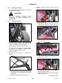
f. Rotate hook (C) to “lower” position.
g. Pull back collar on driveline (B), and slide
coupler off tractor PTO shaft, and position
driveline in hook.
Drawbar Hitch Unhook
a. Park machine on flat level surface with hitch at
an angle to tractor drawbar (to facilitate pump
detachment).
b. Lower header onto blocks or leave header
raised. Engage lift cylinder lock-out valves if
leaving in raised position.
c. Move remote cylinder control valve lever back
and forth to relieve stored hydraulic pressure.
D
E
D
d. Disconnect hydraulic hoses and electrical
harness. Store hose ends in holes at front of
APT as shown.
E
A
h. Pull pin (D) securing jack (E), and move to
“working” position at front of APT. Secure jack
with pin (D).
i. Lower jack to take weight off tractor drawbar.
B
NOTE
If ground is soft, place a block under the
jack.
e. Remove pin (A).
(continued next page)
Form 169000 / 169040
33
Revision C
OPERATION
F
j.
k.
l.
Remove chain lock (F), and unhook safety chain
from tractor. Wrap chain around APT for
storage.
Lower jack to raise APT clear of drawbar.
Slowly drive tractor away from mower
conditioner.
A
m. Replace hitch pin (A), and secure with hairpin.
Form 169000 / 169040
34
Revision C
OPERATION
6.5.2
3-Point Hitch Unhook
C
a. Park machine on flat level surface.
b. Lower header onto blocks or leave header
raised. Engage lift cylinder lock-out valves if
leaving in raised position.
c. If necessary, raise 3-point hitch arms to release
tension on downstop chains.
D
CAUTION
To prevent accidental movement of tractor,
shut off engine, engage parking brake, and
remove key.
h. Pull pin (C) securing jack (D) to APT, and move
to “working” position. Secure jack with pin (C).
To maintain stability, always lower the
machine
completely.
Block
mower
conditioner wheels before detaching from
tractor.
E
d. Shut off engine, and remove key.
e. Move remote cylinder control valve lever back
and forth to relieve stored hydraulic pressure.
F
C
D
i.
j.
k.
f.
Rotate hook (F) to “lower” position.
Pull back collar on driveline (E), and slide
coupler off tractor PTO shaft. Place driveline in
hook.
Lower jack (D) to take weight off hitch arms.
Disconnect hydraulic hoses and electrical
harness. Store hose ends in holes at front of
APT as shown.
H
A
B
G
l.
Remove lynch pins (G), and swing hitch
arms (H) clear of APT.
m. Slowly drive tractor away from mower
conditioner.
g. Remove pin (A), and remove down-stop chains
(B) from tractor, and store on APT yoke.
Form 169000 / 169040
35
Revision C
OPERATION
6.6
HEADER ATTACHMENT: SELFPROPELLED
Refer to your Self-Propelled Windrower
Operator’s
Manual
for
procedures
for
mechanically attaching the auger header to the
self-propelled windrower.
Refer to the following procedures for electrical
and hydraulic connections. The header drive
hydraulic hoses and electrical harness are
located on the LH cab-forward side of the
windrower.
6.6.1
A30-S, A30-D
6.6.1.1
M100, M150, M200
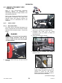
C
E
D
The M100, M150, and M200 Windrowers are
factory equipped with A30-S and A30-D header
hydraulics and electrical harness. Proceed as
follows:
b. Remove the cap (C) from electrical connector,
and remove connector from support bracket.
c. Disengage and rotate lever (D) counter
clockwise to “fully up” position to release the
hose bundle (E).
d. Move hose bundle (E) to header.
DANGER
Stop engine, and remove key from ignition
before leaving Operator's seat for any
reason. A child or even a pet could engage
an idling machine.
E
D
B
e. Rotate lever (D) clockwise, and engage in
bracket to store.
A
NOT USED
a. Disengage rubber latch (A), and open driveline
shield (B).
IMPORTANT
If the hose bundle contains four hoses
(draper header operation), only three are
required to power the A30 header.
Ensure loose hose is properly secured to
avoid contact with the drivelines.
(continued next page)
Form 169000 / 169040
36
Revision C
OPERATION
6.6.1.2
M205
E
F
H
G
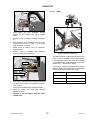
f.
Route hoses (E) from windrower through
support (F) and access hole (G) in header
frame.
g. Remove cover on header electrical receptacle
(H).
h. Push connector onto receptacle, and turn collar
on connector to lock it in place. Try to rotate
collar to ensure it is locked.
i. Attach cover to mating cover on windrower
wiring harness.
j. Remove caps (if installed) from hydraulic
couplers, and clean if necessary.
AUGER HEADER HYDRAULICS
The M205 must be equipped with an auger drive
basic kit and a completion kit as shown above.
If it is equipped, connect the hoses to the header
in accordance with the procedure in the previous
Section 6.6.1.1 M100, M150, M200.
RETURN
If necessary, obtain the following kits from your
MacDon dealer and install them in accordance
with the instructions supplied with the kit.
CASE DRAIN
HEADER DRIVE
k.
Push hose connectors onto mating receptacles
(as shown) until collars on receptacles snap into
“lock” position.
l. Close driveline shield before engaging header.
m. Check to ensure that hoses and electrical
harness clear tire.
n. Proceed to 6.6.3 Configure Reverser Valve
Jumper Hose.
Form 169000 / 169040
37
Kit Description
Kit Number
Base Kit
B5491
Completion
B5492
Coupler
B5497
Revision C
OPERATION
6.6.2
A40-D
CAUTION
To prevent accidental movement of
windrower, place all controls in NEUTRAL or
in PARK, engage park brake (if applicable),
shut off engine, and remove key.
C
E
6.6.2.1
M100
D
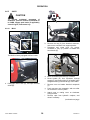
b. Remove the cap (C) from electrical connector,
and remove connector from support bracket.
c. Disengage and rotate lever (D) counter
clockwise to “fully up” position to release the
hose bundle (E).
The M100 is factory equipped with four hoses.
E
F
J
G
H
B
A
d. Move hose/electrical bundle (E) to header.
e. Route bundle (E) from windrower through
support (F) and access hole (G) in header frame
alongside existing hose bundle (H) from header.
f. Remove cover on header electrical receptacle
(J).
g. Push connector onto receptacle, and turn collar
on connector to lock it in place.
h. Attach cover to mating cover on windrower
wiring harness.
i. Remove caps from hydraulic couplers, and
clean if necessary.
(continued next page)
a. Disengage rubber latch (A), and open driveline
shield (B).
Form 169000 / 169040
38
Revision C
OPERATION
REEL and AUGER
PRESSURE
KNIFE and
CONDITIONER
RETURN
CASE DRAIN
KNIFE and
CONDITIONER
PRESSURE
STANDARD HEADER
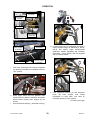
m. If valve blocks are not configured (as shown),
install required fittings as described in “A30-S,
A30-D and A40-D Auger Self-Propelled
Windrower Header Unloading and Assembly
Instructions - Form 169078” that was supplied
with your A40-D header.
AUGER and REEL
PRESSURE
KNIFE RETURN
(MALE FITTING
AT HEADER)
KNIFE PRESSURE
(FEMALE FITTING
AT HEADER)
CASE DRAIN
B
GRASS SEED HEADER
j.
Push hose connectors onto mating receptacles
(as shown) until collars on receptacles snap into
“lock” position.
A
D
H
B
K
k.
l.
L
n. Push auger/reel pressure (A) and auger/reel
return (B) hose couplers onto mating
receptacles on valve block, until collar on
receptacle snaps into “lock” position.
(continued next page)
Route auger return and reel pressure hose
bundle (H) from header to windrower, and locate
bundle above existing hose support (K) (as
shown).
Secure with three straps (L), and lower lever (D).
Form 169000 / 169040
A
39
Revision C
OPERATION
o. Open header LH driveshield.
p. Check hose routing at the reel motor. The hose
routing depends on which windrower model the
header is being attached to. The header is
factory assembled for M150 and M200
windrowers.
D
C
E
FACTORY CONFIGURATION
q. Change hoses as follows if header is being
mounted on a M100 windrower:
1. Disconnect hose (C) at tee (E).
2. Disconnect hose (D) at reel motor.
3. Disconnect tee (E) at motor lower port and
relocate to upper port.
D
E
C
M100/M205 CONFIGURATION
4. Connect hose (D) to tee (E).
5. Connect hose (C) to motor lower port.
Form 169000 / 169040
40
Revision C
OPERATION
6.6.2.2
M150
CAUTION
To prevent accidental movement of
windrower, place all controls in NEUTRAL or
in PARK, engage park brake (if applicable),
shut off engine, and remove key.
C
E
D
b. Remove the cap (C) from electrical connector,
and remove connector from support bracket.
c. Disengage and rotate lever (D) counter
clockwise to “fully up” position to release the
hose bundle (E).
The M150 is factory equipped with four hoses.
E
F
J
G
B
H
A
d. Move hose/electrical bundle (E) to header.
e. Route bundle (E) from windrower through
support (F) and access hole (G) in header frame
alongside existing hose bundle (H) from header.
f. Remove cover on header electrical receptacle
(J).
g. Push connector onto receptacle, and turn collar
on connector to lock it in place.
h. Attach cover to mating cover on windrower
wiring harness.
i. Remove caps from hydraulic couplers, and
clean if necessary.
(continued next page)
a. Disengage rubber latch (A), and open driveline
shield (B).
Form 169000 / 169040
41
Revision C
OPERATION
REEL and AUGER
PRESSURE
KNIFE and
CONDITIONER
RETURN
A
B
CASE DRAIN
KNIFE and
CONDITIONER
PRESSURE
AUGER/REEL RETURN
STANDARD HEADER
AUGER
PRESSURE
B
A
AUGER and REEL
PRESSURE
KNIFE RETURN
(MALE FITTING
AT HEADER)
M150 - WITHOUT REVERSER VALVE
AUGER/REEL RETURN
KNIFE PRESSURE
(FEMALE FITTING
AT HEADER)
CASE DRAIN
AUGER
PRESSURE
GRASS SEED HEADER
j.
D
K
l.
A
Push hose connectors onto mating receptacles
(as shown) until collars on receptacles snap into
“lock” position.
H
k.
B
M150 - WITH REVERSER VALVE
m. If valve blocks are not configured as shown
above, install required fittings as described in
“A30-S, A30-D and A40-D Auger Self-Propelled
Windrower Header Unloading and Assembly
Instructions - Form 169078” that was supplied
with your A40-D header.
n. Push auger pressure (A) and auger/reel return
(B) hose couplers onto mating receptacles on
valve block until collar on receptacle snaps into
“lock” position.
o. Proceed to 6.6.3. Configure Reverser Valve
Jumper Hose.
L
Route auger return and reel pressure hose
bundle (H) from header to windrower, and locate
bundle above existing hose support (K) (as
shown).
Secure with three straps (L) and lower lever (D).
Form 169000 / 169040
42
Revision C
OPERATION
6.6.2.3
M200
CAUTION
To prevent accidental movement of
windrower, place all controls in NEUTRAL or
in PARK, engage park brake (if applicable),
shut off engine, and remove key.
C
E
D
b. Remove the cap (C) from electrical connector,
and remove connector from support bracket.
c. Disengage and rotate lever (D) counter
clockwise to “fully up” position to release the
hose bundle (E).
The Windrower requires four hoses to run an
A40-D header. If required, configure the M200
to run an A40-D auger header by installing Kit
B4651. The Kit includes the additional hose,
hardware, and installation instructions.
E
F
J
G
H
B
d. Move hose/electrical bundle (E) to header.
e. Route bundle (E) from windrower through
support (F) and access hole (G) in header frame
alongside existing hose bundle (H) from header.
f. Remove cover on header electrical receptacle
(J).
g. Push connector onto receptacle, and turn collar
on connector to lock it in place.
h. Attach cover to mating cover on windrower
wiring harness.
i. Remove caps from hydraulic couplers, and
clean if necessary.
(continued next page)
A
a. Disengage rubber latch (A), and open driveline
shield (B).
Form 169000 / 169040
43
Revision C
OPERATION
REEL and AUGER
PRESSURE
KNIFE and
CONDITIONER
RETURN
B
A
CASE DRAIN
AUGER/REEL RETURN
KNIFE and
CONDITIONER
PRESSURE
AUGER
PRESSURE
STANDARD HEADER
B
AUGER and REEL
PRESSURE
KNIFE RETURN
(MALE FITTING
AT HEADER)
A
M200 - WITH REVERSER VALVE
KNIFE PRESSURE
(FEMALE FITTING
AT HEADER)
CASE DRAIN
AUGER
PRESSURE
AUGER/REEL RETURN
B
GRASS SEED HEADER
j.
D
H
M200 - WITHOUT REVERSER VALVE
K
k.
l.
A
Push hose connectors onto mating receptacles
(as shown) until collars on receptacles snap into
“lock” position.
m. If valve blocks are not configured as shown
above, install required fittings as described in
“A30-S, A30-D and A40-D Auger Self-Propelled
Windrower Header Unloading and Assembly
Instructions - Form 169078” that was supplied
with your A40-D header.
n. Push auger pressure (A) and auger/reel return
(B) hose couplers onto mating receptacles on
valve block until collar on receptacle snaps into
“lock” position.
o. Proceed to 6.6.3 Configure Reverser Valve
Jumper Hose.
L
Route auger return and reel pressure hose
bundle (H) from header to windrower, and locate
bundle above existing hose support (K) (as
shown).
Secure with three straps (L) and lower lever (D).
Form 169000 / 169040
44
Revision C
OPERATION
6.6.2.4
M205
CAUTION
To prevent accidental movement of
windrower, place all controls in NEUTRAL or
in PARK, engage park brake (if applicable),
shut off engine, and remove key.
B
A
a. Disengage rubber latch (A), and open driveline
shield (B).
C
E
D
AUGER HEADER HYDRAULICS
The M205 must be equipped with an auger drive
basic kit and a completion kit as shown above.
If necessary, obtain the following kits from your
MacDon dealer, and install them in accordance
with the instructions supplied with the kit.
Kit Description
Kit Number
Base Kit
B5491
Completion
B5492
Coupler
B5497
Form 169000 / 169040
b. Remove the cap (C) from electrical connector,
and remove connector from support bracket.
c. Disengage and rotate lever (D) counter
clockwise to “fully up” position to release the
hose bundle (E).
d. Move hose/electrical bundle (E) to header.
(continued next page)
45
Revision C
OPERATION
j.
E
F
G
J
Push hose connectors onto mating receptacles
(as shown) until collars on receptacles snap into
“lock” position.
D
H
H
K
e. Route bundle (E) from windrower through
support (F) and access hole (G) in header frame
alongside existing hose bundle (H) from header.
f. Remove cover on header electrical receptacle
(J).
g. Push connector onto receptacle, and turn collar
on connector to lock it in place.
h. Attach cover to mating cover on windrower
wiring harness.
KNIFE and
CONDITIONER
RETURN
k.
l.
L
Route auger return and reel pressure hose
bundle (H) from header to windrower, and locate
bundle above existing hose support (K) (as
shown).
Secure with three straps (L) and lower lever (D).
REEL and AUGER
PRESSURE
B
A
CASE DRAIN
KNIFE and
CONDITIONER
PRESSURE
m. Push auger/reel pressure (A) and auger/reel
return (B) hose couplers onto mating
receptacles on valve block until collar on
receptacle snaps into “lock” position.
n. Re-route header drive hoses. Refer to Section
6.6.2.1 M100, step q.
STANDARD HEADER
KNIFE RETURN
(MALE FITTING
AT HEADER)
CASE DRAIN
AUGER and REEL
PRESSURE
KNIFE PRESSURE
(FEMALE FITTING
AT HEADER)
GRASS SEED HEADER
i.
Remove caps from hydraulic couplers, and
clean if necessary.
Form 169000 / 169040
46
Revision C
OPERATION
6.6.3
IMPORTANT
Configure Reverser Valve Jumper
Hose
If a reverser valve block (A) has been
installed, the jumper hose (B) must be
routed as shown opposite.
Do not
operate the headers unless hose is
routed as shown.
An optional reverser valve block to reverse the
header drive in the event of plugging, may have
been installed on the M150 and M200
windrowers. A jumper hose on this valve block
has a specific routing for each model of auger
header. Check the routing of the jumper hose
as follows, and change as required:
A
a. Move LH windrower platform to “open” position
to expose hydraulic valve blocks.
C2
C
B
A
b. To route hose (B) from A40-D position to
A30-S, A30-D position:
1. Disconnect jumper hose (B) at header drive
valve block port C2 fitting.
2. Rotate 90° fitting (C) under reverser valve
block (A) so that it points “aft”.
A
B
R4
B
HOSE (B) POSITION - A40-D
M200 SHOWN - M150 SIMILAR
A
B
C
3. Remove cap from 90° fitting in port R4 on
top of reverser block.
4. Connect jumper hose (B) onto 90° fitting in
port R4.
5. Install cap removed in step 3. onto port C2
fitting.
(continued next page)
HOSE (B) POSITION - A30-S, A30-D
M150 SHOWN - M200 SIMILAR
Form 169000 / 169040
47
Revision C
OPERATION
c.
To route hose (B) from A30-S, A30-D position
to A40-D position:
R4
A
B
C
1. Disconnect jumper hose (B) at 90° fitting in
port R4.
A
C2
D
B
2. Rotate 90° fitting (C) under reverser valve
block (A) so that hose can be routed to port
C2 on header drive valve block.
3. Remove cap from port C2 fitting on header
drive valve block.
4. Connect jumper hose (B) to port C2 fitting
on header drive valve block.
5. Install cap removed in step 3. onto 90° fitting
in port R4 on reverser valve block (A).
d. Move LH maintenance platform to normal
operating position.
Form 169000 / 169040
48
Revision C
OPERATION
6.7
c.
HEADER DETACHMENT: SELFPROPELLED
Disconnect hoses from hydraulic motor as
follows:
CAUTION
D
C
To prevent accidental movement of
windrower, shut off engine, engage parking
brake, and remove key.
6.7.1
A30-S, A30-D Detachment
1. Line up slot (C) in collar with pin (D) on
connector.
2. Push collar toward pin, and pull connector to
disengage.
3. Install caps on connectors and hose ends (if
equipped).
B
A
G
a. Disengage rubber latch (A), and lift driveline
shield (B) to “open” position.
E
F
ELECTRICAL
RETURN
CASE DRAIN
d. Move hose bundle (E) from header, and locate
on windrower LH side with hose ends in support
(F) and under lever (G).
e. Rotate lever (G) clockwise, and push to engage
bracket.
f. Locate electrical harness through support (F),
and attach cap to electrical connector.
g. Close header driveline shield, and move
windrower platform to “closed” position.
h. Check to ensure hoses and electrical harness
clear tire.
i. Detach header from windrower. Refer to your
Self-Propelled Windrower Operator’s Manual for
procedures for mechanically detaching the
header from the self-propelled windrower.
HEADER DRIVE
b. Disconnect electrical connector by turning collar
counter clockwise, and pulling connector to
disengage.
Form 169000 / 169040
49
Revision C
OPERATION
6.7.2
b. Disconnect the two hydraulic hoses (A) and (B)
or (C) and (D) from windrower valve(s).
A40-D Detachment
CAUTION
E
G
To prevent accidental movement of
windrower, place all controls in NEUTRAL or
in PARK, engage park brake (if applicable),
shut off engine, and remove key.
a. Move LH cab-forward platform to rear of
windrower.
F
c. Raise lever (E), and undo Velcro straps (F).
d. Move hose bundle (G) to store on header
walkway.
e. Install caps on connectors and hose ends if
equipped.
B
A
M150 WITHOUT REVERSER VALVE
M200 SIMILAR
B
A
STANDARD HEADER
M150 WITH REVERSER VALVE
M200 SIMILAR
C
D
GRASS SEED HEADER
f.
At the header, disconnect electrical connector by
turning collar counter clockwise, and pulling
connector to disengage.
g. Disconnect hoses from hydraulic motor, and
auger and reel pressure hose.
(continued next page)
M100
Form 169000 / 169040
50
Revision C
OPERATION
E
H
J
h. Move hose bundle (H) from header, and locate
on windrower LH side with hose ends in support
(J) and under lever (E).
i. Rotate lever (E) clockwise, and push to engage
bracket.
j. Locate electrical harness through support (J),
and attach cap to electrical connector.
k. Close driveline shield, and move windrower
platform to “closed” position.
l. Check to ensure hoses and electrical harness
clear tire.
m. Detach header from windrower. Refer to your
Self-Propelled Windrower Operator’s Manual for
procedures for mechanically detaching the
header from the self-propelled windrower.
Form 169000 / 169040
51
Revision C
OPERATION
6.8
TRANSPORTING MOWER
CONDITIONER
6.8.1
DIRECTION OF TRAVEL
Self-Propelled
B
Refer to your Self-Propelled Windrower
Operator’s Manual for transporting headers
when attached to the Windrower.
6.8.1.1
AMBER
Amber Lights
The two hazard light fixtures are fitted with
reversible amber and red reflector assemblies to
accommodate cab-forward and engine-forward
operation (M150, M200, and M205).
d. Secure with bolts (A), spacers, and nuts.
e. Repeat above steps for other light.
The amber reflectors must always face the
direction of travel, and are changed as follows:
6.8.2
a. Lower header to the ground, shut off engine,
and remove key.
B
CAUTION
A
•
•
•
b. Remove bolts (A) from deflector assembly (B),
and remove assembly from light fixture.
Retrieve spacers (nuts).
•
AMBER
6.8.2.1
Be aware of roadside obstructions,
oncoming traffic and bridges.
Travel speed should be such that
complete control and machine stability
are maintained at all times. Do not
exceed 20 mph (32 km/h). Reduce speed
for corners and slippery conditions.
When transporting on roads, use tractor
lights and mower conditioner flashing
amber and red tail-lights to provide
adequate warning to operators of other
vehicles.
Do not transport the mower conditioner
on a road or highway at night, or in
conditions, which reduce visibility, such
as fog or rain.
Transporting With a Tractor
If the mower conditioner is in transport mode,
proceed as follows. Otherwise, see 6.8.2.3
Preparing Mower Conditioner for Transport.
B
a. Hook-up mower conditioner to tractor. See 6.4
Mower Conditioner/Tractor Hook-up: Pull-Type
for details on attaching the mower conditioner to
the tractor.
(continued next page)
Flip deflector assembly (B), and re-install
ensuring amber side is facing direction of travel.
Form 169000 / 169040
Pull-Type: Towing
The A Series Pull-Type Mower Conditioners can
be transported on public roads by towing with a
tractor or a truck.
Proceed to 6.8.2.1
Transporting With A Tractor, or 6.8.2.2
Transporting With A Truck.
DIRECTION OF TRAVEL
c.
A
52
Revision C
OPERATION
NOTE
The hydraulic hoses do not need to be
attached to the tractor for towing.
Ensure they are securely stored on the
APT.
B
C
A
d. Position towing adapter (C) on APT, and secure
with pins (D).
e. Attach mower conditioner to truck.
f. Remove jack from “working” position, and store
on APT. Secure with pin.
NOTE
The PTO does not need to be attached
for towing purposes. If not attached,
lower hook (A), store driveline on hook,
and remove forward half (B) of driveline.
Store forward half in cab for transport.
b. Ensure that APT safety chain is properly
attached to towing vehicle. Provide only enough
slack in chain to permit turning.
c. Check local laws for width regulations and
lighting or marking requirements before
transporting on roads.
d. Do not exceed 20 mph (32 km/h).
6.8.2.2
D
F
E
g. Wrap safety chain around APT, and attach to
truck frame (E).
h. Connect electrical harness (F).
i. Check local laws for width regulations and
lighting or marking requirements before
transporting on roads.
j. Do not exceed 20 mph (32 km/h).
Transporting With a Truck
CAUTION
Do not tow with a vehicle weighing less than
7500 lb (3400 kg). Ensure that the capacity
of the towing vehicle is sufficient to maintain
control.
If the mower conditioner is in transport mode,
proceed as follows. Otherwise, see 6.8.2.3
Preparing Mower Conditioner for Transport.
a. Store hydraulic hoses on the APT as shown
opposite.
b. Lower hook (A), and place driveline in hook.
c. Remove the forward half (B) of driveline, and
store in truck for transport.
Form 169000 / 169040
53
Revision C
OPERATION
e. If steering cylinder is not fully charged, install
temporary transport lock pin as follows:
Otherwise, proceed to step f.
6.8.2.3
Preparing Mower Conditioner for
Transport
a. Charge the steering circuit as follows:
1. Connect the two APT steering cylinder
hoses to a tractor hydraulic circuit.
2. Steer the header completely to the left, then
right. Repeat three or four times.
b. Steer the mower conditioner so that it is
centered behind the towing vehicle.
1. Remove pin from storage at aft end of APT.
2. Line up holes in APT and frame, and install
transport lock pin as shown.
c.
Close the lock-out valve on the APT.
3. Secure with lynch pin.
Check that jack is properly attached in storage
position on APT.
g. Keep SMV sign, reflectors and lights clean and
visible at rear of mower conditioner.
h. Ensure tires are properly inflated.
i. Refer to Section 6.8.2.1 or 6.8.2.2 for towing
procedures.
f.
d. Raise the header fully, and engage both header
lift cylinder lock-out valves.
WARNING
Do not tow unless the steering cylinder is
fully charged. If steering cylinder is not fully
charged, loss of control can result in injury
or death. Use the temporary transport lock
pin if machine must be towed without a fully
charged steering cylinder.
Form 169000 / 169040
54
Revision C
OPERATION
6.8.3
f.
Pull-Type: Flatbed
Remove complete forming shield group as
follows:
To transport the mower conditioner on a flatbed
trailer, proceed as follows:
CAUTION
Use
the
following
procedure
when
transporting the mower conditioner on a
flatbed trailer.
6.8.3.1
C
A
B
Loading: Pull-Type
1. Remove pins (A).
2. Disassemble adjuster bars (B) from side
deflectors (C). Note orientation of hardware.
D
E
3. Remove nuts (D), and drop side deflectors
from frame (E).
a. Lower the mower conditioner to the ground, and
move the cylinder lock-out valve handle to the
“horizontal” position at both lift cylinders.
b. Retract header angle control link to “minimum”.
c. Unhook mower conditioner from tractor. Refer
to Section 6.5 MOWER CONDITIONER/
TRACTOR UNHOOK: PULL-TYPE.
d. Tie hoses to APT.
e. Remove tall crop dividers, if equipped as
follows:
F
F
F
4. Remove ten bolts (F) attaching forming
shield cover to frame.
A
C
B
H
G
5. Remove two bolts (G), and lower rear of
forming shield to ground.
6. Remove two bolts (H), and detach forming
shield from frame.
(continued next page)
1. Remove U-bolt (A) and bolts (B) securing
crop divider (C) to lean bar, and remove
crop divider.
2. Repeat for crop divider at opposite end.
Form 169000 / 169040
55
Revision C
OPERATION
g. Remove pin at rod end of APT steering cylinder,
and move cylinder away from frame. Re-insert
pin in clevis.
h. Ensure temporary transport lock pin is in storage
location.
WARNING
To avoid tipping over, the header must be
resting on the ground prior to swinging the
APT.
i.
Swing APT to the left as far as possible without
damaging hydraulic lines.
(continued next page)
Form 169000 / 169040
56
Revision C
OPERATION
IMPORTANT
K
The APT must not widen the shipping
package.
L
l.
j.
Attach a chain to each frame hook (K) and a
chain to each end of the lean bar at (L). Chain
must pass through hole at end of lean bar.
m. Position forklift from either front or back of
mower conditioner, and lift slightly off the
ground.
Secure APT to frame hook to prevent
movement. Use cardboard or suitable material
under the tie to protect paint.
M
k.
Secure the steering cylinder to the frame with
wire. Wrap tie around clevis, and use cardboard
or suitable material under the tie to protect paint
on the frame.
n. Remove the wheels by removing bolt (M), and
pulling wheel/axle assembly from frame.
CAUTION
Equipment used for unloading must meet or
exceed the requirements specified below.
Using inadequate equipment may result in
chain breakage, vehicle tipping or machine
damage.
Lifting Vehicle:
Minimum Lifting Capacity: 8500 lb (3865 kg)
Minimum Lifting Height:
15 ft (4.5 m)
Chain:
Type:
Overhead Lifting Quality (1/2
Minimum Working Load: 5000 lb (2270 kg)
Form 169000 / 169040
o. Lift mower conditioner, and back the flatbed
trailer under the unit. The mower conditioner
can be positioned with the APT towards the front
or rear of the flatbed.
(continued next page)
in)
57
Revision C
OPERATION
CAUTION
Equipment used for unloading must meet or
exceed the requirements specified below.
Using inadequate equipment may result in
chain breakage, vehicle tipping or machine
damage.
Lifting Vehicle:
Minimum Lifting Capacity: 8500 lb (3865 kg)
Minimum Lifting Height:
15 ft (4.5 m)
Chain:
p. Lower mower conditioner onto flatbed, so that its
weight rests on the frame and sloped edge of
header end panels, or cutterbar as shown.
Type:
Overhead Lifting Quality (1/2
Minimum Working Load: 5000 lb (2270 kg)
in)
d. Position forklift from either front or back of
mower conditioner, lift “slightly off” the flatbed,
and move flatbed from beneath mower
conditioner.
N
q. Remove four bolts (N), and remove the lean bar
to minimize load width. Secure the lean bar to
the flatbed.
r. Tie the unit and the end of the APT down
securely.
C
6.8.3.2 Unloading: Pull-Type
a. Remove tie downs.
b. Install lean bar onto mower conditioner with four
bolts (N).
e. Lower mower conditioner, and install wheel/axle
assemblies onto mower conditioner. Secure
axle to frame with bolt (C), and tighten to
required torque..
f. Lower mower conditioner to ground, and remove
lifting chains.
A
B
c.
Attach a chain to each frame hook (A), and a
chain to each end of the lean bar at (B). Chain
must pass through hole at end of lean bar.
Form 169000 / 169040
g. Remove tie securing steering cylinder to frame.
(continued next page)
58
Revision C
OPERATION
h. Remove tie securing APT to frame.
l.
i.
Swing APT to “working” position.
j.
k.
Attach steering cylinder rod end to frame.
Install rear forming shields using reverse order
of step f. in Section 6.8.3.1 Loading: Pull-Type.
Form 169000 / 169040
59
Move lift cylinder lock out valve handles to
“vertical” position.
Revision C
OPERATION
6.9
6.11 DAILY START-UP CHECK
BREAK-IN PERIOD
Do the following each day before start-up:
a. After attaching header/mower conditioner to
windrower/tractor for the first time, operate the
machine slowly for 5 minutes, watching and
listening FROM THE TRACTOR/WINDROWER
SEAT for binding or interfering parts.
CAUTION
•
Be sure tractor/windrower and mower
conditioner/header are properly attached,
all controls are in NEUTRAL, and
tractor/windrower brake is engaged.
•
Clear the area of other persons, pets etc.
Keep children away from machinery.
Walk around the windrower / mower
conditioner to be sure no one is under,
on, or close to it.
•
Wear close fitting clothing and protective
shoes with slip resistant soles.
•
Remove foreign objects from
machine and surrounding area.
•
As well, carry with you any protective
clothing and personal safety devices that
COULD be necessary through the day.
Don't take chances.
•
You may need:
NOTE
Until you become familiar with the sound
and feel of your new header/mower
conditioner, be extra alert and attentive.
CAUTION
Before investigating an unusual sound or
attempting to correct a problem, shut off
tractor/windrower, engage parking brake and
remove key.
b. Perform steps in 7.18.1.1 Break-In Inspection SP, or 7.18.2.1 Break-In Inspection - PT.
6.10 PRE-SEASON CHECK
Perform the following the beginning of each
operating season:
the
CAUTION
•
Review the Operator's Manual to refresh
your memory on safety and operating
recommendations.
•
Review all safety signs and other decals
on the mower conditioner and note
hazard areas.
•
Be sure all shields and guards are
properly installed and secured. Never
alter or remove safety equipment.
•
Be sure you understand and have
practiced safe use of all controls. Know
the
capacity
and
operating
characteristics of the machine.
o
o
o
o
o
•
Protect against noise. Wear a
suitable
hearing
protective
device such as ear muffs or ear
plugs
to
protect
against
objectionable or uncomfortable
loud noises.
a. Check the machine for leaks or any parts that
are missing, broken, or not working correctly.
•
Check the first aid kit and fire
extinguisher. Know where they are and
how to use them.
a. Adjust tension on drive belts. Refer to Sections
7.8 SICKLE & SICKLE DRIVE; 7.9 REEL &
REEL DRIVE, 7.11 AUGER & AUGER DRIVE.
b. Lubricate chains and adjust tensions. Refer to
Sections 7.6.2 Lubrication Points, 7.9.1 Reel
Drive Chain, 7.11 AUGER AND AUGER Drive.
c. Check tire pressure and adjust as required. See
Section 7.14.4 Tire Inflation.
d. Perform all annual maintenance. See Section
7.18 MAINTENANCE SCHEDULE.
Form 169000 / 169040
a hard hat
protective glasses or goggles
heavy gloves
respirator or filter mask
wet weather gear
NOTE
Use proper procedure when searching
for pressurized fluid leaks. Refer to
Section 7.7.3 Hoses and Lines.
b. Clean all lights and reflective surfaces on the
machine. Check lights for proper operation.
c. Perform all Daily maintenance. Refer to Section
7.18 MAINTENANCE SCHEDULE.
60
Revision C
OPERATION
6.12 SHUTDOWN PROCEDURE
6.14 LIFT CYLINDER LOCK-OUTS
CAUTION
WARNING
Before leaving the tractor/windrower seat for
any reason:
•
•
•
•
•
•
•
•
To avoid bodily injury or death from fall of
raised machine, always lock-out lift cylinders
before going under mower conditioner for
any reason.
Park on level ground if possible.
Lower the header/mower conditioner
fully.
Place all controls in NEUTRAL or PARK.
Disengage PTO.
Engage the park brake.
Stop engine, and remove key from
ignition.
Wait for all movement to stop.
Lock tractor/windrower anti-vandalism
covers and closures when leaving the
machine unattended.
6.14.1
Self-Propelled
Refer to your Self-Propelled Windrower
Operator’s Manual for details on the lift cylinder
locks.
6.14.2
Pull-Type
a. Raise machine to maximum height by activating
remote cylinder control valve in tractor.
A
6.13 ENGAGING THE PTO: PULL-TYPE
DANGER
Be sure all bystanders are clear of the
machine before engaging the PTO. Never
leave tractor seat with the PTO engaged.
a. Engage the PTO slowly, just before the mower
conditioner is moved up to the standing crop.
b. Be sure tractor PTO is running at correct rpm
before starting to cut. (540 or 1000, as
equipped.)
c. Disengage the PTO when not operating the
mower conditioner.
IMPORTANT
Hoses should be connected so that
moving control lever (A) backward raises
the header.
NORMAL
CLOSED
b. Close the lock-out valve on each lift cylinder by
turning the handle to the “horizontal” position.
c. To return to normal operation, turn the handle on
the lock-out valves to the “vertical” position.
Form 169000 / 169040
61
Revision C
OPERATION
6.15.1
6.15 STEERING: PULL-TYPE
Right Side Operation: Pull-Type
Steering the mower conditioner is controlled by
the tractor remote hydraulic system. This
steering system allows the mower conditioner to
follow directly behind the tractor, make a full cut
to either side, or any position in-between.
Move steering lever FORWARD to achieve
desired position of mower conditioner on RIGHT
side of tractor.
A
To adjust tracking of mower conditioner during
right side operation, the steering cylinder clevis
can be re-positioned:
IMPORTANT
Hoses should be connected so that
moving
tractor
control
lever
(A)
FORWARD steers the machine to the
RIGHT, and moving the lever (A)
BACKWARD
steers
the
mower
conditioner LEFT.
CAUTION
Stop engine, and remove key from ignition
before leaving Operator's seat for any
reason. A child or even a pet could engage
an idling machine.
a. Shutdown the tractor, and remove the key.
C
IMPORTANT
To allow APT to swing, the valve on the
APT must be in the “working” or “open”
position (handle in line with APT), and the
temporary transport lock pin must be in
the storage location.
B
b. Loosen clamping bolt (B) on clevis (C).
c. Using a wrench on the stroke control (B), rotate
cylinder rod so that the clevis moves away from
or closer to the cylinder. Each turn of the rod
changes the tracking by approximately 2 in.
(50 mm).
The center pivot provides the Operator the
opportunity to:
•
•
•
•
easily move the mower conditioner into the
“field” position,
make right angle turns in either direction,
steer around objects on both sides and
do straight line field cutting on either side of
the tractor.
The control is operated momentarily for
steering, and must be returned to OFF or
NEUTRAL position as soon as the mower
conditioner reaches the desired path of travel.
Form 169000 / 169040
DESIRED
TRACK
CYLINDER
EXTENSION
CLEVIS POSITION
Further RIGHT
Increase
Clevis (C) Further From
Cylinder
Further LEFT
Decrease
Clevis (C) Closer To
Cylinder
d. Tighten clamping bolt to 65 ft·lbf (90 N·m).
e. Re-check torque on clamping bolt after 1 hour,
and every 100 hours thereafter.
62
Revision C
OPERATION
6.15.2
6.15.3
LH Side Operation: Pull-Type
Avoiding Obstacles
Move steering lever as required to avoid
obstacles.
Move steering lever backward to achieve
desired position of mower conditioner on LH
side of tractor.
6.15.4
To adjust tracking of mower conditioner during
LH side operation, the steering cylinder stroke
control can be re-positioned:
Square Corners
The following procedure is intended only as a
guide to developing a turning procedure for the
tractor being used. Specific distances are not
given due to the variances in tractor
manoeuvrability.
B
A
a. Loosen clamping bolt (A) on stroke control (B),
and rotate stroke control to desired position.
a. As the tractor approaches the corner, guide the
tractor sharply away from the crop. Steer the
mower conditioner to maintain a straight cut
ahead, as the tractor moves away from the crop.
b. As soon as the sickle cuts past where the new
corner will be, raise the header sufficiently for
skid shoes to clear the ground, then steer the
mower conditioner to the extreme direction away
from the uncut crop.
c. As the tractor passes the corner, steer it sharply
back towards the uncut crop, taking care that the
inside tractor tire does not contact the mower
conditioner APT.
d. Guide the tractor to straddle the last cut
windrow. As the mower conditioner finishes
turning, steer it back towards the uncut crop,
align the header with the crop edge, and lower
header to cutting height.
Each turn of the stroke control changes the
tracking by approximately 2 in. (50 mm).
DESIRED
TRACK
CYLINDER
STROKE
STROKE CONTROL
POSITION
Further LEFT
Decrease
Rotate Stroke Control (B)
Away From Clevis.
Further RIGHT
Increase
Rotate Stroke Control (B)
Towards Clevis.
b. Tighten clamping bolt to 65 ft·lbf (90 N·m).
c. Re-check torque on clamping bolt after 1 hour,
and every 100 hours thereafter.
IMPORTANT
The adjustment for right side operation
must be done prior to adjustment for LH
side operation.
Form 169000 / 169040
63
Revision C
OPERATION
6.15.5
c.
180 Degree Turn
NOTE
IMPORTANT
When cutting back and forth on one side
of the field, approximately 50 ft. (15 m)
is required at each end of the field to
make a 180 degree turn-around.
When turning, take care that the inside
tractor tire does not contact APT of mower
conditioner.
d. In positions (C) and (D), continue turning
towards the uncut crop, (with the mower
conditioner steered towards the outside of the
turning circle), being aware of APT-to-tire
clearance.
e. At position (E), the tractor completes the circle,
and the front wheels are turned to straddle the
last cut windrow. At this point, steer the mower
conditioner to line up with the edge of the uncut
crop.
f. At position (F), lower header to cutting height,
and begin a new cut through the field.
Refer to illustration below, and proceed as
follows:
a. Beginning at position (A), the tractor is guided
away from the uncut crop, while the mower
conditioner is guided straight ahead until cutting
through the end.
b. As soon as the sickle cuts through, raise the
header to lift the skid shoes clear of the ground,
and steer the mower conditioner to the extreme
direction away from the uncut crop.
NOTE
For ease of operation, both levers can
be activated with one hand and held
until steering cylinder completes its
stroke.
Form 169000 / 169040
At position (B), start turning the tractor back
towards the uncut crop.
64
Revision C
OPERATION
g. Use wrench on LH end of primary driveshaft to
turn rolls “forward” until plug clears.
h. Return wrench to storage location, and secure in
place with pin.
6.16 UNPLUGGING THE HEADER /
MOWER CONDITIONER
6.16.1
Unplugging Conditioner: Pull Type
WARNING
WARNING
Return unplug wrench to storage location,
and close LH driveshield before re-starting
machine.
Stop tractor engine, and remove key before
removing plugged material from mower
conditioner. A child or even a pet could
engage the drive.
NOTE
If plugging persists, see Section 8.
TROUBLESHOOTING.
a. Stop forward movement of the tractor, and stop
the PTO.
b. Raise the machine, and slowly engage the PTO.
6.16.2
NOTE
Unplugging Conditioner: SelfPropelled, A30-S and A30-D
Reverse the header drive. Refer to your SelfPropelled Windrower Operator’s Manual for
procedures on reversing the header drive.
Raising
the
mower
conditioner
automatically raises the top roll to ease
plug removal.
c.
If plug does not clear: with machine still raised,
shut off engine, remove key, and lock tractor
brakes.
d. Engage lift cylinder lock-out valves.
6.16.3
Unplugging Sickle
a. Stop forward movement of the windrower, and
shutdown the header.
b. Lift the cutterbar about 12 in. (300 mm).
c. Back up about 3 feet (1 metre) while slowly
engaging the header.
d. If the plug does not clear; raise machine, apply
windrower brake, shut off engine, and remove
key.
WARNING
Wear heavy gloves when working around
sickle.
WARNING
Stop windrower engine, and remove key
before removing plugged material from
header. A child or even a pet could engage
the drive.
e. Engage lift cylinder lock-outs.
WARNING
e. Clean off cutterbar and area under reel by hand.
Wear heavy gloves when working around
sickle.
f.
Clean off cutterbar by hand.
NOTE
If sickle plugging persists, see Section
8. TROUBLESHOOTING.
f.
Retrieve wrench from storage inside the LH
drive compartment.
Form 169000 / 169040
65
Revision C
OPERATION
6.17 HEADER OPERATION
6.17.1
Satisfactory function of the windrower in all
situations requires making proper adjustments to
suit various crops and conditions.
IMPORTANT
To prevent structural damage to the
header, do not operate with lean bar
removed.
Correct operation reduces crop loss and allows
cutting of more acres. As well, proper
adjustments and timely maintenance will
increase the length of service you receive from
the machine.
Use the lean bar adjustment to accommodate
different crop heights.
The lean bar should strike the upper portion of
the crop, leaning it away from the header and
exposing the stalks to the sickle.
The variables listed below and detailed on the
following pages will affect the performance of
the windrower. You will quickly become adept at
adjusting the machine to give you the desired
results.
VARIABLE
SECTION
Lean Bar Position
Auger Speed
Reel Speed
Auger Position
Reel Position
Tine Aggressiveness Adjustment
Cutting Height
Header Angle
Header Flotation
Feed Pan / Rock Drop Tine Position
Roll Gap/Timing/Alignment
Roll Tension
Forming Shields
Tall Crop Dividers
Ground Speed
6.17.1
6.17.2
6.17.3
6.17.4
6.17.5
6.17.6
6.17.7
6.17.8
6.17.9
6.17.10
6.17.11
6.17.12
6.17.13
6.17.14
6.17.15
Form 169000 / 169040
Lean Bar Position
To extend or retract lean bar, re-position
hardware in adjustment holes as required.
Refer to illustration.
See also Section 6.17.14 Tall Crop Dividers.
66
Revision C
OPERATION
6.17.2
Auger Speed
B
The auger speed must be high enough to carry
the crop into the conditioner, and yet not throw it
out.
A
In light crops, a lower throttle setting on the
tractor/windrower
will
slow
down
the
header/mower conditioner operating speed, and
help to prevent carryover.
6.17.2.1 Auger Speed: A30-S and A30-D
The A30 auger speed is fixed to the engine rpm,
and an optional 19 tooth drive sprocket provides
lower auger speeds.
A30-S
Refer to Section 5. SPECIFICATIONS for
available
auger
speeds
at
rated
tractor/windrower RPM.
B
Change auger drive sprockets as follows:
CAUTION
Stop engine, and remove key from ignition
before leaving Operator's seat for any
reason. A child or even a pet could engage
an idling machine.
A
A30-D
a. Remove auger drive chain (A). Refer to Section
7.11 AUGER AND AUGER DRIVE: A30-S,
A30-D.
b. Remove the three bolts (B) attaching sprocket to
pulley, and remove sprocket.
c. Attach applicable sprocket to pulley with three
bolts, and torque to 75 ft·lbf (102 N·m).
d. Replace auger drive chain (A). Refer to Section
7.11 AUGER AND AUGER DRIVE: A30-S,
A30-D.
6.17.2.2 Auger Speed: A40-D
The A40-D auger header features a hydraulic
direct drive auger with operating speed range of
230 to 320 rpm, and is controlled from the
Operator’s station on the self-propelled
windrower.
Refer to your Self-Propelled
Operator’s Manual.
Form 169000 / 169040
67
Windrower
Revision C
OPERATION
6.17.3
Reel Speed
6.17.3.2 Reel Speed: A40-D
For best feeding of the crop into the
header/mower conditioner, the reel speed must
be faster than ground speed. This gently sweeps
material across the sickle into the auger.
The A40-D auger header features a hydraulic
direct drive reel with operating speed range of
15 to 85 rpm (M150/M200/M205), 15 to 50 rpm
(M100), and is controlled from the Operator’s
station on the self-propelled windrower.
A slower reel speed will reduce crop carry-over,
while a faster reel speed will result in a more
even stubble height in down and tangled crops.
Refer to your Self-Propelled
Operator’s Manual.
Windrower
6.17.3.1 Reel Speed: A30-S, A30-D
The A30 reel speed is fixed to the engine rpm
and auger speed. An optional 19 tooth drive
sprocket provides lower reel speeds if
necessary.
Refer to Section 5. SPECIFICATIONS for
available reel speeds at rated tractor/windrower
RPM.
Change auger drive sprockets, as follows:
CAUTION
Stop engine, and remove key from ignition
before leaving Operator's seat for any
reason. A child or even a pet could engage
an idling machine.
C
D
A
B
a. Remove reel drive belt (A) and reel drive chain
(B) from drive sprocket. Refer to Sections 7.9.1
Reel Drive Chain: A30-S, A30-D and 7.9.2 Reel
Drive Belts: A30-S, A30-D.
b. Remove snap-ring (C) from pulley (D), and
remove pulley.
c. Remove the three bolts attaching sprocket to
pulley, and remove sprocket.
d. Attach applicable sprocket to pulley with three
bolts, and torque to 75 ft·lbf (102 N·m).
e. Replace pulley, and install snap-ring.
f. Replace reel drive chain and belt. Refer to
Sections 7.9.1 Reel Drive Chain, A30-S, A30-D
and 7.9.2 Reel Drive Belts, A30-S, A30-D.
Form 169000 / 169040
68
Revision C
OPERATION
6.17.4
6.17.4.1 Auger Fore-Aft Adjustment: A30-S
a. Open LH endshield.
b. Loosen auger drive chain (A) as follows:
Auger Position
CAUTION
To avoid personal injury, before servicing
header/mower conditioner or opening drive
covers, follow procedures in Section 7.1
PREPARATION FOR SERVICING.
G
C
A
F
B
The auger position has been factory set and
should not normally require adjustment.
For nearly all conditions, the auger performs
best when set as close as possible to the
stripper bars without rubbing. This is especially
important in grass and other crops which have a
tendency to wrap.
Component wear may cause clearances to
become excessive, resulting in feeding problems
and uneven windrows.
To make adjustments to auger position, refer to
the Sections 6.17.4.1 to 6.17.4.6.
c.
1. Loosen three bolts (B).
2. Loosen jam-nut on adjuster bolt (C), and
turn adjuster bolt (C) to loosen chain (A).
Loosen the four nuts (D).
NOTE
D
In heavier crops it may be necessary to
remove the front stripper bar for
smoother crop flow across the auger.
Refer to Section 7.11.7 Stripper Bars.
AUGER
E
1/32 - 5/32 in.
(1 - 4 mm)
CLEARANCE
AUGER DRIVE CHAIN
AND SPROCKET NOT
SHOWN FOR CLARITY
1/32 - 5/32 in.
(1 - 4 mm)
CLEARANCE
1/32 - 5/32 in.
(1 - 4 mm)
CLEARANCE
NOTE
The auger should clear the stripper bars
on the auger pan by approximately
1/32 - 5/32 in. (1 - 4 mm). Shimming the
stripper bars may be required. Refer to
Section 7.11.7 Stripper Bars.
Form 169000 / 169040
69
d. Loosen jam-nut on adjuster bolt (E), and turn
bolt (E) to adjust auger fore-aft position.
e. Tighten jam-nut on bolt (E), and tighten nuts (D).
f. Tighten auger drive chain as follows:
1. Turn adjuster bolt (C) to tighten chain (A).
Deflection at (A) should be ¼ in. (6 mm).
2. Tighten jam-nut on bolt (C).
g. Check auger drive V-belt (F) tension. Each belt
should deflect 3/16 in. (4 mm) at mid-span when
a load of 8 - 12 lbf (35 - 40 N) is applied to each
belt. If necessary, adjust as follows:
1. Loosen jam-nut on adjuster bolt (G).
2. Turn adjuster bolt (G) to achieve tension as
per above.
3. Tighten jam-nut at (G).
h. Tighten bolts (B).
(continued next page)
Revision C
OPERATION
i.
j.
Open RH endshield.
Loosen reel drive belts as follows:
H
O
J
P
N
o. Check reel drive chain tension. Total chain
slack at (N) should be 1/4 in. (6 mm).
If necessary, adjust as follows:
1. Loosen bolt (O) on sprocket, and jam-nut on
adjuster bolt (P).
2. Turn adjuster bolt (P) to move idler sprocket
“downward” until chain slack is achieved as
above.
3. Rotate auger and check chain for slack at
tightest point. Re-adjust position of idler
sprocket to achieve required slack.
4. Tighten jam-nut at (P) and nut (O) on
sprocket. Re-check tension.
p. Close shields before engaging header.
K
1. Loosen jam-nut on adjuster bolt (H) and nuts
(J).
2. Turn adjuster bolt (H) to loosen reel drive
belts (K).
L
M
k.
l.
Loosen the three bolts (L).
Loosen jam-nut on adjuster bolt (M) and turn
bolt (M) to adjust auger fore-aft position.
m. Tighten jam-nut and bolts (L).
n. Tighten belts as follows:
1. Turn adjuster bolt (H) to move pulley so that
each belt (K) deflects 3/16 in. (4 mm) when
a load of 8 - 12 lbf (35 - 40 N) is applied to
each belt at mid-span.
2. Tighten jam-nut on adjuster bolt (H) and
nuts (J).
Form 169000 / 169040
70
Revision C
OPERATION
g. Check auger drive V-belt (F) tension. Each belt
should deflect 3/16 in. (4 mm) at mid-span when
a load of 8 - 12 lbf (35 - 40 N) is applied to each
belt. If necessary, adjust as follows:
1. Loosen jam-nut on adjuster bolt (G).
2. Turn adjuster bolt (G) to achieve tension as
per above.
3. Tighten jam-nut at (G), and tighten bolts (B).
h. Open RH endshield.
i. Loosen reel drive belts (K) as follows:
6.17.4.2 Auger Vertical Adjustment: A30-S
CAUTION
To prevent accidental movement of
windrower, place all controls in NEUTRAL or
in PARK, engage park brake (if applicable),
shut off engine, and remove key.
a. Open LH endshield.
b. Loosen auger drive chain (A) as follows:
G
C
A
H
F
B
J
K
1. Loosen three bolts (B).
2. Loosen jam-nut on adjuster bolt (C), and
turn adjuster bolt (C) to loosen chain (A).
1. Loosen jam-nut on adjuster bolt (H) and nuts
(J).
2. Turn adjuster bolt (H) to loosen reel drive
belts (K).
D
L
AUGER DRIVE CHAIN
AND SPROCKET NOT
SHOWN FOR CLARITY
M
E
j.
k.
Loosen the three nuts (L).
Loosen jam-nuts on adjuster bolts (M), and turn
bolt (M) to adjust auger “vertical” position.
l. Tighten jam-nuts and nuts (L).
m. Tighten belts (K) as follows:
1. Turn adjuster bolt (H) to move pulley so that
each belt (K) deflects 3/16 in. (4 mm) when
a load of 8 - 12 lbf (35 - 40 N) is applied to
each belt at mid-span.
2. Tighten jam-nut on adjuster bolt (H) and
nuts (J).
(continued next page)
c. Loosen the four nuts (D).
d. Loosen jam-nuts on adjuster bolts (E), and turn
bolts (E) to adjust auger “vertical” position.
e. Tighten jam-nuts and nuts (D).
f. Tighten auger drive chain (A) as follows:
1. Turn adjuster bolt (C) to tighten chain (A).
Deflection at (A) should be ¼ in. (6 mm).
2. Tighten jam-nut on bolt (C).
Form 169000 / 169040
71
Revision C
OPERATION
O
P
N
n. Check reel drive chain tension. Total chain
slack at (N) should be ¼ in. (6 mm).
If necessary, adjust as follows:
1. Loosen bolt (O) on sprocket, and jam-nut on
adjuster bolt (P).
2. Turn adjuster bolt (P) to move idler sprocket
“downward” until chain slack is achieved as
above.
3. Rotate auger and check chain for slack at
tightest point. Re-adjust position of idler
sprocket to achieve required slack.
4. Tighten jam-nut at (P) and nut (O) on
sprocket. Re-check tension.
o. Close shields before engaging header.
Form 169000 / 169040
72
Revision C
OPERATION
g.
6.17.4.3 Auger Fore-Aft Adjustment: A30-D
Open RH endshield.
CAUTION
H
To prevent accidental movement of
windrower, place all controls in NEUTRAL or
in PARK, engage park brake (if applicable),
shut off engine, and remove key.
G
a. Open LH endshield.
b. Loosen auger drive chain (A) as follows:
F
A
h. Loosen reel drive belts (F) as follows:
1. Loosen nuts (G).
2. Loosen jam-nut on adjuster bolt (H), and
turn adjuster bolt (H) to loosen reel drive
belts.
B
C
1. Loosen nut (B) on idler sprocket support.
2. Turn adjuster bolt (C) to loosen chain (A).
F
J
D
K
E
i.
j.
k.
c. Loosen four nuts (D).
d. Loosen jam-nut on adjuster bolt (E), and turn
adjuster bolt (E) to adjust auger fore-aft position.
e. Tighten jam-nut and four nuts (D).
f. Tighten auger drive chain (A) as follows:
1. Turn adjuster bolt (C) to achieve ¼ in.
(6 mm) slack at mid-span of chain (A).
2. Tighten nut (B) on idler sprocket support.
3. Rotate auger and check chain for slack at
tightest point. Re-adjust position of idler
sprocket to achieve required slack.
Form 169000 / 169040
73
Loosen nuts (J).
Loosen jam-nut on adjuster bolt (K), and turn
adjuster bolt (K) to adjust auger fore-aft position.
Tighten nuts (J) and jam-nut.
(continued next page)
Revision C
OPERATION
L
M
K
l.
Check reel drive chain tension. Total chain
slack at (K) should be 1/4 in. (6 mm).
If necessary, adjust as follows:
1. Loosen bolt (L) on sprocket and jam-nut on
adjuster bolt (M).
2. Turn adjuster bolt (M) to move idler sprocket
“downward” until chain slack is achieved as
above.
3. Rotate auger and check chain for slack at
tightest point. Re-adjust position of idler
sprocket to achieve required slack.
4. Tighten jam-nut at (M) and nut (L) on
sprocket. Re-check tension.
m. Close shields before engaging header.
Form 169000 / 169040
74
Revision C
OPERATION
g. Open RH endshield.
6.17.4.4 Auger Vertical Adjustment: A30-D
CAUTION
G
To prevent accidental movement of
windrower, place all controls in NEUTRAL or
in PARK, engage park brake (if applicable),
shut off engine, and remove key.
F
a. Open LH endshield.
A
E
h. Loosen reel drive belts (E) as follows:
1. Loosen nuts (F).
2. Loosen jam-nut on adjuster bolt (G), and
turn adjuster bolt (G) to loosen reel drive
belts (E).
B
C
b. Loosen auger drive chain (A) as follows:
1. Loosen nut (B) on idler sprocket support.
2. Turn adjuster bolt (C) to loosen chain (A).
E
H
C
J
D
i.
j.
c. Loosen four nuts (C).
d. Loosen jam-nut on adjuster bolt (D), and turn
adjuster bolt (D) to adjust auger “vertical”
position.
e. Tighten jam-nut and four nuts (C).
f. Tighten auger drive chain (A) as follows:
1. Turn adjuster bolt (C) to achieve ¼ in.
(6 mm) slack at mid-span of chain (A).
2. Tighten nut (B) on idler sprocket support.
3. Rotate auger, and check chain for slack at
tightest point. Re-adjust position of idler
sprocket to achieve required slack.
Form 169000 / 169040
k.
75
Loosen nuts (H).
Loosen jam-nuts on adjuster bolts (J), and turn
adjuster bolts (J) to adjust auger “vertical”
position.
Tighten nuts (H) and jam-nuts.
(continued next page)
Revision C
OPERATION
L
M
K
l.
Check reel drive chain tension. Total chain
slack at (K) should be 1/4 in. (6 mm).
If necessary, adjust as follows:
1. Loosen bolt (L) on sprocket and jam-nut on
adjuster bolt (M).
2. Turn adjuster bolt (M) to move idler sprocket
“downward” until chain slack is achieved as
above.
3. Rotate auger and check chain for slack at
tightest point. Re-adjust position of idler
sprocket to achieve required slack.
4. Tighten jam-nut at (M) and nut (L) on
sprocket. Re-check tension.
m. Close shields before engaging header.
Form 169000 / 169040
76
Revision C
OPERATION
6.17.4.6 Auger Vertical Adjustment: A40-D
a. Open LH endshield.
6.17.4.5 Auger Fore-Aft Adjustment: A40-D
CAUTION
E
To prevent accidental movement of
windrower, place all controls in NEUTRAL or
in PARK, engage park brake (if applicable),
shut off engine, and remove key.
F
A
b. Loosen the four nuts (E).
c. Loosen jam-nuts on adjuster bolts (F), and turn
bolts (B) to adjust auger “vertical” position.
d. Tighten jam-nuts.
e. Tighten nuts (E).
f. Open RH endshield.
B
a. Open LH endshield.
b. Loosen the four nuts (A).
c. Loosen jam-nut on adjuster bolt (B), and turn
bolt (B) to adjust auger fore-aft position.
d. Tighten jam-nut.
e. Tighten nuts (A).
f. Open RH endshield.
G
H
C
g. Loosen the four nuts (G).
h. Loosen jam-nuts on adjuster bolts (H), and turn
bolts (H) to adjust auger “vertical” position.
i. Tighten jam-nuts.
j. Tighten nuts (G).
k. Close shields before engaging header.
D
g. Loosen the four nuts (C).
h. Loosen jam-nut on adjuster bolt (D), and turn
bolt (D) to adjust auger fore-aft position.
i. Tighten jam-nut.
j. Tighten nuts (C).
k. Close shields before engaging header.
Form 169000 / 169040
77
Revision C
OPERATION
6.17.5
d. Tighten jam-nut and four nuts (A).
e. Open RH endshield.
Reel Position
Reel position has been found to be a critical
factor in achieving good results in adverse
conditions. The reel position is factory set for
average straight standing crop. It can be
adjusted both vertically and horizontally (fore-aft)
for different crop conditions.
D
See the chart below for recommended reel
position in unusual crop conditions.
E
REEL POSITION CHART
CROP CONDITION
REEL POSITION
Crop Down or
Lodged
Forward and Down
(Also Increase Reel Speed)
Wet or Dead
Material Collects On
Cutterbar and Plugs
Sickle.
Short Crop
C
f.
Back and Down
(Close To Guards)
Loosen the reel drive chain (C) as follows:
1. Loosen nut (D) on sprocket.
2. Loosen jam-nut on adjuster bolt (E), and
turn adjuster bolt (E) to loosen chain.
Back
Thick Stemmed Or
Heavy Standing
Up And Forward
F
To make adjustments to reel position, refer to
the following Sections 6.17.5.1 to 6.17.5.4.
6.17.5.1 Reel Fore-Aft Position: A30-S, A30-D
NOTE
The reel must be adjusted equally on
both sides.
CAUTION
G
g. Loosen the four nuts (F).
h. Loosen jam-nut on adjuster bolt (G), and turn
adjuster bolt to adjust reel fore-aft position.
i. Tighten jam-nut and four nuts (F).
j. Tighten the reel drive chain (C) as follows:
1. Turn adjuster bolt (E) to tighten chain until
total chain slack at (C) is 1/4 in. (6 mm).
2. Tighten jam-nut at (E) and nut (D) and
re-check tension.
k. Close the shields before engaging the header.
To prevent accidental movement of
windrower, place all controls in NEUTRAL or
in PARK, engage park brake (if applicable),
shut off engine, and remove key.
a. Open LH endshield.
A
B
b. Loosen the four nuts (A).
c. Loosen jam-nut on adjuster bolt (B), and turn
bolt (B) to adjust fore-aft position.
Form 169000 / 169040
78
Revision C
OPERATION
e. Open RH endshield.
6.17.5.2 Reel Vertical Position: A30-S, A30-D
CAUTION
D
To prevent accidental movement of
windrower, place all controls in NEUTRAL or
in PARK, engage park brake (if applicable),
shut off engine, and remove key.
E
a. Open LH endshield.
C
A
f.
Loosen the reel drive chain (C) as follows:
1. Loosen nut (D) on sprocket.
2. Loosen jam-nut on adjuster bolt (E), and
turn adjuster bolt (E) to loosen chain.
F
b. Loosen the four nuts (A).
B
g. Loosen the four nuts (F).
G
c.
Loosen jam-nuts on adjuster bolts (B), and turn
bolts (B) to raise or lower reel.
NOTE
Adjustment at forward adjuster bolt
should be 0.47 in. (12 mm) lower than at
rear adjuster bolt.
d. Tighten jam-nuts and nuts (A).
h. Loosen jam-nuts on adjuster bolts (G), and turn
adjuster bolts to raise or lower reel.
NOTE
Adjustment at forward adjuster bolt
should be 0.47 in. (12 mm) lower than at
rear adjuster bolt.
i.
Form 169000 / 169040
79
Tighten jam-nuts and four nuts (F.
(continued next page)
Revision C
OPERATION
6.17.5.3 Reel Fore-Aft Position: A40-D
NOTE
D
The reel must be adjusted equally on
both sides.
CAUTION
E
To prevent accidental movement of
windrower, place all controls in NEUTRAL or
in PARK, engage park brake (if applicable),
shut off engine, and remove key.
C
a. Open LH endshield.
j.
k.
l.
Tighten the reel drive chain (C) as follows:
1. Turn adjuster bolt (E) to tighten chain until
total chain slack at (C) is 1/4 in. (6 mm).
2. Tighten jam-nut at (E) and nut (D) and
re-check tension.
Close shields before engaging the header.
Check that the reel rotates freely.
A
A
IMPORTANT
Manually rotate reel, and ensure that tines
do not contact header pan, otherwise
damage to pan will result.
B
If necessary, grind off excessive length
from tine if tine length varies considerably.
Remove any sharp edges or burrs from
tine.
b. Loosen the four nuts (A).
c. Loosen jam-nut on adjuster bolt (B), and turn
bolt (B) to adjust reel fore-aft position.
d. Tighten jam-nut.
e. Tighten nuts (A).
f. Open RH endshield.
m. Check that the reel is evenly adjusted.
C
C
D
g. Loosen the four nuts (C).
h. Loosen jam-nut on adjuster bolt (D), and turn
bolt (D) to adjust reel fore-aft position.
i. Tighten jam-nut.
j. Tighten nuts (C).
k. Close driveshields before engaging header.
Form 169000 / 169040
80
Revision C
OPERATION
6.17.5.4 Reel Vertical Position: A40-D
a. Open LH endshield.
f.
Open RH endshield.
G
E
G
E
g. Loosen the four nuts (G).
b. Loosen the four nuts (E).
H
F
c.
h. Loosen jam-nuts on adjuster bolts (H), and turn
bolts (H) to adjust reel “vertical” position.
i. Tighten jam-nut.
j. Tighten nuts (G).
k. Close shields before engaging header.
l. Check that the reel rotates freely.
Loosen jam-nuts on adjuster bolts (F), and turn
bolts (F) to raise or lower reel.
NOTE
Adjustment at forward adjuster bolt
should be 0.47 in. (12 mm) lower than at
rear adjuster bolt.
IMPORTANT
Manually rotate reel and ensure that tines
do not contact header pan, otherwise
damage to pan will result.
d. Tighten jam-nuts.
e. Tighten nuts (E).
If necessary, grind off excessive length
from tine if tine length varies considerably.
Remove any sharp edges or burrs from
tine.
m. Check that the reel is evenly adjusted.
Form 169000 / 169040
81
Revision C
OPERATION
6.17.6
Tine Aggressiveness Adjustment
B
CAUTION
To prevent accidental movement of
windrower, place all controls in NEUTRAL or
in PARK, engage park brake (if applicable),
shut off engine, and remove key.
a. Open RH endshield.
A30-S and A30-D
A
B
A40-D
A30-S and A30-D
c.
A
Loosen jam-nuts on bolts (B), and turn bolts to
rotate cam to desired position. Viewed from right
side, rotate cam clockwise to obtain more
aggressive tine action.
d. Tighten nuts (A), and jam-nuts on bolts (B).
e. Check that chain and/or belt have not become
“over-tight”. Adjust to recommended tension if
required. Refer to Sections 7.9.1 Reel Drive
Chain: A30-S, A30-D, and 7.9.2 Reel Drive
Belts: A30-S, A30-D.
A
A40-D
b. At right side of reel (cam end) only, loosen four
nuts (A).
TINES
.08 - .39 in
(2 - 10 mm)
.08 in
(2 mm)
CHECK TINE CLEARANCE
f.
Form 169000 / 169040
82
Rotate reel slowly by hand, and check tine
clearance at knife and pan. Flex tines to
simulate crop-loaded position to ensure tine
clearances to knife sections and auger pan
are adequate for working conditions.
Revision C
OPERATION
6.17.7
e. Check that skid shoes or gauge rollers are
adjusted to the same position.
f. Check header float and adjust if required. Refer
to Section 6.17.9 Header Flotation.
Cutting Height
Cutting height is controlled with a combination of
skid shoes or gauge rollers, and header angle
adjustment, not with the header lift cylinders.
Having the header "ride" on the skid shoes
allows the float linkage to float header over
obstacles, and follow ground contours, rather
than supporting the header with the cylinder.
NOTE
LH and RH skid shoes are standard
equipment. Two more inner skid shoes
may be added if required. A set of two
gauge rollers may be installed in place
of the outer skid shoes.
NOTE
Lowering the skid shoes or gauge rollers
raises the cutting height. This may be
desirable in stony conditions, to reduce
damage to cutting components. Also, a
longer stubble length helps material dry
faster.
WARNING
To avoid bodily injury or death from
unexpected start-up or fall of raised
machine, stop engine, remove key and
engage lift cylinder lockout valves before
going under machine to adjust skid shoes or
for any reason.
6.17.7.1 Cutting Height Adjustment:
a. Raise header, and engage lift cylinder lockouts.
A
A
b. Remove pins (A) at each skid shoe or gauge
roller.
c. Raise or lower skid shoe or gauge roller to
desired position.
d. Replace pins (A).
Form 169000 / 169040
83
Revision C
OPERATION
6.17.8
e. “Snug up” nut (B) but do not over-tighten. A
slight tap with a small hammer is sufficient.
f. Check cutting height, and adjust if required.
Refer to Section 6.17.7 Cutting Height.
g. Check header float, and adjust if required. Refer
to Section 6.17.9 Header Flotation.
Header Angle
Header (or guard) angle can be varied from 8° to
16° below horizontal. Choose an angle that
maximizes performance for your crop and field
conditions.
A flatter angle provides better clearance in stony
conditions while a steeper angle is required in
down crops for better lifting action.
6.17.8.2.2 Hydraulic Adjustment (if equipped)
The header angle can be adjusted from the
tractor without shutting down the windrower/
mower conditioner.
6.17.8.1 Header Angle: Self-Propelled
D
A
The header angle can be hydraulically adjusted
from the cab using hydraulic cylinder (A) without
shutting down the windrower. To adjust the
angle, refer to your Self-Propelled Windrower
Operator’s Manual.
a. To decrease (flatten) header angle, operate
tractor hydraulic control so that cylinder retracts,
decreasing the number of holes in the gauge (D)
that are exposed.
b. To increase (steepen) header angle, operate
tractor hydraulic control so that cylinder extends,
increasing the number of holes in the gauge that
are exposed.
6.17.8.2 Header Angle: Pull-Type
6.17.8.2.1 Mechanical Adjustment (if equipped)
a. Lower header so that cutter bar is resting on the
ground.
B
C
b. Loosen nut (B).
c. To decrease (flatten) header angle, rotate the
turnbuckle sleeve (C) so that the turnbuckle
decreases in length.
d. To increase (steepen) header angle, rotate the
turnbuckle sleeve (C) so that the turnbuckle
increases in length.
Form 169000 / 169040
84
Revision C
OPERATION
6.17.9
Header Flotation
Header flotation springs are normally set so
70 lbf (311 N) is required to lift either end of the
header just off the ground. In rough or stony
conditions, it may be desirable to change setting
to 35 - 50 lbf (156 - 222 N) to protect cutting
components.
B
NOTE
When float setting is light, it may be
necessary to use a slower ground speed
to avoid excessive bouncing and leaving
a ragged cut.
A
c. Back jam-nuts (A) “away” from spring.
d. To increase flotation, turn adjuster bolts (B)
clockwise (further into spring). To decrease
flotation, turn adjuster bolts counter clockwise.
6.17.9.1 Flotation Adjustment: Self-Propelled
The header float can be hydraulically adjusted
from the cab without shutting down the
windrower. To adjust the float, refer to your
Self-Propelled Windrower Operator’s Manual.
NOTE
Springs must be adjusted in pairs.
e. Tighten jam-nuts (A) against spring inserts to
secure the setting.
f. Lower header, and check header flotation at
each end.
6.17.9.2 Flotation Adjustment: Pull-Type
IMPORTANT
Float setting (or lifting force) must be
equal on both ends of the header. LH and
right ends require different spring lengths
to achieve equal float at both ends.
NOTE
Other operating variable adjustments
may affect float setting. Check the float
and re-adjust if necessary after
adjusting reel position, cutting height, or
header angle.
IMPORTANT
Because header weight transfers to
outside tire whenever header is swung
from one side to the other, tires must be
fully inflated (30 psi (207 kPa)) to minimize
effects on header float.
Also, if using a tractor with drawbar
height different than 16 in. (406 mm)
flotation will be affected. Adjust as
required.
CAUTION
To prevent accidental movement of
windrower, place all controls in NEUTRAL or
in PARK, engage park brake (if applicable),
shut off engine, and remove key.
a. Position header directly behind tractor, and raise
header fully.
b. Engage lift cylinder lockouts, stop engine, and
remove key.
Form 169000 / 169040
85
Revision C
OPERATION
6.17.10 Feed Pan / Rock-Drop Tine Position
The rear of the feed pan is adjustable “up” and
“down” to raise or lower the feed pan and rock
drop tines.
• Lowering the feed-pan helps prevent
plugging in heavy crop.
• Raising the feed-pan helps to form an
even windrow in light crop.
WARNING
To avoid bodily injury or death from
unexpected start-up or fall of raised
machine; stop engine, remove key and
engage header lift cylinder stops before
going under machine.
a. Raise header fully, and engage header lift
cylinder stops.
b. Stop engine, and remove key.
B
A
C
c.
Loosen nut (A) both sides, and align pointer (B)
at each side of rock drop tine support with one of
the slots (C) to match crop condition.
CROP
CONDITION
Light
Normal
Heavy
SLOT
Upper
Center
Lower
d. Tighten hardware on both sides.
e. Disengage header lift cylinder stops.
Form 169000 / 169040
86
Revision C
OPERATION
6.17.11 Hay Conditioner
0
1
Steel rolls "condition" the crop by crimping and
crushing the stem in several places to allow
moisture release for quicker drying. The degree
to which the crop is conditioned as it passes
through the rolls is controlled by roll gap (factory
set at 1/4 in. (6 mm)). See illustration below.
A
B
C
2
B
3
4
A
5
6
7
8
C
9
10
PULL-TYPE
SELF-PROPELLED
c.
Loosen and “back-off” upper jam-nut (A), on
both sides of conditioner.
d. To increase roll gap, turn lower nut (B) to raise
link, and increase the gauge (C) setting.
e. To decrease roll gap, turn lower nut (B) to lower
link, and decrease the gauge (C) setting.
f. Tighten jam-nuts (A), both sides.
CROP
ROLL GAP
Correct conditioning of alfalfa, clover and other
legumes is usually indicated when 90% of the
stems show cracking, but no more than 5% of
the leaves are damaged. Use only enough roll
gap to achieve this result.
E
A larger gap (up to 1 in. (25 mm)) may be
desirable in thick stemmed “cane-type” crops;
however, too large a gap may cause feeding
problems.
D
Grass type crops may require less gap for
proper feeding and conditioning.
6.17.11.1 Roll Gap Adjustment
F
CAUTION
To prevent accidental movement of
windrower, place all controls in NEUTRAL or
in PARK, engage park brake (if applicable),
shut off engine, and remove key.
g. Loosen bolt (D), and rotate cover (E) to expose
access port (F).
h. Inspect space between roll bars at both ends of
the rolls at access port (F).
a. Lower header fully.
b. Stop engine, and remove key.
NOTE
When adjusting roll gap, be sure that the
decal reading is the same on both sides
of the conditioner roll to achieve
consistent intermesh across the rolls.
IMPORTANT
Roll timing and alignment are critical when
the roll gap is decreased because:
•
NOTE
Each division on the roll gap decal
represents a change of approximately
1/8 in. (3mm) in roll gap. The factory
setting of 1/4 in. (6 mm) roll gap is mark
1 on the decal (C).
Form 169000 / 169040
i.
j.
87
conditioning is affected, and
• the bars may contact each other.
Check roll timing and alignment when reducing
roll gap. Refer to Section 6.17.5.2 Roll Timing
and Alignment.
Close cover (E), and tighten bolt (D).
Revision C
OPERATION
NOTE
6.17.11.2 Roll Timing and Alignment
If the distance ‘X’ varies more than
1/16 in. (1.6 mm) from one end to the
other, the rolls should be re-aligned.
Refer to next Section 6.17.11.2.2 Roll
Alignment.
For proper conditioning, the rolls must be
properly timed and aligned with each steel bar
on one roll centered between two bars of the
other roll as shown. The factory setting should
be suitable for most crop conditions.
c.
If required, adjust the roll timing as follows:
WARNING
To avoid bodily injury or death from
unexpected start-up or fall of raised
machine; stop engine, remove key and
engage lift cylinder stops before going under
machine to examine roll timing, or for any
reason.
D
6.17.11.2.1 Roll Timing
B
1. Loosen four bolts (D) in slots of yoke plate
on lower roll universal shaft.
2. Turn rolls to achieve best timing.
3. When roll timing is satisfactory, tighten bolts
(D) to secure the position.
4. Re-check the distance between the bars at
both ends of the rolls at (C).
5. Close cover (B), and tighten bolt (A).
A
C
X
0.5 in. (12 mm)
a. Loosen bolt (A), and rotate cover (B) to expose
access port (C) at each end of conditioner.
b. Examine roll timing (distance ‘X’) at each end of
the rolls with the header fully lowered. Each
steel bar on one roll should be centered
between two bars of the other roll so that
distance ‘X’ is 0.5 in. (12 mm).
Form 169000 / 169040
88
Revision C
OPERATION
NOTE
6.17.11.2.2 Roll Alignment
The rolls are aligned if the distance ‘X’
varies less than 1/16 in. (1.6 mm) from
one end to the other.
The rolls can be aligned in the fore and aft
direction by shimming the pivot assembly link at
the RH end of the upper roll. The rolls are
aligned at the factory, but adjustment is provided
in case the rolls become misaligned during
operation.
If ‘X’ varies more than 1/16 in. (1.6 mm),
align rolls as follows:
CAUTION
E
To prevent accidental movement of
windrower, place all controls in NEUTRAL or
in PARK, engage park brake (if applicable),
shut off engine, and remove key.
a. Lower header until it rests on the ground.
F
D
B
A
D
d. Remove nuts and bolts (D), and remove shims
(E). The shims can be lifted off the pivot rod.
e. Move upper roll until dimension ‘X’ at both ends
looking through (C) is within 1/16 in (1.6 mm).
f. Re-install the shims, ensuring hardened washer
(F) is against the pivot tube.
g. Re-install bolts (D) and nuts.
h. Operate
header/mower
conditioner,
and
re-check the alignment.
i. Close cover (B), and tighten bolt (A).
C
X
b. Loosen bolt (A), and rotate cover (B) to expose
access port (C).
c. Examine roll timing (distance ‘X’) at each end of
the rolls.
Form 169000 / 169040
89
Revision C
OPERATION
6.17.12 Roll Tension
The roll tension (the force holding the rolls
together) is factory set, and is adjustable. There
is a spring (A) for each end of the roll. See
illustration below.
CAUTION
To prevent accidental movement of
windrower, place all controls in NEUTRAL or
in PARK, engage park brake (if applicable),
shut off engine, and remove key.
a. Lower the header fully.
b. Stop engine, and remove key.
A
B
C
c.
To increase the roll tension, loosen jam-nut (B)
at spring insert, and turn the spring draw-bolt (C)
clockwise to tighten the spring. Tighten jam-nut
(B).
d. To decrease the roll tension, loosen jam-nut (B)
at spring insert, and turn the spring draw-bolt (C)
counter clockwise to loosen the spring. Tighten
jam-nut (B).
Form 169000 / 169040
90
Revision C
OPERATION
a. Set forming shield side deflectors to desired
width by re-positioning adjuster bars as follows:
6.17.13 Forming Shields
WARNING
Keep hands and feet away from discharge
opening. Keep everyone several hundred
feet away from your operation. Never direct
the discharge toward anyone. Stones or
other foreign objects can be ejected with
force.
A
B
The position of the forming shields controls the
width and placement of the windrow. The
decision on forming shield position (settings
between 36 and 92 in. (915 and 2346 mm))
should be made based on the following factors:
•
•
•
•
SELF-PROPELLED
1. For self-propelled machines, remove lynch
pin (A), move adjuster bar (B) to another
hole, and re-install lynch pin (A).
weather conditions (rain, sun, humidity,
wind),
type and yield of crop,
drying time available, and
method of processing (bales, silage, "greenfeed").
D
C
A wider windrow will generally dry faster and
more evenly, resulting in less protein loss. Fast
drying is especially important in areas where the
weather allows only a few days to cut and bale.
Refer to Section 6.18 HAYING TIPS for more
information.
PULL-TYPE
2. For pull-type machines, remove hairpin and
clevis pin (C). Move adjuster bar (D) to
another hole, and re-install clevis pin (C)
and hairpin.
b. If forming shield attachment is too tight or too
loose, adjust as follows:
Where weather conditions permit or when drying
is not critical, for example, when cutting for
silage or "green-feed", a narrower windrow may
be preferred for ease of pick-up.
6.17.13.1 Side Deflectors
The position of the side forming shields controls
the width and placement of the windrow.
E
CAUTION
To prevent accidental movement of
windrower, place all controls in NEUTRAL or
in PARK, engage park brake (if applicable),
shut off engine, and remove key.
SELF-PROPELLED
To ensure windrow placement is centered with
respect to carrier/drive wheels, adjust both side
deflectors to the same hole position on the
adjuster bar.
PULL-TYPE
1. On self-propelled headers, tighten or loosen
nut (E) as required.
2. On pull-type headers, “back off” top nut at
(F), and adjust lower nut at (F) as required.
Then, holding lower nut with a wrench,
tighten top nut securely against lower nut.
To achieve this setting, adjuster bars must be in
the corresponding hole both sides.
Form 169000 / 169040
F
91
Revision C
OPERATION
6.17.13.2 Rear Deflector (Fluffer Shield)
The rear deflector (D) slows the crop exiting the
conditioner rolls, directs the flow downward, and
"fluffs" the material.
CAUTION
To prevent accidental movement of
windrower, place all controls in NEUTRAL or
in PARK, engage park brake (if applicable),
shut off engine, and remove key.
BOTH SIDES
H
G
SELF-PROPELLED
H
H
G
PULL-TYPE
a. For more crop control in light material, lower the
deflector (G) by pushing “down” on one side of
the deflector, and then on the other side.
Locking handles (H) are located at either end of
the deflector, and may be loosened slightly.
b. For heavier crops, raise the deflector (G) by
pulling “up” on one side, and then on the other
side.
NOTE
For even windrow formation, be sure the
deflector is not twisted.
Form 169000 / 169040
92
Revision C
OPERATION
6.17.14 Tall Crop Dividers
The tall crop dividers attach to the ends of the
header for clean crop dividing and reel entry in
tall crops.
They can be easily adjusted to suit the crop, or
removed when not required.
A
H
C
d. Reposition lean bar on header at desired height,
and install existing carriage bolts (H) - two per
side. Tighten bolts.
D
B
a. Loosen U-bolt (A).
b. Remove bolts (B) and reposition divider (C) to
align with alternate hole location (D).
c. Re-install bolts (B) and tighten.
d. Tighten U-bolt (A)
Proceed as follows to remove tall crop dividers:
a. Remove U-bolt (A) and bolts (B), and remove
divider. Repeat for other divider.
b. Remove bolts attaching lean bar to header.
G
F
E
c.
Remove bolts (E) attaching extensions (F) to
lean bar (G), and remove extensions.
Form 169000 / 169040
93
Revision C
OPERATION
6.17.15 Ground Speed
b. Choose a ground speed that allows the sickle to
cut the crop smoothly and evenly.
c. The chart below indicates the relationship
between ground speed and area cut for two
header sizes.
CAUTION
Reduce speed when turning, crossing
slopes, or when travelling over rough
ground.
Example: At ground speed of 5 mph (8 km/h) with a
16 ft. header, the area cut would be approximately
10 acres (4 hectares) per hour.
a. Tractor/windrower ground speed should not
exceed 8 mph (13 km/h). For most crop
conditions a ground speed of 5 mph (8 km/h)
has been found satisfactory.
kilometers/hour
3.2
4.8
6.4
8.0
9.7
11.3 12.9 14.5 16.1
25
10
20
8
15
6
10
4
5
2
0
0
1
2
3
4
5
6
7
8
9
hectares/hour
acres/hour
1.6
16 FT
14 FT
18 FT
10
miles/hour
Form 169000 / 169040
94
Revision C
OPERATION
6.17.16.4 Auger Pan Extensions
6.17.16 Grass Seed Windrowing
The grass seed header is equipped with
adjustable auger pan extensions that allow
adjustment of delivery opening to vary the
windrow characteristics. Adjust as follows:
The grass seed auger header has several
features to adapt it to this special application.
These features include:
6.17.16.1 Stub Guards and Hold-Downs
WIDE
C
The cutterbar is equipped with stub guards for
effective cutting in tough grass crops. See
Section 7.8.7 Sickle Guards for maintenance of
these components.
A
B
6.17.16.2 Special Auger Design
a. Remove two bolts (A), and loosen bolt (B).
b. Slide pan (C) and swath forming rods inboard to
desired position, and align holes.
The center beaters and beater supports have
been removed to reduce auger wrapping.
NARROW
6.17.16.3 Seven Bat Reel
C
A
B
c.
Re-install two bolts (A), and tighten bolts (A) and
(B).
d. Repeat for opposite pan extension.
A seventh bat is added to the reel body, for
smoother reel action and better crop feed into
the header.
Form 169000 / 169040
95
Revision C
OPERATION
6.17.16.5 Windrow Forming Rods
Forming rods are provided to assist in forming
the narrow windrows preferred for this
application.
a. Bend the rods to modify the windrow shape. Use
the forming rods in conjunction with the auger
pan extensions to achieve the width and shape
of windrows you desire.
Form 169000 / 169040
96
Revision C
OPERATION
6.18 HAYING TIPS
6.18.1
6.18.4
It is recommended that a windrow with the
following characteristics be produced. Refer to
Section 6.17 HEADER OPERATION, for
instructions on adjusting the header/mower
conditioner.
Curing
a. A quick cure will maintain top quality because:
•
5% of the protein is lost for each day hay
lies on the ground,
• The sooner the cut hay is off, the earlier the
start for next growth.
b. Leaving the windrow as wide and thin as
possible makes for the quickest curing
c. The cured hay should be baled as soon as
possible.
6.18.2
Topsoil Moisture
LEVEL
% MOISTURE
CONDITION
Wet
Over 45%
Soil is Muddy
Damp
25 - 45%
Shows Footprints
Dry
Under 25%
Surface is Dusty
ADVANTAGE
High And Fluffy
The movement of air through the
windrow is more important to the
curing process than is direct
sunlight.
Consistent
Formation,
Not Bunchy
Permits an even flow of material
into the baler, chopper etc.
Even Distribution of
Material Across
Windrow
Results in even and consistent
bales to minimize handling and
stacking problems
6.18.5
Prevents excessive leaf damage
Driving On Windrow
Driving on previously cut windrows can lengthen
drying time by a full day in hay that will not be
raked.
If practical, set forming shields for a narrower
windrow that can be straddled.
NOTE
Driving on the windrow in high yielding
crops may be unavoidable if a full width
windrow is necessary.
6.18.6
Raking and Tedding
Raking or tedding speeds up drying, however
the benefits must be weighed against the
additional leaf losses which will result. There is
little or no advantage to raking or tedding if the
ground beneath the windrow is dry.
Weather and Topography
a. Cut as much hay as possible by midday, when
drying conditions are best.
b. Fields sloping south get up to 100% more
exposure to the sun's heat than do north sloping
fields. If hay is baled and chopped, consider
baling the south facing fields and chopping
those facing north.
c. When relative humidity is high, the evaporation
rate is low and hay dries slower.
d. If there is no wind, saturated air becomes
trapped around the windrow. Raking or tedding
will expose the hay to fresher, less saturated air.
e. Cut hay perpendicular to the direction of the
prevailing winds is also recommended.
Form 169000 / 169040
CHARACTERISTIC
Properly
Conditioned
a. On wet soil, the general rule of "wide and thin"
does not apply. A narrower windrow will dry
faster than hay left flat on wet ground.
b. When the ground is wetter than the hay,
moisture from the soil is absorbed by the hay
above it. Determine topsoil moisture level before
cutting. Use a moisture tester or estimate level:
c. If ground is wet due to irrigation, wait until soil
moisture drops below 45%.
d. If ground is wet due to frequent rains, cut when
weather allows, and let the forage lie on wet
ground until it dries to the moisture level of the
ground.
e. The cut hay will dry no more until the ground
under it dries, so consider moving the windrow
to drier ground.
6.18.3
Windrow Characteristics
Large windrows on damp or wet ground should
be turned over when they reach 40-50%
moisture. Hay should not be raked or tedded at
less than 25% moisture or excessive yield
losses will result.
6.18.7
Chemical Drying Agents
Hay drying agents work by removing wax from
legume surfaces, enabling water to escape and
evaporate faster. However, treated hay lying on
wet ground will also absorb ground moisture
faster.
Before deciding to use a drying agent, costs and
benefits relative to your area should be carefully
compared.
97
Revision C
OPERATION
6.19 STORAGE
Do the following at the end of each operating
season:
a. Clean the header/mower conditioner thoroughly.
CAUTION
Never use gasoline, naphtha or any volatile
material for cleaning purposes. These
materials may be toxic and/or flammable.
CAUTION
Cover cutterbar and sickle guards to prevent
injury from accidental contact.
b. Store in a dry, protected place if possible. If
stored outside, always cover mower conditioner
with a waterproof canvas or other protective
material.
c. Raise header, and engage lift cylinder lock-outs.
d. If possible, “block up” the header to take weight
off tires.
e. Repaint all worn or chipped painted surfaces to
prevent rust.
f. Loosen drive belts.
g. Lubricate
the
header/mower
conditioner
thoroughly, leaving excess grease on fittings to
keep moisture out of bearings. Apply grease to
exposed threads, cylinder rods and sliding
surfaces of components. Oil sickle components
to prevent rust.
h. Check for worn components, and repair.
i. Check for broken components and order
replacement from your Dealer. Attention to these
items right away will save time and effort at
beginning of next season.
j. Replace or tighten any missing or loose
hardware. Refer to Section 7.3.1 Recommended
Torques.
k. Remove divider rods (if equipped) to reduce
space required for inside storage.
Form 169000 / 169040
98
Revision C
MAINTENANCE AND SERVICING
7 MAINTENANCE AND
SERVICING
The following instructions are provided to assist
the Operator in the use of the header/mower
conditioner. Detailed maintenance, service, and
parts information are contained in the Service
Instruction Manual and Parts Catalog that are
available from your Dealer.
7.1
•
Wear protective shoes with slip-resistant
soles, a hard hat, protective glasses or
goggles and heavy gloves.
•
If more than one person is servicing the
machine at the same time, be aware that
rotating a driveline or other mechanically
driven component by hand (for example,
accessing a lube fitting) will cause drive
components in other areas (belts,
pulleys, and sickle) to move. Stay clear
of driven components at all times.
PREPARATION FOR SERVICING
CAUTION
To avoid personal injury, before servicing
header/mower conditioner or opening drive
covers:
•
Fully lower the header. If necessary to
service in the raised position, always
engage lift cylinder stops.
•
Disengage PTO (pull-type).
•
Stop engine, and remove key.
•
Place all controls in NEUTRAL or PARK.
•
Wait for all moving parts to stop.
7.2
RECOMMENDED SAFETY
PROCEDURES
•
Park on level surface when possible.
Block wheels securely if machine is
parked on an incline.
Follow all
recommendations in your Operator's
Manuals.
•
Wear
close-fitting
clothing, and cover
long hair. Never wear
dangling items such as
scarves or bracelets.
•
Be prepared if an accident should occur.
Know where the first aid kit and fire
extinguishers are located and how to use
them.
•
Use adequate light for the job at hand.
•
•
Replace all shields removed or opened
for service.
•
Use only service and repair parts made
or
approved
by
the
equipment
manufacturer. Substituted parts may not
meet
strength,
design
or
safety
requirements.
Keep the service
area clean and dry.
Wet or oily floors are
slippery. Wet spots
can be dangerous
when working with
electrical equipment.
Be sure all electrical
outlets and tools are
properly grounded.
•
Keep the machine clean. Never use
gasoline, naphtha or any volatile material
for cleaning purposes. These materials
may be toxic and/or flammable.
Form 169000 / 169040
99
Revision C
MAINTENANCE/SERVICE
7.3
MAINTENANCE SPECIFICATIONS
7.3.1.2
7.3.1
Metric Bolts
Recommended Torques
•
BOLT
DIA.
"A"
Tighten all bolts to the torques specified in
chart unless otherwise noted throughout this
manual.
Check tightness of bolts periodically, using
bolt torque chart as a guide.
Replace hardware with the same strength
bolt.
Torque figures are valid for non-greased or
non-oiled threads and heads unless
otherwise specified. Do not grease or oil
bolts or capscrews unless specified in this
manual.
When using locking elements, increase
torque values by 5%.
•
•
•
•
7.3.1.1
SAE Bolts
BOLT
DIA. "A"
in.
NC BOLT TORQUE*
SAE 5
SAE 8
lbf·ft
N·m
lbf·ft
N·m
1/4
9
12
11
15
5/16
18
24
25
34
3/8
32
43
41
56
7/16
50
68
70
95
1/2
75
102
105
142
9/16
110
149
149
202
5/8
150
203
200
271
3/4
265
359
365
495
7/8
420
569
600
813
1
640
867
890
1205
STD COARSE BOLT TORQUE*
8.8
10.9
lbf·ft
N·m
lbf·ft
N·m
M3
0.4
0.5
1.3
1.8
M4
2.2
3
3.3
4.5
M5
4
6
7
9
M6
7
10
11
15
M8
18
25
26
35
M10
37
50
52
70
M12
66
90
92
125
M14
103
140
148
200
M16
166
225
229
310
M20
321
435
450
610
M24
553
750
774
1050
M30
1103
1495
1550
2100
M36
1917
2600
2710
3675
* Torque categories for bolts and capscrews are identified by
their head markings.
* Torque categories for bolts and capscrews are identified by
their head markings.
SAE-5
Form 169000 / 169040
SAE-8
100
Revision C
MAINTENANCE AND SERVICING
7.3.1.3
Flare Type Hydraulic Fittings
7.3.1.4
O-ring Type Hydraulic Fittings
NUT
FLARE
FITTING
LOCKNUT
WASHER
O-RING
GROOVE
BODY
FLARESEAT
SEAT
a. Check flare and flare seat for defects that might
cause leakage.
b. Align tube with fitting before tightening.
c. Lubricate connection and hand-tighten swivel
nut until snug.
d. To prevent twisting the tube(s), use two
wrenches. Place one wrench on the connector
body, and with the second, tighten the swivel nut
to the torque shown.
A
RECOMMENDED
TURNS TO
TIGHTEN
(AFTER FINGER
TIGHTENING)
SAE
NO.
TUBE
SIZE
O.D.
(in.)
THD
SIZE
(in.)
NUT
SIZE
ACROSS
FLATS
(in.)
ft·lbf
N·m
Flats
Turns
3
3/16
3/8
7/16
6
8
1
1/6
4
1/4
7/16
9/16
9
12
1
1/6
5
5/16
1/2
5/8
12
16
1
1/6
6
3/8
9/16
11/16
18
24
1
1/6
TORQUE
VALUE*
a. Inspect O-ring and seat for dirt or obvious
defects.
8
1/2
3/4
7/8
34
46
1
1/6
10
5/8
7/8
1
46
62
1
1/6
12
3/4
1-1/16
1-1/4
75
102
3/4
1/8
14
7/8
1-3/16
1-3/8
90
122
3/4
1/8
16
1
1-5/16
1-1/2
105
142
3/4
1/8
B
C
b. On angle fittings, back off the lock nut until
washer (A) “bottoms out” at top of groove (B) in
fitting.
c. Hand-tighten fitting until back up washer (A) or
washer face (if straight fitting) bottoms on part
face (C), and O-ring is seated.
d. Position angle fittings by unscrewing no more
than one turn.
e. Tighten straight fittings to torque shown.
f. Tighten angle fittings to torque shown in the
following table, while holding body of fitting with
a wrench.
* The torque values shown are based on lubricated connections
as in re-assembly.
SAE
NO.
THD
SIZE
(in.)
NUT SIZE
ACROSS
FLATS
(in.)
TORQUE
VALUE*
ft·lbf
N·m
RECOMMENDED
TURNS TO TIGHTEN
(AFTER FINGER
TIGHTENING)
Flats
Turns
3
3/8
1/2
6
8
2
1/3
4
7/16
9/16
9
12
2
1/3
5
1/2
5/8
12
16
2
1/3
6
9/16
11/16
18
24
2
1/3
1/3
8
3/4
7/8
34
46
2
10
7/8
1
46
62
1-1/2
1/4
12
1-1/16
1-1/4
75
102
1
1/6
14
1-3/16
1-3/8
90
122
1
1/6
16
1-5/16
1-1/2
105
142
3/4
1/8
20
1-5/8
1-7/8
140
190
3/4
1/8
24
1-7/8
2-1/8
160
217
1/2
1/12
* The torque values shown are based on lubricated connections
as in re-assembly.
Form 169000 / 169040
101
Revision C
MAINTENANCE/SERVICE
7.3.2
Recommended Fluids and
Lubricants
Your machine can operate at top efficiency only
if clean lubricants are used.
•
•
Use clean containers to handle all
lubricants.
Store in an area protected from dust,
moisture, and other contaminants.
LUBRICANT
Grease
SPEC
SAE MultiPurpose
Gear Lubricant
Hydraulic Oil
Form 169000 / 169040
DESCRIPTION
USE
CAPACITIES
High Temp. Extreme Pressure (EP2)
Performance With 1% Max Molybdenum
Disulphide (NLGI Grade 2).
Lithium Base
As Required
Unless
Otherwise
Specified
---
High Temp. Extreme Pressure (EP)
Performance With 10% Max Molybdenum
Disulphide (NLGI Grade 2).
Lithium Base
Driveline SlipJoints
---
Wobble Box
2.3 qts (2.2 liters)
Conditioner
Drive Gearbox
1.5 qts (1.4 liters)
Steering, Lift,
and Header
Drive Systems
Reservoir
33 gal US (126 liters)
SAE
85W-140
API Service Class GL-5
SAE
15W-40
Compliant With SAE Specs For API Class
SJ And CH-4 Engine Oil.
102
Revision C
MAINTENANCE AND SERVICING
7.3.3
Conversion Chart
INCH-POUND UNITS
SI UNITS (METRIC)
QUANTITY
FACTOR
UNIT NAME
ABBR.
UNIT NAME
ABBR.
Area
acres
acres
x 0.4047 =
hectares
ha
Flow
US gallons per minute
gpm
x 3.7854 =
liters per minute
L/min
Force
pounds force
lbf
x 4.4482 =
Newtons
N
inch
in.
x 25.4 =
millimeters
mm
foot
ft
x 0.305 =
meters
m
Power
horsepower
hp
x 0.7457 =
kilowatts
kW
Pressure
pounds per square inch
psi
x 6.8948 =
kilopascals
kPa
x .00689 =
megapascals
MPa
pound feet or foot pounds
lbf·ft or ft·lbf
x 1.3558 =
newton meters
N·m
pound inches or inch pounds
lbf·in. or in·lbf
x 0.1129 =
newton meters
N·m
degrees Fahrenheit
˚F
(˚F - 32) x 0.56 =
Celsius
˚C
feet per minute
ft/min
x 0.3048 =
meters per minute
m/min
feet per second
ft/s
x 0.3048 =
meters per second
m/s
miles per hour
mph
x 1.6063 =
kilometers per hour
km/h
US gallons
US gal.
x 3.7854 =
liters
L
ounces
oz.
x 29.5735 =
milliliters
ml
3
x 16.3871 =
cubic centimeters
cm3 or cc
x 0.4536 =
kilograms
kg
Length
Torque
Temperature
Velocity
Volume
Weight
cubic inches
in.
pounds
lb
Form 169000 / 169040
103
Revision C
MAINTENANCE AND SERVICING
7.4
DRIVESHIELDS
7.5
LIFT CYLINDER LOCK-OUTS
7.5.1
Self-Propelled
Refer to your Windrower Operator’s Manual.
7.5.2
A
B
Pull-Type
DANGER
To avoid bodily injury or death from
unexpected start-up or fall of raised
machine; stop engine, remove key and
engage lift cylinder lock-out valves before
going under machine for any reason.
a. To open the LH and right driveshields on the
header, press a screwdriver against latch in
opening at (A).
a. Raise the header fully, shut off engine, and
remove key.
CAUTION
Ensure shield lock engages in the “open”
position as shown at (B) before letting go of
shield.
b. To close, push shield slightly farther open and
move lock (B) out of engagement slot. Lower
shield by hand, and release about 12 in.
(300 mm) from “fully closed” position. Shield will
self-latch.
b. Move handle to “horizontal” position on both
header lift cylinder lock-out valves.
D
C
c.
To open the driveline shield, disengage rubber
latch (C), and open shield (D).
d. To close, lower shield and engage rubber latch.
Form 169000 / 169040
104
Revision C
MAINTENANCE AND SERVICING
7.6
LUBRICATION
7.6.2
Lubrication Points
The lubrication requirements depend on the
model of header/mower conditioner that is being
serviced.
CAUTION
To avoid personal injury, before servicing
header/mower conditioner or opening drive
covers, follow procedures in Section 7.1
PREPARATION FOR SERVICING.
Refer to the specified pages for identifying
lubrication points for your specific model:
Refer to Section 7.3.2 Recommended Fluids
and Lubricants for recommended greases.
A30-S HEADER
Pages 106 - 107
A30-D HEADER
Pages 108 - 109
A40-D HEADER
Pages 110 - 111
HAY CONDITIONER
Page 112
DRIVELINES
Page 113
PULL-TYPE CARRIER Page 114
SAMPLE GREASE DECAL
The greasing points are marked on the machine
by decals showing a grease gun (A), and grease
interval (B) in hours of operation.
Log hours of operation and use the
"Maintenance Checklist" provided to keep a
record of scheduled maintenance. Refer to
Section 7.18 MAINTENANCE SCHEDULE.
7.6.1
Greasing Procedure
a. Wipe grease fitting with a clean cloth before
greasing, to avoid injecting dirt and grit.
b. Inject grease through fitting with grease gun until
grease overflows fitting, except where noted.
c. Leave excess grease on fitting to keep out dirt.
d. Replace any loose or broken fittings
immediately.
e. If fitting will not take grease, remove and clean
thoroughly. Also clean lubricant passageway.
Replace fitting if necessary.
Form 169000 / 169040
105
Revision C
MAINTENANCE AND SERVICING
I.
A30-S Headers
A30-S HEADER LH SIDE
High Temperature Extreme
Pressure (EP2) Performance With
1% Max Molybdenum Disulphide
(NLGI Grade 2) Lithium Base
AUGER DRIVE BEARING (1 PLC)
REEL SHAFT BEARING (1 PLC)
SICKLE HEAD BEARING (1 PLC)
NOTE
To
prevent
binding
and/or
excessive wear caused by sickle
pressing on guards, do not over
grease. If more than 6 to 8 pumps
of the grease gun are required to
fill the cavity, replace the seal in
the sickle head.
Form 169000 / 169040
AUGER SHAFT BEARING (1 PLC)
106
Revision C
MAINTENANCE AND SERVICING
A30-S Headers (Cont’d)
A30-S HEADER RH SIDE
High Temperature Extreme Pressure
(EP2) Performance With 1% Max
Molybdenum Disulphide (NLGI
Grade 2) Lithium Base
REEL SHAFT BEARING (1 PLC)
AUGER SHAFT BEARING (1 PLC)
Form 169000 / 169040
107
Revision C
MAINTENANCE AND SERVICING
II.
A30-D Headers
A30-D HEADER RH SIDE
High Temperature Extreme Pressure
(EP2) Performance With 1% Max
Molybdenum Disulphide
(NLGI Grade 2) Lithium Base
REEL SHAFT BEARING (1 PLC)
SICKLE HEAD BEARING (1 PLC)
NOTE
To
prevent
binding
and/or
excessive wear caused by sickle
pressing on guards, do not over
grease. If more than 6 to 8 pumps
of the grease gun are required to
fill the cavity, replace the seal in
the sickle head.
SICKLE DRIVE BEARING (1 PLC)
AUGER SHAFT BEARING (1 PLC)
Form 169000 / 169040
108
Revision C
MAINTENANCE AND SERVICING
A30-D Headers (Cont’d)
A30-D HEADER LH SIDE
High Temperature Extreme Pressure
(EP2) Performance With 1% Max
Molybdenum Disulphide
(NLGI Grade 2) Lithium Base
CROSS SHAFT BEARING (1 PLC)
REEL SHAFT BEARING (1 PLC)
SICKLE HEAD BEARING (1 PLC)
NOTE
To
prevent
binding
and/or
excessive wear caused by sickle
pressing on guards, do not over
grease. If more than 6 to 8 pumps
of the grease gun are required to
fill the cavity, replace the seal in
the sickle head.
Form 169000 / 169040
AUGER SHAFT BEARING (1 PLC)
109
Revision C
MAINTENANCE AND SERVICING
III. A40-D HEADERS
A40-D HEADER RH SIDE
High Temperature Extreme
Pressure (EP2) Performance With
1% Max Molybdenum Disulphide
(NLGI Grade 2) Lithium Base
REEL SHAFT BEARING (1 PLC)
SICKLE DRIVE BEARING (1 PLC)
SICKLE HEAD BEARING (1 PLC)
AUGER SHAFT BEARING (1 PLC)
NOTE
To
prevent
binding
and/or
excessive wear caused by sickle
pressing on guards, do not over
grease. If more than 6 to 8 pumps
of the grease gun are required to
fill the cavity, replace the seal in
the sickle head.
Form 169000 / 169040
110
Revision C
MAINTENANCE AND SERVICING
A40-D Headers (Cont’d)
A40-D HEADER LH SIDE
High Temperature Extreme
Pressure (EP2) Performance With
1% Max Molybdenum Disulphide
(NLGI Grade 2) Lithium Base
TINE BAR BEARING
(4 PLCS EACH TINE BAR)
SICKLE DRIVE BEARING (1 PLC)
SICKLE HEAD BEARING (1 PLC)
GAUGE ROLLER BEARINGS (2 PLCS)
BOTH SIDES - IF INSTALLED
NOTE
To prevent binding and/or excessive wear
caused by sickle pressing on guards, do
not over grease. If more than 6 to 8
pumps of the grease gun are required to
fill the cavity, replace the seal in the sickle
head.
Form 169000 / 169040
111
Revision C
MAINTENANCE AND SERVICING
IV. HAY CONDITIONER
High Temperature Extreme
Pressure (EP2) Performance With
1% Max Molybdenum Disulphide
(NLGI Grade 2) Lithium Base
ROLL PIVOT (1 PLC - BOTH SIDES)
ROLL SHAFT BEARINGS (2 PLCS)
ROLL SHAFT BEARINGS (2 PLCS)
Form 169000 / 169040
112
Revision C
MAINTENANCE AND SERVICING
V.
Drivelines
High Temperature Extreme
Pressure (EP2) Performance With
1% Max Molybdenum Disulphide
(NLGI Grade 2) Lithium Base
A30-S
DRIVELINE UNIVERSALS (2 PLCS)
10% MOLY GREASE IS
RECOMMENDED FOR DRIVELINE
SHAFT SLIP JOINTS ONLY
CROSS SHAFT (1 PLC)
CROSS SHAFT (1 PLC)
A30-D and A40-D
DRIVELINE UNIVERSALS (2 PLCS)
DRIVELINE SHAFTS (1 PLC)
10% MOLY GREASE IS
RECOMMENDED FOR DRIVELINE
SHAFT SLIP JOINTS ONLY
DRIVELINE UNIVERSALS (2 PLCS)
DRIVELINE SHAFTS (2 PLCS)
DRIVELINE UNIVERSALS (2 PLCS)
Form 169000 / 169040
113
Revision C
MAINTENANCE AND SERVICING
VI. PULL TYPE CARRIER FRAME
TONGUE PIVOT (1 PLC)
FRAME/HEADER PIVOT
(1 PLC) - BOTH SIDES
Form 169000 / 169040
LIFT LINKAGE (2 PLCS) - BOTH SIDES
LIFT CYLINDER (1 PLC)
114
WHEEL BEARINGS
(1 PLC) - BOTH SIDES
Revision C
MAINTENANCE AND SERVICING
7.6.3
Oiling
Refer to the following illustration to identify the
various locations that require lubrication. See
Section 7.3.2 Recommended Fluids and
Lubricants for proper oil.
Apply oil to upper edge of lower spans when
oiling chains.
SAE 30
A30-S HEADER
OIL KNIFE DAILY EXCEPT IN SANDY SOIL
AUGER DRIVE CHAIN (1 PLC)
REEL DRIVE CHAIN (1 PLC)
A30-S HEADER LH SIDE
Form 169000 / 169040
115
Revision C
MAINTENANCE AND SERVICING
Oiling (Cont’d)
A30-D HEADER LH SIDE
SAE 30
AUGER DRIVE CHAIN (1 PLC)
CHECK ROLL GEARBOX (1 PLC)
WOBBLE BOX
(A30-S 1 PLC) (A30-D / A40-D 2 PLCS)
(CHECK OIL LEVEL WITH TOP OF
WOBBLE BOX HORIZONTAL)
Form 169000 / 169040
116
Revision C
MAINTENANCE AND SERVICING
7.6.4
Sealed Bearing Installation
a. Clean shaft and coat with rust preventative.
A
C
B
E
D
b. Install flangette (A), bearing
flangette (C), and lock collar (D).
(B),
second
NOTE
The locking cam is only on one side of
the bearing.
c. Install (but do not tighten) the flangette bolts (E).
d. When the shaft is correctly located, lock the lock
collar with a punch.
NOTE
The collar should be locked in the same
direction the shaft rotates. Tighten the
set screw in the collar.
e. Tighten the flangette bolts (E).
f. Loosen the flangette bolts on the mating bearing
one turn, and re-tighten. This will allow the
bearing to line up.
Form 169000 / 169040
117
Revision C
MAINTENANCE AND SERVICING
7.7
7.7.2.3
HYDRAULICS
7.7.1
Hydraulics: Self-Propelled
Adding Hydraulic Oil
A
Refer to your Self-Propelled Windrower
Operator’s Manual for hydraulic system
maintenance procedures for self-propelled
windrowers.
7.7.2
Hydraulics: Pull-Type
The pull-type mower conditioner is hydraulically
powered using the following systems:
•
•
a. Slowly unscrew filler cap (A) from filler tube.
b. Add SAE 15W40 oil until level is between ADD
and FULL marks on sight gauge.
c. Replace filler cap.
A self-contained hydraulic system to operate
the header functions.
The tractor remote system to operate the
header lift cylinders and steering.
7.7.2.4
WARNING
NOTE
Change hydraulic oil every 500 hours, or
3 years.
Do not use remote hydraulic system
pressures over 3000 psi (20684 kPa). Check
your tractor’s Operator’s Manual for remote
system pressure.
7.7.2.1
NOTE
A drain pan with a capacity of 35 US
gallons (130 liters) will be required.
Reservoir
NOTE
Mower
conditioner
must
be
disconnected from tractor. Refer to
Section 6.5 MOWER CONDITIONER/
TRACTOR UNHOOK: PULL-TYPE.
The
mower
conditioner's
self-contained
hydraulic system uses the APT of the machine
for the hydraulic oil reservoir.
7.7.2.2
Changing Hydraulic Oil
Oil Level
a. Remove filler cap (A) at aft end of APT.
B
b. Disconnect the pump suction hose (B) from the
pump, and drain into container.
c. Re-connect pump suction hose to the pump.
d. Fill reservoir to recommended level with SAE
15W30 oil.
Capacity is 33 US gallons
(126 liters).
Check oil level daily (before start-up) at the sight
gauge on the left side of the APT. Oil level
should be at or near FULL mark on the gauge
when top surface of APT is level and oil is cold.
Form 169000 / 169040
118
Revision C
MAINTENANCE AND SERVICING
7.7.2.5
Changing Hydraulic Oil Filter
7.7.3
NOTE
Check hydraulic hoses and lines daily for signs
of leaks.
Change hydraulic oil filter after the first
100 hours operation, and every 250
hours thereafter.
WARNING
Avoid
high-pressure
fluids. Escaping fluid
can penetrate the skin
causing serious injury.
Relieve pressure before
disconnecting hydraulic lines.
E
C
Tighten all connections before applying
pressure. Keep hands and body away from
pin- holes and nozzles which eject fluids
under high pressure.
F
If ANY fluid is injected
into the skin, it must
be surgically removed
within a few hours by
a doctor familiar with
this type of injury or
gangrene may result.
Use
a
piece
of
cardboard or paper to
search for leaks.
D
a. Clean around the filter head (C).
b. Remove the filter (D), and clean the gasket
surface of the filter head.
c. Apply a thin film of clean oil to the gasket on the
new filter.
d. Install new filter. Turn the filter onto the mount
until the gasket contacts the filter head. Tighten
the filter an additional 1/2 to 3/4 turn by hand.
IMPORTANT
Keep
hydraulic coupler
tips
and
connectors clean. Dust, dirt, water and
foreign material are the major causes of
hydraulic system damage.
IMPORTANT
Do not use a filter wrench to install the
filter. Over-tightening can damage gasket
and filter.
7.7.2.6
Hoses and Lines
DO NOT attempt to service hydraulic
system in the field. Precision fits require
WHITE ROOM CARE during overhaul.
Pressure Relief Valve
A possible cause of poor cutting performance
and/or excessive heating of hydraulic oil is low
relief pressure.
The relief valve (E) is factory set at 4000 psi
(27.6 MPa). See your Dealer for adjustment or
service. A pressure gauge can be installed at
the gauge port (F) as shown above.
Form 169000 / 169040
119
Revision C
MAINTENANCE AND SERVICING
7.8
SICKLE AND SICKLE DRIVE
7.8.2
CAUTION
Sickle Removal
WARNING
To avoid personal injury, before servicing
header/mower conditioner or opening drive
covers, follow procedures in Section 7.1
PREPARATION FOR SERVICING.
Stand to rear of sickle during removal to
reduce risk of injury from cutting edges.
Wear heavy gloves when handling sickle.
a. Stroke sickle to its outer limit.
WARNING
Keep hands clear
of the area between
guards and sickle
at all times.
D
CAUTION
C
Wear heavy gloves when working around or
handling sickles.
7.8.1
b. Clean area around sickle head, and remove nut
and bolt (C).
c. Remove grease zerk from pin (D).
d. Insert screwdriver in groove of pin (D), and pry
“up” on sickle head pin to free sickle. Pin does
not have to be removed from arm.
e. Pull sickle out.
f. Cover sickle head to shield bearing from dirt.
Sickle Section Replacement
Check daily that sections are firmly bolted to the
sickle back, and are not worn or broken.
Replace as required. A worn or broken sickle
section can be replaced without removing sickle
from cutterbar.
a. Stroke sickle as required to expose sickle
sections.
A
B
b. Remove lock nuts (A), and lift section (B) off of
bolts.
IMPORTANT
Do not mix heavy and light sickle sections
on same sickle.
c.
Clean any dirt off of sickle back, and position
new sickle section on bolts.
d. Secure with lock-nuts, and tighten to required
torque.
Form 169000 / 169040
120
Revision C
MAINTENANCE AND SERVICING
7.8.3
7.8.4
Sickle Installation
Sickle Head Bearing Removal
a. Remove the sickle.
Removal.
WARNING
See Section 7.8.2 Sickle
G
Stand to rear of sickle during installation to
reduce risk of injury from cutting edges.
Wear heavy gloves when handling sickle.
J
K
IMPORTANT
Align guards and re-set sickle hold-downs
while replacing sickle.
H
L
A
C
E
D
M
REMOVAL
B
b. Using a flat-ended tool (G) with approximately
the same diameter as the plug (H), tap out the
seal (J), bearing (K), and plug (H) from the
underside of the head.
a. If sickle head pin (A) is installed in the sickle
head (B), remove the pin.
b. Slide sickle into place, and align sickle head (B)
with pitman arm.
c. Install sickle head pin (A) in pitman arm (C), and
tap it down into the sickle head, ensuring pin is
“bottomed out” in the sickle head.
d. Tap the underside of the sickle head until the pin
is flush with the upper face of the pitman arm
(C).
e. Carefully adjust to achieve a 0.010 in. (.25 mm)
gap at (D) with the knife laying flat on the first
few guards.
f. Replace bolt (E) and nut.
g. Tighten nut to 160 ft·lbf (220 N·m).
NOTE
The seal can be replaced without
removing the bearing. When changing
seal, check pin and needle bearing for
wear. Replace if necessary.
7.8.5
Sickle Head Bearing Installation
a. Place O-ring (L) and plug (H) in sickle head.
IMPORTANT
Assemble the bearing with the stamped
end (the end with identification markings)
against the tool.
b. Using a flat-ended tool (G) with approximately
the same diameter as the bearing (K), push the
bearing into the sickle head until the top of the
bearing is flush with the step (M) in sickle head.
c. Install seal (J) in top of sickle head with lip facing
outwards.
F
IMPORTANT
To avoid premature sickle head or wobble
box failure, be sure there is no looseness
in:
•
•
Fit of sickle head pin and needle bearing.
Fit of sickle head pin and pitman arm.
d. Install sickle.
h. Replace grease zerk (F) in pin.
i. Grease bearing if it has been replaced.
Form 169000 / 169040
121
Revision C
MAINTENANCE AND SERVICING
7.8.6
7.8.7
Spare Sickle
Sickle Guards
Check daily that guards are aligned to obtain
proper shear cut between sickle section and
guard. Sickle sections should contact shear
surface of each guard.
a. A spare sickle complete with knife head on
single knife headers may be stored in the
header frame tube at right end as shown.
Ensure sickle is secured in place.
7.8.7.1
b. Spare sickles with the knife head for double
knife headers may be stored inside the lean bar.
The LH sickle is stored at the LH end of the lean
bar, and the RH sickle is stored at the right end
of the lean bar.
Guard Alignment
a. Retrieve tool from LH side of header.
To remove the sickle, proceed as follows:
CAUTION
Stop engine, and remove key from ignition
before leaving Operator's seat for any
reason. A child or even a pet could engage
an idling machine.
DOWNWARD ADJUSTMENT
b. To adjust guard tips downward, position tool as
shown at and push “down”.
A
B
1. Remove bolts (A) from lean bar end cap.
2. Pull out end cap and plastic storage tube
assembly (B) with the sickle inside.
3. Slide knife from storage tube (B).
4. Replace storage tube inside lean bar.
5. Re-install bolts (A) and tighten.
Form 169000 / 169040
UPWARD ADJUSTMENT
c.
122
To adjust tips upward, position tool as shown
and pull “up”.
(continued next page)
Revision C
MAINTENANCE AND SERVICING
TIP: If trouble is encountered cutting tangled,
or fine-stemmed material, replace guards with
stub guards.
If material is tough to cut, install stub guards with
top guard and adjuster plate. A stub guard
conversion kit for the header/mower conditioner
is available from your Dealer. Refer to Section
9.5 STUB GUARD CONVERSION KIT.
DRIVE SIDE
NORMAL
IMPORTANT
7.8.7.2
The second, third, and fourth outboard
guards on drive side of the header do not
have a support. Ensure that the proper
replacement is installed.
Guard Replacement
Check daily that guards are firmly bolted to the
cutterbar, and are not worn or broken. Replace
as required. A worn or broken guard can be
replaced without removing sickle from cutterbar.
7.8.7.2.1
e. Install hold-down, and secure with nuts. Tighten
nuts to 50 ft·lbf (68 N·m).
f. Check and adjust clearance between hold-down
and sickle. Refer to Section 7.8.8 Sickle HoldDowns.
Pointed Guard Replacement: Single
Knife
CAUTION
Stop engine, and remove key from ignition
before leaving Operator's seat for any
reason. A child or even a pet could engage
an idling machine.
a. Stroke the sickle so that the sickle sections are
spaced midway between the guards.
A
C
B
b. Remove the two nuts (A), and bolts that attach
guard (B) and hold-down (C) (if applicable) to
the cutterbar.
c. Remove the guard and hold-down.
d. Position new guard and on cutterbar, and install
carriage bolts.
Form 169000 / 169040
123
Revision C
MAINTENANCE AND SERVICING
7.8.7.2.2
Pointed Guard Replacement: Double
Knife
Refer to previous section for standard guard
replacement.
The guard near the center of the double knife
header, where the two sickles overlap, requires
a slightly different replacement procedure.
IMPORTANT
Replace adjacent guards when replacing
center guard.
NOTE
SECTION IS NOT PRESENT
WHEN KNIFE IS STROKED OUT
INVERTED SECTION
A
C
D
B
CUTTING SURFACES ALIGNED
OFFSET
CUTTING SURFACES ALIGNED
CENTER POINTED GUARD AND HOLD-DOWN (SICKLES STROKED FULLY OUT)
a. Remove the two nuts (A) and bolts that attach
center guard (B) and top guide (C) to cutterbar.
b. Remove guard and top guide (C), and adjuster
bar (D).
OFFSETS
IMPORTANT
Ensure center guard (B) has offset cutting
surfaces. See illustrations.
NOTE
Top guide (C) must accommodate the
two overlapping knifes at center guard
(B) location on double knife header.
Ensure replacement is correct part.
CENTER
NORMAL
IMPORTANT
Ledger surfaces of center and adjacent
guards must be vertically aligned to avoid
interference with sickle sections.
c.
Position replacement center guard (B), adjuster
bar (D), top guide (C), and install bolts. Do not
tighten fully.
d. Check and adjust clearance between top guide
(C) and sickle. Refer to Section 7.8.8 Sickle
Hold-Downs.
Form 169000 / 169040
124
Revision C
MAINTENANCE AND SERVICING
7.8.7.2.3
Stub Guard Replacement: Single
Knife
Stub guards, complete with top guides and
adjuster plates are designed to cut tough crops.
CAUTION
Stop engine, and remove key from ignition
before leaving Operator's seat for any
reason. A child or even a pet could engage
an idling machine.
A
C
D
B
a. Remove the two nuts (A) and bolts that attach
guard (B) and top guide (C) to cutterbar.
b. Remove guard, top guide, and adjuster bar (D).
c. Position replacement guard (B), adjuster bar (D),
top guide (C), and install bolts and nuts (A). Do
not tighten.
IMPORTANT
Note position of mitre on adjuster bar (D).
Bar should be re-installed in same
position. Mitres should not be adjacent to
each other.
NORMAL
DRIVE SIDE
IMPORTANT
The second, third, and fourth outboard
guards on drive side of the header do not
have a support. Ensure that the proper
replacement is installed.
d. Check and adjust clearance between top guide
and sickle. Refer to Section 7.8.8 Sickle HoldDowns.
Form 169000 / 169040
125
Revision C
MAINTENANCE AND SERVICING
7.8.7.2.4
Stub Guard Replacement: Double
Knife
Refer to previous section for typical guard
replacement.
The guard near the center of the double knife
header, where the two sickles overlap, requires
a slightly different replacement procedure.
IMPORTANT
Replace adjacent guards when replacing
center guard.
INVERTED SECTION
A
D
C
TOP GUIDE (C) IS AN
INVERTED STUB GUARD
B
CUTTING SURFACES ALIGNED
OFFSET
CUTTING SURFACES ALIGNED
CENTER STUB GUARD AND HOLD-DOWN (SICKLES STROKED FULLY IN)
a. Remove the two nuts (A) and bolts that attach
center guard (B) and top guide (C) to cutterbar.
b. Remove guard and top guide, and adjuster bar
(D).
IMPORTANT
Ensure center guard (B) has offset cutting
surfaces. See illustration.
NOTE
Top guide (C), which is an inverted stub
guard, must accommodate the two
overlapping knifes at center guard
location on double knife header. Ensure
replacement is correct part.
CENTER
NORMAL
IMPORTANT
Ledger surfaces of center and adjacent
guards must be vertically aligned to avoid
interference with sickle sections.
c.
Position replacement guard (B), adjuster bar (D),
top guide (C), and install bolts and nuts (A). Do
not tighten.
d. Check and adjust clearance between hold-down
and sickle. Refer to Section 7.8.8 Sickle HoldDowns.
Form 169000 / 169040
126
Revision C
MAINTENANCE AND SERVICING
7.8.8
7.8.8.1
Sickle Hold-Downs
Check daily that sickle hold-downs are set to
prevent sickle sections from lifting off guards,
but still permit sickle to slide without binding.
Sickle Hold-Down Adjustment: Pointed
Guards
Single Knife
NOTE
B
Guards should be aligned prior to
adjusting hold-downs.
CAUTION
Stop engine, and remove key from ignition
before leaving Operator's seat for any
reason. A child or even a pet could engage
an idling machine.
A
0.004 - 0.024 in.
(0.1 - 0.6 mm)
a. Turn the adjuster bolt (A). Using a feeler gauge,
clearance from hold-down to sickle section
should be 0.004 - 0.024 in. (0.1 - 0.6 mm).
NOTE
For larger adjustments, it may be
necessary to loosen bolts (B), turn
adjuster bolt (A), and then re-tighten
nuts (B).
Double Knife
D
0.004 - 0.040 in.
(0.1 - 1.0 mm)
C
0.004 - 0.016 in.
(0.1 - 0.4 mm)
a. Torque nuts (C) to 35 ft·lbf (46 N·m).
b. Turn the adjuster bolts (D). Using feeler gauge,
clearance from hold-down to sickle section
should be 0.004 - 0.016 in. (0.1 - 0.4 mm) at the
guide tip, and 0.004 - 0.040 in. (0.1 - 1.0 mm) at
rear of guide.
c. Torque nuts (C) to 53 ft·lbf (72 N·m).
d. After adjusting all hold-downs, run header at a
low engine speed, and listen for noise due to
insufficient clearance. Insufficient clearance will
also result in overheating of the sickle and
guards.
Form 169000 / 169040
127
Revision C
MAINTENANCE AND SERVICING
7.8.8.2
Sickle Hold-Down Adjustment: Stub
Guards
Single Knife
E
F
0.004 - 0.040 in.
(0.1 - 1.0 mm)
0.004 - 0.016 in.
(0.1 - 0.4 mm)
a. Torque nuts (E) to 35 ft·lbf (46 N·m).
b. Turn the adjuster bolts (F). Using a feeler gauge,
clearance from hold-down to sickle section
should be 0.004 - 0.016 in. (0.1 - 0.4 mm) at the
guard tip, and 0.004 - 0.040 in. (0.1 - 1.0 mm) at
rear of guide.
c. Torque nuts (E) to 53 ft·lbf (72 N·m).
Double Knife
G
H
0.004 - 0.040 in.
(0.1 - 1.0 mm)
0.004 - 0.016 in.
(0.1 - 0.4 mm)
a. Torque nuts (G) to 35 ft·lbf (46 N·m).
b. Turn the adjuster bolts (H). Using a feeler
gauge, clearance from hold-down to sickle
section should be 0.004 - 0.016 in (0.1 - 0.4 mm)
at the guide tip, and 0.004 - 0.040 in.
(0.1 - 1.0 mm) at rear of guide.
c. Torque nuts (G) to 53 ft·lbf (72 N·m).
d. After adjusting all hold-downs, run header at a
low engine speed and listen for noise due to
insufficient clearance. Insufficient clearance will
also result in overheating of the sickle and
guards.
Form 169000 / 169040
128
Revision C
MAINTENANCE AND SERVICING
7.8.9
7.8.9.2 Removal: A30-S Sickle Drive Belt
a. Open LH endshield.
Sickle Drive Belt: A30-S
CAUTION
D
Stop engine, and remove key from ignition
before leaving Operator's seat for any
reason. A child or even a pet could engage
an idling machine.
7.8.9.1
F
E
Tension Adjustment: A30-S Sickle
Drive Belt
IMPORTANT
To prolong belt and drive life, do not
over-tighten belts.
G
a. Open LH endshield.
b. Loosen jam-nut on adjuster bolt (D).
c. Loosen three bolts (E).
d. Turn adjuster bolt (D) to loosen auger drive belts
(F) so they can be slipped off pulley (G).
B
C
H
A
J
b. Loosen nut (B) securing idler pulley.
c. Loosen jam-nut on adjuster bolt (C).
d. Turn adjuster bolt (C) to move idler until a force
of 20 lbf (80 N) deflects belt (A) 1/4 in. (6 mm) at
mid-span.
e. Tighten jam-nut at (C) and nut (B) on idler
pulley.
f. Close shield.
g. Re-adjust tension of a new belt after a short
run-in period, (about 5 hours).
G
A
e. Loosen nut (H) securing idler pulley.
f. Loosen jam-nut on adjuster bolt (J).
g. Turn adjuster bolt (J) so that sickle drive belt (A)
can be slipped off pulley (G).
h. Remove bolt-in plate in LH end sheet at wobble
box.
i. Slip belt off wobble box pulley, and route belt
through this hole to remove it.
Form 169000 / 169040
129
Revision C
MAINTENANCE AND SERVICING
7.8.9.3
Installation: A30-S Sickle Drive Belt
B
g. Install bolt-in plate in LH end sheet at wobble
box, and close endshield.
h. Re-adjust tension of a new belt after a short
run-in period, (about 5 hours).
C
A
E
a. Route sickle drive belt (A) through opening in
end sheet onto wobble box pulley and sickle
drive pulley (E) as shown.
NOTE
When installing new belt, never pry belt
over pulley. Be sure idler is fully
loosened, then tension belt.
b. Turn adjuster bolt (C) to move idler until a force
of 20 lbf (80 N) deflects belt (A) 1/4 in. (6 mm) at
mid-span.
c. Tighten idler bolt (B).
H
F
J
G
d. Position belts (F) on pulley (G) as shown.
e. Turn adjuster bolt (H) so that each belt deflects
3/16 in. (4 mm) at mid-span when a load of
8 - 12 lbf (35 - 40 N) is applied to each belt.
f. Tighten bolts (J) and jam-nut on (H).
Form 169000 / 169040
130
Revision C
MAINTENANCE AND SERVICING
7.8.10
7.8.10.2 Removal: LH Sickle Drive Belts, A30-D
a. Open LH endshield.
Sickle Drive Belts: A30-D
7.8.10.1 Tension Adjustment: LH Sickle Drive
Timing Belt, A30-D
IMPORTANT
To prolong belt and drive life, do not overtighten belts.
A
CAUTION
E
Stop engine, and remove key from ignition
before leaving Operator's seat for any
reason. A child or even a pet could engage
an idling machine.
a. Open LH endshield.
D
C
b. Loosen nut (E) on idler sprocket.
c. Turn adjuster bolt (F) to loosen chain so that it
can be removed from large sprocket (G).
A
B
D
b. Loosen three nuts (B).
c. Loosen jam-nut on adjuster bolt (C).
d. Turn adjuster bolt (C) to move pulley (D) until a
force of 5 - 6.5 lbf (22 - 30 N) deflects belt (A)
0.55 in. (14 mm) at mid-span.
e. Tighten jam-nut at (C) and three nuts (B).
f. Close endshield.
g. Re-adjust tension of a new belt after a short
run-in period, (about 5 hours).
Form 169000 / 169040
F
G
K
J
H
d. Loosen nuts (H) and jam-nut on adjuster bolt (J).
e. Turn adjuster bolt (J) to loosen V-belts (K) so
that belts can be slipped off pulley (D).
(continued next page)
131
Revision C
MAINTENANCE AND SERVICING
D
C
A
B
f. Loosen three nuts (B).
g. Loosen jam-nut on adjuster bolt (C) and turn
adjuster bolt (C) so that sickle drive belt (A) can
be slipped off pulley (D).
h. Remove bolt-in plate in LH end sheet at wobble
box.
i. Slip belt off wobble box pulley, and route belt
through this hole to remove it.
Form 169000 / 169040
132
Revision C
MAINTENANCE AND SERVICING
7.8.10.3 Installation: LH Sickle Drive Belts,
A30-D
K
D
CAUTION
Stop engine, and remove key from ignition
before leaving Operator's seat for any
reason. A child or even a pet could engage
an idling machine.
D
G
J
C
H
A
d. Re-position V-belts (K) on pulley (D)
e. Turn adjuster bolt (J) to move drive pulley until a
force of 8 - 12 lbf (35 - 50 N) applied at mid-span
on each belt (K) deflects each belt 0.16 in.
(4 mm).
f. Tighten jam-nut at (J) and three nuts (H).
g. Re-position chain on large sprocket (G).
B
a. Route sickle drive belt (A) through opening in
end sheet onto wobble box pulley and sickle
drive pulley (D) as shown.
E
NOTE
When installing new belt, never pry belt
over pulley. Be sure idler is fully
loosened, then tension belt.
F
IMPORTANT
To prolong belt and drive life, do not overtighten belts.
h. Turn adjuster bolt (F) to tighten chain to give
(5 mm) slack at mid-span. Tighten nut (E) on
idler sprocket.
i. Rotate auger and check chain for slack at
tightest point.
Re-adjust position of idler
sprocket to achieve required slack.
b. Turn adjuster bolt (C) to move pulley (D) until a
force of 5 - 6.5 lbf (22 - 30 N) deflects belt (A)
0.55 in. (14 mm) at mid-span.
c. Tighten jam-nut at (C) and three nuts (B).
j.
k.
Form 169000 / 169040
133
Install bolt-in plate in LH end sheet at wobble
box, and close endshield.
Re-adjust tension of a new belt after a short
run-in period, (about 5 hours).
Revision C
MAINTENANCE AND SERVICING
7.8.10.4 Tension Adjustment: RH Sickle Drive
Timing Belt, A30-D
7.8.10.5 Removal: RH Sickle Drive Timing Belt,
A30-D
a. Open shield on header RH side.
IMPORTANT
To prolong belt and drive life, do not overtighten belts.
CAUTION
E
Stop engine, and remove key from ignition
before leaving Operator's seat for any
reason. A child or even a pet could engage
an idling machine.
F
a. Open RH endshield.
C
A
H
G
B
b. Loosen jam-nut on adjuster bolt (E) and nuts (F).
c. Turn adjuster bolt (E) to loosen reel drive V-belts
(G), and remove belts from pulley (H).
d. Loosen three nuts (B) and jam-nut on adjuster
bolt (C).
e. Turn adjuster bolt (C) so that sickle drive belt (A)
can be slipped off pulley (D).
A
D
b. Loosen three nuts (B) and jam-nut on adjuster
bolt (C).
c. Turn adjuster bolt (C) to move pulley (D) until a
force of 5 - 6.5 lbf (22 - 30 N) applied at midspan deflects belt (A) 0.55 in. (14 mm).
d. Tighten jam-nut at (C) and three nuts (B).
e. Close endshield.
f. Re-adjust tension of a new belt after a short
run-in period, (about 5 hours).
Form 169000 / 169040
f.
Remove bolt-in plate in LH end sheet at wobble
box.
g. Slip belt off wobble box pulley, and route belt
through this hole to remove it.
134
Revision C
MAINTENANCE AND SERVICING
7.8.10.6 Installation: RH Sickle Drive Timing
Belt, A30-D
F
CAUTION
Stop engine, and remove key from ignition
before leaving Operator's seat for any
reason. A child or even a pet could engage
an idling machine.
H
G
C
E
e. Turn adjuster bolt (F) to move pulley (G) so that
each belt (E) deflects 3/16 in. (4 mm) when a
load of 8 - 12 lbf (35 - 40 N) is applied to each
belt at mid-span.
f. Tighten jam-nut on adjuster bolt (F) and nuts
(H).
B
A
D
E
a. Route sickle drive belt (A) through opening in
end sheet onto wobble box pulley and sickle
drive pulley (D).
g. Install bolt-in plate in RH end sheet at wobble
box.
h. Close endshield.
i. Re-adjust tension of a new belt after a short
run-in period, (about 5 hours).
NOTE
When installing new belt, never pry belt
over pulley. Be sure adjusting screw is
fully loosened, then tension belt.
b. Turn adjuster bolt (C) to move pulley (D) until a
force of 5 - 6.5 lbf (22 - 30 N) applied at midspan deflects belt (A) 0.55 in. (14 mm).
c. Tighten jam-nut at (C) and three nuts (B).
d. Position V-belts (E) on pulleys.
Form 169000 / 169040
135
Revision C
MAINTENANCE AND SERVICING
7.8.11
Double V-Belts
Sickle Drive Belts: A40-D
7.8.11.1 Tension Adjustment: LH Sickle Drive
Belts, A40-D
IMPORTANT
To prolong belt and drive life, do not overtighten belts.
E
Timing Belt
F
H
CAUTION
G
Stop engine, and remove key from ignition
before leaving Operator's seat for any
reason. A child or even a pet could engage
an idling machine.
a. Loosen three nuts (F) and jam-nut on adjuster
bolt (G).
b. Turn adjuster bolt (G) to move pulley (H) until a
force of 8 - 12 lbf (35 - 50 N) applied to each belt
at
mid-span
deflects
each
belt
(E)
0.16 in. (4 mm).
c. Tighten jam-nut at (G) and three nuts (F).
d. Close endshield.
e. Re-adjust tension of a new belt after a short
run-in period, (about 5 hours).
a. Open the shield on the LH side of the header.
D
C
B
7.8.11.2 Removal: LH Sickle Drive Belts, A40-D
Double V-Belts
A
a. Open the shield on the LH side of the header.
b. Loosen three nuts (B) and jam-nut on adjuster
bolt (C).
c. Turn adjuster bolt (C) to move pulley (D) until a
force of 5 - 6.5 lbf (22 - 30 N) applied at midspan deflects belt (A) 0.55 in. (14 mm).
d. Tighten jam-nut at (C) and three nuts (B).
e. Re-adjust tension of a new belt after a short
run-in period, (about 5 hours).
D
E
H
F
G
b. Loosen three nuts (F) and jam-nut on adjuster
bolt (G).
c. Turn adjuster bolt (G) so that drive belts (E) can
be slipped off pulleys (D) and (H).
(continued next page)
Form 169000 / 169040
136
Revision C
MAINTENANCE AND SERVICING
7.8.11.3 Installation: LH Sickle Drive Timing
Belts, A40-D
Timing Belt
a. Remove double V-belts as per previous page.
CAUTION
D
Stop engine, and remove key from ignition
before leaving Operator's seat for any
reason. A child or even a pet could engage
an idling machine.
C
B
Timing Belt
D
J
A
C
b. Disconnect hoses from auger drive motor (J).
Protect hose ends and motor ports with clean,
lint-free cloths or clean plastic bags.
c. Loosen three nuts (B) and jam-nut on adjuster
bolt (C).
d. Turn adjuster bolt (C) so that sickle drive belt (A)
can be slipped off pulley (D).
B
J
A
a. Route sickle drive belt (A) through opening in
end sheet onto wobble box pulley and sickle
drive pulley (D) as shown below.
NOTE
When installing new belt, never pry belt
over pulley. Be sure adjusting screw is
fully loosened, then tension belt.
IMPORTANT
To prolong belt and drive life, do not overtighten belts.
e. Remove bolt-in plate in LH end sheet at wobble
box.
f. Slip belt off wobble box pulley, and route belt
through this hole to remove it.
Form 169000 / 169040
b. Turn adjuster bolt (C) to move pulley (D) until a
force of 5 - 6.5 lbf (22 - 30 N) deflects belt (A)
0.55 in. (14 mm) at mid-span.
c. Tighten jam-nut at (C) and three nuts (B).
d. Re-connect hoses onto hydraulic motor (J).
e. Re-adjust tension of a new belt after a short
run-in period, (about 5 hours).
(continued next page)
137
Revision C
MAINTENANCE AND SERVICING
Double V-Belts
7.8.11.4 Tension Adjustment: RH Sickle Drive
Belt, A40-D
IMPORTANT
Belts are a matched set. Replace both
drive belts even if only one needs
replacing.
IMPORTANT
To prolong belt and drive life, do not overtighten belts.
NOTE
CAUTION
When installing new belt, never pry belt
over pulley. Be sure adjusting screw is
fully loosened, then tension belt.
Stop engine, and remove key from ignition
before leaving Operator's seat for any
reason. A child or even a pet could engage
an idling machine.
IMPORTANT
To prolong belt and drive life, do not overtighten belts.
a. Open RH endshield.
J
D
A
E
H
C
B
F
G
b. Loosen three nuts (B) and jam-nut on adjuster
bolt (C).
c. Turn adjuster bolt (B) to move pulley (J) until a
force of 5 - 6.5 lbf (22 - 30 N) deflects belt (A)
0.55 in. (14 mm) at mid-span.
d. Tighten jam-nut at (C) and three nuts (B).
e. Re-adjust tension of a new belt after a short
run-in period, (about 5 hours).
a. Slip belts (E) onto pulleys (H) and (D).
b. Turn adjuster bolt (G) to move pulley (H) until a
force of 8 - 12 lbf (35 - 50 N) applied at mid-span
to each belt deflects each belt (E) 0.16 in.
(4 mm).
c. Tighten jam-nut at (G) and three nuts (F).
d. Re-adjust tension of a new belt after a short
run-in period, (about 5 hours).
Form 169000 / 169040
138
Revision C
MAINTENANCE AND SERVICING
7.8.11.6 Installation: RH Sickle Drive Belt, A40-D
7.8.11.5 Removal: RH Sickle Drive Belt, A40-D
CAUTION
J
Stop engine, and remove key from ignition
before leaving Operator's seat for any
reason. A child or even a pet could engage
an idling machine.
A
C
J
B
A
C
a. Route sickle drive belt (A) through opening in
end sheet onto wobble box pulley and sickle
drive pulley (J) as shown.
B
NOTE
When installing new belt, never pry belt
over pulley. Be sure adjusting screw is
fully loosened, then tension belt.
a. Loosen three nuts (B) and jam-nut on adjuster
bolt (C).
b. Turn adjuster bolt (C) so that sickle drive belt (A)
can be slipped off pulley (J).
IMPORTANT
To prolong belt and drive life, do not overtighten belts.
b. Turn adjuster bolt (C) to move pulley (J) until a
force of 5 - 6.5 lbf (22 - 30 N) deflects belt (A)
0.55 in. (14 mm) at mid-span.
c. Tighten jam-nut at (C) and three nuts (B).
c.
Remove bolt-in plate in LH end sheet at wobble
box.
d. Slip belt off wobble box pulley, and route belt
through this hole to remove it.
d. Install bolt-in plate in LH end sheet at wobble
box and close endshield.
e. Re-adjust tension of a new belt after a short
run-in period, (about 5 hours).
Form 169000 / 169040
139
Revision C
MAINTENANCE AND SERVICING
7.8.12
Sickle Drive Timing Adjustment
C
Double knife A30-D and A40-D Auger Headers
require that the sickles are properly timed to
move in opposite directions.
CAUTION
Stop engine, and remove key from ignition
before leaving Operator's seat for any
reason. A child or even a pet could engage
an idling machine.
a. Remove the right side sickle drive belt. Refer to
Section 7.8.10.5 Removal: RH Sickle Drive
Timing Belt, A30-D, or Section 7.8.11.5
Removal: RH Sickle Drive Belt, A40-D.
c.
Rotate the right side wobble box pulley (C)
counter clockwise until the right side sickle (D) is
at the center of the inboard stroke.
d. Install the right side wobble box drive belt and
tension. Refer to Section 7.8.10.6 Installation:
RH Sickle Drive Belt, A30-D, or 7.8.11.6
Installation: RH Sickle Drive Belt, A40-D.
A
IMPORTANT
To maintain timing, wobble box driver and
driven pulleys must not rotate as the belt
is tightened.
e. Check that the timing belts are properly seated
in the grooves on both driver and driven pulleys.
b. Rotate the LH side wobble box driven pulley (A)
clockwise until the LH side sickle (B) is at the
center of the inboard stoke (moving towards
center of header).
LEFT
SICKLE
DIRECTION OF
MOVEMENT
F
RIGHT
SICKLE
E
f.
B
SECTIONS CENTERED
BETWEEN GUARDS
D
Check for correct sickle timing by rotating the
driveshaft (E) slowly with the unplug wrench (F),
and observe sickles where they overlap at the
center of the header.
IMPORTANT
NOTE
Sickles must move in opposite directions,
and must begin moving at exactly the
same time.
Center stroke is when the sickle
sections are centered between guard
points as shown.
(continued next page)
Form 169000 / 169040
140
Revision C
MAINTENANCE AND SERVICING
g. If timing is “off”, proceed as follows:
1. Loosen right side timing belt sufficiently to
allow skipping the belt one or more teeth as
required. Refer to Section 7.8.10.4 Tension
Adjustment: RH Sickle Drive Timing Belt,
A30-D, or 7.8.11.4 Tension Adjustment: RH
Sickle Drive Belt, A40-D.
C
2. If RIGHT SICKLE “leads” LEFT SICKLE,
rotate RIGHT HAND driven pulley (C)
clockwise.
3. If RIGHT SICKLE “lags” LEFT SICKLE,
rotate RIGHT HAND driven pulley (C)
counter clockwise.
4. Tighten right side timing belt. Refer to
Section 7.8.10.4 Tension Adjustment: RH
Sickle Drive Timing Belt, A30-D, or 7.8.11.4
Tension Adjustment: RH Sickle Drive Belt,
A40-D.
Form 169000 / 169040
141
Revision C
MAINTENANCE AND SERVICING
7.8.13
Wobble Box
D
7.8.13.1 Mounting Bolts
CAUTION
E
C
Stop engine, and remove key from ignition
before leaving Operator's seat for any
reason. A child or even a pet could engage
an idling machine.
d. Remove grease zerk (D) from sickle head pin
(E).
e. Remove nut and bolt (C).
f. Insert screwdriver in groove of pin (E), and pry
“up” on pin to free sickle. Pin does not have to
be removed from arm.
A
B
A
F
Check the torque of four wobble box mounting
bolts (A) after the first 10 hours operation, and
every 100 hours thereafter. Torque bolts to
200 ft·lbf (270 N·m). When tightening, start with
the side mounting bolts.
G
g. Remove bolt (F) from pitman arm.
h. Remove pitman arm (G) from wobble box output
shaft.
7.8.13.2 Wobble Box Removal
a. Loosen sickle drive belt (B), and slip off wobble
box pulley.
Refer to one of the following
sections, depending on your equipment:
•
Section 7.8.9.1 Tension Adjustment: Sickle
Drive Belt, A30-S
•
Section 7.8.10.1 Tension Adjustment:
LH Sickle Drive Timing Belt, A30-D
•
Section 7.8.10.4 Tension Adjustment:
RH Sickle Drive Timing Belt, A30-D
•
Section 7.8.11.1 Tension
LH Sickle Drive Belts, A40-D
Adjustment:
Section 7.8.11.4 Tension
RH Sickle Drive Belt, A40-D
b. Stroke sickle to its outer limit.
c. Clean area around sickle head.
Adjustment:
•
Form 169000 / 169040
A
i.
j.
142
Remove bolts (A) attaching wobble box to
frame.
Remove wobble box.
Revision C
MAINTENANCE AND SERVICING
f.
Slide arm (C) up or down on shaft until it “just”
contacts sickle head (D), (0.010 in. (0.25 mm))
gap.
g. Install bolt (E) and nut, and torque to 160 ft·lbf
(217 N·m).
h. Align sickle head (D) with pitman arm (C).
i. Install sickle head pin (F) in pitman arm (C) and
tap it down into the sickle head, ensuring pin is
“bottomed out” in the sickle head.
j. Tap the underside of the sickle head until the pin
is flush with the upper face of the pitman arm
(C).
7.8.13.3 Wobble Box Installation
A
B
a. Position wobble box as shown, and install four
bolts (A). Torque side bolts, and then torque
bottom bolts to 200 ft·lbf (270 Nm).
J
IMPORTANT
Use only Grade L9 bolts and flat washers.
b. Apply Loctite® #243 adhesive (or equivalent) in
two bands (B) around shaft as shown, with one
band at end of shaft, and one band
approximately mid-way.
H
k.
Carefully adjust to achieve a 0.010 in. (.25 mm)
gap at (G) with the sickle laying flat on the first
few guards.
l. Replace bolt (H) and nut.
m. Tighten nut to 160 ft·lbf (220 N·m).
n. Replace grease zerk (J) in pin.
o. Install drive belt onto wobble box pulley and
tighten. Refer to one of the following sections,
depending on your equipment:
E
C
c.
Slide pitman arm (C) onto wobble box output
shaft.
d. Rotate wobble box pulley to ensure pitman arm
“just” clears frame to ensure proper placement
on splines. Remove arm (C), and re-position on
splines as required.
e. Rotate wobble box pulley to locate pitman arm
at “furthest outboard” position.
F
H
C
•
Section 7.8.9.1 Tension Adjustment: Sickle
Drive Belt, A30-S
•
Section 7.8.10.1 Tension Adjustment:
LH Sickle Drive Timing Belt, A30-D
•
Section 7.8.10.4 Tension Adjustment:
RH Sickle Drive Timing Belt, A30-D
•
Section 7.8.11.1 Tension
LH Sickle Drive Belts, A40-D
Adjustment:
•
Section 7.8.11.4 Tension
RH Sickle Drive Belt, A40-D
Adjustment:
G
D
Form 169000 / 169040
143
Revision C
MAINTENANCE AND SERVICING
7.8.13.6 Changing Wobble Box Oil
7.8.13.4 Pulley Removal
a. Remove wobble box. See previous page.
NOTE
Change wobble box lubricant after the
first 50 hours operation, and every 1000
hours (or 3 years) thereafter.
A
a. Raise header to allow a suitable container to be
placed under wobble box drain to collect oil.
CAUTION
Stop engine, and remove key from ignition
before leaving Operator's seat for any
reason. A child or even a pet could engage
an idling machine.
b. Engage header lift cylinder stops.
b. Loosen nut and bolt (A) from pulley.
c. Remove pulley using a 3-jaw puller.
7.8.13.5 Pulley Installation
a. Remove any rust or paint from inner spline. For
replacement parts, remove oil/grease with
degreasing agent.
B
c.
Remove breather/dipstick and drain plug, and
allow oil to drain.
d. Replace drain plug and add oil to required level.
Use Gear Lubricant, SAE 85W-140, API Service
Class GL-5, 2.3 qts (2.2 liters).
e. Disengage lift cylinder stops.
b. Apply Loctite® #243 adhesive (or equivalent) in
two bands around shaft (B) as shown, with one
band at end of spline, and one band
approximately mid-way.
c. Install pulley on shaft until flush with end of
shaft, and secure with bolt (F) and nut. Torque
bolts to 160 ft·lbf (217 N·m).
d. Install wobble box. See previous page.
Form 169000 / 169040
144
Revision C
MAINTENANCE AND SERVICING
7.9.1.2
7.9
REEL AND REEL DRIVE: A30-S,
A30-D
Removal
Remove reel drive chain (A) as follows:
a. Open shield on header RH side.
CAUTION
E
To avoid personal injury, before servicing
header/mower conditioner or opening drive
covers, follow procedures in Section 7.1
PREPARATION FOR SERVICING.
7.9.1
Reel Drive Chain: A30-S, A30-D
7.9.1.1
Tension
B
NOTE
D
For major adjustments, such as after repositioning reel or auger, adjust belt
tension before chain tension.
C
A
b. Remove reel drive belt (D) from pulley (E).
Refer to Section 7.9.2 Reel Drive Belts: A30-S,
A30-D.
c. Loosen nut (B) on idler sprocket.
d. Loosen jam-nut on adjuster bolt (C) and back
off.
e. Turn adjuster bolt (C) to loosen chain.
f. Remove chain from sprockets.
Adjust reel drive chain (A) tension as follows:
a. Open shield on header RH side.
7.9.1.3
B
Installation
Install reel drive chain (A) as follows:
C
a. Position chain (A) around sprockets as shown.
b. Install and tighten reel drive belts (D). Refer to
Section 7.9.2 Reel Drive Belts: A30-S, A30-D.
c. Turn adjuster bolt (C) to move idler sprocket
downward until total chain slack at (A) is 1/4 in.
(6 mm).
d. Rotate auger, and check chain for slack at
tightest point.
Re-adjust position of idler
sprocket to achieve required slack.
e. Tighten jam-nut at (C) and nut (B), and re-check
tension.
f. Close shield before engaging header.
A
b. Loosen nut (B) on idler sprocket.
c. Loosen jam-nut on adjuster bolt (C), and back
off.
d. To increase tension, turn adjuster bolt (C) to
move idler sprocket downward until total chain
slack at (A) is 1/4 in. (6 mm).
e. Tighten jam-nut at (C) and nut (B), and re-check
tension.
f. Close shield before engaging header.
Form 169000 / 169040
145
Revision C
MAINTENANCE AND SERVICING
7.9.2
Reel Drive Belts: A30-S, A30-D
7.9.2.1
Tension Adjustment
7.9.2.2
Removal
Remove reel drive belts (A) as follows:
a. Open shield on header RH side.
IMPORTANT
To prolong drive life, do not over-tighten
belts. Belt slippage is used to protect the
reel in an overload situation.
B
Adjust reel drive belts (A) tension as follows:
CAUTION
C
Stop engine, and remove key from ignition
before leaving Operator's seat for any
reason. A child or even a pet could engage
an idling machine.
a. Open shield on header RH side.
D
A
B
b. Loosen jam-nut on adjuster bolt (B) and nuts (C)
at reel drive arm.
c. Turn adjuster bolt (B) to loosen reel drive belts.
d. Remove drive belts (A).
C
7.9.2.3
Installation
IMPORTANT
Reel drive belts are a matched set.
Replace both drive belts even if only one
needs replacing.
D
Install reel drive belts (A) as follows:
A
a. Position drive belts (A) on pulleys, ensuring both
belts are identical.
b. Turn adjuster bolt (B) to move pulley (D) so that
each belt (D) deflects 3/16 in. (4 mm) when a
load of 8 - 12 lbf (35 - 40 N) is applied to each
belt at mid-span.
c. Tighten jam-nut on adjuster bolt (B) and nuts
(C).
b. Loosen jam-nut on adjuster bolt (B) and nuts
(C).
c. Turn adjuster bolt (B) to move pulley (D) so that
each belt (A) deflects 3/16 in. (4 mm) when a
load of 8 - 12 lbf (35 - 40 N) is applied to each
belt at mid-span.
d. Tighten jam-nut on adjuster bolt (B) and nuts
(C).
NOTE
Re-adjust tension of new belts after
about 5 hours of operation.
NOTE
Re-adjust tension of new belts after
about 5 hours of operation.
d. Check reel drive chain tension and adjust if
necessary. See Section 7.9.1 Reel Drive Chain:
A30-S, A30-D.
e. Close shield before engaging header.
e. Check reel drive chain tension and adjust if
necessary. See Section 7.9.1 Reel Drive Chain:
A30-S, A30-D.
f. Close shield before engaging header.
Form 169000 / 169040
146
Revision C
MAINTENANCE AND SERVICING
7.9.3
h. Remove nut, bolt, and keeper on each tine to be
removed, and slide tine off the bar.
Reel Tines and Tine Bar Bearings:
A30-S, A30-D
7.9.3.2
IMPORTANT
Keep reel tines in good condition.
Straighten or replace as required.
7.9.3.1
Installation: Tines and Bearings, Cam
End
CAUTION
Removal: Tines and Bearings, Cam End
Stop engine, and remove key from ignition
before leaving Operator's seat for any
reason. A child or even a pet could engage
an idling machine.
CAUTION
Stop engine, and remove key from ignition
before leaving Operator's seat for any
reason. A child or even a pet could engage
an idling machine.
E
J
D
K
A
G
a. Loosen bolt on cover (A), and slide cover to
expose hole in cam disc. Rotate reel, and align
bearing with hole.
J
a. Install replacement tines on tine bar, and secure
with bolt (F) and keeper (G). Install nut with
tapered side against tine bar. Do not install bolt
in end tine at this time.
b. Slide bearing support (J) onto tine bar.
c. Position end of tine bar clear of cam disc, and
install cam arm assembly (D), on tine bar.
d. Engage cam arm into cam track as shown.
e. Locate the bearing halves (K) inside the bearing
support.
E
D
G
C
K
B
NOTE
F
Ensure bearings are installed with
flanges of bearing facing the centerline
of the header/mower conditioner.
H
f.
b. Remove cam follower bearing bolt (B), bearing
(C), and nut.
c. Disengage the cam arm (D) from the cam track
with a pry bar.
d. Remove bolt (E), bolt (F), and keeper (G) that
connect cam arm (D) and end tines to tine bar.
e. Remove bolts (H) securing tine bar bearing
support (J) to reel arm.
f. Position end of tine bar clear of cam disc, and
remove cam arm assembly (D).
g. Slide bearing support (J) off tine bar, and
remove bearing halves (K).
Form 169000 / 169040
F
147
Install bolt (E) through the bearings, tine bar and
cam arm shaft. Secure with nut and torque to
2 - 3 ft·lbf (2.5 - 4 N·m).
(continued next page)
Revision C
MAINTENANCE AND SERVICING
c.
Remove bolt (N) securing bearing halves to tine
bar.
d. Position end of tine bar clear of cam disc, and
slide tines off bar.
e. Slide bearing support (M) off tine bar, and
remove bearing halves (Q).
f. Remove nut, bolt, and keeper on each tine to be
removed, and slide tine off the bar.
E
C
G
K
F
7.9.3.4
H
B
Installation: Tines and Bearings,
Opposite Cam End
CAUTION
g. Attach end tine to tine bar with bolt (F) and
keeper (G). Install nut with flat side against tine
bar.
h. Attach bearing support to reel arm with bolts and
nuts (H). Torque nuts to 21 ft·lbf (29 N·m).
i. Install cam follower bearing (C) with bolt (B).
Apply Loctite® #262 (or equivalent) to bolt
threads, and torque to 90 ft·lbf (122 N·m).
Stop engine, and remove key from ignition
before leaving Operator's seat for any
reason. A child or even a pet could engage
an idling machine.
Q
M
P
O
L
N
A
j.
a. Slide tines and bearing support (M) onto tine
bar.
b. Locate the bearing halves (Q) inside the bearing
support (M).
Re-position cover (A) on cam and tighten bolt.
7.9.3.3
Removal: Tines and Bearings, Opposite
Cam End
NOTE
Q
M
P
Ensure bearings are installed with
flanges of bearing facing the centerline
of the header/mower conditioner.
O
c.
Install bolt (N) through the bearings, tine bar and
cam arm shaft. Secure with nut and torque to
2 - 3 ft·lbf (2.5 - 4 N·m).
d. Attach bearing support to reel arm with bolts and
nuts (L). Torque nuts to 21 ft·lbf (29 N·m).
e. Secure tines on tine bar with bolt (O) and keeper
(P). Install nut with tapered side against tine
bar.
L
WI
N
a. Remove bolts (L) securing tine bar bearing
support (M) to reel arm.
b. Remove bolt (O), and keeper (P) that connect
end tines to tine bar.
Form 169000 / 169040
148
Revision C
MAINTENANCE AND SERVICING
7.10 REEL AND REEL DRIVE: A40-D
D
CAUTION
E
To avoid personal injury, before servicing
header/mower conditioner or opening drive
covers, follow procedures in Section 7.1
PREPARATION FOR SERVICING.
7.10.1
C
Reel Drive: A40-D
G
B
The reel drive gearbox and hydraulic motor are
a factory assembled unit. The gearbox is
sealed, and requires no scheduled maintenance.
If service is required for either the gearbox or
motor, see your Dealer.
7.10.2
b. Remove cam follower bearing bolt (B), bearing
(C), and nut.
c. Disengage the cam arm (D) from the cam track
with a pry bar.
d. Remove three shoulder bolts (E) and keepers
(F) that connect cam arm (D) and end tines to
tine bar.
e. Remove flangette mounting bolts (G), at discs
#1 and #2.
f. Position end of tine bar clear of cam disc, and
remove cam arm assembly (D), complete with
bearing assembly.
g. Replace bearing as follows:
Reel Tines and Tine Bar Bearings:
A40-D
IMPORTANT
Keep reel tines in good condition.
Straighten or replace as required.
Separate procedures are required to replace
reel tines, depending on their location on the
reel.
7.10.2.1 Tine and Bearing Replacement: Cam
End - Disc #1
DISC #1
F
DISC #2
K
H
L
1. Remove bolt (H), separate the flangettes (J),
and remove inboard flangette.
2. Loosen set screw in collar (K), and unlock
collar with a punch.
3. Slide bearing (L) off shaft, leaving outboard
flangette on shaft.
4. Slide replacement bearing onto shaft.
5. Assemble flangettes (J) with bolt (H), but do
not tighten.
A
a. Loosen bolt on cover (A), and slide cover to
expose hole in cam disc. Rotate reel, and align
bearing with hole.
Form 169000 / 169040
J
(continued next page)
149
Revision C
MAINTENANCE AND SERVICING
h. Replace tine as follows:
i.
Position end of tine bar clear of cam disc, and
install cam arm assembly (D), complete with
bearing on tine bar.
j. Engage cam arm into cam track as shown.
k. Attach bearing flangettes at discs #1 and #2 with
bolts (G).
Tighten bolts to 23 - 26 ft·lbf
(31 - 36 N·m).
l. Position tines as shown, and install shoulder
bolts (E) with keepers (F).
m. Install cam follower bearing (C) with bolt (B).
Apply Loctite® #262 (or equivalent) to bolt
threads, and torque to 90 ft·lbf (122 N·m).
M
N
1. Remove bolt (M) and keeper (N) on tine to
be replaced.
2. Remove bolts and keepers on tines as
required to facilitate replacement of
damaged or worn tine.
3. Slide tines off tine bar.
4. Install replacement tine on tine bar and
secure with bolt (M) and keeper (N). Install
nut with flat side against tine bar. Do not
install bolts in end tines at this time.
A
n. Re-position cover (A) on cam, and tighten bolt.
D
E
G
F
C
B
IMPORTANT
INSTALL NUT WITH DISTORTED
THREAD TOWARDS BOLT HEAD.
Form 169000 / 169040
150
Revision C
MAINTENANCE AND SERVICING
e. Replace tine as follows:
7.10.2.2 Tine and Bearing Replacement: Center
Section X
DISC #2
DISC #3
D
DISC #4
Y
X
X
E
DISC #3
1. Remove bolt (D) and keeper (E) on tine to
be replaced.
2. Remove bolts and keepers on tines as
required to facilitate replacement of
damaged or worn tine.
3. Slide tines off tine bar.
4. Install tines on tine bar and secure with bolts
(D) and keepers (E). Install nut with tapered
side against tine bar. Do not install bolts in
end tines at this time.
A
DISC #4
a. Remove flangette mounting bolts (A) at reel
discs #3 and #4.
B
A
Y
B
A
X
Y
X
C
DISC #3
C
f.
Assemble tine bar section ‘Y’ (including reel
bearings at discs #3 and #4) to tine bar section
‘X’ at reel disc #3.
g. Position tines as shown, and install shoulder
bolts (B) with keeper (C).
DISC #3
b. Remove shoulder bolts (B) and keeper (C)
connecting tine bar sections ‘X’ and ‘Y’ at reel
disc #3.
c. Lift tine bar away from reel arms, and remove
complete tine bar section ‘Y’ (including reel
bearings at discs #3 and #4).
d. To replace tine bar bearing, refer to Section
7.6.4 Sealed Bearing Installation.
A
DISC #4
h. Attach bearing flangettes to reel arm at discs #3
and #4 with bolts (A). Tighten bolts to
23 - 26 ft·lbf (31 - 36 N·m).
Form 169000 / 169040
151
Revision C
MAINTENANCE AND SERVICING
e. Replace tine as follows:
7.10.2.3 Tine and Bearing Replacement:
Opposite Cam - Section Y
DISC #3
DISC #4
D
Y
Z
Y
E
DISC #4
C
A
Z
Y
B
DISC #4
f.
a. Remove shoulder bolts (A) and keeper (B)
connecting tine bar extension ‘Z’ to section ‘Y’
at reel disc #4.
b. Remove flangette mounting bolts (C) at reel disc
#4.
c. Lift tine bar away from reel arm, and remove tine
bar extension ‘Z’ complete with bearing
assembly.
d. To replace tine bar bearing, refer to Section
7.6.4 Sealed Bearing Installation.
1. Remove bolt (D) and keeper (E) on tine to
be replaced.
2. Remove bolts and keepers on tines as
required to facilitate replacement of
damaged or worn tine.
3. Slide tines off tine bar.
4. Install tines on tine bar and secure with bolts
(D) and keepers (E). Install nut with tapered
side against tine bar. Do not install bolts in
end tine at this time.
Install tine bar extension ‘Z’ including bearing to
section ‘Y’ at reel disc #4.
C
A
Z
Y
B
DISC #4
g. Install shoulder bolts (A) and keeper (B) with tine
to connect tine bar extension.
h. Install flangette mounting bolts (C) at reel disc
#4. Tighten to 16 - 20 ft·lbf (21 - 27 N·m).
Form 169000 / 169040
152
Revision C
MAINTENANCE AND SERVICING
7.10.2.4 Tine Replacement: Tine Bar Extension Section Z
DISC #3
DISC #4
Y
Z
F
Z
G
DISC #4
a. Remove bolt (F) and keepers (G) on tine to be
replaced, and slide tines off tine bar.
H
G
F
b. Install tines on tine bar, and secure with bolt (F)
and two keepers (G). Tine (H) must be clamped
between keepers (G). Install nut with flat side
against tine bar extension.
Form 169000 / 169040
153
Revision C
MAINTENANCE AND SERVICING
7.11.1.2 Removal
7.11 AUGER AND AUGER DRIVE: A30-S,
A30-D
Remove chain (A) as follows:
a. Open LH endshield.
CAUTION
E
To avoid personal injury, before servicing
header/mower conditioner or opening drive
covers, follow procedures in Section 7.1
PREPARATION FOR SERVICING.
7.11.1
C
A
D
B
Auger Drive Chain: A30-S
7.11.1.1 Tension
Adjust chain (A) tension as follows:
CAUTION
b.
c.
d.
e.
Stop engine, and remove key from ignition
before leaving Operator's seat for any
reason. A child or even a pet could engage
an idling machine.
a. Open LH endshield.
Loosen three bolts (B).
Loosen jam-nut on adjuster bolt (C).
Turn adjuster bolt (C) to loosen chain (A).
Remove chain.
7.11.1.3 Installation
Install chain (A) as follows:
C
a. Position chain (A) on sprockets as shown.
b. Turn adjuster bolt (C) to adjust chain tension.
Deflection at (A) should be ¼ in. (6 mm).
c. Tighten jam-nut on adjuster bolt (C).
A
B
NOTE
Minor belt tension adjustments may be
made without affecting chain tension.
For major adjustments, like after repositioning reel or auger, adjust chain
tension before belt tension.
d. Check auger drive V-belt (D) tension. Each belt
should deflect 3/16 in. (4 mm) at mid-span when
a load of 8 - 12 lbf (35 - 40 N) is applied to each
belt. If necessary, adjust as follows:
1. Loosen jam-nut on adjuster bolt (E).
2. Turn adjuster bolt (E) to achieve tension as
per above.
3. Tighten bolts (B).
4. Tighten jam-nut at (E).
e. Close shield before engaging header.
b. Loosen three bolts (B).
c. Loosen jam-nut on adjuster bolt (C).
d. Turn adjuster bolt (C) to adjust chain (A) tension.
Deflection at (A) should be ¼ in. (6 mm).
e. Tighten bolts (B).
f. Tighten jam-nut on adjuster bolt (C).
g. Close endshield.
Form 169000 / 169040
154
Revision C
MAINTENANCE AND SERVICING
7.11.2
Auger Drive Chain: A30-D
7.11.2.1 Tension
CAUTION
Stop engine, and remove key from ignition
before leaving Operator's seat for any
reason. A child or even a pet could engage
an idling machine.
a. Open LH endshield.
A
B
b. Loosen nut (A) on idler sprocket support.
c. Turn adjuster bolt (B) to give (5 mm) slack at
mid-span of chain. Tighten nut (A) on idler
sprocket support.
d. Rotate auger, and check chain for slack at
tightest point.
Re-adjust position of idler
sprocket to achieve required slack.
e. Close endshield.
7.11.2.2 Removal
a. Open LH endshield.
b. Loosen nut (A) on idler sprocket support.
c. Turn adjuster bolt (B) to loosen chain so that it
can be removed from small sprocket.
d. Remove chain from large sprocket.
7.11.2.3 Installation
a. Position chain around sprockets as shown.
b. Turn adjuster bolt (B) to give (5 mm) slack at
mid-span of chain. Tighten nut (A) on idler
sprocket support.
c. Rotate auger and check chain for slack at
tightest point.
Re-adjust position of idler
sprocket to achieve required slack.
d. Close endshield before engaging header.
Form 169000 / 169040
155
Revision C
MAINTENANCE AND SERVICING
7.11.3
7.11.3.2 Removal
a. Open LH endshield.
Auger Drive Belt: A30-S
7.11.3.1 Tension
IMPORTANT
C
To prolong drive life, do not over-tighten
belts. Belt slippage is used to protect the
auger in an overload situation.
E
D
A
B
NOTE
Minor belt tension adjustments may be
made without affecting chain tension.
For major adjustments, like after repositioning reel or auger, adjust chain
tension before belt tension.
Adjust auger drive belts (A) tension as follows:
CAUTION
b. Remove chain (D) from small sprocket as
follows:
1. Loosen three bolts (B).
2. Loosen jam-nut on adjuster bolt (E), and
turn adjuster bolt (E) to loosen chain (D).
3. Remove chain from small sprocket.
c. Loosen jam-nut on adjuster bolt (C).
d. Turn adjuster bolt (C) to loosen auger drive belts
(A).
e. Remove belts (A).
Stop engine, and remove key from ignition
before leaving Operator's seat for any
reason. A child or even a pet could engage
an idling machine.
a. Open LH endshield.
C
A
7.11.3.3 Installation
B
IMPORTANT
Auger drive belts are a matched set.
Replace both drive belts even if only one
needs replacing.
a. Position auger drive belts (A) as shown.
b. Install auger drive chain (D) as follows:
1. Locate chain (D) onto small sprocket.
2. Turn adjuster bolt (E) to tighten chain.
Deflection at (D) should be ¼ in. (6 mm).
3. Tighten jam-nut on adjuster bolt (E)
c. Turn adjuster bolt (C) so that each belt deflects
3/16 in. (4 mm) at mid-span when a load of
8 - 12 lbf (35 - 40 N) is applied to each belt.
d. Tighten jam-nut on adjuster bolt (C) and the
three bolts (B).
b. Loosen three bolts (B).
c. Loosen jam-nut on adjuster bolt (C).
d. Turn adjuster bolt (C) so that each belt deflects
3/16 in. (4 mm) at mid-span when a load of
8 - 12 lbf (35 - 40 N) is applied to each belt.
e. Tighten bolts (B).
f. Tighten jam-nut at (C).
g. Close shield before engaging header.
NOTE
Re-adjust tension of a new belt after
about 5 hours of operation.
e. Close endshield.
Form 169000 / 169040
156
Revision C
MAINTENANCE AND SERVICING
7.11.4
7.11.4.2 Removal
a. Open LH endshield.
Auger Drive Belts: A30-D
7.11.4.1 Tension
IMPORTANT
D
To prolong drive life, do not over-tighten
belt. Belt slippage is used to protect the
auger in an overload situation.
NOTE
E
Minor belt tension adjustments may be
made without affecting chain tension.
For major adjustments, like after repositioning reel or auger, adjust chain
tension before belt tension.
F
b. Remove auger drive chain (D) as follows:
1. Loosen nut (E) on idler sprocket support.
2. Turn adjuster bolt (F) to loosen chain (D).
3. Remove chain from small sprocket.
c. Loosen three bolts (B). See illustration opposite.
d. Loosen jam-nut on adjuster bolt (C).
e. Turn adjuster bolt (C) to loosen auger drive belts
(A).
f. Remove belts (A).
Adjust auger drive belts (A) tension as follows:
CAUTION
Stop engine, and remove key from ignition
before leaving Operator's seat for any
reason. A child or even a pet could engage
an idling machine.
a. Open LH endshield.
7.11.4.3 Installation
A
IMPORTANT
Auger drive belts are a matched set.
Replace both drive belts even if only one
needs replacing.
a. Position auger drive belts (A) as shown.
b. Turn adjuster bolt (C) so that belts (A) deflect
3/16 in. (4 mm) at mid-span when a load of
8 - 12 lbf (35 - 40 N) is applied to each belt.
c. Tighten bolts (B) and jam-nut at (C).
d. Install auger drive chain (D) as follows:
1. Position chain on small sprocket.
2. Turn adjuster bolt (F) to give (5 mm) slack at
mid-span of chain. Tighten nut (E) on idler
sprocket support.
3. Rotate auger and check chain for slack at
tightest point. Re-adjust position of idler
sprocket to achieve required slack.
e. Close endshield.
C
B
b. Loosen three bolts (B).
c. Loosen jam-nut on adjuster bolt (C).
d. Turn adjuster bolt (C) so that each belt deflects
3/16 in. (4 mm) at mid-span when a load of
8 - 12 lbf (35 - 40 N) is applied to each belt.
e. Tighten bolts (B) and jam-nut at (C).
NOTE
Re-adjust tension of new belts after
about 5 hours of operation.
f.
Close shield before engaging header.
Form 169000 / 169040
157
Revision C
MAINTENANCE AND SERVICING
7.11.5
Auger Pans
7.11.7
The high density polyethylene auger pans are
repairable and replaceable.
Refer to the
Technical Service Manual, MacDon Form
#169048 for details on replacing the pans.
AUGER
1 - 4 mm
(1/32 - 5/32”)
CLEARANCE
IMPORTANT
To prolong the life of the auger pan, be
sure to check that reel tines do not contact
the pans when adjusting the reel position
or tine pitch.
1 - 4 mm
(1/32 - 5/32”)
CLEARANCE
1 - 4 mm
(1/32 - 5/32”)
CLEARANCE
Stones and other debris can deform the
polyethylene pans. If this occurs, the pans can
be straightened as follows:
To maintain proper clearance between the auger
and stripper bars, the bars may need replacing
due to wear or damage. Shims may also need
to be installed to compensate for local
irregularities in the structure.
CAUTION
To avoid personal injury, before servicing
header/mower conditioner or opening drive
covers, follow procedures in Section 7.1
PREPARATION
FOR
SERVICING,
and
Section
7.2
RECOMMENDED
SAFETY
PROCEDURES.
WARNING
To avoid bodily injury or death from
unexpected start-up or fall of raised
machine, stop engine, remove key, and
engage lift cylinder stops before going under
machine.
a. Heat the deformed area with a heat gun until the
poly is almost sticky.
b. Push out the dent, and then apply a cold wet
rag. Keep wetting the rag in cold water and
applying it on the area until cool. This ensures
the poly retains its shape.
7.11.7.1 Stripper Bar Removal
Heavy crops may cause plugging across the
auger due to restricted flow at the stripper bars.
Remove the lower stripper bar, and if necessary
remove the center stripper bar as follows:
NOTE
If the dent is too severe, and has
stretched the poly, it may be necessary
to locally remove the poly. Use a plastic
welder
to
rejoin
the
material.
Replacement pans are also available
from your Dealer.
7.11.6
Stripper Bars
Rubber Fingers
Rubber fingers should be replaced if missing or
damaged.
B
A
AUGER NOT SHOWN FOR CLARITY
a. Remove bolts attaching stripper bar to pan.
b. Remove stripper bar.
c. Replace bolts in pan.
NOTE
a. Remove nut and bolt (A),and remove finger (B).
b. Position new finger in holder, and install bolt and
nut. Rubber finger should be free to move after
bolt is tightened.
Form 169000 / 169040
Special countersunk bolts are available
from your Dealer.
158
Revision C
MAINTENANCE AND SERVICING
a. Raise header, and engage lift cylinder stops.
7.11.7.2 Stripper Bar Replacement
WARNING
C
To avoid bodily injury or death from
unexpected start-up or fall of raised
machine, stop engine, remove key, and
engage lift cylinder stops before going under
machine.
D
A
b. Remove nuts and carriage bolts (C) securing the
two extensions (D) to underside of header pan
support, and retain for re-installation.
C
B
a. Remove the four nuts and bolts (A) that secure
each stripper bar (B) (left hand and right hand)
to the pan, and remove bars. There are six bars
in total.
b. Position new bars (B) on pan as shown, with
upper flange on front bar facing forward.
c. Install three bolts and nuts (A) in each bar, and
torque to 150 ft·lbf (203 N·m).
d. Check clearance between auger and stripper
bars.
e. Loosen bolts (A), and add shims between
stripper bars and pan at bolt locations as
required to obtain clearance as shown.
f. Re-tighten bolts to specified torque.
E
D
LH SIDE
(AUGER NOT SHOWN FOR CLARITY)
c.
Position extension (D) at inboard end of front
stripper bars (E), and mark locations of the two
holes onto the plastic pan.
d. Drill two 5/16 in. (8 mm) holes at these locations.
e. Install extension with carriage bolts (C) removed
at b.
f. Repeat above steps for other extension.
7.11.7.3 Front Stripper Bar Extensions
7.12 AUGER AND AUGER DRIVE: A40-D
Extensions for the front stripper bar are provided
for installation if required for certain crop
conditions, or especially in tall crops, that cause
the material to bunch up at the ends of the
conditioner rolls.
The A40-D header auger is driven directly from
a hydraulic motor, and there are no belts or
chains to maintain.
For auger and stripper bar maintenance
procedures, refer to Section 7.11.5 Auger Pans,
Section 7.11.6 Rubber Fingers, and Section
7.11.7 Stripper Bars.
The stripper bar extensions will allow the auger
to carry the crop “more toward the center”,
rather than prematurely feeding it to the
conditioner.
Form 169000 / 169040
FWD
159
Revision C
MAINTENANCE AND SERVICING
f.
Replace drain plug (C), and add oil at (A) to
required level. Use Gear Lubricant, SAE 85W140, API Service Class GL-5, 1.5 qts (1.4 liters).
g. Oil is at required level when it runs out of check
plug (B).
7.13 CONDITIONER
CAUTION
To avoid personal injury, before servicing
header/mower conditioner or opening drive
covers, follow procedures in Section 7.1
PREPARATION FOR SERVICING.
7.13.1
7.13.2
Forming Shield Removal
Changing Gearbox Oil
NOTE
Change conditioner drive gearbox
lubricant after the first 50 hours of
operation, and every 1000 hours
(or 3 years) thereafter.
D
E
a. Lower header to ground.
b. Open driveline shield.
c. Place a suitable container under gearbox drain
to collect oil.
a. Remove hairpins (D) and washers that secure
straps (E) to frame.
b. Hold onto forming shield and slip straps off pins.
Lower forming shield to ground.
A
B
F
G
C
c.
Remove the two clevis pins (F) from forming
shield forward end.
d. Lift forming shield off bolts (G) in windrower legs
and lower to ground. Replace clevis pins in
forming shield.
e. Slide forming shield out from under windrower,
or drive windrower away from forming shield.
d. Remove breather (A), check plug (B), and drain
plug (C).
e. Allow oil to drain.
Form 169000 / 169040
160
Revision C
MAINTENANCE AND SERVICING
7.13.3
e. Disassemble fluffer shield (J) from forming
shield cover.
Disassemble Forming Shield
a. Invert forming shield onto top.
C
B
L
A
K
f.
b. Remove lynch pin (A) from adjuster rods (B),
and disassemble rods from side deflectors (C).
Remove bolts (K) to remove deflector fins (L)
from cover.
7.13.4
Assemble Forming Shield
Reverse procedure 7.13.3 Disassemble Forming
Shield.
7.13.5
F
Install Forming Shield
E
M
G
a. Remove the two clevis pins (M) from forming
shield forward end.
D
c.
Disassemble nut (D) from bolt (E), and lift
deflector (F) and washer (G) off forming shield.
Repeat for other deflector.
J
H
b. Position forming shield under the windrower
frame.
(continued next page)
H
d. Disassemble locking handles (H), and remove
bolts.
Form 169000 / 169040
161
Revision C
MAINTENANCE AND SERVICING
7.13.6
Hydraulic Drive Motor Removal: All
Models
a. Open shield covering conditioner drive.
b. On pull-type machines, disconnect the hydraulic
hoses from the motor, and install caps on hose
ends and motor ports.
c. On self-propelled machines, disconnect hoses at
couplers on motor.
M
N
A
c.
Lift forming shield onto bolts (N) in windrower
legs, and secure with clevis pins (M) and hairpin.
P
O
d. Remove the two bolts (A) securing motor to
gearbox, and remove motor.
7.13.7
Hydraulic Drive Motor Installation:
All Models
Install the hydraulic drive motor onto the
gearbox (A) as follows:
d. Lift the aft end of the forming shield and attach
straps (O) to pins (P) on windrower frame.
Install washer and hairpin to secure strap. Use
the middle hole and adjust height to suit the
crop.
a. Clean off excess sealant from motor flange and
gearbox face.
b. Apply light coat of silicone to motor flange, and
position motor on gearbox as shown until
mounting holes are aligned, and pinion engages
gear in gearbox.
c. Install bolts (A) and washers and torque to
75 ft·lbf (102 N·m).
d. Re-connect hoses to motor.
S
Q
R
BOTH SIDES
e. Set forming shield side deflectors to desired
width by re-positioning adjuster bars (Q). Use
same hole location on both sides.
f. Adjust fluffer shield (R) to middle position.
Loosen handles (S) if required.
Form 169000 / 169040
162
Revision C
MAINTENANCE AND SERVICING
7.13.8
Gearbox Removal: A30-S
a. Remove hydraulic drive motor. Refer to Section
7.13.6 Hydraulic Drive Motor Removal: All
Models.
G
NOTE
It is not necessary to disconnect the
motor hoses for this operation.
F
C
f.
B
Remove the auger drive pulley (F) as follows:
1. Remove the three bolts from the tapered
bushing (G) in pulley (F).
2. Install bolts in the two threaded holes in
bushing, and tighten to release the bushing.
3. Remove the pulley, bushing, and key.
B
J
b. Remove the four nuts and bolts (B) from the
lower roll driveshaft, and swing driveline clear of
gearbox.
c. Remove the two nuts and bolts (C) from the
upper roll shaft at the gearbox, and pull driveline
clear of gearbox.
d. Open the endshield on the LH side of the
header.
J
K
H
G
H
g. Remove the two bolts (H), and nut and bolt (J)
attaching channel (K) to end sheet, and remove
channel (K).
E
F
M
L
e. Remove the auger drive belts (E) from the drive
pulley as follows:
1. Loosen three bolts (F).
2. Loosen jam-nut on adjuster bolt (G).
3. Turn adjuster bolt (G) to loosen chain (H).
4. Loosen jam-nut on adjuster bolt (J).
5. Turn adjuster bolt (J) to loosen auger drive
belts (E).
6. Remove belts (E) from drive pulley.
Form 169000 / 169040
h. Remove the three flanged lock nuts (L) that
secure gearbox (M) to header end sheet, and
remove gearbox.
163
Revision C
MAINTENANCE AND SERVICING
7.13.9
Gearbox Installation: A30-S
J
H
A
G
B
F
e. Install auger drive pulley (F) as follows:
1. Slide pulley (F) onto shaft with key.
2. Install tapered bushing (G) onto shaft,
ensuring holes are aligned with holes in
pulley.
3. Align pulley (F) and countershaft pulley (H)
faces to within .06 in. (1.5 mm).
4. Install three bolts in tapered bushing (G),
and tighten to 18 ft·lbf (25 N·m).
5. Tap bushing and re-torque. Repeat until
bolts no longer turn at 18 ft·lbf (25 N·m).
a. Position gearbox (A) as shown, picking up the
three holes (B) in the end sheet. See above.
b. Install three flanged locknuts at (B). Do not
tighten.
C
E
M
D
L
K
J
N
c.
Position channel (C) as shown, picking up the
three holes in the end sheet.
d. Install bolts (D) in the lower two holes and bolt
and nut (E) in the upper hole, and tighten.
Install bolt (E) with head on backside.
Form 169000 / 169040
f.
164
Install and tighten auger drive belts (J) as
follows:
1. Position auger drive belts (J) as shown.
2. Locate chain (K) onto small sprocket.
3. Turn adjuster bolt (L) to tighten chain.
Deflection at (K) should be ¼ in. (6 mm).
4. Tighten jam-nut on adjuster bolt (L).
5. Turn adjuster bolt (M) so that each belt
deflects 3/16 in. (4 mm) at mid-span when a
load of 8 - 12 lbf (35 - 40 N) is applied to
each belt.
6. Tighten jam-nut on adjuster bolt (M) and the
three bolts (N).
(continued next page)
Revision C
MAINTENANCE AND SERVICING
O
P
P
g. Slide upper roll driveline onto gearbox as shown.
Install and tighten two bolts and nuts (O).
Torque to 75 ft·lbf (102 N·m).
h. Attach lower roll driveline flange onto gearbox
flange using four bolts and nuts (P).
i. Adjust roll timing. Refer to Section 6.17.11.2
Roll Timing and Alignment.
j. Clean off excess sealant from motor flange and
gearbox face.
k. Apply light coat of silicone to motor flange, and
position motor on gearbox as shown until
mounting holes are aligned, and pinion engages
gear in gearbox.
Q
l.
Install bolts (Q) and washers, and torque to
75 ft·lbf (102 N·m).
m. Re-connect hoses to motor.
n. Close all shields before engaging header.
Form 169000 / 169040
165
Revision C
MAINTENANCE AND SERVICING
7.13.10 Gearbox Removal: A30-D
D
a. Open shield covering conditioner drive.
E
F
A
f.
Remove auger drive chain (D) from small
sprocket as follows:
1. Loosen nut (E) on idler sprocket support.
2. Turn adjuster bolt (F) to loosen chain (D).
3. Remove chain from small sprocket.
g. Remove V-belts from drive pulley as follows:
J
b. Remove the two bolts (A) securing motor to
gearbox, and remove motor.
NOTE
It is not necessary to disconnect the
motor hoses for this operation.
H
G
1. Loosen three bolts (G).
2. Loosen jam-nut on adjuster bolt (H).
3. Turn adjuster bolt (H) to loosen auger drive
belts (J).
4. Remove belts (J) from drive pulley.
(continued next page)
C
B
B
c.
Remove the four nuts and bolts (B) from the
lower roll driveshaft, and swing driveline clear of
gearbox.
d. Remove the two nuts and bolts (C) from the
upper roll shaft at the gearbox, and pull driveline
clear of gearbox.
e. Open the LH endshield.
Form 169000 / 169040
166
Revision C
MAINTENANCE AND SERVICING
h. Remove the auger drive pulley (K) as follows:
Q
L
P
M
O
K
i.
1. Remove the three bolts (L) from hub (M),
and remove hub and sprocket.
Remove the two bolts (O), and nut and bolt (P)
attaching channel (Q) to end sheet, and remove
channel (Q).
S
K
R
N
j.
2. Remove the three bolts (N) from the tapered
bushing.
3. Install bolts in the two threaded holes in
bushing, and tighten to release the bushing.
4. Remove the pulley (K), bushing, and key.
Form 169000 / 169040
167
Remove the three flanged lock nuts (R) that
secure gearbox (S) to header end sheet, and
remove gearbox.
Revision C
MAINTENANCE AND SERVICING
7.13.11 Gearbox Installation: A30-D
A
F
J
B
H
G
f.
a. Position gearbox (A) as shown, picking up the
three holes in the end sheet.
b. Install three flanged locknuts at (B) but do not
tighten.
E
C
Install drive pulley (F) as follows:
1. Slide pulley (F) onto shaft with key.
2. Install tapered bushing (G) onto shaft,
ensuring holes are aligned with holes in
pulley.
3. Align pulley (F) and countershaft pulley (H)
faces to within .06 in. (1.5 mm).
4. Install three bolts (J) in tapered bushing (G),
and tighten to 18 ft·lbf (25 N·m).
5. Tap bushing and re-torque. Repeat until
bolts no longer turn at 18 ft·lbf (25 N·m).
D
L
F
c.
Position channel (C) as shown, picking up the
three holes in the end sheet.
d. Install bolts (D) in the lower two holes and bolt
(E) and nut in the upper hole, and tighten.
Install bolt (E) from backside.
e. Tighten hardware.
Form 169000 / 169040
K
g. Install hub and sprocket (K) with three bolts and
nuts (L). Tighten to required torque.
(continued next page)
168
Revision C
MAINTENANCE AND SERVICING
M
S
T
O
T
N
n. Slide upper roll driveline onto gearbox as shown.
Install and tighten two bolts and nuts (S).
Torque to 75 ft·lbf (102 N·m).
o. Attach lower roll driveline flange onto gearbox
flange using four bolts and nuts (T).
p. Adjust roll timing. Refer to Section 6.17.11.2
Roll Timing and Alignment.
q. Clean off excess sealant from motor flange and
gearbox face.
r. Apply light coat of silicone to motor flange, and
position motor on gearbox as shown until
mounting holes are aligned, and pinion engages
gear in gearbox.
h. Position auger drive belts (M) as shown.
i. Turn adjuster bolt (N) so that belts (M) deflect
3/16 in. (4 mm) at mid-span when a load of
8 - 12 lbf (35 - 40 N) is applied to each belt.
j. Tighten bolts (O) and jam-nut at (N).
P
R
Q
U
k.
l.
Install drive chain (P) onto sprockets.
Turn adjuster bolt (Q) to give (5 mm) slack at
mid-span of chain. Tighten nut (R) on idler
sprocket support.
m. Rotate auger, and check chain for slack at
tightest point.
Re-adjust position of idler
sprocket to achieve required slack.
s.
Install bolts (U) and washers, and torque to
75 ft·lbf (102 N·m).
t. Re-connect hoses to motor.
u. Close all shields before operating machine.
Form 169000 / 169040
169
Revision C
MAINTENANCE AND SERVICING
e. Open the endshield on the LH side of the
header.
7.13.12 Gearbox Removal: A40-D
a. Open shield covering conditioner drive.
F
D
A
H
E
G
f.
Loosen three nuts (D) and jam-nut on adjuster
bolt (E).
g. Turn adjuster bolt (E) so that drive belts (F) can
be slipped off pulley (G).
h. Remove the sickle drive pulley (G) as follows:
1. Remove the three bolts from the tapered
bushing (H) in pulley (D).
2. Install bolts in the two threaded holes in
bushing, and tighten to release the bushing.
3. Remove the pulley, bushing, and key.
b. Remove the two bolts (A) securing motor to
gearbox, and remove motor.
NOTE
It is not necessary to disconnect the
motor hoses for this operation.
K
C
L
J
B
B
i.
c.
Remove the four nuts and bolts (B) from the
lower roll driveshaft, and swing driveline clear of
gearbox.
d. Remove the two nuts and bolts (C) from the
upper roll shaft at the gearbox, and pull driveline
clear of gearbox.
Form 169000 / 169040
170
Remove the two bolts (J), and nut and bolt (K)
attaching channel (L) to end sheet, and remove
channel (L).
(continued next page)
Revision C
MAINTENANCE AND SERVICING
j.
N
M
F
O
D
H
E
j.
G
Remove the three flanged lock nuts (M) that
secure gearbox (N) to header end sheet, and
remove gearbox.
f.
Install drive pulley (G) as follows:
1. Slide pulley (G) onto shaft with key.
2. Install tapered bushing (H) onto shaft,
ensuring holes are aligned with holes in
pulley.
3. Align faces of pulley (G) and countershaft
pulley (O) to within .06 in. (1.5 mm).
4. Install three bolts in tapered bushing (H),
and tighten to 18 ft·lbf (25 N·m).
5. Tap bushing and re-torque. Repeat until
bolts no longer turn at 18 ft·lbf (25 N·m).
g. Position belts (F) on pulleys (G) and (O).
h. Turn adjuster bolt (E) to move pulley (G) until a
force of 8 - 12 lbf (35 - 50 N) on each belt at
mid-span deflects the belt (F) 0.16 in. (4 mm).
i. Tighten jam-nut at (E) and three nuts (D).
7.13.13 Gearbox Installation: A40-D
a. Position gearbox (N) (as shown above) picking
up the three holes in the end sheet.
b. Install three flanged locknuts (M), but do not
tighten.
K
L
J
S
c.
Position channel (L), picking up the three holes
in the end sheet.
d. Install bolts at (J) in the lower two holes, and bolt
and nut (K) in the upper hole, and tighten.
e. Tighten hardware.
T
T
j.
k.
Form 169000 / 169040
171
Slide upper roll driveline onto gearbox as shown.
Install and tighten two bolts and nuts (S).
Torque to 75 ft·lbf (102 N·m).
Attach lower roll driveline flange onto gearbox
flange using four bolts and nuts (T).
(continued next page)
Revision C
MAINTENANCE AND SERVICING
l.
m.
n.
o.
p.
q.
Adjust roll timing. Refer to Section 6.17.11.2
Roll Timing and Alignment.
Clean off excess sealant from motor flange and
gearbox face.
Apply light coat of silicone to motor flange, and
position motor on gearbox as shown until
mounting holes are aligned, and pinion engages
gear in gearbox.
Install bolts (U) and washers, and torque to
75 ft·lbf (102 N·m).
Re-connect hoses to motor.
Close all shields before operating machine.
Form 169000 / 169040
172
Revision C
MAINTENANCE AND SERVICING
7.14 WHEELS, TIRES, AND HITCH:
PULL-TYPE
7.14.3
CAUTION
CAUTION
When installing wheel be sure to use the
holes that are countersunk to match bolt
head profile.
To avoid personal injury, before servicing
header/mower conditioner or opening drive
covers, follow procedures in Section 7.1
PREPARATION FOR SERVICING.
7.14.1
Wheel Installation
The “uncountersunk” holes do not seat the
bolts correctly.
Wheel Bolts
IMPORTANT
Check and tighten wheel bolts after the
first hour of operation, and every 100
hours thereafter.
1
6
3
IMPORTANT
Whenever a wheel is removed and
re-installed, check torque after one hour of
operation. Maintain 120 ft·lbf (160 N·m)
torque.
7.14.2
4
A
5
Wheel Removal
2
a. Lower header to the ground.
b. Retrieve jack (5000 lb capacity) from storage
position on APT.
IMPORTANT
Follow proper bolt tightening sequence
shown. Be sure valve stem (A) points
away from wheel support.
a. Position wheel on spindle, and install bolts.
Partially tighten.
b. Remove blocks, and raise jack until tire contacts
the ground.
c. Torque bolts to 120 ft·lbf (160 N·m) in
accordance with tightening sequence shown.
d. Raise jack completely, remove from leg and
store on APT.
BLOCK
c.
Position jack on mount provided on frame leg as
shown, and raise tire just off the ground. Place
block under frame leg.
d. Remove wheel bolts.
e. Remove wheel.
Form 169000 / 169040
173
Revision C
MAINTENANCE AND SERVICING
7.14.4
Tire Inflation
Check tire pressure daily.
(207 kPa).
Maintain 30 psi
WARNING
•
Service tires safely.
•
A tire can explode during inflation and
cause serious injury or death.
•
Do not stand over tire. Use a clip-on
chuck and extension hose.
•
Never increase air pressure beyond
35 psi (241 kPa) to seat the bead on the
rim.
•
Replace the tire if it has a defect.
•
Replace a wheel rim, which has cracks,
wear or severe rust.
•
Never weld a wheel rim.
•
Never use force on an inflated or partially
inflated tire.
•
Make sure the tire is correctly seated
before inflating to operating pressure.
•
If the tire is not in correct position on the
rim, or is too full of air, the tire bead can
loosen on one side, causing air to leak at
high speed and with great force. An air
leak of this nature can thrust the tire in
any direction, endangering anyone in the
area.
•
Make sure all the air is removed from a
tire before removing the tire from a rim.
•
Do not remove, install or make repairs to
a tire on a rim unless you have the
proper equipment and experience to
perform the job.
•
Take the tire and rim to a qualified tire
repair shop.
Form 169000 / 169040
174
Revision C
MAINTENANCE AND SERVICING
e. Position replacement wear plate (D) as shown.
(The same wear plate can be re-installed, but in
the reverse position).
f. Secure wear plate with bolts and nuts (C).
7.15 SKID SHOE WEAR PLATE
REPLACEMENT
The skid shoes are equipped with replaceable
wear plates that can be reversed for increase
service life. It is recommended that the wear
plates be replaced when the skid shoe weldment
becomes exposed.
IMPORTANT
If bolt heads are worn down, replace with
new ½ in. x 1 carriage bolts.
a. Raise header, and engage lift cylinder stops.
CAUTION
E
Stop engine, and remove key from ignition
before leaving Operator's seat for any
reason. A child or even a pet could engage
an idling machine.
B
A
g. Insert tabs on skid shoe into slots (E) on
cutterbar at inboard mounting locations on frame
and secure with clevis pin (B).
B
b. Remove bolts (A) and clips from forward edge of
skid shoe.
D
NOTE
Use a socket and ratchet wrench to
access the nuts.
c.
Remove clevis pins (B) and disengage tabs on
skid shoe from slots in cutterbar.
C
C
h. Re-install clips (A) with bolts and nuts removed
at step a. to secure skid shoe to cutterbar.
NOTE
Use a socket and ratchet wrench to
access the nuts.
C
i.
Remove clevis pin, adjust skid shoe to desired
height, and re-install two clevis pins. Secure
with lynch pins.
D
d. Remove eight bolts (C), and remove wear plates
(D).
Form 169000 / 169040
175
Revision C
MAINTENANCE AND SERVICING
NOTE
7.16 GAUGE ROLLERS
Use a socket and ratchet wrench to
access the nuts.
The gauge rollers can be removed for
replacement or repair. Proceed as follows to
remove the gauge rollers:
c. Tighten nuts.
d. Remove pins (B), and adjust rollers to desired
height. Re-install the two pins (B).
Removal:
a. Raise header, and engage lift cylinder stops.
D
E
CAUTION
Stop engine, and remove key from ignition
before leaving Operator's seat for any
reason. A child or even a pet could engage
an idling machine.
B
e. Ensure that nut (D) on each pin registers in
adjacent hole in support bracket.
f. Secure pins with hairpins (E).
A
B
7.17 ELECTRICAL
b. Remove bolts and clips (A) from forward edge of
gauge roller assembly.
a. Use electrical tape and wire clips as required to
prevent wires from dragging or rubbing.
b. Keep lights clean, and replace burned bulbs.
c. To replace light bulbs:
NOTE
Use a socket and ratchet wrench to
access the nuts.
c. Remove hairpins on pins (B).
d. Support gauge roller, and remove pins (B).
e. Disengage tabs on mounting plate from slots in
cutterbar to remove roller assembly.
Installation:
C
PT TAIL LIGHT
Bulb Part No. - Trade #1156
a. Position gauge roller assembly below cutterbar,
and insert tabs on roller assembly into slots (C)
in frame. Secure with two pins (B) at “lowest”
position.
b. Attach clips (A) with bolts and nuts to secure
roller assembly to cutterbar.
Form 169000 / 169040
SP HAZARD LIGHT
1. Using a Phillips screwdriver, remove screws
from fixture, and remove plastic lens.
2. Replace bulb, and re-install plastic lens and
screws.
176
Revision C
MAINTENANCE AND SERVICING
IMPORTANT
7.18 MAINTENANCE SCHEDULE
Recommended intervals are for average
conditions. Service the machine more
often if operated under adverse conditions
(severe dust, extra heavy loads, etc.).
The following maintenance schedules list
periodic maintenance procedures, and are
organized by service intervals.
Regular
maintenance is the best insurance against early
wear and untimely breakdowns. Following this
schedule will increase machine life. For detailed
instructions, refer to the specific headings in
Section 6 MAINTENANCE AND SERVICING.
CAUTION
Carefully follow safety messages given
under Section 7.2 RECOMMENDED SAFETY
PROCEDURES.
Recommended service intervals are in hours of
operation. Where a service interval is given in
more than one time frame, e.g. "100 hours or
Annually", service the machine at whichever
interval is reached first.
7.18.1
Self-Propelled Mower Conditioner
NOTE
The following service schedule is only applicable to the Auger Header.
Refer to your Windrower Operator’s Manual for windrower maintenance.
7.18.1.1 Break-In Inspection - SP
HOURS
ITEM
CHECK
REFERENCE
5
Hardware
Torque
Section 7.3.1
Auger Drive Belt
5, 25,
and 50
Sections 7.11.3 and 7.11.4
Tension
Reel Drive Belt
Section 7.9.2
Sickle Drive Belt
Auger Drive Chain
10
Reel Drive Chain
Sections 7.8.9, 7.8.10, and 7.8.11
Tension/Lubrication
Wobble Box Mounting Bolts
Torque
Sections 7.11.1 and 7.11.2
Section 7.9.1
200 ft·lbf (270 N·m) Section 7.8.13
7.18.1.2 Interval Maintenance - SP
INTERVAL
SERVICE
FIRST USE
100 HOURS OR
ANNUALLY *
1.
2.
END OF SEASON
10 HOURS OR
DAILY
25 HOURS
1.
2.
3.
Check Hydraulic Hoses And Lines For Leaks.
Oil Sickle (Except In Sandy Conditions).
Check Sickle Sections, Guards, and HoldDowns.
1.
1.
2.
3.
4.
5.
6.
Grease Sickle Head.
Grease Reel Shaft Bearings.
Grease Auger Shaft Bearings.
Grease Auger Jack-Shaft Bearings (except
A40-D).
Grease Conditioner Universal Shafts.
Grease Conditioner Shaft Bearings.
Grease Roll Pivots Bearing.
1.
Change Wobble Box Lubricant.
50 HOURS
1000 HOURS OR
3 YEARS
Form 169000 / 169040
Refer To Section 7.18.1.1 Break-In Inspection - SP
Check Conditioner Drive Gearbox Lubricant
3. Check Wobble Box Mounting Bolt
Level.
Torques.
Check Wobble Box Lubricant Level.
Refer To Section 6.19 STORAGE.
177
4.
5.
6.
Oil Reel Drive Chain (except A40-D).
Oil Auger Drive Chain (except A40-D).
Check Wobble Box Bolt Torque (First 10
Hours Only, Every 100 Hours Thereafter).
7.
8.
9.
Grease Tine Tube Bearings (A40-D).
Grease Gauge Roller Bearings.
Change Wobble Box Lubricant. (First 50
Hours Only, Every 1000 Hours Thereafter).
10. Change Conditioner Drive Gearbox
Lubricant (First 50 Hours Only, Every 1000
Hours Thereafter).
2. Change Conditioner Drive Gearbox
Lubricant.
Revision C
MAINTENANCE AND SERVICING
7.18.1.3 Maintenance Record - SP
Self-Propelled Windrower Header
ACTION:
9 - Check
6 - Lubricate
S - Change
MAINTENANCE
RECORD
Hour Meter Reading
Date
Serviced By
BREAK-IN
Refer To Section 7.18.1.1 Break-In Inspection - SP
100 HOURS OR ANNUALLY
9
6
9
9
Conditioner Drive Gearbox Lube Level
Wheel Hub Bearings
Wobble Box Bolt Torque
Wobble Box Lubricant Level
END OF SEASON
Refer To Section 6.19 STORAGE
10 HOURS OR DAILY
6
9
9
6
6
9
9
Auger Drive Chain (except A40-D)
Hydraulic Hoses and Lines
Hydraulic Oil Level
Reel Drive Chain (except A40-D)
Sections, Guards and Hold-downs
Sickle Assembly
NOTE: A RECORD OF DAILY MAINTENANCE IS NOT
NORMALLY REQUIRED BUT IS AT THE
OWNER/OPERATOR’S DISCRETION.
Wobble Box Bolt Torque - First 10 H Only
25 HOURS
6
Sickle Head
50 HOURS
6
6
6
6
6
6
S
6
6
6
6
S
Auger Drive Jackshaft Bearings (except A40-D)
Auger Shaft Bearings
Gauge Roller Bearings
Main Driveshaft Bearings
Tine Bar Bearings (A40-D)
Reel Shaft Bearings
Conditioner Gearbox Oil - First 50 H Only
Conditioner Universal Shafts
Roll Pivots
Conditioner Shaft Bearings
Sickle Drive Cross-Shaft
Wobble Box Oil - First 50 H Only
1000 HOURS OR 3 YEARS
S
S
Conditioner Drive Gearbox Lubricant
Form 169000 / 169040
Wobble Box Lubricant
178
Revision C
MAINTENANCE AND SERVICING
7.18.2
Pull-Type Mower Conditioner
7.18.2.1 Break-In Inspection - PT
HOURS
ITEM
CHECK
Wheel Bolts
1
120 ft·lbf (160 N·m) Section 7.14.1
Torque
Steering Cylinder Clevis and
Stroke Control
Auger Drive Belt
5, 25, 50
Section 7.9.2
Tension
Sickle Drive Belt
Sections 7.8.9 and 7.8.10
Hardware
Torque
Section 7.3.1
Reel Drive Chain
Tension/
Lubricate
Sections 7.11.1 and 7.11.2
Wobble Box Mounting Bolts
Torque
200 ft·lbf (270 N·m) Section 7.8.13
Auger Drive Chain
10
52 ft·lbf (72 N·m)
Sections 7.11.3 and 7.11.4
Reel Drive Belt
5
REFERENCE
Section 7.9.1
7.18.2.2 Interval Maintenance - PT
INTERVAL
SERVICE
FIRST USE
Refer To Section 7.18.2.1 Break-In Inspection - PT
1.
100 HOURS OR
ANNUALLY *
2.
3.
Check Conditioner Drive Gearbox Lubricant
Level.
Check Wobble Box Lubricant Level.
Check Wobble Box Mounting Bolt Torques.
END OF SEASON
Check Hydraulic Oil Level.
Check Hydraulic Hoses And Lines For Leaks.
Oil Sickle (Except In Sandy Conditions).
Check Sickle Sections, Guards, and Hold
Downs.
25 HOURS
1.
Grease Sickle Head.
50 HOURS
1.
2.
3.
4.
5.
6.
7.
Grease APT Pivot.
Grease Reel Shaft Bearings.
Grease Auger Shaft Bearings.
Grease Auger Jack-Shaft Bearings.
Grease Conditioner Universal Shafts.
Grease Conditioner Shaft Bearings.
Grease Roll Pivots Bearing.
250 HOURS
500 HOURS OR
3 YEARS
1000 HOURS OR
3 YEARS
Check Wheel Bolt Torques.
Grease Wheel Hub Bearings.
Change Hydraulic Oil Filter (First 100
Hours Only, Every 250 Hours Thereafter).
Refer To Section 6.19 STORAGE.
1.
2.
3.
4.
10 HOURS OR
DAILY
4.
5.
6.
5.
6.
7.
8.
Oil Reel Drive Chain.
Oil Auger Drive Chain.
Check Tire Pressure.
Check Wobble Box Bolt Torque (First 10
Hours Only, Every 100 Hours Thereafter).
8.
9.
10.
11.
Grease Frame-To-Header Pivots.
Grease Lower Float Link Bushings.
Grease Gauge Roller Bearings.
Change Wobble Box Lubricant. (First 50
Hours Only, Every 1000 Hours Thereafter).
12. Change Conditioner Drive Gearbox
Lubricant (First 50 Hours Only, Every 1000
Hours Thereafter).
Change Hydraulic Oil Filter.
Change Hydraulic Oil.
1.
2. Change Conditioner Drive Gearbox
Lubricant.
Change Wobble Box Lubricant.
* IT IS RECOMMENDED THAT ANNUAL MAINTENANCE BE DONE PRIOR TO START OF OPERATING SEASON.
Form 169000 / 169040
179
Revision C
MAINTENANCE AND SERVICING
7.18.2.3 Maintenance Record - PT
ACTION:
9 - Check
MAINTENANCE
RECORD
Date
Serviced By
Refer To Section 7.18.2.1 Break-In Inspection - PT
Hydraulic Oil Filter - First 100 H Only
Conditioner Drive Gearbox Lube Level
Wheel Bolt Torque
Wheel Hub Bearings
Wobble Box Bolt Torque
Wobble Box Lubricant Level
END OF SEASON
10 HOURS OR DAILY
6
9
9
6
6
9
9
S - Change
Hour Meter Reading
FIRST USE
100 HOURS OR ANNUALLY
S
9
9
6
9
9
6 - Lubricate
Refer To Section 6.19 STORAGE
Auger Drive Chain
Hydraulic Hoses and Lines
Hydraulic Oil Level
Reel Drive Chain
Sections, Guards and Hold-Downs
NOTE: A RECORD OF DAILY MAINTENANCE IS NOT NORMALLY
REQUIRED BUT IS AT THE OWNER/OPERATOR’S DISCRETION.
Sickle Assembly
Wobble Box Bolt Torque - First 10 H Only
25 HOURS
6
Sickle Head
50 HOURS
6
6
6
6
6
6
6
S
6
6
6
6
6
9
6
S
Auger Drive Jackshaft Bearings.
Auger Shaft Bearings
Frame-to-Header Pivot
Gauge Roller Bearings
Lower Float Link Bushings
Main Driveshaft Bearings
Reel Shaft Bearings
Conditioner Gearbox Oil - First 50 H Only
Conditioner Universal Shafts
Roll Pivots
Conditioner Shaft Bearings
Sickle Drive Cross-Shaft
Spring Pivots
Tire Pressure
APT Pivot
Wobble Box Oil - First 50 H Only
250 HOURS
S
Hydraulic Oil Filter
500 HOURS OR 3 YEARS
S
Hydraulic Oil
1000 HOURS OR 3 YEARS
S
S
Conditioner Drive Gearbox Lubricant
Form 169000 / 169040
Wobble Box Lubricant
180
Revision C
TROUBLESHOOTING
8 TROUBLESHOOTING
8.1
WINDROWER PERFORMANCE
SYMPTOM
PROBLEM
SOLUTION
Carryover of Crop On Reel.
Reel speed too fast.
Reduce reel speed
(sprocket size).
6.17.3
Auger speed too fast.
Reduce auger speed
(sprocket size).
6.17.2
Very light crop.
Reduce tractor/windrower
rpm.
Roll gap too large.
Decrease roll gap.
6.17.11
Reel speed too fast.
Reduce reel speed.
6.17.3
Roll gap too small.
Increase roll gap.
6.17.11
Rolls improperly timed.
Adjust roll timing.
6.17.11.2
Rolls not crimping crop
sufficiently.
Decrease roll gap.
6.17.11
Crop is spread too narrow.
Adjust forming shields for
wider swath.
Crop is bunched in windrow.
Adjust forming shields/baffle.
Excessive crimping.
Increase roll gap.
6.17.11
Crop is spread too wide in
windrow.
Adjust forming shields.
6.17.13
Crowding of the uncut material.
Steer tractor slightly away
from uncut crop.
Reel position incorrect.
Move reel forward and down.
6.17.5
Sickle sections or guards are
worn or broken.
Replace worn or broken
parts.
7.8.1 &
7.8.7
Cutting height too high.
Lower cutting height with skid
shoes.
6.17.7
Ground speed too fast.
Slow down.
Header angle too flat for guards
to pick up down crop.
Increase header angle.
6.17.8
Reel position incorrect.
Move reel forward and down.
6.17.5
Tine aggressiveness too low.
Rotate cam clockwise
(viewed from R/H end) for
more aggressive tine action.
6.17.6
Material Build-Up On Header
Frame.
Insufficient Conditioning Of
Stems.
Leaves Damaged, Crushed
Or Stripped Off Stems.
Slow Crop Drying.
Excessive Drying Or
Bleaching Of Crop.
Leaving Small Strip Of
Flattened, Uncut Material.
Long Stubble In Down Crop.
Form 169000 / 169040
181
SECTION
---
6.17.13
---
---
Revision C
TROUBLESHOOTING
SYMPTOM
PROBLEM
SOLUTION
Pulling Material By The Roots Ground speed too slow.
Or Tall Material Leaning Into
Reel position incorrect.
Machine.
Ragged Or Uneven Cutting
Of Crop.
Conditioner Plugging.
Form 169000 / 169040
---
Move reel forward and down.
6.17.5
Bent or misaligned guards
causing poor shearing action.
Align guards for proper
shearing action.
7.8.7
Bent sickle causing binding.
Straighten bent sickle.
Check alignment, and adjust
if necessary.
7.8.2
Ground speed too fast.
Slow down. Ground speed
should not exceed 8 mph
(13 km/h).
Header angle too flat for guards
to pick up down crop.
Increase header angle.
6.17.8
Header flotation too light,
causing bouncing.
Adjust to heavier float setting.
6.17.9
PTO speed too slow (pull-type).
Maintain proper RPM on
PTO. Check for proper match
of pump and gear-drive at
PTO.
5.1
Reel drive chain too loose
(except A40-D).
Increase chain tension.
7.9.1
Reel position incorrect.
Move reel forward and down.
6.17.5
Relief valve pressure too low.
Replace valve.
See
Dealer
Sickle drive belt too loose.
Increase belt tension.
7.8.9 to
7.8.11
Sickle sections or guards are
worn or broken.
Replace worn or broken
parts.
7.8.1 &
7.8.7
Ground speed too fast.
Slow down.
Roll gap too large for proper
feeding.
Decrease roll gap.
Roll gap too small in thick
stemmed cane-type crops.
Increase roll gap.
Rolls improperly timed.
Adjust roll timing.
Bent or misaligned guards.
Align guards.
7.8.7
Raise cutting height to clear
undergrowth.
6.17.7
Consider use of stub guards.
9.6
Header flotation too heavy.
Adjust to lighter float setting.
6.17.9
PTO speed too slow (pull-type).
Maintain proper RPM on
PTO. Check for proper match
of pump and gear-drive at
PTO.
5.1
Extremely thick or wet
undergrowth.
Sickle Plugging.
Increase ground speed.
SECTION
182
---
---
6.17.11
6.17.11.2
Revision C
TROUBLESHOOTING
SYMPTOM
Sickle Plugging (cont’d).
Uneven Formation And
Bunching Of Windrow.
Uneven Windrow Formation
In Light Crop.
Reel Causes Seed Loss
(e.g. Grass Seed).
Auger Plugging In Heavy
Grass Seed.
PROBLEM
SOLUTION
Wet undergrowth.
Cut when undergrowth is dry.
Reel position incorrect.
Move reel back and down
(close to guards).
6.17.5
Sickle drive belt too loose.
Adjust belt tension.
7.8.9 to
7.8.11
Sickle hold-downs improperly
adjusted.
Adjust hold-downs so sickle
works freely.
Sickle sections or guards are
worn or broken.
Replace worn or broken
parts.
7.8.1 &
7.8.7
Auger to stripper clearance too
wide.
Adjust auger to stripper bars
clearance.
6.17.4
Forming shields improperly
adjusted - fluffer too low.
Adjust forming shields, raise
fluffer.
Fluffer bypassing or dragging
crop.
Adjust fluffer for proper crop
control.
Reel not feeding properly in
heavy crops.
Decrease ground speed.
Roll gap too large.
Adjust roll gap.
Conditioner running too slow.
Maintain rated knife/
conditioner speed.
Uneven crop flow across auger.
Remove front stripper bar or
stripper bar extension if
installed.
Excessive center feeding of
crop.
Remove front stripper bar
extensions if installed.
Build up of crop at ends of rolls,
especially in tall crops.
Add front stripper bar
extension
Rear of feed pan too low.
Raise rock drop tine bar.
6.17.10
Reel speed too fast.
Adjust flow control on
tractor/windrower.
6.17.3
Header angle too steep, causing Flatten header angle, and
tines to contact ground.
check header float.
---
7.8.8
6.17.13
--6.17.11
5.1 & 5.2
7.11.7
6.17.8
Reel not correctly positioned.
Lower reel speed, move reel
rearward, as close as
possible to auger, and
downward as close as
possible to knife and pan.
Poor crop flow across auger.
Remove lower stripper bar
and middle stripper bar if
necessary.
7.11.7
Move pan extensions to
widest position.
6.17.16
Plugging At Delivery Opening
Opening too narrow.
In Heavy Grass Seed.
Form 169000 / 169040
SECTION
183
6.17.3 &
6.17.5
Revision C
TROUBLESHOOTING
SYMPTOM
PROBLEM
SOLUTION
Grass Seed Windrow Too
Wide or Too Narrow.
Pan extensions not adjusted
properly.
Adjust pan extensions.
SYMPTOM
PROBLEM
SOLUTION
Auger And/Or Conditioner
Rolls Damaged By Stones.
Feed pan doesn't allow stones
to fall through.
Lower rock-drop tines.
6.17.10
Ground speed too high in stony
conditions.
Reduce ground speed.
---
Cutting height too low in stony
conditions.
Raise cutting height with skid
shoes.
6.17.7
Header angle too steep in stony
conditions.
Decrease header angle.
6.17.8
Adjust to lighter float setting.
6.17.9
Sickle speed too slow.
Maintain proper RPM on
PTO. Check for proper match
of pump and gear-drive at
PTO.
5.1
Guards, sickle and hold-downs
misaligned.
Straighten guards, align holddowns.
7.8.7 &
7.8.8
Relief pressure too low.
Replace relief valve.
See
Dealer
Lower rock drop tines
(rear of header pan).
6.17.10
Remove rubber fingers from
auger at delivery opening.
7.11.6
Increase roll gap.
6.17.11
Feeding aids for shorter, lighter
crop impede flow of heavy or
thick stemmed crops (cane,
sudan grass etc.).
Remove front set of stripper
bars.
7.11.7
Low reservoir oil level.
Add oil to reservoir.
7.7.2.3
Defective motor.
Repair motor.
Defective O-ring inside relief
valve.
Replace relief valve.
Defective pump.
Repair pump.
Defective relief valve.
Repair relief valve.
PTO slipping on tractor.
Repair tractor PTO system.
8.2
SECTION
6.17.16
MECHANICAL
Excessive Breakage Of Sickle
Header flotation too heavy in
Sections Or Guards.
stony conditions.
Excessive Heating Of
Hydraulic Oil.
Header Stalling In Extremely
Tall, Heavy Crop
(6+ Tons Per Acre).
Header Turns While
Unloaded But Slows Or
Stops When Starting To Cut.
Form 169000 / 169040
Insufficient crop clearance at
rear of feed pan.
184
SECTION
See
Dealer
Revision C
TROUBLESHOOTING
SYMPTOM
Knocking In Sickle Drive.
Header Turns While
Unloaded But Slows Or
Stops When Starting To Cut.
Sickle Back Breakage.
Windrower Side Drift.
Lights Malfunctioning.
Form 169000 / 169040
PROBLEM
SOLUTION
SECTION
Worn needle bearing in sickle
head.
Replace.
7.8.4
Worn sickle head pin.
Replace.
7.8.3
Incorrect end guards.
Replace with special end
guards.
7.8.7
Cold oil in system.
Reduce ground speed until
oil reaches operating
temperature.
Dull sickle.
Replace.
7.8.4
Worn sickle head pin.
Replace.
7.8.3
Bent or broken guard.
Straighten or replace.
Incorrect end guards at sickle
head.
Replace with correct number
of special guards.
---
7.8.7
Adjust skid shoes to prevent
cutterbar dragging.
6.17.7
Adjust header flotation.
6.17.9
Low tire pressure on one side
(pull-type).
Check and correct tire
pressure (30 psi (207 kPa)).
7.14.4
Improper ground.
Check for proper grounding
between light base and
header.
Burned out bulb.
Replace bulb.
Poor connection.
Check connector at
tractor/windrower.
Header is dragging on one end
and pulling to that side.
185
7.17
6.4.3
Revision C
OPTIONS AND ATTACHMENTS
9.4
9 OPTIONS AND ATTACHMENTS
9.1
REPLACEMENT REEL BAT KITS:
A30-S, A30-D
HYDRAULIC HEADER ANGLE KITS:
PULL-TYPE
Consists of one complete bat assembly for ease
of replacement.
9.5
This kit allows the header angle to be adjusted
hydraulically with a cylinder replacing the
standard mechanical link. A separate hydraulic
circuit is required or the existing APT steering
cylinder hydraulic circuit can be utilized,
depending on the tractor hydraulics. Installation
instructions are included with the kits.
9.2
STUB GUARD CONVERSION KIT
ADDITIONAL SKID SHOES
Stub guards, complete with top guides and
adjuster plates are designed to cut tough crops.
Installation and adjustment instructions are
included with the kit.
9.6
In addition to the standard two outer skid shoes,
two inner skid shoes may be added for extra
control of cutting height and protection of cutting
components.
9.3
TALL CROP DIVIDER KIT
GAUGE ROLLER KIT
The tall crop dividers attach to the ends of the
header for clean crop dividing and reel entry in
tall crops. The kit includes left and right dividers,
lean bar extensions and attachment hardware.
The gauge roller kit replaces the outer skid
shoes and consists of rollers in place of skid
shoes. They can be adjusted for varying cutting
height.
Form 169000 / 169040
186
Revision C
UNLOADING AND ASSEMBLY
10 UNLOADING AND ASSEMBLY
Header-specific instructional manual for unloading, assembly and set-up procedures are included with your
shipment.
HEADER DESCRIPTION
USED ON
INSTRUCTION PART NUMBER
A30-S, A30-D
Pull-Type Mower Conditioner
Form 169001
A30-S, A30-D, A40-D
Self-Propelled Windrower
Form 169078
Form 169000 / 169040
187
Revision C
INDEX
A40 auger ........................................................... 77
A40 reel............................................................... 80
Forming Rods ......................................................... 96
Forming Shields ..................................................... 91
Gauge Roller Kit ................................................... 186
Gauge Rollers
adjustment .......................................................... 83
removal/installation ........................................... 176
Gearbox
A30-D ........................................................ 166, 168
A30-S ........................................................ 163, 164
A40-D ........................................................ 170, 171
drain .................................................................. 160
oil change ......................................................... 160
Grass Seed Windrowing......................................... 95
Greasing ............................................................... 105
A30-D header ........................................... 108, 109
A30-S header ............................................ 106, 107
A40-D header ........................................... 110, 111
hay conditioner ................................................. 113
pull-type ............................................................ 114
Ground Speed ........................................................ 94
Guards
alignment .......................................................... 122
offset ................................................................. 124
pointed ...................................................... 123, 124
replacement ...................................................... 123
stub ........................................................... 125, 126
Hay Conditioner ...................................................... 87
Haying Tips............................................................. 97
Header
cylinder lockouts ................................................. 61
Header Angle
adjustment .......................................................... 84
Header Attachment
A30-S, A30-D ...................................................... 36
A40-D .................................................................. 38
self-propelled ...................................................... 36
Header Detachment
A30-S, A30-D ...................................................... 49
A40-D .................................................................. 50
Header Flotation ..................................................... 85
Header Operation ................................................... 66
Hook-Up
3 point hitch ........................................................ 30
drawbar ............................................................... 29
electrical .............................................................. 32
PTO & hydraulics ................................................ 32
Hook-Up, Pull-Type ................................................ 29
Hydraulic Connections
A30-S, A30-D ...................................................... 36
A40-D .................................................................. 38
grass seed .......................................................... 50
jumper hose ........................................................ 47
M100 ................................................................... 38
M150 ................................................................... 41
3 Point Hitch ..................................................... 28, 30
Abbreviations.......................................................... 16
APT .................................................................. 17, 19
Assembly .............................................................. 187
Attachments ......................................................... 186
Auger
beaters ................................................................ 95
pan extensions ................................................... 95
pans .................................................................. 158
position ............................................................... 69
rubber fingers ................................................... 158
speed .................................................................. 67
Auger Drive
A30-D belt tension ............................................ 157
A30-S belt tension ............................................ 156
A30-S, A30-D ................................................... 154
A40-D................................................................ 159
sprockets ............................................................ 67
Auger Drive Chain
A30-D................................................................ 155
A30-S ................................................................ 154
Auger Speed
A30-S, A30-D ..................................................... 67
A40-D.................................................................. 67
Bearing, sealed
installation ......................................................... 117
Bolt Torques ......................................................... 100
Break-In Inspection ...................................... 177, 179
Break-In Period ...................................................... 60
Clearance
auger/stripper bar ....................................... 69, 158
sickle ................................................................. 127
sickle head ........................................................ 143
tine/cutterbar ....................................................... 82
Components ........................................................... 17
Conditioner ........................................................... 160
Couplers ................................................................. 49
Cutting Height......................................................... 83
Decals
roll gap ................................................................ 87
safety .................................................................... 6
Dimensions............................................................. 21
Downstop Chains ................................................... 31
Drawbar Adjustment............................................... 26
Drive Motor ........................................................... 162
Drive Shields ........................................................ 104
Driving on Windrow ................................................ 97
Drying Agents ......................................................... 97
Electrical
lights and wiring ................................................ 176
Feed Pan Position .................................................. 86
Fluffer ..................................................................... 92
Fore-Aft Adjust
A30-D auger ....................................................... 73
A30-S auger ....................................................... 69
A30-S, A30-D reel .............................................. 78
Form 169000 / 169040
188
Revision C
gap ...................................................................... 87
tension ................................................................ 90
timing .................................................................. 88
unplugging .......................................................... 65
Rubber Fingers..................................................... 158
Safety
general ................................................................ 14
owner .................................................................. 25
procedures .......................................................... 99
shut-down ........................................................... 61
signal words .......................................................... 6
signs...................................................................... 6
start-up ................................................................ 60
symbols ................................................................. 6
Safety Signs
pull-type ................................................................ 7
self-propelled ................................................ 10, 12
Serial Number .......................................................... 1
Shields, drive ........................................................ 104
Shut-Down .............................................................. 61
Sickle
bearing replacment ........................................... 121
guards ............................................................... 122
installation ......................................................... 121
removal ............................................................. 120
sections ............................................................. 120
spare ................................................................. 122
unplugging .......................................................... 65
Sickle Drive
timing ................................................................ 140
Sickle Drive Belt
A30-D ........................................................ 131, 134
A30-S ................................................................ 129
A40-D ........................................................ 136, 138
Sickle Hold-Down
adjustments ...................................................... 127
Side Deflectors ....................................................... 91
Skid Plates
additional .......................................................... 186
Skid Shoes
adustment ........................................................... 83
removal/installation ........................................... 175
wear plate replace ............................................ 175
Specifications ......................................................... 21
pull-type .............................................................. 21
self-propelled ...................................................... 23
Start-Up Check ....................................................... 60
Steering .................................................................. 62
Steering Cylinder
adjust .................................................................. 62
during transport............................................. 56, 57
Storage ................................................................... 98
Stripper Bars .................................................. 69, 158
extensions ......................................................... 159
Stub Guard Conversion Kit................................... 186
Stub Guards ........................................................... 95
double knife ...................................................... 126
single knife ........................................................ 125
M200 ................................................................... 43
Hydraulic Fittings .................................................. 101
Hydraulics............................................................. 118
adding oil .......................................................... 118
draining oil ........................................................ 118
hoses and lines................................................. 119
leaks ................................................................. 119
oil filter .............................................................. 119
oil level .............................................................. 118
relief valve ........................................................ 119
Jack ........................................................................ 29
Lean Bar ................................................................. 66
Lift Cylinder lockouts .............................................. 61
Lifting Vehicle ......................................................... 57
Lock-Outs ............................................................. 104
lift cylinder ........................................................... 61
steering ............................................................... 54
Lubricants ............................................................. 102
Lubrication ............................................................ 105
Maintenance and Servicing .................................... 99
Maintenance Record .................................... 178, 180
Maintenance Schedule......................................... 177
Metric Conversions .............................................. 103
Moisture,topsoil ...................................................... 97
Oiling .................................................................... 116
Operating Variables ............................................... 66
Options ................................................................. 186
Owner/Operator Responsibilities ........................... 25
Pan ....................................................................... 158
Pitman Arm................................................... 142, 143
Pre-Season Checks ............................................... 60
PTO
engaging ............................................................. 61
Raking .................................................................... 97
Reel
A40-D................................................................ 149
drive belts A30-S, A30-D .................................. 146
drive chain A30-S, A30-D ................................. 145
position ............................................................... 78
tines and bearings A30-S, A30-D ..................... 147
tines and bearings A40-D ................................. 149
Reel Bat Kit .......................................................... 186
Reel Drive
sprockets ............................................................ 68
Reel Position
A30-S, A30-D ............................................... 78, 79
A40-D............................................................ 80, 81
Reel Speed
A30-S, A30-D ..................................................... 68
A40-D.................................................................. 68
Relief Valve .......................................................... 119
Reservoir
hydraulic ........................................................... 118
oil level .............................................................. 118
Reverser Valve ....................................................... 47
Rock-Drop Position ................................................ 86
Rolls
alignment ............................................................ 88
Form 169000 / 169040
189
Revision C
INDEX
Unhook Pull-Type ................................................... 33
Unloading ....................................................... 58, 187
Unplugging
rolls ..................................................................... 65
sickle ................................................................... 65
Valve Blocks ........................................................... 50
Vertical Adjust
A30-D auger ....................................................... 75
A30-S auger ........................................................ 71
A30-S, A30-D reel............................................... 79
A40 auger ........................................................... 77
A40 reel............................................................... 81
Wear Plates .......................................................... 175
Weather .................................................................. 97
Wheels
remove/install .................................................... 173
Windrow Characteristics......................................... 97
Wobble Box .......................................................... 142
mounting bolts .................................................. 142
oil level .............................................................. 116
pulley................................................................. 144
Tall Crop Dividers ................................................. 186
adjustment .......................................................... 93
removal ............................................................... 93
Tedding .................................................................. 97
Tine Adjustment ..................................................... 82
Tire Inflation.......................................................... 174
Topography ............................................................ 97
Torques ................................................................ 100
Towing .................................................................... 52
Tracking, Pull-Type ................................................ 62
Tractor
drawbar ............................................................... 26
set-Up ................................................................. 26
Transport Lock ................................................. 54, 56
Transporting ..................................................... 52, 53
flatbed ................................................................. 55
Troubleshooting
mechanical........................................................ 184
windrower performance .................................... 181
Turning
180 degrees ........................................................ 64
square corners .................................................... 63
Form 169000 / 169040
190
Revision C