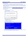
1
VF100 – Fixed Wireless Terminal Voice SMS Internet VoloFone™ VF100 User Manual Contents Safe and Efficient Use ....................................................................................................................... 4 Radio Frequency Energy ................................................................................................................... 4 Electronic Devices ............................................................................................................................. 4 About the VoloFone™ VF100 ............................................................................................................ 5 Voice Services ............................................................................................................................... 5 Internet Services ............................................................................................................................ 5 SMS Services ................................................................................................................................ 5 Getting Started .................................................................................................................................. 6 How to use this Manual ..................................................................................................................... 6 Conventions used in this Manual .................................................................................................... 6 Installing the USIM card..................................................................................................................... 7 Removing the USIM card ................................................................................................................... 7 VoloFone™ VF100 Connections ........................................................................................................ 8 Resetting the VoloFone™ VF100 ................................................................................................... 8 VoloFone™ VF100 Front Panel ....................................................................................................... 10 Signal Strength ............................................................................................................................ 10 Mobile Network Connection.......................................................................................................... 10 On/Off Hook ................................................................................................................................. 11 Message ...................................................................................................................................... 11 Local Area Network ...................................................................................................................... 11 Power Supply............................................................................................................................... 11 Setting up the VoloFone™ VF100.................................................................................................... 12 VoloFone™ VF100 Location ........................................................................................................ 12 Connecting the VoloFone™ VF100 to a Computer ........................................................................... 12 Preparation .................................................................................................................................. 12 Checking the Connection ............................................................................................................. 13 Voice Services................................................................................................................................. 15 VoloAdmin™ ................................................................................................................................... 15 APN (Access Point Name) ........................................................................................................... 15 The Test Button ........................................................................................................................... 15 SIM ................................................................................................................................................. 16 Power-on PIN Lock ...................................................................................................................... 16 Change PIN ................................................................................................................................. 17 PUK (Personal Unlocking Key) ..................................................................................................... 18 WAN ............................................................................................................................................... 19 Configuring the APN (Access Point Name) ................................................................................... 19 Configuring PPP Authentication ................................................................................................... 20 LAN ................................................................................................................................................. 21 Settings ....................................................................................................................................... 22 VPN ............................................................................................................................................. 22 Port Forward ................................................................................................................................ 23 Telephone ....................................................................................................................................... 24 Telephone Settings ...................................................................................................................... 24 Default Dial .................................................................................................................................. 25 Telephone Supplementary Services ............................................................................................. 26 Call Forwarding ............................................................................................................................ 26 Call Barring .................................................................................................................................. 27 Configuring Supplementary Services using the Phone Keypad ........................................................ 28 Introduction .................................................................................................................................. 28 Cancelling a Command ................................................................................................................ 30 Command Success/Failure Indication........................................................................................... 30 System Configuration ...................................................................................................................... 31 Password Change ........................................................................................................................ 31 Copyright © Vololink Pty Ltd 2006-08 V1.1 Jan 2008 Page 1 of 50 VoloFone™ VF100 User Manual Setting the Date and Time............................................................................................................ 32 Updating the VoloFone™ Firmware.............................................................................................. 32 Save/Restore Configuration ............................................................................................................. 34 Event Log ........................................................................................................................................ 36 Factory Defaults .............................................................................................................................. 37 Restarting the VoloFone™ VF100 ................................................................................................... 38 Creating a Login Shortcut (Optional) ................................................................................................ 39 SMS Services.................................................................................................................................. 39 Reply to an SMS message ........................................................................................................... 40 Forward an SMS message ........................................................................................................... 40 Delete an SMS message .............................................................................................................. 40 Creating a new SMS message ..................................................................................................... 41 Adding new entries to the Contacts page...................................................................................... 41 Editing an entry in the Contacts list............................................................................................... 42 Deleting an entry in the Contacts list ............................................................................................ 42 Saving a Draft Copy of a Message ............................................................................................... 42 Sent Messages ............................................................................................................................ 43 Troubleshooting............................................................................................................................... 44 Unable to Access VoloAdmin™ .................................................................................................... 46 No Internet Access ....................................................................................................................... 46 Telephone Service not available................................................................................................... 44 No LAN Connection ..................................................................................................................... 45 VoloFone™ VF100 fails to start normally ...................................................................................... 46 Glossary .......................................................................................................................................... 47 Technical Specification .................................................................................................................... 49 Copyright © Vololink Pty Ltd 2006-08 V1.1 Jan 2008 Page 2 of 50 VoloFone™ VF100 User Manual List of Tables Table of Access Point Names ................................................................................................................. 16 Table of Supplementary Phone Services................................................................................................. 29 COPYRIGHT NOTICE This document has been prepared and written by Vololink Pty Ltd, and is copyright. Other than for the purposes of and subject to the conditions prescribed under the Copyright Act, no part of it may in any form or by any means (electronic, mechanical, micro copying, photocopying, recording or otherwise) be reproduced, stored in a retrieval system or transmitted without prior written permission from Vololink Pty Ltd. Product or company names are trademarks or registered trademarks of their respective holders. Copyright © Vololink Pty Ltd 2006-08 V1.1 Jan 2008 Page 3 of 50 VoloFone™ VF100 User Manual Safe and Efficient Use Note: please read this information before using your VoloFone™VF100. Save this user manual as it contains important safety information and operating instructions. The VoloFone™ VF100 is intended for indoor use only. The VoloFone™ VF100 must not be connected to telephone cabling that leaves the building. Use only the supplied AC adaptor. Should it be necessary please return the VoloFone™ VF100 to your supplier for repair. The (optional) battery base of the VoloFone™ VF100 contains a backup battery. Ensure the main unit is securely located on the base. If mains power fails, the (optional) battery backup will continue to power the VoloFone™ VF100 for several hours. Once mains power returns, the (optional) backup battery will be recharged without any user intervention. If unit is going to be left without mains power for more than a few days, disconnect the (optional) backup battery by removing the base. This will prolong the battery life. The (optional) backup battery has an expected life of 5 years under normal use and conditions. Replace the (optional) backup battery only with the same type. There is a risk of explosion if the battery is replaced by an incorrect type. When installing a backup battery in the base of the VoloFone™ VF100, ensure the battery cable is installed with correct polarity: the positive (red) lead should go to the positive (red) battery terminal. Radio Frequency Energy Your VoloFone™ VF100 is both a radio transmitter and receiver. When the VoloFone™ VF100 is turned on, it receives and transmits RF (Radio Frequency) energy. The system that handles your call when you are using your VoloFone™ VF100 controls the power level at which your VoloFone™ VF100 transmits. All VoloFone™ VF100 terminals are designed to operate within the limits for exposure to RF energy set by national authorities and international health agencies. These limits are verified by SAR (Specific Absorption Rate) measurements; which are usually performed on products that are intended for use at the ear. As the VoloFone™ VF100 is not intended be used close to the human body SAR measurements are not applicable to the VoloFone™ VF100. Electronic Devices Most modern electronic equipment, for example equipment in hospitals and cars, is shielded from the effects of RF energy. However, certain electronic equipment is not, so the RF energy from the VoloFone™ VF100 may affect some electronic equipment, therefore: Do not use your VoloFone™ VF100 near medical equipment without requesting permission. Do not use your VoloFone™ VF100 in airplanes. Pacemaker patients should be aware that the use of a VoloFone™ VF100 close to a pacemaker may cause the pacemaker to malfunction. Some hearing aids might be disturbed if placed very close to the VoloFone™ VF100. Electrical devices connected to the same AC power outlet that is used by the VoloFone™ VF100 may generate excessive interference to the VoloFone™ VF100. Copyright © Vololink Pty Ltd 2006-08 V1.1 Jan 2008 Page 4 of 50 VoloFone™ VF100 User Manual About the VoloFone™ VF100 Vololink has developed one of the leading fixed wireless terminal products available today for the UMTS market. The VoloFone™ VF100 is a 3G WCDMA/UMTS tri-band product which can be used anywhere in the world. The product operates across the 850, 1900 and 2100 MHz wireless bands. The VoloFone™ VF100 is also capable of operating across the GSM/GPRS/EDGE bands, namely the 850, 900, 1800 and 1900 MHz bands. The product automatically defaults to these wireless bands where 3G network services are not available. The product is designed to be free standing. A VoloFone™ VF100 is the equivalent of a combined internet connection and a phone line. Telephone handsets and computer equipment can be connected in the normal way using a standard RJ11 telephone jack and RJ45 Ethernet connector. Just add an activated USIM card and power it up and in an area where there is 3G signal (or GSM/GPRS/EDGE signal) and the communications services will be instantly available. Once the VoloFone™ VF100 has been connected and powered up, the following services are available: Voice Services The VoloFone™ VF100 provides the equivalent of a PSTN or fixed line connection via the 3G mobile network. Just plug in a standard analogue handset or an answering system with extension handsets. The VoloFone™ VF100 is compatible with most RJ11 based handset solutions available on the market today that support tone dialling. The VoloFone™ VF100 does not support old handsets that are capable of pulse dialling only. Internet Services The VoloFone™ VF100 provides a true broadband solution with HSDPA services enabled on the 3G network. Connect your computer and you will be able to surf the Internet at speeds up to 7.2 MBits per second. SMS Services The VoloFone™ VF100 is a 3G mobile device so you can receive and send SMS messages. On your computer you can create, view and reply to SMS messages in the same way you would with any mobile phone. Copyright © Vololink Pty Ltd 2006-08 V1.1 Jan 2008 Page 5 of 50 VoloFone™ VF100 User Manual Getting Started The first step is to check that the VoloFone™ VF100 package that you have purchased is complete. The following is the packing list: 1 VoloFone™ VF100 1 Base 1 Backup battery (Optional) 1 Power Supply and power cable 1 Ethernet Cable 1 RJ11 Telephone Cable 1 Antenna 1 CD (Contains the User Manual) If any component is missing, please contact the retailer where you purchased the VoloFone™. How to use this Manual The manual is arranged in easy to follow sections. Use the Contents page to locate a particular topic. Each section refers to its functionality as follows: Voice How to use the VoloFone™ VF100 as a Phone connection. Internet How to use the VoloFone™ VF100 as your Internet connection. SMS How to use the VoloFone™ VF100 to send and receive SMS messages. As with computers, there is a lot of jargon and acronyms associated with wireless communications. To make understanding this manual easier, a Glossary of Terms is included. For the technically minded a full Specification Sheet is included at the end of this manual. There is a Troubleshooting section to assist with any difficulties that you may have with the VoloFone™ VF100. Conventions used in this Manual A list has bullets in the left margin - the same bullets as used in this list. An important note or warning has the A suggestion or hint has the Informational text has the Emphasized text is displayed bold. Critical text is displayed in bold bright red. Hyperlinks are displayed in underlined blue. Copyright © Vololink Pty Ltd 2006-08 icon in the left margin. icon in the left margin. icon in the left margin. V1.1 Jan 2008 Page 6 of 50 VoloFone™ VF100 User Manual Installing the USIM card Before attempting to install the USIM card, disconnect the power pack. The USIM card is installed in the underside of the VoloFone™ VF100. To install the USIM card proceed as follows: 1 Turn the VoloFone™ over to reveal the USIM slot shown below. Front ► 2 Insert the USIM card with the cut corner facing the front of the VoloFone™ VF100. 3 Gently press the USIM card into the slot. You will feel a click as the card seats. USIM shown fitted ► 4 Place the VoloFone™ VF100 back onto the base and push down to lock together. Removing the USIM card Before attempting to remove the USIM card, disconnect the power pack. To remove the USIM card simply press gently on the card. You will feel a click as the card is released. The card is ejected from the USIM slot. Copyright © Vololink Pty Ltd 2006-08 V1.1 Jan 2008 Page 7 of 50 VoloFone™ VF100 User Manual VoloFone™ VF100 Connections The following diagram shows the rear panel of the VoloFone™ VF100 and describes the purpose of each connection. Antenna (RF) – attach the supplied antenna to this connector. Serial port – this is used for diagnostic/maintenance purposes/reserved for future use. USB (Universal Serial Bus) port – this is used for diagnostic/maintenance purposes/reserved for future use. Ethernet port (LAN) – plug a network cable in here. The Link light (green) denotes a network connection. The Activity light (yellow) denotes network traffic. Phone port (RJ11) – connect a phone here. Power Supply – connect the power supply cable here. Reset Button – Use a paper clip to reset the VoloFone™ VF100. See below for further information on resetting the VoloFone™ VF100. Resetting the VoloFone™ VF100 The unit can be reset at any time after the first LEDs sequence appears after a power cycle. This is done by pressing and holding down the reset button (use a paperclip to do this). The VoloFone™ acknowledges the reset button press using its front panel LEDs: 1. LEDs turn red - first acknowledgment of reset button press. 2. LEDs turn green - 5 seconds after first acknowledgment. 3. LEDs turn red again - 10 seconds after first acknowledgement. The reset button of the VoloFone™ VF100 has three functions: 1. Reboot the VoloFone™ VF100 Press and hold the reset button down for a period between the first and second indications; that is, less than 5 seconds (between the first red LEDs and the green LEDs indication). This is equivalent to cycling the power of the VoloFone™ VF100 by unplugging it from the battery base (if applicable) and unplugging the power supply. Copyright © Vololink Pty Ltd 2006-08 V1.1 Jan 2008 Page 8 of 50 VoloFone™ VF100 User Manual 2. Reset the VoloFone™ VF100 configuration to factory defaults Press and hold the reset button for a period between indication step 2 and 3; that is, until after the LEDs turn green (more than 5 seconds) and release the button before the LEDs turn red again (less than 10 seconds). 3. Clear the VoloFone™ VF100 flash memory Press and hold the reset button for a period of greater than 10 seconds, until after the LEDs turn red again. This will wipe the user area of flash memory which includes SMS messages and the Event Log. This final action should be used as a last resort when troubleshooting a problem with your VoloFone™ VF100. Copyright © Vololink Pty Ltd 2006-08 V1.1 Jan 2008 Page 9 of 50 VoloFone™ VF100 User Manual VoloFone™ VF100 Front Panel The following diagram shows the front panel of the VoloFone™ VF100 and describes what each of the indicator lights represent. Signal Strength Mobile Network Connection See below for further information on each of the indicator lights. On/Off Hook Message Local Area Network (LAN) Power Supply Blue when power is supplied to the VoloFone™ VF100. Signal Strength Four indicators display the received signal strength. This is similar to a mobile phone signal strength indicator. The following table describes the behaviour of the Signal Strength meter. Status Signal Strength meter display Signal present Green – 1 to 4 bars depending on signal strength Weak signal Orange – 1 bar No signal present No display Mobile Network Connection The following table describes the behaviour of the Mobile Network Connection light. Status Broadband Connection display Searching for a mobile network Orange – flashing at 1 second intervals Connected to a GPRS/EDGE data network Green – flashing at 1 second intervals Connected to a UMTS/HSDPA data network Green – flashing at 200 millisecond intervals Connected to a mobile network – voice and SMS available, but no connection Green – solid SIM is not available (missing or locked) Red – solid Copyright © Vololink Pty Ltd 2006-08 V1.1 Jan 2008 Page 10 of 50 VoloFone™ VF100 User Manual On/Off Hook The following table describes the behaviour of the On/Off Hook light. Status On/Off Hook light display Phone is On Hook and idle Green – solid Phone is Off Hook Green – flashing at a consistent rate Phone is receiving a call or dialling out Green – flashes twice then pauses. Pattern repeats until phone is hung up Message The following table describes the behaviour of the Message light. Status Message light display No new messages in the SMS inbox No display New message in the SMS inbox Green – flashing Local Area Network The following table describes the behaviour of the LAN light. Status LAN light display No network cable connected to the VoloFone™ No display Network cable is connected to the VoloFone™ and a LAN is present. (Same functionality as the green Link light on the Ethernet [LAN] port) Green – solid Network traffic is detected. (Same functionality as the yellow Activity light on the Ethernet [LAN] port) Green – flashing Power Supply The following table describes the behaviour of the Power Supply light. Status Power light display The VoloFone™ is running on the backup battery Red - solid The VoloFone™ is running on the backup battery. The reserve capacity has dropped to a critical level Red – flashing The VoloFone™ is connected to mains power and the backup battery is charging Orange – solid The VoloFone™ is connected to mains power and the backup battery is fully charged Green – solid The VoloFone™ is connected to mains power with no backup battery Green – solid The Blue Power light is always on when power is supplied to the VoloFone™ VF100. During start up, the VoloFone™ VF100 lights will go through the following sequence before resuming normal operations: All Lights Orange - Chaser Sequence* of Red and Green - All Lights Off * The Chaser Sequence involves all lights from the Mobile Network Connection down to the Power Supply. Copyright © Vololink Pty Ltd 2006-08 V1.1 Jan 2008 Page 11 of 50 VoloFone™ VF100 User Manual Setting up the VoloFone™ VF100 VoloFone™ VF100 Location The signal strength available at the VoloFone™ VF100 location affects the performance of the unit. The stronger the signal, the better the VoloFone™ VF100 performance. Test several locations by moving the VoloFone™ VF100 while looking at the Signal Strength Lights. (Wait 10 to 20 seconds after each change of location for the Signal Strength to be measured and displayed). Select a location where the maximum number of Signal Strength Lights are active. Moving the VoloFone™ VF100 as little as 5 cm can affect the Signal Strength. Recommendations: Select an indoor location, preferably close to a window and the roof. Generally, you will experience better Signal Strength in these locations. Do not install the VoloFone™ VF100 in a bathroom, a wet or damp environment or an outdoor location. Do not install the VoloFone™ VF100 in locations or rooms that contain large amounts of metal, steel or wiring. Locations that contain large amounts of metal inhibit the transmission of Radio Frequency (RF). Do not expose the VoloFone™ VF100 to extreme temperatures (near radiators, cooling vents, etc). If you experience poor Signal Strength, an (optional) higher gain antenna may result in improvement. Connecting the VoloFone™ VF100 to a Computer The VoloFone™ VF100 is connected to a computer using the Ethernet (LAN) port on the back of the unit and the Ethernet port on the computer. Use a standard Universal Twisted Pair (UTP) network cable with RJ45 connectors for this purpose. If the computer that you are connecting to the VoloFone™ VF100 is already configured to obtain an IP Address and DNS server address automatically (which is usually the case), you can skip this section and move to Checking the Connection. If this is not the case, continue with the Preparation section following. Preparation To prepare the computer for connection to the VoloFone™ VF100 do the following: In Windows XP: Load Windows Control Panel and double-click Network Connections. Under the heading LAN or High-Speed Internet right-click Local Area Connection and select Properties. Select Internet Protocol (TCP/IP) and click the Properties button. A dialog box similar to the one below appears. In Windows Vista: Load Windows Control Panel and double-click Network and Sharing Center. Next to Local Area Connection, click View status. The Local Area Connection Status window is displayed. Click the Properties button. The Local Area Connection Properties window is displayed. Select Internet Protocol Version 4 (TCP/IPv4) and click the Properties button. Copyright © Vololink Pty Ltd 2006-08 V1.1 Jan 2008 Page 12 of 50 VoloFone™ VF100 User Manual A dialog box similar to the following appears (Windows Vista shown here) Ensure that Obtain an IP address and Obtain DNS Server address are both set to automatic. The VoloFone™ VF100 is a DHCP server and will provide both of these addresses. Checking the Connection When the VoloFone™ VF100 has been connected and the above steps completed, check that a connection exists between the VoloFone™ VF100 and the computer. This is done by viewing the (Green) Link light on the VoloFone™ VF100 and computer LAN connectors. They should both be lit and steady. The next step is to connect to the VoloAdmin™ interface as follows: Open your browser and enter the address http://192.168.0.1 in the Address line shown below, then press Enter. Copyright © Vololink Pty Ltd 2006-08 V1.1 Jan 2008 Page 13 of 50 VoloFone™ VF100 User Manual The VoloFone™ Log In dialog appears. Type the Username admin Type the default Password password (you can change this later) Click the OK button - the VoloFone™ Index page appears: Click VoloAdmin - the VoloAdmin™ Status page is displayed. If the WAN State is Connected, you are ready to use your VoloFone™ VF100 to surf the Internet. If this is not the case, continue by configuring the APN (Access Point Name). Copyright © Vololink Pty Ltd 2006-08 V1.1 Jan 2008 Page 14 of 50 VoloFone™ VF100 User Manual Voice Services To use the VoloFone™ VF100 as a wireless telephone connection: Plug the phone lead into the RJ11 (Phone) port on the back of the VoloFone™ VF100. Lift the handset (you should hear a dial tone) and dial the number you wish to call. The Phone Light on the front of the VoloFone™ VF100 will flash when the handset is off-hook. If Power-on PIN Lock has been enabled, the dial tone will be different (an intermittent tone instead of the normal dial tone). Unlock the SIM using the telephone keypad by entering the PIN followed by # then replace the handset. VoloAdmin™ This section covers the administration of the VoloFone™ VF100. There are many configurable features; however, it is only necessary to configure one setting to make your VoloFone™ VF100 work. The setting that you need to configure is: APN (Access Point Name) If your VoloFone™ VF100 was purchased as a packaged unit including a configured USIM, you do not need to configure the APN. It is recommended that even if you have a pre-configured unit, you complete the next step and record the APN. This is to save time obtaining it from your service provider in the event it is lost due to a configuration error or a reset some time in the future. What is the Access Point Name? – The APN is the name of your ISP’s wireless access point. To configure the APN for your ISP, start by loading VoloAdmin™ as described above. From the Navigation panel on the left select Quick Setup - the Quick Setup page appears: Enter the name of your ISP’s Access Point in the editbox provided. Click the Apply button. The Test Button On many of the configuration pages a Test button is present. Use the Test button to test the functionality that you have just configured. When you are satisfied with the new configuration, click the Apply button. Clicking the Apply button saves any changed settings permanently in non-volatile memory. Copyright © Vololink Pty Ltd 2006-08 V1.1 Jan 2008 Page 15 of 50 VoloFone™ VF100 User Manual The following is a sample list of local (Australian) Access Points. For further information contact your Internet Service Provider. Table of Access Point Names ISP Network APN Optus Optus internet Optus Data Only Optus connect Telstra Telstra (2G) telstra.wap Telstra Telstra (3G) telstra.internet Telstra Telstra (3G data bundles) telstra.datapack Telstra Telstra (Pay by time) pcpack Three Three 3netaccess Vodafone Vodafone vfinternet.au The rest of this section covers items that you may wish to view or change. SIM To access the SIM options, click SIM in the navigation panel – the SIM page appears. Use this page is to manage the function of the PIN. From this page you can: Enable/Disable Power-on PIN Lock Change the PIN If the Power-on PIN Lock is disabled, Change PIN is not available. Power-on PIN Lock To configure Power-on PIN Lock proceed as follows: Click the drop-down list next to Ask for SIM PIN at Power Up and select Enabled then click the Apply button You are then prompted to enter the Current PIN as confirmation: Copyright © Vololink Pty Ltd 2006-08 V1.1 Jan 2008 Page 16 of 50 VoloFone™ VF100 User Manual Enter the current PIN in the editbox provide and click the Apply button The page changes to reflect the Enabled state and provide the Change PIN facility as follows: When Power-on PIN Lock is enabled: 1. The dial tone is different when using the telephone (an intermittent tone instead of the normal dial tone). Unlock the SIM using the telephone keypad by entering the PIN followed by # then replace the handset. 2. Connection to Broadband services is disabled. To enable connection to Broad band services, unlock the SIM using the telephone keypad (described above) or, use VoloAdmin™. You can enter the SIM PIN in the Status, SIM or Quick Setup pages of VoloAdmin™ as follows: Enter the SIM PIN then click Apply. The Enter PIN to Unlock field only appears if Power-on PIN Lock is enabled. Copyright © Vololink Pty Ltd 2006-08 V1.1 Jan 2008 Page 17 of 50 VoloFone™ VF100 User Manual Change PIN To change the PIN do the following: Enter the new PIN in the editbox provided. Re-enter the new pin in the Repeat new PIN editbox. Click the Apply button to make the change. You are then prompted to enter the old PIN as confirmation. Enter the current (old) PIN in the editbox provided and click the Apply button. The PIN is now changed. PUK (Personal Unlocking Key) If you enter your PIN incorrectly three times, the SIM is locked and the following page is displayed. You will need to contact your service provider to obtain the PUK for your SIM. To unlock the SIM proceed as follows: Enter the PUK in the editbox provided. Enter a new PIN in the editbox provided. Click the Apply button. After a short delay The Mobile Network Connection light on the front of the VoloFone™ VF100 changes from red to green. The Network State changes from Offline to Logged on UMTS/HSDPA. The WAN State changes from Not connected, network not online to Connected. Copyright © Vololink Pty Ltd 2006-08 V1.1 Jan 2008 Page 18 of 50 VoloFone™ VF100 User Manual WAN To view the WAN (Wide Area Network) status and configure PPP (Point to Point Protocol) Authentication click WAN on the Navigation panel - the WAN page appears: The WAN page displays the following: Wireless Broadband Status Displays current connection status, your server assigned IP address and Subnet Mask, the IP addresses of your ISP’s DNS (Domain Name Server) and the MTU (Maximum Transmission Unit) value set on your computer. Traffic Statistics Shows the number of packets and bytes transmitted (TX) and received (RX). Configuration Allows you to define your ISP’s APN. You can also configure PPP Authentication. See below for information on configuring the APN and PPP Authentication. Configuring the APN (Access Point Name) Enter the name of your ISP’s Access Point in the editbox provided. Click the Apply button. Copyright © Vololink Pty Ltd 2006-08 V1.1 Jan 2008 Page 19 of 50 VoloFone™ VF100 User Manual Configuring PPP Authentication In most cases PPP authentication is not required by an ISP. PPP authentication provides that a host, before establishing a PPP connection, may require that the other host uniquely identify itself using prearranged, secure data known to both hosts. This is in the form of a PPP Username and PPP Password pair. To configure PPP Authentication proceed as follows: Click the drop-down list next to PPP Authentication (see below) and select Enabled then click the Apply button. The page will update to include PPP Username and Password entries. Enter the PPP Username in the editbox provided. Enter the PPP Password in the editbox provided. Click the Apply button. Copyright © Vololink Pty Ltd 2006-08 V1.1 Jan 2008 Page 20 of 50 VoloFone™ VF100 User Manual LAN To view the LAN (Local Area Network) status and traffic statistics click LAN in the Navigation panel - the LAN page appears: The LAN Status page displays the following: MAC Address The MAC (Media Access Control) address of the VoloFone™ VF100. IP Address and Netmask The IP (Internet Protocol) Address and Netmask of the VoloFone™ VF100. MTU MTU (Maximum Transmission Unit) value set on the VoloFone™ VF100. DHCP Server The status of the DHCP (Dynamic Host Configuration Protocol) Server in the VoloFone™ VF100. Traffic Statistics displays the following: RX Packets and Bytes The number of data Packets and Bytes received. TX Packets and Bytes The number of data Packets and Bytes transmitted. Collisions The number of collisions on the network. Copyright © Vololink Pty Ltd 2006-08 V1.1 Jan 2008 Page 21 of 50 VoloFone™ VF100 User Manual Settings To view or edit the LAN Settings select LAN followed by Settings in the Navigation panel - the LAN Settings page appears: Most users will not need to change anything on this page. However, if necessary, you can define the IP Address and Netmask of the VoloFone™ VF100 as well as Enable or Disable the DHCP Server together with the IP Range (assigned by the DHCP Server) and the Lease Time of the IP Address. The VoloFone™ VF100 incorporates a DHCP server that assigns dynamic IP addresses to local clients (computers connected to the VoloFone™ VF100). The IP addresses are allocated from the predefined range of addresses defined on this page. The default address range is suitable for most local networks. The DHCP server allocates the IP address for the term of the Lease Time defined on this page. The lease is the amount of time that an IP address is valid for a specific device. If the lease expires and the device is still connected, the lease is automatically renewed. VPN The VoloFone™ VF100 can be configured as a VPN (Virtual Private Network) Host. To do this, proceed as follows: Select LAN followed by VPN in the Navigation panel - the VPN Page appears: Select Enabled from the drop-down list. Click the Apply button - the VPN page reappears with the VPN configuration items ready for you to complete. Copyright © Vololink Pty Ltd 2006-08 V1.1 Jan 2008 Page 22 of 50 VoloFone™ VF100 User Manual You will need to obtain the following information from the administrator of the remote server: Remote Host Address Remote Network Address Remote Network Mask Remote Network Gateway Authentication Key – A Pre-Shared Key (PSK) Port Forward Port forward is used to allow an external user to reach a port on a private IP address (inside a LAN) from the outside via a NAT-enabled router (VoloFone™ VF100). When a computer on the Internet sends data to the public IP address of the VoloFone™ VF100, it needs to know how to manage the data. Port Forward tells the VoloFone™ VF100 which computer on the local area network to send the data to. To configure Port Forward select LAN followed by Port Forward in the Navigation panel - the Port Forward page is displayed: Enter the Server IP address and Server Port, select the Protocol from the drop-down list, and enter the NAT Port then click the Add button. Copyright © Vololink Pty Ltd 2006-08 V1.1 Jan 2008 Page 23 of 50 VoloFone™ VF100 User Manual Example In this example, port forward is used to allow incoming access to an internal web server. Configuration Item Explanation Server IP: 192.168.0.100 The IP address of the server on the internal network where the port will be forwarded. Server Port: 8080 The port number on the internal server. Protocol: TCP The protocol to be forwarded. NAT Port: 80 The port number on the VoloFone™ VF100 to be forwarded. Telephone To configure how the attached telephone works, select Telephone from the Navigation panel - the Telephone page is displayed: Telephone Settings The following settings can be configured: Volume This is the handset earpiece volume (1- quietest, 4 – loudest). DTMF Dial Timeout Define the time from dialling to call setup. This is the time lag between when you finish keying the number to call, and when the phone starts to dial. The timeout range is between 2 and 10 seconds. The default setting is 3 seconds. Country/Region Select from the drop-down list. Copyright © Vololink Pty Ltd 2006-08 V1.1 Jan 2008 Page 24 of 50 VoloFone™ VF100 User Manual Default Dial Default Dial is a number that you can configure for the VoloFone™ VF100 to dial simply by lifting the handset. This feature can be used as an emergency call facility. To implement this feature, Enable Default Dial using the drop-down list then click Apply. The page reappears with Default Dial enabled. Enter the Default Dial Timeout and the Default Dial number. The valid range for the timeout is between 2 and 10 seconds. The default setting is 5 seconds. Copyright © Vololink Pty Ltd 2006-08 V1.1 Jan 2008 Page 25 of 50 VoloFone™ VF100 User Manual Telephone Supplementary Services Support of Supplementary Services is dependent on the cellular module (USIM) installed in the VoloFone™ VF100 and also on the network. For this reason, all of the documented services may not be available. You can also configure: Inbound Caller ID To display the Caller ID of an incoming call on a Caller ID capable handset. Outbound Caller ID Own Number sending. Call Waiting Call Waiting notification. To enable/disable these settings, use the drop-down list then click the Apply button. Call Forwarding To configure Call Forwarding, select Telephone followed by Call Forwarding in the Navigation panel the Call Forwarding page is displayed: Copyright © Vololink Pty Ltd 2006-08 V1.1 Jan 2008 Page 26 of 50 VoloFone™ VF100 User Manual You can configure the following: Forward All Voice Calls Unconditional Call Forward. Forward Voice Calls when Phone is Busy Busy Call Forward. Forward Voice Calls when Calls are Not Answered No Answer Call Forward after defined number of seconds. Forward Voice Calls when Phone is Not Reachable Phone Not Reachable Call Forward. To enable any of these settings first enter a phone number to forward to, use the drop-down list to select Enabled, and then click the Apply button. To disable a setting, use the drop-down list to select Disabled, and then click the Apply button. Call Barring To configure Call Barring, select Telephone followed by Call Barring in the Navigation panel - the Call Barring page is displayed: Copyright © Vololink Pty Ltd 2006-08 V1.1 Jan 2008 Page 27 of 50 VoloFone™ VF100 User Manual You can configure Call Barring for: Call Type All Calls Incoming Calls Outgoing Calls Setting Explanation Disable Call Barring for All Calls No Call Barring is active. All Incoming Call Barring Disabled No Call Barring is active for All Incoming Calls to the VoloFone™. All Incoming Calls Barred All Incoming Calls to the VoloFone™ are Barred. All Incoming International Calls when Roaming Barred All Incoming International Calls are barred when the VoloFone™ is Roaming. All Outgoing Call Barring Disabled No Call Barring is active for All Outgoing Calls from the VoloFone™. All Outgoing Calls Barred All Outgoing Calls from the VoloFone™ are Barred. All Outgoing International Calls Barred All Outgoing International Calls from the VoloFone™ are Barred. All Outgoing International Calls except to Home Country Barred All Outgoing International Calls from the VoloFone™ are Barred except those to your Home Country. To configure these settings, use the drop-down list to select the action, enter the Password and click the Apply button. You will need to obtain the password for Call Barring from your service provider. Configuring Supplementary Services using the Phone Keypad Introduction Support of Supplementary Services is dependent on the cellular module (USIM) installed in the VoloFone™ VF100 and also on the network. For this reason, all of the documented services may not be available. The VoloFone™ VF100 supports the following list of Supplementary Services. Inbound Caller ID Outbound Caller ID Call Waiting Call Forwarding Call Barring Multi-party Calls Call Transfer Call Holding Call Waiting Throughout this section the instructions will refer to the Flash key on the telephone. Not all telephones have a Flash key, however, briefly pressing the On/Off hook button (also known as the Talk button) on the telephone has the same functionality as the Flash key. When you see this icon in the instructions, lift the telephone handset Off Hook. When you see this icon in the instructions, replace the telephone handset On Hook. Keypad commands will work with a DTMF capable (tone dialling) phone only. Copyright © Vololink Pty Ltd 2006-08 V1.1 Jan 2008 Page 28 of 50 VoloFone™ VF100 User Manual Table of Supplementary Phone Services Feature Keypad sequence General Settings Inbound Caller ID enable *30Flash #30Flash Inbound Caller ID disable Outbound Caller ID enable *31Flash #31Flash Outbound Caller ID disable Call Waiting enable *43Flash #43Flash Call Waiting disable Volume Setting (Where Volume Level = 1 – 4) #69* [Level] Flash Caller ID Notes Only applicable for handsets that support Caller ID Display. This feature must be disabled if the handset does not support it. Call Forwarding In the following section [number] is the number to forward to. Forward all Voice Calls enable *21*[number]*Flash #21*[number]*Flash Forward all Voice Calls disable Forward Call when Phone is Busy enable *67*[number]*Flash #67*[number]*Flash Forward Call when Phone is Busy disable Forward Call when No Reply enable *61*[number]*[delay]Flash Forward Call when No Reply disable #61*[number]*[delay]Flash (where delay is 5 to 30 seconds) Forward Call when Not Reachable enable *62*[number]*Flash #62*[number]*Flash Forward Call when Not Reachable disable Call Forwarding Notes: 1. If all voice calls are barred; this will take precedence over all other settings. 2. If Phone is Busy, No Reply or Not Reachable is activated when All Voice Call Barring is active; it will first deactivate All Voice Call Barring. Call Barring You will need to obtain the password for Call Barring from your service provider. All Call Barring disable #330*<password>Flash Bar all Incoming Calls enable *35*<password>Flash #35*<password>Flash Bar all Incoming Calls disable Bar All Incoming International Calls when Roaming enable Bar All Incoming International Calls when Roaming disable *351*<password>Flash #351*<password>Flash All Incoming Call Barring disable #353*<password>Flash Bar All Outgoing Calls enable Bar All Outgoing Calls disable *33*<password>Flash #33*<password>Flash This section continued on next page... Copyright © Vololink Pty Ltd 2006-08 V1.1 Jan 2008 Page 29 of 50 VoloFone™ VF100 User Manual Call Barring continued Bar All Outgoing International Calls enable Bar All Outgoing International Calls disable *331*<password>Flash #331*<password>Flash Bar All Outgoing International Calls except to Home Country enable Bar All Outgoing International Calls except to Home Country disable *332*<password>Flash #332*<password>Flash All Outgoing Call Barring disable #333*<password>Flash The next section refers to In Call features. These commands are executed while a call is in progress. Feature Keypad sequence Answer a Call in Waiting Flash2# Alternates between the calls Multiparty Call – A call is in progress and there is another incoming call Flash2# to put current call on hold and pick up the incoming call; then, Flash3# to connect all calls Multiparty Call – A call is in progress and you make another call Call Transfer Flash2# to put current call on hold, make another call by Flash[number]*, when call is answered, Flash3# to connect all calls Flash4# to disconnect self and connect the other two calls. Cancelling a Command For all commands except the In-Call Feature commands, hanging up the telephone handset or pressing the Cancel button in VoloAdmin™ will cancel it. Command Success/Failure Indication For a command entered using the keypad, you will hear a higher pitch tone to indicate success. A lower pitch tone indicates failure. Copyright © Vololink Pty Ltd 2006-08 V1.1 Jan 2008 Page 30 of 50 VoloFone™ VF100 User Manual System Configuration Password Change The default password for your VoloFone™ VF100 is “password”. This should be changed to protect access to your VoloFone™ VF100. To change the default password, follow these steps: From the Navigation panel, select System - the System page appears. Under the System Information heading the following items appear: Model Name This is the Model Name of your VoloFone™ VF100. System Uptime The lapsed time since your VoloFone™ VF100 was powered on. Firmware Version The Version Number of the Firmware installed on your VoloFone™ VF100. Serial Number The Serial Number of your VoloFone™ VF100. IMEI The International Mobile Equipment Identity number. A number unique to every GSM and UMTS mobile device, in this case, your VoloFone™ VF100. The IMEI number is used identify the device only, it is not related to the SIM or the subscriber. Under the System Settings heading the following items appear: VoloAdmin™ Password This is where you can change your VoloAdmin™ password. Language Select the Language from the drop-down list. To change your VoloAdmin™ Password: Enter your new password in the editbox, then click the Apply button. You are prompted to Log in using the new password. Enter the new password and click the OK button. Copyright © Vololink Pty Ltd 2006-08 V1.1 Jan 2008 Page 31 of 50 VoloFone™ VF100 User Manual Setting the Date and Time To set the Date and Time on your VoloFone™ VF100 follow these steps: From the Navigation panel select System followed by Date/Time - the Date and Time page appears: By default, the NTP (Network Time Protocol) Server is enabled, meaning the VoloFone™ VF100 will synchronise the date and time with a time server and the Date and Time fields are not enabled for editing. If you wish to control the time and date setting locally, disable the NTP Server as follows: From the drop-down list select Disabled then click the Apply button – the page will reload with the Date and Time fields enabled for editing. Enter the current Date and Time. Select your Local Timezone Offset from the drop-own list. Click the Apply button to save the settings. Updating the VoloFone™ Firmware From time to time it may be necessary to update the VoloFone™ VF100 firmware. To obtain updated firmware please contact your VoloFone™ supplier then proceed as follows: Click the Browse button to locate the Firmware Update file - a browse box opens. Copyright © Vololink Pty Ltd 2006-08 V1.1 Jan 2008 Page 32 of 50 VoloFone™ VF100 User Manual Select the Firmware Update file. Click the Open button to select the update. Click the Update Firmware button to start the process. The Firmware update will take approximately 3 minutes to complete. Make sure that you click Update Firmware only once. Do not attempt to cancel or interrupt the firmware update. Do not navigate away from this page until the update is complete. After approximately 3 minutes the Firmware Update Complete page appears: Click Restart to activate the updated firmware - the Restart VF100 page appears: From the Confirm Restart drop-down list select Restart now, and then click Apply. The Restarting page appears prompting you to “wait for 60 seconds then click refresh”. If JavaScript is enabled in your Web browser, it is not necessary to click refresh to reload the page – the refresh will happen automatically. Copyright © Vololink Pty Ltd 2006-08 V1.1 Jan 2008 Page 33 of 50 VoloFone™ VF100 User Manual After clicking refresh, the VoloAdmin™ Index page appears. Save/Restore Configuration It is good practice to Save your VoloAdmin™ configuration to a file so that it may be Restored at a later date if it is necessary to recover from a configuration error. To do so, proceed as follows: Select System followed by Save/Restore in the Navigation panel - the Save/Restore page appears: Click the Save Configuration button. A confirmation dialog appears. Click the Save button. Copyright © Vololink Pty Ltd 2006-08 V1.1 Jan 2008 Page 34 of 50 VoloFone™ VF100 User Manual The Save As dialog appears. Select a location to save the backup configuration file. Click the Save button to complete the task. To Restore a saved configuration: Under the heading Restore Configuration click the Browse button - a dialog opens for you to locate and select the previously saved backup configuration file. Click the Restore Configuration button. Do not attempt to cancel or interrupt this operation. After the upload has completed it is necessary to restart the VoloFone™ VF100 for the restored configuration to take effect. Copyright © Vololink Pty Ltd 2006-08 V1.1 Jan 2008 Page 35 of 50 VoloFone™ VF100 User Manual Event Log To view the Event Log select System followed by Event Log in the Navigation panel - the Event Log page appears: Events are displayed in groups of 20 items. Use the Back/Forward keys (see below) at the bottom of the page to move through the Event Log. Move to the first page of the Event Log. Move to the previous page of the Event Log. Move to the next page of the Event Log. Move to the last page of the Event Log. If you lodge a support request you may be asked to view the Event Log to assist in diagnosis. Copyright © Vololink Pty Ltd 2006-08 V1.1 Jan 2008 Page 36 of 50 VoloFone™ VF100 User Manual Factory Defaults Before setting your VoloFone™ VF100 back to factory defaults make a note of any items that you have configured as they will be lost during the reset. These items include the APN, PPP Authentication credentials, LAN configuration etc. The VoloFone™ VF100 User ID and Password will also revert to the default values of “admin” and “password”. To restore the VoloFone™ VF100 to the factory settings select Factory Defaults from the Navigation panel - the Factory Defaults page appears: Select Yes from the drop-down list. Click the Apply button. The VoloFone™ VF100 will restart. Click Refresh when prompted. You will need to re-enter the APN before the VoloFone™ VF100 will connect to the Internet. Copyright © Vololink Pty Ltd 2006-08 V1.1 Jan 2008 Page 37 of 50 VoloFone™ VF100 User Manual Restarting the VoloFone™ VF100 To restart the VoloFone™ VF100 select Restart VF100 from the Navigation panel - the Restart VF100 page is displayed: From the Drop-down list select Restart Now. Click the Apply button - the Restarting VF100 page appears prompting you to “Please wait 60 seconds then click refresh”. Click refresh to reload the page. If JavaScript is enabled in your Web browser, it is not necessary to click refresh to reload the page – the refresh will happen automatically. Copyright © Vololink Pty Ltd 2006-08 V1.1 Jan 2008 Page 38 of 50 VoloFone™ VF100 User Manual Creating a Login Shortcut (Optional) To make logging in to your VoloFone™ VF100 easier, create a bookmark in your browser to go to the VoloFone™ VF100 Login dialog as follows: In Internet Explorer®, enter the address http://192.168.0.1 and press Enter to access the VoloFone™ VF100 Login dialog. Continue by selecting the Favourites menu and clicking Add to Favourites. In Netscape Navigator® or Mozilla Firefox®, enter the address http://192.168.0.1 and press Enter to access the VoloFone™ VF100 Login dialog. Continue by selecting the Bookmarks menu and clicking Bookmark this page or use the keyboard shortcut Ctrl+D. SMS Services To use the VoloFone™ VF100 to send and receive SMS messages it is necessary to access the VoloSMS™ page using a browser. To do this, proceed as follows: ● Open your browser and enter the address http://192.168.0.1 in the Address line shown below, then press Enter. The VoloFone™ Log In dialog appears. ● Enter the Username admin. ● Followed by the Password password. ● Click the OK button - the VoloFone™ - Index page appears. ● Click VoloSMS™ - the VoloSMS™ Inbox page appears. Copyright © Vololink Pty Ltd 2006-08 V1.1 Jan 2008 Page 39 of 50 VoloFone™ VF100 User Manual On this page you can read SMS messages received by your VoloFone™ VF100. When a new SMS message is received, the message light on the VoloFone™ VF100 flashes. Unread messages are displayed in bold text. To mark a message as “Read”, click the checkbox next to the message(s) and click the Read button. ● The Date/time column shows the Date and Time the SMS message was received. ● The From column displays the sending mobile number. ● The Message column displays the text of the message. From this page you can Reply, Forward or Delete a message. (see below) Reply to an SMS message ● Click the Reply button next to the message you wish to reply to. ● The New SMS page appears with the recipient’s number in the Phone Number editbox. ● Enter the message text, then click the Send button. Forward an SMS message ● Click the Forward button next to the message you wish to forward. ● The New SMS page appears with the message in the Message editbox. ● Enter the phone number (or click the Contacts button to select a recipient), then click the Send button. Delete an SMS message ● Click the checkbox next to the message(s) you wish to delete. ● Click the Delete button. The message is deleted immediately without further confirmation. Copyright © Vololink Pty Ltd 2006-08 V1.1 Jan 2008 Page 40 of 50 VoloFone™ VF100 User Manual Creating a new SMS message To create a new SMS message, follow the steps below: ● In the Navigation Panel click New SMS - the New SMS page appears ● Enter the Mobile Phone Number or, Select from Contacts (the Contacts page appears). ● Select a recipient by clicking the checkbox next to the contact’s name (you may select multiple contacts), then click the OK button to add the number(s) to the Recipients list. ● Type the message in the Message edit box. As you enter the message, the Message Size (in characters) is displayed. The maximum number of characters per message is 160. If you create a message greater than 160 characters in length, VoloSMS™ will automatically break it into two or more messages before sending. ● Click the Send button to complete sending an SMS message. Adding new entries to the Contacts page Use the VoloSMS™ Contacts page to store mobile numbers for the people that you regularly correspond with via SMS. To add a new entry, proceed as follows: ● In the Navigation Panel click Contacts - the Contacts page appears ● In the blank Contact Name editbox at the bottom of the list enter the new contact’s Name. ● In the blank Phone Number editbox at the bottom of the list enter the new contact’s Phone Number. Copyright © Vololink Pty Ltd 2006-08 V1.1 Jan 2008 Page 41 of 50 VoloFone™ VF100 ● User Manual Click the Add button to add the new contact to the Contacts list. Editing an entry in the Contacts list To edit an existing contact: ● Make the required changes to the Contact Name or Phone Number, then click the Save button to save the edited contact. Deleting an entry in the Contacts list ● Click the Delete button next to the contact that you wish to delete. The contact is deleted immediately without further confirmation. Saving a Draft Copy of a Message There are occasions when you may wish to create a message to be sent at a later date. To do this open the New SMS page and write the new message and when complete, click the Save button. This saves the message to the Drafts area for later use. To use a previously saved Draft message, proceed as follows: ● In the Navigation Panel select Drafts - the Drafts page appears: ● Click the Edit button next to the message that you wish to process. The message is loaded into the New SMS message page for you to edit and send. If you wish to delete the draft message: ● Click the checkbox next to the message to delete, then click the Delete button. The message is deleted immediately without further confirmation. Copyright © Vololink Pty Ltd 2006-08 V1.1 Jan 2008 Page 42 of 50 VoloFone™ VF100 User Manual Sent Messages There are occasions where you may wish to forward a message to another recipient. To do this, use the Sent Messages page. ● Click Sent in the Navigation panel - the Sent messages page appears: To forward a message to another recipient: ● Click the checkbox next to the message you wish to forward. ● Click the Forward button - the message is loaded into the New SMS message page for you to edit and send. ● Enter the Mobile Phone Number or, Select from Contacts (the Contacts page appears). ● Select a recipient by clicking the checkbox next to the contact’s name (you may select multiple contacts), then click the OK button to add the number(s) to the Recipients list. ● Click the Send button to complete forwarding an SMS message. Copyright © Vololink Pty Ltd 2006-08 V1.1 Jan 2008 Page 43 of 50 VoloFone™ VF100 User Manual Troubleshooting This section describes how to solve a number of issues that could occur during installation, configuration, and use of the VoloFone™ VF100. Before you try any of the methods described in this section, make sure that the connected cables are securely inserted and that the Power indicator on the VoloFone™ VF100 is blue. If none of the suggested methods resolve the issue, it is recommended that you: Restart the VoloFone™ VF100. Reset the VoloFone™ VF100 to factory default configuration and re-install the unit. To restart the VoloFone™ VF100, click Restart on the System web page. If you still cannot access the VoloFone™ VF100, remove the power cable to disconnect the VoloFone™ VF100 from power and remove it from the battery base (if present) then wait a moment before reconnecting the cable. To reset the settings to factory default, use a paper clip to press the Reset button. Keep the Reset button pressed for 5 seconds. The factory default configuration contains the original settings of your VoloFone™ VF100. When you install your VoloFone™ VF100 and access the VoloAdmin™ pages for the first time, the configuration file contains the factory default configuration. A reset to factory default configuration cannot be undone. If you reset the VoloFone™ VF100 to default configuration, all your previous configuration changes are replaced. If you have previously changed the password, you will have to login to the VoloAdmin™ page with the default User name “admin” and Password “password”. For further information on resetting, refer to Resetting the VoloFone™ VF100. Telephone Service not available If you cannot make or receive a call from a Phone connected to the VoloFone™ VF100, take the following actions to identify and solve the problem: Make sure that the phone is working; try connecting it to a fixed line telephone network (PSTN). The phone has to be of a standard touch tone type (with DTMF keypad support). Some older phones have a keypad, but do not support DTMF. These phones are not supported by the VoloFone™ VF100. Connect the phone directly to the Phone connector on the VoloFone™ VF100. Verify that a dial tone is heard when picking up the handset. If not, replace the handset and restart the VoloFone™ VF100. Allow sufficient time for the VoloFone™ VF100 to restart (the Signal Strength Meter should have at least one solid green indicator lit) and then listen for the dial tone again. The phone LED on the front of the VoloFone™ VF100 should be lit and steady. Lift the handset and the phone LED should flash. If this does not happen: Check the phone connection. If using a cordless phone, check that power supply is on. Check the Call Barring setting using VoloAdmin™. If necessary, disable all Call Barring. Check the USIM is not locked. If the SIM PIN is required, the dial tone is different (an intermittent tone instead of the normal dial tone). Unlock the SIM using the telephone keypad by entering the PIN followed by # then replace the handset. Alternatively, use VoloAdmin™ to enter the PIN: You can enter the SIM PIN in the Status, SIM or Quick Setup pages of VoloAdmin™ as follows: Enter the SIM PIN then click Apply. Copyright © Vololink Pty Ltd 2006-08 V1.1 Jan 2008 Page 44 of 50 VoloFone™ VF100 User Manual No LAN Connection If you cannot access the local network from a PC that is connected to an Ethernet switch or hub that is connected to the VoloFone™ VF100, take the following actions to identify and solve the problem: Check that at least one of the LAN connector indicators (Link light) is green. If not, check that the Ethernet cable(s) is properly connected or try using another Ethernet cable. Also, the yellow Activity light should flash if network traffic is present. Check that the PC is configured to obtain IP address automatically using DHCP. If not, change the PC TCP/IP settings. For further information, see Connecting the VoloFone™ VF100 to a Computer or the manual of your operating system. Check that an IP Address has been allocated to your computer by the VoloFone™ VF100. To do this, proceed as follows: From the Windows Start menu select Run. The Run dialog appears. Enter cmd as the command to run and press Enter. The Windows Cmd window appears. Type ipconfig and press Enter. The Windows IP Configuration is displayed. Under the heading Ethernet adapter Local Area Connection the IP address allocated to the computer by the VoloFone™ VF100 is displayed. In this example, 192.168.0.109. Copyright © Vololink Pty Ltd 2006-08 V1.1 Jan 2008 Page 45 of 50 VoloFone™ VF100 User Manual Unable to Access VoloAdmin™ If you cannot access VoloAdmin™, take the following actions to identify and solve the problem: Check that the PC is configured to obtain an IP address automatically using DHCP. If not, change the PC TCP/IP settings. For further information, see Connecting the VoloFone™ VF100 to a Computer or the manual of your operating system. Check that an IP Address has been allocated to your computer by the VoloFone™ VF100. Use the procedure described under No LAN Connection. If the VoloFone™ VF100 IP address has been changed and you do not know the current IP address, use the Reset button to reset the VoloFone™ VF100 to factory default configuration (see above). This will set the IP address to 192.168.0.1 and the VoloAdmin™ page address to http://192.168.0.1. Make sure you are using the correct login details. If the default password has been changed and you do not know the current password, use the Reset button to reset the VoloFone™ VF100 to factory default configuration (see above). This will reset the login details to default values. The default User Name is “admin” and the Password is “password”. If the PC is connected to the VoloFone™ VF100 via an Ethernet cable, check that at least one of the corresponding LAN connector indicators (green Link light) is illuminated. If not, make sure that the cable is properly connected or try using another Ethernet cable. No Internet Access If you cannot access the Internet from any of your local devices, take the following actions to identify and solve the problem: On the WAN page, make sure that the Wireless Broadband Status is “Connected” and that an IP address is assigned. Still on the WAN page, ensure that the APN (Access Point Name) is configured according to the information from your service provider. (Found under the Configuration heading.) Carefully check the spelling of the APN – one incorrect character and you will not be able to access the Internet. Make sure that the antenna is properly connected and tightened to the VoloFone™ VF100 antenna connector. Check the Signal Strength Meter on the front panel of the VoloFone ™ VF100. If there is no display, a signal is not present. Check with your ISP for a service outage. If the Signal Strength Meter shows 1 orange bar, indicating a very weak signal, move the VoloFone™ VF100 to another location. Refer to Setting up the VoloFone™ VF100 for further information. VoloFone™ VF100 fails to start normally If the VoloFone™ VF100 has been started, but fails to complete the light chaser sequence and start normal operation by repeatedly going through one of the following LED sequences: LEDs are all orange – LEDs perform chaser sequence, or LEDs are all orange – LEDs perform chaser sequence – LEDs are all off the software is repeatedly trying to load but failing. Take the following actions to solve the problem: Power cycle the unit – the LEDs will be orange then perform the chaser sequence. While the unit is in the chaser sequence, push the reset button for more than 10 seconds – this performs a hard reset. Wait for the VoloFone™ VF100 to restart and check its operation. If the VoloFone™ VF100 fails to start normally, return the unit for repair. It is important that the reset button is pressed during the light chaser sequence. Copyright © Vololink Pty Ltd 2006-08 V1.1 Jan 2008 Page 46 of 50 VoloFone™ VF100 User Manual Glossary A ADSL – Asymmetric Digital Subscriber Line. Transmits high-speed data downstream to the end user and lower-speed data upstream toward the network. Many wired broadband services use ADSL. APN – Access Point Name. The name of an ISP’s wireless access point. B Broadband – Broadband refers to telecommunication that provides multiple channels of data over a single communications medium, typically using some form of frequency or wave division multiplexing. D DHCP – Dynamic Host Configuration Protocol - A set of rules used by communications devices such as a computer, router or network adapter to allow the device to request and obtain an IP address from a server which has a list of addresses available for assignment. DTMF – Dual Tone Multi-Frequency E EDGE – Enhanced Data GSM Environment. A faster version of the GSM standard. It is faster than GSM because it can carry messages using broadband networks that employ more bandwidth than standard GSM networks F Fixed Wireless – Refers to wireless devices or systems that are situated in fixed locations, such as an office or home, as opposed to devices that are mobile, such as cell phones and PDAs. Fixed wireless devices normally derive their electrical power from utility mains, as opposed to portable wireless devices that normally derive their power from batteries. Frequency – Assigned channel space within the radio wave spectrum. G GPRS – General Packet Radio Service. A technology that sends packets of data across a wireless network at speeds of up to 114Kbps. It is a step up from the circuit-switched method; wireless users do not have to dial in to networks to download information. With GPRS, wireless devices are always on - they can receive and send information without dial-ins. GPRS is designed to work with GSM. GSM – Global System for Mobile (Communications). GSM is a digital mobile telephone system that is widely used in Europe and other parts of the world. GSM uses a variation of Time Division Multiple Access (TDMA) and is the most widely used of the three digital wireless telephone technologies (TDMA, GSM, and CDMA). Since many GSM network operators have roaming agreements with foreign operators, users can often continue to use their mobile phones when they travel to other countries. H HSDPA – High Speed Download Packet Access. HTTP – HyperText Transfer Protocol. The protocol used by the Web server and the client browser to communicate and move documents around the Internet. I IMEI – The International Mobile Equipment Identity is a number unique to every GSM and UMTS mobile phone. It is usually found printed on the phone underneath the battery and can also be found by dialling the sequence *#06# into the phone. The IMEI number is used by the GSM network to identify valid devices and therefore can be used to stop a stolen phone from accessing the network. ISP – Internet Service Provider. Copyright © Vololink Pty Ltd 2006-08 V1.1 Jan 2008 Page 47 of 50 VoloFone™ VF100 User Manual K kbps – kilobits per second L LAN – Local Area Network. M MTU – Maximum Transmission Unit. N NAT – Network Address Translation. P PIN – Personal Identification Number. PPP – Point to Point Protocol. PPP authentication provides that a host, before establishing a PPP connection, may require that the other host uniquely identify itself using prearranged, secure data known to both hosts. This is in the form of a PPP Username and PPP Password pair. Protocol – The rules of order by which a communications network is operated. POTS – Plain Old Telephone System (or Service). PUK – Personal Unlocking Code. Used in GSM mobile phones to unlock a locked SIM. R RF – Radio Frequency. S SIM – Subscriber Identity Module. A GSM SIM is a single-chip computer with: an Operating System a File System Applications Main Purpose: Security Module for customer authentication owned (and trusted) by the network operator. SMS – Short Messaging Service. A service through which users can send text based messages from one device to another. T TCP/IP – Transmission Control Protocol/Internet Protocol. The basic communication language or protocol of the Internet. U UTMS – Universal Mobile Telecommunications System. UMTS is a so-called 'third-generation (3G),' broadband, packet-based transmission of text, digitised voice, video, and multimedia. USIM – Universal Subscriber Identity Module. A Universal Subscriber Identity Module is an application for UMTS mobile telephony running on a UICC smart card which is inserted in a 3G mobile phone. V VoIP – Voice over Internet Protocol. A term used in IP telephony for a set of facilities for managing the delivery of voice information using the Internet Protocol (IP). VPN – Virtual Private Network. W WAN – Wide Area Network WCDMA – Wideband Code Division Multiple Access. Copyright © Vololink Pty Ltd 2006-08 V1.1 Jan 2008 Page 48 of 50 VoloFone™ VF100 User Manual Technical Specification Voice service: Configurable POTS interface Max Downlink Data Rate: 7.2Mbps Max Uplink Data Rate: 384Kbps Air Interfaces: WCDMA (850/1900/2100) Power class 3 (+23dBm) GSM/GPRS/EDGE (850/900/1800/1900) EDGE – Power Class E2 PCS/DCS Power Class 1 GSM – GMSK Power Class 4 Internet Protocols: DHCP server PPP client NAT NAT port forwarding NAT ALGs DNS proxy server SNTP client AC-to-DC Power Supply: Input: Output: Plug options: 100 - 240V / 50 - 60Hz AC +9V 2A DC Australia, Europe, UK, USA Emergency Rechargeable Battery (optional): Stand by time: Talk time: Charging time: 4 hours 1 hour 4 hours Environment: Operating temperature: 0º Optional extended temperature range: -20º Storage temperature: -40º Operation humidity: 5% to to to to +45ºC +45ºC +85ºC 95% Security: Firewall VPN tunnelling VPN pass-through Connectors: RJ11 port for telephone RJ45 Ethernet port Antenna connector (SMA 50 ohm) Connector for external USIM DC power supply USB 2.0 port RS232 serial port LED Indicators: Power, Mobile network status, Signal strength, Message, LAN, Telephone Antenna: Omni-directional, 50 ohm, 2.5 dBi gain Optional higher gain directional antennas and extension cables available Copyright © Vololink Pty Ltd 2006-08 V1.1 Jan 2008 Page 49 of 50