1
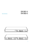
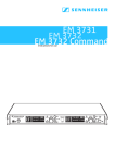
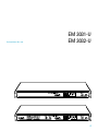
Instructions for use
EM 3031-U
EM 3032-U
27
Thank you for choosing Sennheiser!
You have made an excellent choice. This product will give you reliable and cost-effective ease of
operation over many years. All of Sennheiser’s professional expertise and more than fifty years of
experience have gone into the creation of this state-of-the-art product.
Please take a few moments to read these instructions carefully. We want you to enjoy your new
receiver quickly and to the full.
Chapter
Contents ............................................................................................................................. Page
1
Brief description, variants, special features ........................................................... 29
2
Connections and operating elements ..................................................................... 30
3
Noise reduction with HiDyn plus® ................................................................................................................................................. 32
4
Diversity reception .................................................................................................. 33
5
Assembly and mounting, assembly instructions ................................................... 34
6
Connection and mounting of remote antennæ ...................................................... 36
7
Switching the mains voltage / Mains connection .................................................. 37
8
Putting the receiver into operation ......................................................................... 38
9
Changing the receiving frequency ......................................................................... 39
10
Selection and combination of possible receiving frequencies ............................... 40
11
Reprogramming the receiving frequencies – no problem! ................................... 41
12
Display of frequency groups ................................................................................... 41
13
Power of the received radio signal ......................................................................... 32
14
Squelch (Muting), AF squelch ................................................................................ 32
15
Advanced muting function ..................................................................................... 43
16
Monitoring the sound signal, headphone connection .......................................... 44
17
Replacing a fuse ....................................................................................................... 45
18
Sennheiser transmitters report their battery status ............................................... 46
19
Suitable Sennheiser transmitters ............................................................................ 47
20
Error messages ........................................................................................................ 48
21
Error checklist ......................................................................................................... 48
22
Safety instructions ................................................................................................... 48
23
Recommended accessories ...................................................................................... 49
24
Technical data .......................................................................................................... 50
28
1
Brief description
With the EM 3031-U and EM 3032-U receivers, Sennheiser offers the professional user high
quality RF receivers with a high level of operational reliability and ease of use. The EM 3031-U
and EM 3032-U receivers together with the suitable hand-held and pocket transmitters permit
wireless transmission with studio quality sound. Due to further optimised PLL and microprocessor
technology and the Sennheiser patented HiDyn plus® noise reduction system, these transmission
systems surpass the signal-to-noise ratio and dynamic range of modern CD productions. The true
diversity technology of the EM 3031-U and EM 3032-U receivers ensures interference-free
transmission and minimises the drop-outs in the RF path.
Especially for small television studios and theatres, the simultaneous use of several EM 3031-U /
EM 3032-U receivers is an economical alternative to technically more sophisticated and therefore
more expensive multi-channel systems.
Variants
EM 3031-U:
Single-32-channel true diversitiy receiver
EM 3032-U:
Two-32-channel true diversitiy receiver
Note
EM 3031-U and EM 3032-U differ in the fact that the EM 3032-U contains two
complete true diversity receivers in a single 1 U rack housing. These two receivers
are powered by a common mains power supply unit and via a common pair of
antennæ (antenna splitter integrated).
This manual is therefore always restricted to the description of just one receiver,
the operation of the second receiver in the EM 3032-U is similar.
Special features
PLL microprocessor control, programmable
Sennheiser HiDyn plus® noise reduction system
High transmission reliability due to true diversity reception
Ease of use
“LOW BATT“ display for transmitter battery status
19" 1 U housing
Supply voltage for external antenna boosters
29
2
Connections and operating elements
Headphone socket 1/4 “ (6.3 mm) ø
Headphone volume control
Multi-function display panel
Buttons for selecting the receiving frequency
SET/storage button for channel programming
Changing the receiving frequency:
30
ON / OFF switch
Button Buttons , or Button for about 3 seconds
Fuse holder and mains voltage selection
2-pin IEC mains connector
Squelch control
Straw relief clamp for mains cable
Service interface (not used in normal operation)
AF output XLR-3, balanced
Control for AF output level at the XLR socket Antenna input B
Antenna input A
31
3
Noise reduction with HiDyn plus®
Progress you can hear:
This receiver is equipped with HiDyn plus®, the Sennheiser noise reduction system. HiDyn plus®
reduces interference from the RF Line. It increases the signal-to-noise ratio in wireless audio
transmission to up to 110 dB. The dynamic range of a CD is a maximum of 96 dB (16-bit transducer)
and is thus surpassed considerably.
HiDyn plus® is a wideband compander system which compresses the AF level on the transmitter
side in a ratio of 2:1 (related to dB), and expands it in an exactly the same way on the receiver side.
The optimisation of the dynamic range and the supporting effect of the control amplifier in the
transmitter effectively reduce modulation problems.
HiDyn plus® has been developed for use in high quality radiomicrophone systems.
Note
Only transmitters which are also equipped with HiDyn plus® can work perfectly in
combination with the EM 3031/3032 receiver. If this is not the case, the dynamic
range is drastically reduced, the transmission sounds blunt and flat. HiDyn plus®
can not be switched off on the EM 3031/3032 receiver.
32
AF-signal
receiver 1
4
AF-signal
electronic switching
from one signal to another
receiver 2
Diversity reception
The EM 3031/3032 receiver operates on the “true diversity” principle:
A receiving antenna receives not only the electromagnetic waves which reach it by a direct path,
but also the reflections of these waves which are created in the room by walls, windows, ceilings
and fittings. When these waves are superimposed, destructive interference occurs, which can also
be called “field strength gaps”. Repositioning the receiving antenna can bring a solution, provided
the transmitter remains in its original position. With mobile transmitters, however (which all
radiomicrophones are ), the “field strength gap“ will then occur with a different transmitter position.
These “field strength gaps“ can only be eliminated with true diversity receivers.
In true diversity, instead of one antenna and one receiver there are now two antennæ and two
receiver sections. The antennæ are spatially separated. By means of a comparison circuit, the
receiver section with the strongest RF signal is always switched to the common AF output. The
risk of the occurrence of “field strength gaps” in both antennæ at the same time is virtually
nonexistant.
The display panel of the receiver always shows whether the diversity channel switched is channel
A or channel B.
33
5
Assembly and mounting
Use as a stand-alone receiver
For use as a stand-alone receiver, it is recommended that the supplied telescopic antennæ are used.
They can be mounted quickly and easily to the rear of the receiver and are suitable for all applications
where – good reception conditions provided – a wireless transmission system is to be used without
a large amount of installation work.
To ensure that the receiver is securely mounted
on a surface on which it can not slip, four selfadhesive soft rubber feet are supplied. These feet
are stuck into the recesses on the lower side of
the receiver.
Ensure that the recesses are clean and free from
grease before mounting the feet.
N.B.
Do not use these feet if rack-mounting
the receiver.
34
Mounting the receiver into a rack
With the two rack mount “ears“ supplied, the receiver can be mounted into a 19" rack (1 U). The
rack mount “ears“ are screwed to the receiver on the left and right .
Note
If you wish to connect the antennæ to the front side, you must now pull the cables
of the GA 3030-AM antenna mount through the holes on the rack mount “ears“
before mouting the “ears“ .
The GA 3030-AM antenna mount (accessory, see chapter 23) allows the antennæ to be connected
to the front of the receiver, for example if the rear of the rack is closed.
Mount the antenna holders to the right and left to the handles of the receiver . The connection
cables, which are firmly fixed to the antenna holders, are connected to the antenna sockets on the
rear of the receiver.
Assembly instructions
Do not place receivers in direct proximity to digitally controlled devices!
Site the receivers as high as possible so that the receiving antennæ have a
“free line of sight” to the transmitter antennæ!
35
6
Connection and mounting of remote antennæ
If the receiver position is not the best antenna position for optimum reception, you can use remote
antennæ. These are available as accessories.
The best reception quality is obtained with the Sennheiser A12 AD-UHF active antenna. Antenna
and receiver can be connected with a RG 58 co-axial cable. Ready made up antenna cables from
Sennheiser are available as accessories with lengths of 1 m, 5 m and 10 m (see chapter 20)
Attention!
To supply the antenna booster integrated in the A12 AD-UHF active antenna, a
direct voltage (which can not be switched off) is output via the antenna sockets. If
you use antennæ from other manufacturers instead of the A12 AD-UHF, take into
account that these must be installed with direct voltage decoupling, i.e. isolated.
The output voltage supply is short circuit-proof, but an active antenna connected
to this supply increases the power consumption of the overall device.
Notes on mounting the antennæ (which absolutely must be adhered to)
Position antennæ in the same room in which the transmission takes place!
Maintain a minimum distance of 1 metre from metal objects (including walls of
reinforced concrete)!
Maintain a minimum distance of 1 metre between the receiving antennæ!
36
7
Switching the mains voltage
Before you plug the mains connector into the mains, please check first of all
that the receiver is set to the correct mains voltage!
You can switch the mains voltage by removing the fuse holder with the inserted fuse , turning
it through 180° and inserting it again , . The rated voltage set can now be seen at the top of
the fuse holder.
Mains connection
Insert the mains cable supplied into the socket on the receiver and pass the cable through the
traction relief .
Because of the traction relief, the cable can no longer slip out of socket and interrupt operation.
Note
A straw relief clamp is particularly important when the receiver is permanently
rack mounted. Inside the rack there are often a large number of cables - a straw
relief clamp bracket prevents the cables from pressing each other out.
37
8
Putting the receiver into operation
The receiver is switched on with the ON / OFF switch . Display panel is now lit up to show
that the receiver is switched on, and the last frequency set is shown (see chapter 10). The display
“MUTE“ (see chapter 13) is lit up . If a suitable transmitter is already operating on this frequency,
the display “MUTE“ is initially lit up for about 4 seconds. Then the display changes to “RF“ and
“DEV“ (RF level and modulation, see chapter 13), and the diversity branch in use is displayed
(see chapter 4).
Note
The ON / OFF switch works in the secondary circuit of the integrated mains
transformer, and thus only switches the low voltage side. By using a modern magnetic
core transformer, the power consumption of a EM 3031/3032 receiver of approx.
1
/2 Watt when switched off is extremely low. For larger installations with several
receivers, a complete mains disconnection can best be achieved by an additional
common ON / OFF switch.
The AF connection is via the socket on the rear. The control controls the AF signal
output level.
38
9
Changing the receiving frequency
To change the receiving frequency, please proceed with the following steps:
씰
Press button (“SET“). The text “FREQUENCY MHZ” in display panel begins to flash.
씰
With buttons (/) you can now select a different frequency. The display always jumps
to the next fixed frequency setting in the program. 8 channels are allocated to each range.
The 4 possible ranges are always shown by the display in display panel .
씰
Have you set the frequency correctly? Then press button (“SET“) again for about 3
seconds. Your entry is confirmed by the fact that the text “FREQUENCY MHZ” ceases to flash. At
the same time, “SŠł“ appears and the other displays in display panel go off briefly.
Only now does the receiver change to the new frequency, any existing RF link to a
transmitter on the previous frequency is interrupted.
You can discontinue your entry at any time by briefly pressing button (“SET“). The cancellation
is briefly confirmed on the display panel with “ESC“. The receiver switches back to normal
operation and the text “FREQUENCY MHZ” ceases to flash. The frequency to which the receiver was set
appears again.
After about 5 seconds, the receiver then automatically returns to normal operation if no entry has
been made during this period. Here, too, “ESC“ flashes briefly. You must then begin operation over
again.
39
10
Selection and combination of possible receiving frequencies
Each EM 3031 receiver (or each of the two EM 3032 receivers) can be programmed with a
maximum of 32 receiving frequencies within the switching bandwidth. These receiving frequencies
are divided into 4 groups.
Each group can contain from 0 to 8 receiving frequencies.
Pre-programming and group assignment is carried out by
the factory according to your specifications.
Possible specifications for frequency combinations:
Use of several receivers to make up a multi-channel system
With this frequency combination, the receiving frequencies are divided into groups such
that they can simultaneously be used within one group (or several groups) without causing
intermodulation interferences.
1 ... 8
1 ... 16
...
...
Use of receivers in different places
Here, a frequency group is assigned to a TV channel. If one or several receiving frequencies
are subject to interference (e.g. due to TV transmitters), please choose a frequency group
in a different TV channel.
40
Number of receiving frequencies
For ease of use, or if required by country-specific restrictions on the frequency usage, it is
also possible to program less than 32 receiving frequencies.
Your local Sennheiser distributor will be happy to help you
in the selection of your receiving frequencies.
11
Reprogramming the receiving frequencies – no problem!
If you wish – for whatever reason – to change your receiving frequencies, reprogramming, within
the limits of the receiver’s specifications, can be carried out without any problems by your local
Sennheiser service department.
12
Display of frequency groups
In the selection of receiving frequencies, the receiver goes through the four groups in succession.
The groups are shown on the display panel in display . Each additional illuminated dot represents
a further group:
1
2
3
4
41
13
Power of the received RF signal
In display panel , the power of the received RF signal in (µV) and the level control of the AF
signal – i.e. the modulation of the RF signal (in %) are shown. Both displays have an
overmodulation display. If the signal is too high, the text “PEAK“ lights up briefly. Short
overmodulation is not critical. Where longer overmodulation occurs, the modulation of the
corresponding transmitter must be reduced. For the AF signal, “peak hold” is also shown, which
means that short peaks remain visible for some time.
14
Squelch (Muting)
The EM 3031/3032 receiver is equipped with an adjustable squelch control which eliminates
annoying noise when the transmitters are switched on and off. It also suppresses sudden noise
when a transmitter leaves the reception area and there is no longer sufficient transmitter power
received by the receiver.
The squelch is adjusted on the rear of the receiver with control (“MUTING“). The adjustment
range is between 0 and about 100 µV. When the squelch is active, the text “MUTE“ is shown in
display panel .
AF squelch
The squelch also switches on when the selected radio channel is occupied by a wideband interference
signal such as that generated by lighting control systems. This prevents an interfering signal from
hindering reception even when the interfering signal has a high RF level. When control (“MUTING“) is set to position “0“, the AF squelch is also switched off.
42
AMF
15
AMF
Advanced muting function
This receiver also features AMF (Advanced Muting Function). This special electronic feature
comes into effect when an RF signal drops by about 50 dB in a short time. The reception is then
muted for 3 seconds. AMF thus suppresses the annoying switch-off click when a transmitter is
switched off. Because of the delay in switching on again, the PLL circuit of the transmitter has
enough time to adjust itself back to the corresponding transmission frequency.
Example
One possible area of use for AMF is the inaudible change of a hand-held transmitter.
If the battery of the first transmitter has run down (display “LOW BATT“ on the
receiver), a second transmitter is prepared on the same frequency: insert battery,
select transmission channel. Then the first transmitter is switched off, AMF switches
to mute and the second transmitter is immediately switched on. The PLL of
transmitter 2 stabilises itself, AMF switches on again. The whole procedure takes
place inaudibly in the background while AMF is switched to mute. Without AMF,
the switching off, switching on and stabilising of the transmission frequency would
have been audible in the form of possible crackles and whistling noises.
AMF can be switched off. As it is coupled with the setting of the normal squelch, its function is
cancelled if control (“MUTING“) is turned to position “0”.
43
16
Monitoring the sound signal, headphone connection
Socket on the EM 3031/3032 receiver can be used to monitor the sound signal received with
headphones. The headphone volume is adjusted with control .
Please use headphones with a 1/4 “ (6.3 mm) ø stereo jack plug. The sound signal itself is mono.
The Sennheiser HD 25 headphone is especially usefull for this purpose.
In order to judge the quality of the received sound signal even under unfavourable conditions (low
AF level in the transmitter) and with high ambient noise (e.g. on the stage), the sound signal at
socket can be monitored at an amplification of up to 30 dB compared with the LINE output.
For strong sound signals, however, this can distort the sound if control is turned to a high level.
In this case, turn control down until the distortion disappears. If the distortion remains, the
transmitter itself is overmodulated.
Volume up? – No!
First of all, the volume control should always be adjusted to the lowest volume
(by turning it anti-clockwise as far as possible). Then turn up the volume control gradually until you have reached the desired volume.
When people use headphones, they tend to choose a higher volume than with
loudspeakers. Listening at high volume levels for long periods can lead to permanent
hearing defects. Please protect your hearing, and as far as possible, check the sound
signal only briefly with the headphone.
44
17
Replacing a fuse
Disconnect the receiver completely from the mains! To do so, pull out the mains connector on
the receiver. You can then remove the fuse holder with the inserted fuse. Replace the fuse by a
new fuse with the same rating and switch on the receiver again. Make sure that you have inserted
the fuse holder in such a way that the receiver is operated with the correct mains power!
A faulty fuse should always be regarded as a warning. In most cases, the cause is harmless – a
short voltage surge or some similar cause has triggered the protective mechanism. When the fuse
has been replaced, the receiver works again.
If the replacement fuse also blows, please consult a specialist who can discover the cause. We
recommend you to contact your Sennheiser distributor or to send the receiver, with a precise
description of the trouble, to a Sennheiser service departement in your area. You can find the
address of your nearest service departement in the enclosed Service card or on the Internet under
“http://www.sennheiser.com”.
45
18
Sennheiser transmitters report their battery status
Sennheiser supplies hand-held and pocket transmitters which provide information on the available
transmitter battery status to the receiver. This information can be evaluated with the EM 3031 /
EM 3032 receivers.
When the battery capacity is so low that only a transmission time of about 20 to 30 minutes
remains, the text “LOW BATT“ flashes on the display panel .
You should now immediately replace the transmitter battery. The AMF (Advanced Muting Function)
in the EM 3031 / EM 3032 receiver helps you, as far as possible, to maintain the transmission
without noise (see chapter 15).
Notes
씰
The “LOW BATT“ display is reset by the mute function. Whenever the squelch is
activated in the receiver, the “LOW BATT“ display goes off and the evaluation of the
feedback from the transmitter starts over again.
씰
Under favourable reception conditions, the evaluation of the battery information
from the transmitter lasts about 10 – 20 seconds. However, it can be significantly
longer if reception is subject to interference from time to time. This time is then
also needed by the display in display panel in order to update the information
shown.
46
19
Suitable Sennheiser transmitters
For the optimum use of the excellent reception qualities of the EM 3031 / EM 3032 receivers,
Sennheiser offers hand-held and pocket transmitters in a variety of configurations:
Pocket transmitters:
SK 1063-U
BF 1083-U
SK 50-U
SK 250-U
(without display of battery condition)
(without display of battery condition)
(with display of battery condition)
(with display of battery condition)
Hand-held transmitters:
SKM 1072-U
SKM 3072-U
SKM 5000-U
(without display of battery condition)
(with display of battery condition)*
(with display of battery condition)
Information on the many possible combinations of Sennheiser products and their use in multichannel systems can be found in the planning brochure “Practical Applications in RF Technology”
which your Sennheiser distributor has in stock or will be pleased to order for you from Sennheiser.
Up to date information on Sennheiser products can also be found
on the Internet under “http://www.sennheiser.com”.
Sennheiser products are exclusively distributed through authorised Sennheiser distributors. We
regret that deliveries direct to private customers are not possible.
* available from approx. 4/97
47
20
Error messages
The display panel of the receiver is also used by the integrated microprocessor to display error
messages for service purposes. If you see error messages such as ERR ¡, ERR ™, ERR £ or ERR ¢, there
is a fault in the receiver unit which can only be corrected by your local Sennheiser service departement.
21
Error checklist
Error
Possible cause
Receiver does not work;
operating display dark
Receiver does not work;
operating display lit up
Fuse defective
Frequency of transmitter does not agree
with receiving frequency
•
Sound distorted
Switching threshold adjustment for
mute function too high
AF output signal adjusted too high. Input
of the connected mixing console or
amplifier is overmodulated
Transmission microphone overmodulated
(see corresponding section in the operating
manual of the transmitter)
Sound overlaid with background noise
Transmitter not sensitive enough; where
appropriate, switch transmitter sensitivity
from ”low” to ”high”
22
Safety instructions
Never open electronic devices! This must only be done by authorised personnel and is all
the more important for current-carrying units. If devices are opened by customers in breach
of this instruction, the warranty becomes null and void.
Always disconnect the unit from the main by removing the plug when you wish to change
connections or move the device to a different place.
Keep the system away from central heating radiators and electric heaters. Never expose it
to direct sunlight.
Use the system in dry rooms only.
Use a damp cloth for cleaning the device. Do not use any cleansing agents or solvents.
48
23
Recommended accessories
•
Antenna mount
GA 3030-AM
Cat. no. 04368
•
Active antenna
A 12 UHF
Cat. no. 04156
•
Ground plane antenna
GZA 1036-9
Cat. no. 02332
•
Co-axial cable, 1 m
GZL 1019 A1
Cat. no. 02324
•
Co-axial cable, 5 m
GZL 1019 A5
Cat. no. 02325
•
Co-axial cable, 10 m
GZL 1019 A10
Cat. no. 02326
•
•
BNC coupler
Active antenna splitter
acc. to customer specifications
GZV 1019A
Cat. no. 02368
AS-X
Cat. no. 03273
Monitoring headphone
HD 25
Cat. no. 02976
•
49
24
Technical data EM 3031 / EM 3032
RF characteristics
Frequency range
Receiver frequencies
Switching bandwidth
Frequency stability
Sensitivity (with HiDyn plus®)
Squelch treshold
Image rejection
Adjacent channel rejection
Intermodulation attenuation typ. 66 dB
Free field interference radiation 30 – 2000 MHz
Antenna input
Antenna input impedance
430–960 MHz
max. 32 in 4 groups,
pre-programmedto customer specifications
24 MHz
± 10 ppm (-10°C to +55°C)
typ: 5 µV for 90 dBAeff SNR
0 to 100 µV, adjustable
≥ 50 dB, typ. 65 dB
≥ 75 dB
(400 kHz/800 kHz)
> -57 dBm (2nW)
2 BNC sockets
50 Ω
AF characteristics
Modulation
Compander system
De-emphasis
Nominal/peak deviation
AF frequency response
AF outputs
wideband FM
Sennheiser HiDyn plus®
50 µs
± 40 kHz/± 56 kHz
45–20,000 Hz
LINE
MONITOR
AF output voltage at peak deviation
Amplification on monitor output
Source impedance of AF output
Signal-to-noise ratio
at 1 mVRF and peak deviation
THD at 1 kHz and nominal deviation
3-pin XLR, transformer balanced
1
/4 “ (6.3 mm) ø jack plug
(mono signal on stereo socket
Signal to L- and R-ring, sleeve earthed)
LINE: 0–5.6 V adjustable, ≥ 2 kΩ
MONITOR: 0–2.8 V adjustable, ≥ 600 Ω
30 dB
≤ 50 Ω (LINE at max. level)
120 dBA eff
116 dB external eff
106 dB CCIR peak
≤ 0.5%, typ. 0.25%
Overall device
Temperature range
Power supply
Power consumption EM 3031 / 3032
Dimensions (without rack mount “ears”)
Weight approx EM 3031 / 3032
50
-10°C to +55°C
115/230 V AC +10%/-15%
max 10 VA / max 15 VA
436 x 215 x 43 mm (19", 1 U)
3300 g / 4000 g
Änderungen vorbehalten
Subject to alterations
Sous réserve de modification
Con riserva di modifiche
Reservado el derecho a introducir modificaciones
Wijzigingen voorbehouden
Sennheiser electromic GmbH & Co. KG
D-30900 Wedemark
Telefon +49 (0)5130/600 0
Telefax +49 (0)5130/600 300
Printed in Germany
Publ. 02/97
58822 / A02