1
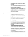
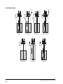
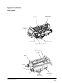
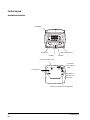
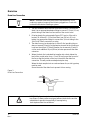
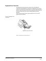
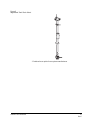
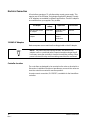
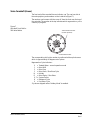
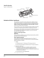
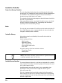
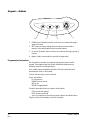
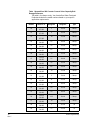
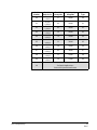
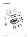
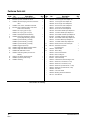
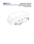
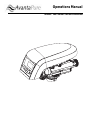
Operations Manual
Models: 269 Counter-Current Conditioner
Table of Contents
2
Rev C
How To Use This Manual
3
General Warnings And Safety Information
4
System Operation Cycle Functions
5
Equipment Installation
7
Valve Layout
7
Control Layout
8
Location Selection
9
Water Line Connection
10
Drain Line
12
Regenerant Line Connection
13
Overflow Line Connection
14
Electrical Connection
16
Valve Camshaft (Green)
17
Disinfection Of Water Conditioners
18
AvantaPure Controller
20
Display Icons
21
Keypad — Buttons
22
Things You Might Need to Know
23
Programming Overview
24
Level I Programming
24
Level II Programming
26
Level III Programming
31
Placing Conditioner Into Operation
32
Performa Exploded View
35
Performa Parts List
36
Troubleshooting
37
Table of Contents
How To Use This Manual
This installation manual is designed to guide the installer through the
process of installing and starting conditioners featuring the AvantaPure
controllers.
This manual is a reference and will not include every system installation
situation. The person installing this equipment should have:
Left Side
•
Training in the AvantaPure controllers and Autotrol brand valves
•
Knowledge of water conditioning and how to determine proper
control settings
•
Basic plumbing skills
•
The directional instructions "left" and “right" are determined by looking
at the front of the unit.
Right Side
Icons That Appear In This Manual
WARNING: Failure to follow this instruction can result in personal
injury or damage to the equipment.
NOTE: This will make the process easier if followed.
Introduction
Inspect the unit for damage or missing parts. Contact your supplier if any
discrepancies exist.
How To Use This Manual
3
Rev C
General Warnings And Safety Information
Electrical
There are no user-serviceable parts in the AC adapter, motor, or controller.
In the event of a failure, these should be replaced.
•
All electrical connections must be completed according to local codes.
•
Use only the power AC adapter that is supplied.
•
The power outlet must be grounded.
•
To disconnect power, unplug the AC adapter from its power source.
•
Do not use petroleum based lubricants such as vaseline, oils, or
hydrocarbon based lubricants. Use only 100% silicone lubricants.
•
All plastic connections should be hand tightened. Teflon tape may be
used on connections that do not use an O-ring seal. Do not use pliers
or pipe wrenches.
•
All plumbing must be completed according to local codes.
•
Soldering near the drain line should be done before connecting the
drain line to the valve. Excessive heat will cause interior damage to the
valve.
•
Observe drain line requirements.
•
Do not use lead-based solder for sweat solder connections.
•
The drain line must be a minimum of 1/2-inch diameter. Use
3/4-inch pipe if the backwash flow rate is greater than 7 GPM
(26.5 Lpm) or the pipe length is greater than 20 feet (6 m).
•
Do not support the weight of the system on the control valve fittings,
plumbing, or the bypass.
•
It is not recommended to use sealants on the threads. Use Teflon*
tape on the threads of the 1-inch NPT elbow, the drain line
connections, and other NPT threads.
Mechanical
*Teflon is a trademark of E.I. duPont de Nemours.
General
4
Rev C
•
Observe all warnings that appear in this manual.
•
Keep the media tank in the upright position. Do not turn upside down
or drop. Turning the tank upside down will cause media to enter the
valve.
•
Operating ambient temperature is between 34°F (1°C) and 120°F
(49°C).
•
Operating water temperature is between 34°F (1°F) and 100°F (38°C).
General Warnings And Safety Information
•
Working water pressure range is 20 to 120 psi (1.38 to 8.27 bar). In
Canada the acceptable working water pressure range is 20 to 100 psi
(1.38 to 6.89 bar).
•
Use only regenerant salts designed for water softening. Do not use ice
melting, block, or rock salts.
•
Follow state and local codes for water testing. Do not use water that is
microbiologically unsafe or of unknown quality.
•
When filling media tank, do not open water valve completely. Fill tank
slowly to prevent media from exiting the tank.
•
When installing the water connection (bypass or manifold) connect to
the plumbing system first. Allow heated parts to cool and cemented
parts to set before installing any plastic parts. Do not get primer or
solvent on O-rings, nuts, or the valve.
System Operation Cycle Functions
1. Service (Downflow)
Untreated water is directed down through the resin bed and up
through the riser tube. The water is conditioned as it passes through
the resin bed.
2.
Brine Refill
Water is directed down through the resin bed to the regenerant tank
at a controlled rate, to create brine for the next regeneration.
3.
Brine Preparation
The refill water is allowed to dissolve the salt and prepare brine.
4. Brine/Slow Rinse (Upflow)
The control directs water through the brine injector and brine is drawn
from the regenerant tank. The brine is then directed down the riser
tube up through the resin bed and up to the drain. The hardness ions
are displaced by sodium ions and are sent to the drain. The resin is
regenerated during the brine cycle. Brine draw is completed when the
air check closes.
5. Repressurized Cycle (Hard Water Bypass Flapper Open)
This cycle allows the air and water to hydraulically balance in the
valve before continuing the regeneration.
6. Backwash (Upflow)
The flow of water is reversed by the control valve and directed down
the riser tube and up through the resin bed. During the backwash
cycle, the bed is expanded and debris is flushed to the drain.
7. Fast Rinse (Downflow)
The control directs water down through the resin bed and up through
the riser tube to the drain. Any remaining brine residual is rinsed from
the resin bed.
System Operation Cycle Functions
5
Rev C
Cycle Water Flows
From Regenerant
Tank
To Regenerant
Tank
SERVICE
BRINE REFILL
REPRESSURIZE
6
Rev C
BRINE PREP
BACKWASH
BRINE/SLOW RINSE
FAST RINSE
System Operation Cycle Functions
Equipment Installation
Valve Layout
Valve Discs
One Piece Valve
Disc Spring
Control Module
Mount
Refill Controller
Injector and cap
Regenerant Tube Connection
Optical Sensor
Camshaft
Motor
Outlet
Drain
Inlet
Backwash
Drain Control
Equipment Installation
Injector Screen
Filter
7
Rev C
Control Layout
AvantaPure Controller
LCD Display
PM
MIN
LBS
KG
x100
Down Button
Manual Regen Button
Set Button
Up Button
Chlorine Generator Outlet
AC Adapter
(low voltage)
Input
For Future Use
Main Motor &
Optical Sensor
Connection
Turbine Input or Dry Contact Signal Input
8
Rev C
Control Layout
Location Selection
Location of a water treatment system is important. The following
conditions are required:
•
Level platform or floor
•
Room to access equipment for maintenance and adding regenerant
(salt) to tank.
•
Ambient temperatures over 34°F (1°C) and below 120°F (49°C).
•
Water pressure below 120 psi (8.27 bar) and above 20 psi
(1.4 bar).
•
In Canada the water pressure must be below 100 psi (6.89 bar).
•
Constant electrical supply to operate the controller.
•
Total minimum pipe run to water heater of ten feet (three meters) to
prevent backup of hot water into system.
•
Local drain for discharge as close as possible.
•
Water line connections with shutoff or bypass valves.
•
Must meet any local and state codes for site of installation.
•
Valve is designed for minor plumbing misalignments. Do not support
weight of system on the plumbing.
•
Be sure all soldered pipes are fully cooled before attaching plastic
valve to the plumbing.
Outdoor Locations
When the water conditioning system is installed outdoors, several items
must be considered.
Location Selection
•
Moisture — The valve and controller are rated for NEMA 3 locations.
Falling water should not affect performance.
The system is not designed to withstand extreme humidity or water
spray from below. Examples are: constant heavy mist, near corrosive
environment, upwards spray from sprinkler.
•
Direct Sunlight — The materials used will fade or discolor over time in
direct sunlight. The integrity of the materials will not degrade to cause
system failures.
If it is necessary to locate the conditioner in direct sunlight, a
protective outdoor cover (PN 1242287) over the valve and controller is
necessary. A valve skirt (PN 1242286) that provides further protection
is available.
•
Temperature — Extreme hot or cold temperatures will cause damage
to the valve or controller.
Freezing temperatures will freeze the water in the valve. This will cause
physical damage to the internal parts as well as the plumbing.
High temperatures will affect the controller. The display may become
unreadable but the controller should continue to function. When the
temperature drops down into normal operating limits the display will
9
Rev C
return to normal. A protective cover should assist with high
temperature applications.
•
Insects — The controller and valve have been designed to keep all but
the smallest insects out of the critical areas. Any holes in the top plate
can be covered with a metal foil ductwork tape. The top cover should
be installed securely in place.
•
Wind — The cover is designed to withstand a 30 mph
(48 Kph) wind when properly installed on the valve.
Water Line Connection
A bypass valve system should be installed on all water conditioning
systems. Bypass valves isolate the conditioner from the water system and
allow unconditioned water to be used. Service or routine maintenance
procedures may also require that the system is bypassed. The illustrations
below show the two common bypass methods.
Figure 1
Autotrol Series 1265
bypass for use with
Performa
In Bypass
Out
In
BY
PA S S
BY
Normal Operation
Out
In
PA S S
BY
BY
PA S S
PA S S
Water
Conditioner
Water
Conditioner
Figure 2
Typical Globe Valve Bypass
System
10
Rev C
Normal Operation
In Bypass
Water
Conditioner
Water
Water
Conditioner
Water
C di i
Water Line Connection
WARNING: The inlet water must be connected to the inlet port of the
valve. When replacing non-Autotrol valves, the inlet and outlet may be
reversed. It is also possible for the plumbing to be installed in an
opposite order.
Do not solder pipes with lead-based solder.
WARNING: Do not use tools to tighten plastic fittings. Over time,
stress may break the connections. When the 1265 bypass valve is used,
only hand tighten the nuts.
WARNING: Do not use petroleum grease on gaskets when connecting
bypass plumbing. Use only 100% silicone grease products when
installing any Autotrol brand valve. Non-silicone grease may cause
plastic components to fail over time.
WARNING: Several tube adapters are available to connect the valve
to the water plumbing. See Parts List.
Water Line Connection
11
Rev C
Drain Line
Drain Line Connection
NOTE: Standard commercial practices are expressed here. Local
codes may require changes to the following suggestions. Check with
local authorities before installing a system.
1. The unit should be above and not more than 20 feet (6.1 m) from the
drain. Use an appropriate adapter fitting to connect 1/2-inch (1.3 cm)
plastic tubing to the drain line connection of the control valve.
2. If the backwash flow rate exceeds 5 gpm (22.7 Lpm) or if the unit is
located 20-40 feet (6.1-12.2 m) from drain, use 3/4-inch (1.9 cm)
tubing. Use appropriate fittings to connect the 3/4-inch tubing to the
3/4-inch NPT drain connection on valve.
3. The drain line may be elevated up to 6 feet (1.8 m) providing the run
does not exceed 15 feet (4.6 m) and water pressure at the conditioner
is not less than 40 psi (2.76 bar). Elevation can increase by 2 feet (61
cm) for each additional 10 psi (.69 bar) of water pressure at the drain
connector.
4. Where the drain line is elevated but empties into a drain below the
level of the control valve, form a 7-inch (18-cm) loop at the far end of
the line so that the bottom of the loop is level with the drain line
connection. This will provide an adequate siphon trap.
Where the drain empties into an overhead sewer line, a sink-type trap
must be used.
Secure the end of the drain line to prevent it from moving.
Figure 3
Drain Line Connection
Right Way
Air Gap
Drain
WARNING: Never insert drain line directly into a drain, sewer line or
trap (Figure 3). Always allow an air gap between the drain line and the
wastewater to prevent the possibility of sewage being
back-siphoned into the conditioner.
12
Rev C
Drain Line
Regenerant Line Connection
The regenerant line from the tank connects to the valve. Make the
connections and hand tighten. Be sure that the regenerant line is secure
and free from air leaks. Even a small leak may cause the regenerant line to
drain out, and the conditioner will not draw regenerant from the tank. This
may also introduce air into the valve causing problems with valve
operation.
Ensure that pipe sealant (Teflon* tape) is applied to the 3/8-inch NPT
regenerant line connection.
Figure 4 Regenerant Line
Connection
Regenerant Line Connection
*Teflon is a trademark of E.I. duPont de Nemours.
Regenerant Line Connection
13
Rev C
Overflow Line Connection
In the event of a malfunction, the regenerant TANK OVERFLOW will direct
“overflow” to the drain instead of spilling on the floor. This fitting should be
on the side of the cabinet or regenerant tank. Most tank manufacturers
include a post for the tank overflow connector.
To connect the overflow line, locate hole on side of tank. Insert overflow
fitting into tank and tighten with plastic thumb nut and gasket as shown
(Figure 5). Attach length of 1/2-inch (1.3-cm) I.D. tubing (not supplied) to
fitting and run to drain. Do not elevate overflow line higher than overflow
fitting.
Do not tie into drain line of control unit. Overflow line must be a direct,
separate line from overflow fitting to drain, sewer or tub. Allow an air gap
as per drain line instructions.
Figure 5
Overflow Line Connection
Overflow Fitting
Drain Tubing
Secure hose in place
Air Gap
Drain
14
Rev C
Overflow Line Connection
Figure 6
Regenerant Tank Check Valve*
* Furnished as an option from system manufacturer.
Overflow Line Connection
15
Rev C
Electrical Connection
All controllers operate on 12-volt alternating current power supply. This
requires use of the GE Water Technologies supplied AC adapter. A variety
of AC adapters are available for different applications. These AC adapters
are available from your supplier. They include:
AC Adapter
Input
Voltage
Application
Part Number
Standard wall-mount
AC adapter
120V 60Hz
Standard indoor
application
1000811
Outdoor rated AC
adapter
120V 60Hz
UL listed for
outdoor
installations
1235448
120 VAC AC Adapters
Make sure power source matches the rating printed on the AC adapter.
NOTE: The power source should be constant. Be certain the AC
adapter is not on a switched outlet. Power interruptions longer than 8
hours may cause the controller to lose the time and day settings. When
power is restored, the day and time settings must then be re-entered.
Controller Location
The controllers are designed to be mounted on the valve or attached to a
flat surface. Installations that do not provide easy access to the valve can
have the controller mounted for remote operation.
A remote mount connection, PN 1256257, is available for the AvantaPure
controller.
16
Rev C
Electrical Connection
Valve Camshaft (Green)
The front end of the camshaft has an indicator cup. The cup has slots in
the outer periphery and numbers on the inside face (Figure 7).
The numbers can be seen with the cover off, from the front over the top of
the controller. The number at the top indicates which regeneration cycle is
currently in progress.
Figure 7
Camshaft Front End for
269 Valve Bodies
Treated Water Indicator
(normal operation)
Treated Water Slot
The corresponding slot for the number is positioned at the optical sensor
which is approximately 90 degrees out of phase.
Regeneration Cycle Indicators
0 =
1 =
2 =
3 =
*4 =
*5 =
6, 7 =
8 =
9 =
Treated Water - normal operation mode
Brine Refill
Brine Prep
Brine Draw / Slow Rinse Cycle
Holiday
Brine Empty / Slow Rinse
System Pause
Backwash Cycle
Fast Rinse Cycle
*Cycles are skipped unless "Holiday Mode" is enabled.
Valve Camshaft (Green)
17
Rev C
Valve Disc Operation
Figure 8 - Performa Valve
6 Rinse Drain
4 Outlet Valve
2 Bypass Valve
7 Backwash Drain Valves
3 Inlet Valve
5 Refill Valve
1 Regenerant Valve
Disinfection Of Water Conditioners
The materials of construction of the modern water conditioner will not
support bacterial growth, nor will these materials contaminate a water
supply. During normal use, a conditioner may become fouled with organic
matter, or in some cases with bacteria from the water supply. This may
result in an off-taste or odor in the water.
Some conditioners may need to be disinfected after installation and some
conditioners will require periodic disinfection during their normal life.
Depending upon the conditions of use, the style of conditioner, the type of
ion exchanger, and the disinfectant available, a choice can be made
among the following methods.
Sodium or Calcium Hypochlorite
Application
These materials are satisfactory for use with polystyrene resins, synthetic
gel zeolite, greensand and bentonites.
5.25% Sodium Hypochlorite
These solutions are available under trade names such as Clorox*. If
stronger solutions are used, such as those sold for commercial laundries,
adjust the dosage accordingly.
1. Dosage
A. Polystyrene resin; 1.2 fluid ounce (35.5 mL) per cubic foot.
B. Non-resinous exchangers; 0.8 fluid ounce (23.7 mL) per cubic foot.
2. Brine tank conditioners
A. Backwash the conditioner and add the required amount of
hypochlorite solution to the well of the regenerant tank. The
regenerant tank should have water in it to permit the solution to be
carried into the conditioner.
B. Proceed with the normal regeneration.
*Clorox is a trademark of the Clorox Company.
18
Rev C
Disinfection Of Water Conditioners
Calcium Hypochlorite
Calcium hypochlorite, 70% available chlorine, is available in several forms
including tablets and granules. These solid materials may be used directly
without dissolving before use.
1. Dosage
A. Two grains (approximately 0.1 ounce [3 mL]) per cubic foot.
2. Regenerant tank conditioners
A. Backwash the conditioner and add the required amount of
hypochlorite to the well of the regenerant tank. The regenerant tank
should have water in it to permit the chlorine solution to be carried
into the conditioner.
B. Proceed with the normal regeneration.
Disinfection Of Water Conditioners
19
Rev C
AvantaPure Controller
Power Loss Memory Retention
The controllers feature battery-free time and date retention during the
loss of power. This is designed to last a minimum of 8 hours depending on
the installation. The controller will continue to keep time and day in
dynamic memory while there is no AC power.
The controller will not track water usage on volumetric demand controls in
the event of a power failure.
All programmed parameters are stored in the static memory and will not
be lost in the event of a power failure. These settings are maintained
separately from the time and day settings.
Motor
The controller uses a standard 12-volt AC motor that works with either 50
Hz or 60 Hz. The same motor is used worldwide and does not need to be
changed for different power conditions.
Controller Memory
Information entered or calculated by the controller is stored in two
different ways.
A static memory will store:
Model number
Regenerant setting
Time of regeneration
Days between regeneration
Filter mode
A dynamic memory with 8 hour retention will store:
Current day of week
Running clock
NOTE: Water flow to the valve can be turned on or bypassed when the
controller is powered up for the first time.
Variable Reserve Function
The metered-demand volumetric controllers are designed with a variable
reserve feature. This feature automatically adjusts the reserve to the enduser’s water usage schedule.
A variable reserve saves salt and water by only regenerating when
absolutely necessary, and ensures enough soft water for typical
high-water usage days.
Each day of regeneration the controller reviews the last four weeks of
water usage for the same day of the week to determine if the remaining
capacity is adequate for the next day of the week. If not, it will initiate an
automatic regeneration.
20
Rev C
AvantaPure Controller
Display Icons
Figure 9
1
10
4
9
2
PM
MIN
LBS
KG
x100
3
4
5
7
6
8
NOTE: In normal operation and during programming, only a few of the
icons will actually be displayed.
1. Displays amount of conditioning capacity remaining.
2. "PM" indicates that the time displayed is between 12:00 noon and
12:00 midnight (there is no AM indicator). PM indicator is not used if
clock mode is set to 24-hour.
3. When "MIN" is displayed, the value entered is in minute increments.
4. When "LBS" is displayed, the value entered is in pounds.
5. When "Kg" is displayed, the value entered is in kilograms or kilograins.
6. Four digits used to display the time or program value. Also used for
error codes.
7. Colon flashes as part of the time display. Indicates normal operation.
8. X100 multiplier for large values.
9. Shows when water is flowing through the valve.
10. Banner display.
Display Icons
21
Rev C
Keypad — Buttons
1
2
4
3
1. DOWN arrow. Generally used to scroll down or increment through a
group of choices.
2. SET. Used to accept a setting that normally becomes stored in
memory. Also used together with the arrow buttons.
3. UP arrow. Generally used to scroll up or increment through a group of
choices.
4. Regen. Used to command the controller to regenerate.
Programming Conventions
The AvantaPure controller is programmed using the buttons on the
keypad. The programming instructions will be described two ways
whenever a section has keypad input.
First, a table shows simplified instructions. Second, text follows that
describes the action. In each table:
"Action" lists the event or action desired.
"Keys" are listed as:
UP for up arrow
DOWN for down arrow
SET for set
REGEN for regeneration
"Duration" describes how long a button is held down:
P/R for press and release
HOLD for press and hold
X sec for a number of seconds to press the button and hold it down
"Display" calls out the display icons that are visible.
22
Rev C
Keypad — Buttons
Things You Might Need to Know
Things You Might Need to Know
•
When the controller is first plugged in, it may display a flashing Err 3
and scrolling "Call Dealer for Service" message. This means that the
controller is rotating to the home position. The Err 3 will clear when the
control reaches the home position.
•
The preset default time of regeneration is 2:00 AM. If you want to
change it, see the Level II Programming section.
•
The controller can be programmed to regenerate on specific days of
the week. See Level II Programming section.
•
If electrical power is not available, the camshaft can be rotated
counterclockwise by hand if the motor is removed.
•
The AvantaPure controller sends commands to the motor for
camshaft movement. However, water pressure/flow are required
during the regeneration cycle for backwash, purge and refill, and brine
draw to actually take place.
•
Make sure control power source is plugged in. The transformer should
be connected to a non-switched power source.
23
Rev C
Programming Overview
The AvantaPure controller is designed to operate by setting the Time of
Day, Day of the Week, and the Hardness. The remaining settings are set at
the factory using a Model Number.
The controller menu has three levels:
Level I Basic — This level is easily accessed by the user. Only the Time of
Day, Day of Week and Time of Regeneration can be changed in Level I.
Level II Professional — This level allows the installer to change settings
such as hardness, capacity, and cycle times.
Level III History — This operation history and the program are viewable.
This information is used to troubleshoot and maintain the system.
NOTE: If a button is not pushed for thirty seconds, the controller
returns to normal operation mode.
NOTE: Any setting that is a time display will not show "AM" for times
between 12:00 midnight and 12:00 noon. "PM" is displayed to the right
of the time for times between 12:00 noon and 12:00 midnight. When
using the 24 hour clock "PM" is not displayed.
Level I Programming
Level I program parameters are those that can be accessed by the end
user by pressing the SET button. They include:
Time of Day
Day of Week
Time of Regeneration
•
Setting Time of Day
Upon initial start up of the controller, you will need to set the time of
day. The words “Time of Day” will scroll across the banner display and
the currently programmed time of day will be flashing below. If time is
not flashing, press the SET button. To change the time of day, press
and hold the UP or DOWN button until the correct time of day is
displayed. Press the SET button to accept the selection.
NOTE: When the controller is set up for a twelve hour clock a PM
indicator will illuminate when the displayed time is in the PM hours.
There is no AM indicator
24
Rev C
Programming Overview
•
Setting Day of Week
After setting the Time of Day the banner display will show the word
“Day” followed by an abbreviated day of the week.
SU = Sunday
MO = Monday
TU = Tuesday
WE = Wednesday
TH = Thursday
FR = Friday
SA = Saturday
Use the UP or DOWN arrow buttons to change the flashing day of
week. Press the SET button when the current day of week is flashing.
•
Setting Regeneration Time
The "Regeneration Time" is the setting which allows the programmer
to select the time of day that regeneration should occur. The words
“REGENERATION TIME” will scroll through the banner display. To
change the regeneration time press and hold the UP or DOWN button
until the desired regeneration time is displayed. Press SET to enter this
time into memory.
NOTE: When the controller is set up for a twelve hour clock a PM
indicator will illuminate when the displayed time is in the PM hours.
There is no indicator for the AM times.
Level I Programming
25
Rev C
Level II Programming
Level II program parameters are those parameters used to fine-tune a
conditioners operation. These are accessible by pressing and holding the
UP and DOWN buttons until the display goes blank. Then release the
buttons. Calendar Override is the first Level II parameter displayed. Level II
program parameters include:
269 Conditioner Operation Type
CALENDAR OVERRIDE
SALT AMOUNT
CAPACITY K GRAIN
HARDNESS GPG
SELECT LANGUAGE
CLOCK MODE
UNITS OF MEASURE
INJECTOR SELECTION*
BACKWASH
SLOW RINSE
FAST RINSE
OPERATION TYPE 269*
SERVICE INTERVAL
CHLORINE GENERATOR
*View only.
Level II parameters will, in almost all cases, be preset to meet your
configuration needs. The predefined system number will preprogram all of
the Level II parameters to the selected default values.
•
Setting the Calendar Override
Calendar Override allows the programmer to set the maximum days
between regenerations. A setting of 0 (zero) means the calendar
override is disabled. To change the calendar override, press the SET
button while the words “CALENDAR OVERRIDE" appear on the banner
display. The blinking digit can be changed to the desired numbers of
days. To lock in the parameter, press the SET button.
WARNING: Setting days between regeneration to zero will cause the
system to not regenerate. This setting is used for selecting regeneration
on specific days or to use with a remote regeneration input. See below.
NOTE: Regeneration on specific day is used to provide regeneration
when water demands are not steady. Example: If the weekdays have
low usage and the weekend is high, then regeneration every three days
will not meet the requirements.
The calendar override days between regeneration must be set to zero
to enable regeneration on specific days.
26
Rev C
Level II Programming
•
Viewing the Salt Amount
The salt amount is selected by tyour AvantaPure Water Treatment
Professional.
•
Setting Capacity
Softener Default Capacity Setting
The default capacity setting is accurately calculated when the model
number is entered by the factory. The capacity can be changed.
Contact your AvantaPure Water Treatment Professional before
adjusting the capacity setting. Default capacities are shown in Table 1.
NOTE: (Conditioners only) A different model number must be selected
to change the default capacity and salt dosage.
•
Setting the Hardness (conditioner only)
Hardness is set in grains per gallon (gpg) or parts per million (ppm) and
should be programmed to the total hardness level of the incoming
water supply. Press the SET button to make the display flash. Use the
UP and DOWN buttons to adjust the hardness setting. Press the SET
button when the desired setting has been reached.
•
Setting the Language
The controller is capable of displaying 6 different languages. They are
as follows:
1 = English
2 = Spanish
3 = French
4 = Italian
5 = Flemish
6 = German
Press the SET button and select the desired language using the UP or
DOWN buttons. Press the SET button to accept the selection.
•
Setting Clock Mode
The controller can be programmed to operate with a 12- or 24-hour
clock. Program the clock mode to "12" for a 12-hour clock or "24" for a
24-hour clock. When the controller is programmed as a 12-hour clock
the PM indicator will illuminate during the PM hours. There is no AM
indicator.
•
Setting Units of Measure
The controller can be programmed to operate in U.S. or Metric units.
Program the Units of Measure to 0 (zero) for U.S. units or 1 for Metric
units.
•
Viewing the Injector Type
The injector is selected by system model number at the factory.
Level II Programming
27
Rev C
Table 1 AvantaPure 269 Counter Current Valve Capacity/Salt
Dosage Reference
This table is for reference only. Your AvantaPure Water Treatment
Professional selects the model numbers based on your specific
application requirements.
Model
Number
40
41
42
43
44
45
46
47
48
49
50
51
52
53
54
55
56
57
58
59
28
Rev C
Tank Size
Resin Cu. Ft.
8 X 44
0.75 Ft3
8 X 44
0.75 Ft3
8 X 44
0.75 Ft3
9 X 48
1.00 Ft3
9 X 48
1.00 Ft3
9 X 48
1.00 Ft3
9 X 48
1.00 Ft3
10 X 40
1.00 Ft3
10 X 40
1.00 Ft3
10 X 40
1.00 Ft3
10 X 40
1.00 Ft3
10 X
1.25 Ft3
10 X
1.25 Ft3
10 X
1.25 Ft3
10 X 54
1.50 Ft3
10 X 54
1.50 Ft3
10 X 54
1.50 Ft3
10 X 54
1.50 Ft3
12 X 48
2.00 Ft3
12 X 48
2.00 Ft3
Total Salt
Dosage lbs
Total Capacity
Kilograins
Injector
Type
3
10,000
3 Bump
6
15,000
3 Bump
10
17,000
3 Bump
2.5
10,000
4 Bump
3.5
12,000
4 Bump
8.5
20,000
4 Bump
13
22,000
4 Bump
2.5
10,000
5 Bump
3.5
12,000
5 Bump
8.5
20,000
5 Bump
13
22,000
5 Bump
3
13,000
5 Bump
11
25,000
5 Bump
16
28,000
5 Bump
4.0
16,000
5 Bump
5.0
18,000
5 Bump
12.5
30,000
5 Bump
19
33,000
5 Bump
5
21,000
58
7.5
25,000
59
Level II Programming
Model
Number
60
61
62
63
64
65
66
67
68
69
99
Level II Programming
Tank Size
Resin Cu. Ft.
12 X 48
2.00 Ft3
13 X 54
2.50 Ft3
13 X 54
2.50 Ft3
13 X 54
2.50 Ft3
14 X 65
3.00 Ft3
14 X 65
3.00 Ft3
14 X 65
3.00 Ft3
14 X 65
3.50 Ft3
14 X 65
3.50 Ft3
14 X 65
3.50 Ft3
Total Salt
Dosage lbs
Total Capacity
Kilograins
Injector
Type
17
40,000
60
6.5
26,000
61
8.5
30,000
62
20
49,000
63
7.5
31,000
64
11
39,000
65
20
54,000
66
8.5
36,000
67
12
42,000
68
20
57,000
69
- For Special Applications Contact the System Manufacturer
29
Rev C
•
Adjusting the Cycle Times
The following cycle times are adjustable.
Cycle
Range
Slow Rinse
1 to 125 minutes
Backwash
1 to 50 minutes
Fast Rinse
1 to 30 minutes
Refill time does not appear as this cycle time is determined by the salt
setting.
The controller calculates the Slow Rinse default time based on injector
type, system size and salt dosage. The cycle times can be adjusted for
custom applications. Please contact your AvantaPure Water Treatment
Professional before attempting to adjust the Slow Rinse time.
•
Viewing Operation Type
This parameter displays the controller type and is preset at the
factory: 269 Counter current conditioner.
•
Setting the Service Interval
The service interval feature is an option that will allow the installer to
program the unit to ask for maintenance after a programmed
duration. The feature is programmed from 0 (zero) to 99 months. When
the programmed length of time has been reached the words "CALL
DEALER FOR SERVICE" will appear in the banner display to signal the
end user that regular maintenance may be required. If it is set to 0
(zero) the function is disabled. If you wish to enable this function
program the desired service interval duration.
•
Setting the Chlorine Generator/Salt Check (conditioner only)
The controller has the capability to produce a low level of chlorine
during the brine draw stage of regeneration. It can also sense if there
is any brine present during the time when brine draw is occurring. This
parameter can be adjusted to the following:
0 = Chlorine Generator with Salt Check disabled
1 = Salt Check only
2 = Chlorine Generator with Salt Check enabled
A chlorine generator refill control/cable kit, P/N 3001760, must be
installed for this function to work properly. After it is installed, select
the desired parameter and push SET to accept the selection.
30
Rev C
Level II Programming
Level III Programming
Historical information can be retrieved from the controller be pressing the
SET and DOWN buttons simultaneously, with the controller in the home
position. Release both buttons when the controller displays MODEL
NUMBER. Press the UP or DOWN buttons to navigate to each setting. The
readout will scroll across the top of the display and the value will be
displayed below the readout. Upon completing the initial programming
procedure the average daily usages will display the same value. These
values will changes as the unit logs water usage.
Scrolling Display Readout
MODEL NUMBERa
DAYS SINCE REGENERATION
PEAK FLOW RATE - DAY AND TIME
PEAK FLOW RATE GPMa
Range/Values
See Salt/Capacity Table on page 28
0 to 255 days
Language/Clock Mode Dependant
0 to 47 GPM
WATER TREATED TODAY GAL
0 to 65536 gal.
WATER SINCE REGENERATION GAL
0 to 65536 gal.
SUNDAY AVERAGE USAGE GAL
0 to 65536 gal.
MONDAY AVERAGE USAGE GAL
0 to 65536 gal.
TUESDAY AVERAGE USAGE GAL
0 to 65536 gal.
WEDNESDAY AVERAGE USAGE GAL
0 to 65536 gal.
THURSDAY AVERAGE USAGE GAL
0 to 65536 gal.
FRIDAY AVERAGE USAGE GAL
0 to 65536 gal.
SATURDAY AVERAGE USAGE GAL
0 to 65536 gal.
TOTAL WATER USED GAL X 100a
0 TO 999900 gal.a
TOTAL WATER USED GAL X 1000000a
MONTHS SINCE SERVICEa
0 to 42,940,000 gal.a
0 to 2184 monthsa
a. Bold text indicates that specific values can be reset. Press and hold the SET button for 5 seconds to reset
the value.
Level III Programming
31
Rev C
Placing Conditioner Into Operation
Conditioner Start-Up
After you have performed the previous initial power-up steps, you will
need to place the conditioner into operation. Follow these steps carefully,
as they differ from previous Autotrol valve instructions.
NOTE: The control valve can be started-up even if power is not yet
available to the controller. The valve must be connected to the water
supply. The motor can be unmounted from the valve, and the camshaft
can be indexed manually counterclockwise by hand. This will allow the
tank to be filled and allows regenerant draw to be tested.
Action
Key
Duration
Display
Display current
cycle
SET
5 Sec.
Current cycle
Advance to
next cycle
SET and UP
Press and
release
Next cycle
Cancel
regeneration
SET and UP
5 Sec.
Regeneration
canceled
1. Remove the cover from the valve. Removing the cover will allow you to
see that the camshaft is turning, and in which cycle the camshaft is
currently positioned.
2. With the supply water for the system still turned off, position the
bypass valve to the “not in bypass” (normal operation) position.
3. Press and release the REGEN button on the controller. The scrolling
text on the display will show "DELAYED REGENERATION". Press UP to
navigate to "IMMEDIATE REGENERATION".
4. Press and release SET to begin regeneration. The display will show
eight LEDs moving from left to right on the banner display indicating
that the motor is running. Additionally, the display will show the total
regeneration time remaining.
Pressing and holding SET when the motor has stopped displays the
cycle description and cycle time remaining.
5. Press and release SET and UP simultaneously to advance to each
cycle.
6. Advance the control to the Backwash. See below for the cycle
sequences.
32
Rev C
Placing Conditioner Into Operation
Function
Display Text (269)
Treated Water
AvantaPure (269)
Regeneration
Brine Tank Refill
Brine Prep
Brine Draw/Slow Rinse
Pause - Please Wait
Backwash
Fast Rinse
7. Fill the media tank with water.
A. While the controller is in cycle (Backwash), open the water supply
valve very slowly to approximately the 1/4 open position.
WARNING: If opened too rapidly or too far, media may be lost out of
the tank into the valve or the plumbing. In the ¼ open position, you
should hear air slowly escaping from the valve drain line.
B. When all of the air has been purged from the media tank (water
begins to flow steadily from the drain line), open the main supply
valve all of the way. This will purge the final air from the tank.
C. Allow water to run to drain until the water runs clear from the drain
line. This purges any refuse from the media bed.
D. Turn off the water supply and let the system stand for about five
minutes. This will allow any air trapped to escape from the tank.
8. Add water to the regenerant tank (initial fill) (conditioner only).
A. With a bucket or hose, add enough water to the regenerant tank to
cover the screen located at the end of the air check assembly at the
bottom of the regenerant tank.
If the tank has a salt platform in the bottom of the tank, add water
until the water level is approximately 1 inch (25 mm) above the
platform.
NOTE: We recommend that you do not put regenerant into the tank
until after the control valve has been put into operation. With no
regenerant in the tank, it is much easier to view water flow and motion
in the tank.
9. Advance the controller to the refill position to prime the line between
the regenerant tank and the valve (conditioner only). You must start
another regeneration to do this.
Placing Conditioner Into Operation
33
Rev C
A. Slowly open the main water supply valve again, to the fully open
position. Be sure not to open too rapidly as that would push the
media out of the media tank.
NOTE: As you advance through each cycle there will be a slight delay
before you can advance to the next cycle. There will be a pause after
the brine draw and slow rinse cycles (system pause). This cycle allows
the water/air pressure to equalize on each side of the valve discs before
moving on.
B. With the water supply completely open, when you arrive at the
brine tank refill cycle, the controller will direct water down through
the line to the regenerant tank. Let the water flow through the line
until all air bubbles have been purged from the line.
C. Do not let the water flow down the line to the tank for more than one
to two minutes, or the tank may overfill.
D. Simultaneously press and release the SET and UP buttons to
advance to the Brine Prep cycle. After the Brine Prep cycle is
reached, press the SET and UP buttons to advance to the Brine
Draw/Slow Rinse cycle.
10. Draw water from the regenerant tank.
A. With the controller in this position, check to see that the water in the
regenerant tank is being drawn out of the tank. The water level in
the tank should recede very slowly.
B. Observe the water being drawn from the regenerant tank for at
least three minutes. If the water level does not recede, or goes up,
refer to the Troubleshooting section.
11. If the water level is receding from the regenerant tank press the SET
and the UP buttons to advance the controller back to the treated
water position.
12. Finally, turn on a faucet plumbed after the water conditioner. Run the
faucet until the water runs clear.
34
Rev C
Placing Conditioner Into Operation
Performa Exploded View
4
19
7
6
7
11
5
3
16
8
13
2
17
12
1
9
10A
18
14
15
11
10B
20
Warning: Do not use the flow control ball with #10A.
Performa Exploded View
35
Rev C
Performa Parts List
Code
Part
No.
Description
Qty. Code
1
3001534 Valve Assembly w/o Flow Controls
1
2
1235338* Top Plate, AvantaPure Valves
1
3
1235339 Valve Disc Spring, One Piece, Performa
1
16
Part
No.
Description
Plumbing Adapter Kits:
1
1001606 3/4-inch Copper Tube Adapter Kit
1001670 1-inch Copper Tube Adapter Kit
Valve
1001608 22-mm Copper Tube Adapter Kit
4
1242282 Cover, Valve, AvantaPure Controller
1
1001613 3/4-inch CPVC Tube Adapter Kit
5
1237402* Cam, AvantaPure Valve, STD, Green
1
1001614 1-inch CPVC Tube Adapter Kit
6
Qty.
Drain Control Assembly:
1
1001615 25-mm CPVC Tube Adapter Kit
1000212 No. 10 (2.5 gpm; 9.5 Lpm)
1001769 3/4-inch NPT Plastic Pipe Adapter Kit
1000213 No. 12 (3.5 gpm; 13.2 Lpm)
1001603 1-inch NPT Plastic Pipe Adapter Kit
7
1235361 Motor/Optical Cable Assembly
1
1001604 3/4-inch BSPT Plastic Pipe Adapter Kit
8
1000226 Screen/Cap Assembly w/ O-Ring
1
1001605 1-inch BSPT Plastic Pipe Adapter Kit
9
Injector (High Efficiency) Options:
1001611 3/4-inch BSPT Brass Pipe Adapter Kit
1032980 Injector Assembly, (4 bumps)
1001610 1-inch NPT Brass Pipe Adapter Kit
1032982 Injector Assembly, (5 bumps)
1001612 1-inch BSPT Brass Pipe Adapter Kit
1032984 Injector Assembly, (6 bumps)
17
1235373 Module, Sensor, Photo Interrupter
1
1032985 Plugged Injector Cap
18
3001745 AvantaPure Controller
1
10A
1000222 Regenerant Refill Controller, No Ball
10B
1243510 Regenerant Refill Controller
1
19
1235446 Turbine Cable
(unprogrammed)
1
11
1030502 Ball, Refill Flow Control
20
1010154 Tank O-Ring
1
12
1002449 Drain Fitting Elbow (3/4-inch hose
13
1
*
*
1233187 Motor Locking Pin
1000811 AC Adapter, North American
1
*
3001760 Chlorine Generator Kit
14
1000269 Injector Cap with O-Ring
1
*
1033444 Turbine Assembly
15
1035622 Tank Ring
1
*
1239979 Cable Harness, Remote Regen 740F
barbed)
1033444 Internal Turbine Meter
*
1239711 Switch Kit, Front Mount, 0.1 amp
*
1239752 Switch Kit, Front Mount, 5 amp
*
1239753 Switch Kit, Top Plate Mount, 0.1 amp
*
1239754 Switch Kit, Top Plate Mount, 5 amp
*
1242286 Valve Skirt
*
1242287 Cover with Shield
*
1239760 Blending Valve Kit AvantaPure
*
1041174 Valve Disc Kit
*Not shown on drawing.
36
Rev C
Performa Parts List
Troubleshooting
AvantaPure Controller Troubleshooting
Problem
Possible Cause
Solution
ERR 1 is displayed.
Program settings have been corrupted.
Press any key and reset model number.
ERR 3 is displayed.
Controller does not know the position of
the camshaft. Camshaft should be
rotating to find Home position.
Wait for two minutes for the controller to
return to Home position. The hourglass
should be flashing on the display
indicating the motor is running.
Camshaft is not turning during ERR 3
display.
Check that motor is connected.
Verify that motor wire harness is
connected to motor and controller
module.
Verify that optical sensor is connected
and in place.
Verify that motor gear has engaged cam
gear.
If everything is connected, try replacing
in this order:
—Wire harness
—Motor
—Optical sensor
—Controller
If camshaft is turning for more than five
minutes to find Home position:
Verify that optical sensor is in place and
connected to wire.
Verify that camshaft is connected
appropriately.
Verify that no dirt or rubbish is clogging
any of the cam slots.
If motor continues to rotate indefinitely,
replace the following components in this
order:
—Wire harness
—Motor
—Optical sensor
—Controller
Power failure occurred.
Press SET to reset the time display.
Time of Day incorrect.
Troubleshooting
37
Rev C
System Troubleshooting
Problem
1. Brine tank
overflow.
Possible Cause
a. Uncontrolled brine refill flow rate.
b. Air leak in brine line to air check.
c. Drain control clogged with resin
or other debris.
2. Flowing or
dripping water at
drain or brine line
after
regeneration.
3. Hard water
leakage after
regeneration.
4. Control will not
draw brine.
Solution
a. Remove brine control to clean ball and seat.
b. Check all connections in brine line for leaks.
Refer to instructions.
c. Clean drain control.
a. Valve stem return spring weak.
b. Debris is preventing valve disc
from closing.
a. Replace spring. (Contact dealer.)
b. Remove debris.
a. Improper regeneration.
a. Repeat regeneration after making certain
correct regenerant dosage was set.
b. Replace bypass valve. (Contact dealer.)
c. Replace O-ring. (Contact dealer.)
b. Leaking of external bypass valve.
c. O-ring around riser pipe
damaged.
d. Incorrect capacity.
a. Low water pressure.
b.
c.
d.
e.
Restricted drain line.
Injector plugged.
Injector defective.
Valve disc 2 and/or 3 not closed.
f.
Air check valve prematurely
closed.
d. Verify appropriate regenerant amount and
system capacity. (Contact dealer.)
a. Make correct setting according to
instructions.
b. Remove restriction.
c. Clean injector and screen.
d. Replace injector and cap. (Contact dealer.)
e. Remove foreign matter from disc and check
disc for closing by pushing in on stem.
Replace if needed. (Contact dealer.)
f. Put control momentarily into brine refill.
Replace or repair air check if needed.
(Contact dealer.)
a. Connect power.
5. Control will not
regenerate
automatically.
a. AC adapter or motor not
connected.
b. Defective motor.
6. Control
regenerates at
wrong time of
day.
7. Valve will not
draw brine.
a. Controller set incorrectly.
a. Correct time setting according to
instructions.
a.
b.
c.
d.
e.
a.
b.
c.
d.
e.
8. System using
more or less salt
than regenerant
setting.
a. Foreign matter in valve causing
incorrect flow rates.
38
Rev C
Low water pressure.
Restricted drain line.
Injector plugged.
Injector defective.
Air check valve closes
prematurely on brine pickup
tube.
b. Replace motor. (Contact dealer.)
Set pump to maintain 20 psi at softener.
Change drain to remove restriction.
Clean injector and screen.
Replace injector. (Contact dealer.)
Put control momentarily into brine/slow
rinse. Replace or repair air check if needed.
(Contact dealer.)
a. Remove brine control and flush out foreign
matter. Advance control to brine/slow rinse,
to clean valve (after so doing position
control to "fast rinse” to remove regenerant
from tank).
Troubleshooting
9. Intermittent or
irregular
regenerant draw.
10. No conditioned
water after
regeneration.
a. Low water pressure.
b. Defective injector.
a. Set pump to maintain 20 psi at conditioner.
b. Replace injector. (Contact dealer.)
a. No regenerant in regenerant
tank.
b. Injector plugged.
c. Air check valve closes
prematurely.
a. Add regenerant to regenerant tank.
11. Backwashes or
purges at
excessively low
or high rate.
a. Incorrect drain controller used.
a. Replace with correct size controller. (Contact
dealer.)
b. Remove drain controller and clean ball and
seat.
a. Shift bypass valve to not-in-bypass position.
b. Fully insert probe into meter housing.
12. No water flow
display when
water is flowing.
13. Run out of
conditioned
water between
regenerations.
b. Foreign matter affecting valve
operation.
a. Bypass valve in bypass.
b. Meter probe disconnected or not
fully connected to meter
housing.
c. Restricted meter turbine rotation
due to foreign material in meter.
a. Improper regeneration.
b. Incorrect regenerant setting.
c. Incorrect hardness or capacity
settings.
d. Water hardness has increased.
e. Restricted meter turbine rotation
due to foreign material in meter.
14. Regenerant tank
overflow.
Troubleshooting
a. Regenerant valve disc 1 being
held open by foreign matter.
b. Valve disc 2 not closed during
regenerant draw causing brine
refill.
c. Air leak in regenerant line to air
check.
d. Improper drain control for
injector.
e. Drain control clogged with resin
or other debris.
b. Clean injector and screen.
c. Put control momentarily into brine/slow
rinse. Replace or repair air check if needed.
(Contact dealer.)
c. Remove meter housing, free up turbine and
flush with clean water. Turbine should spin
freely. If not, replace meter. (Contact dealer.)
a. Repeat regeneration, making certain that
correct regenerant dosage is used.
b. Set P6 to proper level. See salt setting chart.
c. Set to correct values. See Programming
section.
d. Set hardness to new value. See
Programming section.
e. Remove meter housing, free up turbine and
flush with clean water. Turbine should spin
freely; if not, replace meter. (Contact dealer.)
a. Manually operate valve stem to flush away
obstruction.
b. Flush out foreign matter holding disc open
by manually operating valve stem.
c. Check all connections in regenerant line for
leaks. Refer to instructions.
d. Too small of a drain control with a larger
injector will reduce draw rates.
e. Clean drain control.
39
Rev C
40
Rev C
Troubleshooting
VIEWING AND SELECTING MODEL NUMBERS
AvantaPure 269 Counter Current Valve
Capacity/Salt Dosage Reference
Model number selection must match the tank size and resin volume of the system. Model number
determines salt dosage and capacity. A model number is assigned to each salt dosage for each
system size. Entering Level III programming and following the procedure listed below can change
model Number/Salt Dosage:
Viewing the Model Number
Press and hold the SET and DOWN buttons simultaneously until the display blanks out. Release
buttons.
The Model Number will be displayed. Proceed to the next step to change the Model Number. Note: The
control will revert back to the service display if no buttons are pushed within 30 seconds
To Change The Model Number
Press and hold the SET button until 0 is displayed
Release button.
A flashing 11 will now be displayed on the screen, which is a default model number.
Press the UP or DOWN button until the desired model number is displayed. See Table 1 AvantaPure
269 Counter Current Valve Capacity/Salt Dosage Reference in Level II programming section. *
Press and release the SET button to save the desired model number.
Time of day will scroll and time will be flashing.
Set Time of Day
Press the UP or DOWN button to set to the current time of day
Press the SET button to save setting.
Scroll will display DAY.
Day of the Week
Press UP or DOWN button to set to the current day of week.
Press and release SET button to save setting.
Regeneration Time will scroll, Time of Regeneration will be flashing.
To Change Time of Regeneration
Press the UP or DOWN button to set to the desired time of regeneration needed.
Press and release the SET button to save setting.
*The Model Number setting is very important. The AvantaPure controller software includes additional
Model Numbers that operate other AvantaPure valve types. If the Model number is set incorrectly an
ERROR 3 could be displayed in when advancing the valve through the regeneration cycles, and the
valve will not function properly. The control Model Number must be selected from Table 1 in this
service manual.
VIEWING AND SELECTING MODEL NUMBERS
43
Rev C
© Copyright 2006 General Electric Company
Printed in USA P/N 3001122 Rev. C