1
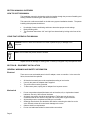
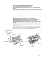
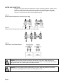
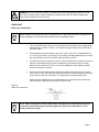
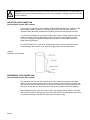
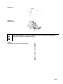
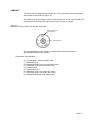
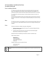
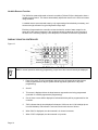
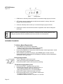
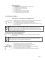
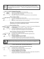
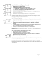
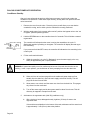
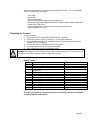
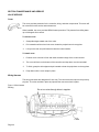
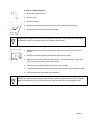
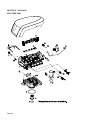
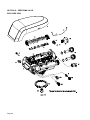
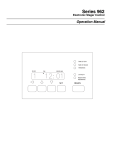
Owners Manual
740/760 Control
255/Performa Series
For Sales & Service questions
please contact your dealer:
SECTION A-MANUAL OVERVIEW
HOW TO USE THIS MANUAL
This installation manual is designed to guide the installer through the process of installing and
starting conditioners featuring the 700 Series controllers.
This manual is a reference and will not include every system installation situation. The person
installing this equipment should have:
•
•
•
Knowledge of water conditioning and how to determine proper control settings
Basic plumbing skills
The directional instructions “left” and “right” are determined by looking at the front of the
unit.
ICONS THAT APPEAR IN THIS MANUAL
WARNING: Failure to follow this instruction can result in personal injury or damage to the
equipment.
NOTE: This will make the process easier if followed.
Inspect the unit for damage or missing parts. Contact your supplier if any discrepancies exist.
SECTION B – EQUIPMENT INSTALLATION
GENERAL WARNINGS AND SAFETY INFORMATION
Electrical
There are no user-serviceable parts in the AC adapter, motor or controller. In the event of a
failure, these should be replaced.
•
•
•
•
All electrical connections must be completed according to local codes.
Use only the power AC adapter that is supplied.
The power outlet must be grounded.
To disconnect power, unplug the AC adapter from its power source.
•
Do not use petroleum based lubricants such as Vaseline, oils, or hydrocarbon based
lubricants. Use only 100% silicone lubricants.
All plastic connections should be hand tightened. Teflon tape may be used on
connections that do not use an O-ring seal. Do not use pliers or pipe wrenches.
All plumbing must be completed according to local codes.
Soldering near the drain line should be done before connecting the drain line to the
valve. Excessive heat will cause interior damage to the valve.
Observe drain line requirements.
Do not use lead-based solder for sweat solder connections.
Mechanical
•
•
•
•
•
Page 2
•
The drain line must be a minimum of 1/2-inch diameter. Use
3/4-inch pipe if the backwash flow rate is greater than 7 GPM
(26.5 Lpm) or the pipe length is greater than 20 feet (6 m).
Do not support the weight of the system on the control valve fittings, plumbing, or the
bypass.
It is not recommended to use sealants on the threads. Use Teflon* tape on the threads of
the 1-inch NPT elbow, the drain line connections, and other NPT threads.
•
•
*Teflon is a trademark of E.I. duPont de Nemours.
General
•
•
Observe all warnings that appear in this manual.
Keep the media tank in the upright position. Do not turn upside down or drop. Turning the
tank upside down will cause media to enter the valve.
Operating ambient temperature is between 34°F (1°C) and 120°F (49°C).
Operating water temperature is between 34°F (1°F) and 100°F (38°C).
Working water pressure range is 20 to 120 psi (1.38 to 8.27 bar). In Canada the
acceptable working water pressure range is 20 to 100 psi (1.38 to 6.89 bar).
Use only regenerant salts designed for water softening. Do not use ice melting, block, or
rock salts.
Follow state and local codes for water testing. Do not use water that is microbiologically
unsafe or of unknown quality without adequate disinfection before or after the system.
When filling media tank, do not open water valve completely. Fill tank slowly to prevent
media from exiting the tank.
When installing the water connection (bypass or manifold) connect to the plumbing
system first. Allow heated parts to cool and cemented parts to set before installing any
plastic parts. Do not get primer or solvent on O-rings, nuts, or the valve.
•
•
•
•
•
•
•
VALVE FEATURES
Figure 1
255 Valve Identification
Control Module
Mount
One Piece Valve
Disc Spring
Optical Sensor
Valve Discs
Camshaft
Refill Controller
Motor
Injector and Cap
Manifold
Connection
Outlet
Injector
Screen Filter
Drain
Check Ball
Inlet
Air Check
Regenerant Tank
Tube Connection
Locking Bar
Backwash
Drain Control
Page 3
Figure 2
Performa Valve Identification
Camshaft
Motor
Valve Discs
One Piece Valve
Disc Spring
Optical Sensor
Control Module
Mount
Outlet
Drain
Injector Screen
Filter
Inlet
Backwash
Drain Control
Refill Controller
Injector and cap
Regenerant Tube Connection
Figure 3
Controller Identification
LOCATION SELECTION
Location of a water treatment system is important. The following conditions are required:
•
•
•
•
•
•
•
•
•
•
•
•
Page 4
Level platform or floor.
Room to access equipment for maintenance and adding regenerant (salt) to tank.
Ambient temperatures over 34°F (1°C) and below 120°F (49°C).
Water pressure below 120 psi (8.27 bar) and above 20 psi
(1.4 bar).
In Canada the water pressure must be below 100 psi (6.89 bar).
Constant electrical supply to operate the controller.
Total minimum pipe run to water heater of ten feet (three meters) to prevent backup of
hot water into system.
Local drain for discharge as close as possible.
Water line connections with shutoff or bypass valves.
Must meet any local and state codes for site of installation.
Valve is designed for minor plumbing misalignments. Do not support weight of system on
the plumbing.
Be sure all soldered pipes are fully cooled before attaching plastic valve to the plumbing.
OUTDOOR LOCATIONS
When the water conditioning system is installed outdoors, several items must be considered.
•
•
•
•
•
Moisture — The valve and 700 controller are rated for NEMA 3 locations. Falling water
should not affect performance.
The system is not designed to withstand extreme humidity or water spray from below.
Examples are: constant heavy mist, near corrosive environment, upwards spray from
sprinkler.
Direct Sunlight — The materials used will fade or discolor over time in direct sunlight.
The integrity of the materials will not degrade to cause system failures.
If it is necessary to locate the conditioner in direct sunlight, a protective outdoor cover
over the valve and controller is necessary.
Temperature — Extreme hot or cold temperatures will cause damage to the valve or
controller.
Freezing temperatures will freeze the water in the valve. This will cause physical damage
to the internal parts as well as the plumbing.
High temperatures will affect the controller. The display may become unreadable but the
controller should continue to function. When the temperature drops down into normal
operating limits the display will return to normal. A protective cover should assist with
high temperature applications.
Insects — The controller and valve have been designed to keep all but the smallest
insects out of the critical areas. Any holes in the top plate can be covered with a metal
foil ductwork tape. The top cover should be installed securely in place.
Wind — The 700 Series cover is designed to withstand a 30 mph
(48 Kph) wind when properly installed on the valve.
Page 5
WATER LINE CONNECTION
A bypass valve system should be installed on all water conditioning systems. Bypass valves
isolate the conditioner from the water system and allow unconditioned water to be used.
Service or routine maintenance procedures may also require that the system is bypassed.
Figures 4, 5, and 6 show the three common bypass methods.
Figure 4
Autotrol Series 256 bypass for use with 255 valve body
In
Out
In
Out
Figure 5
Autotrol Series 1265 bypass for use with Performa and 1100 valve bodies
In
Out
In
Out
Figure 6
Typical Globe Valve Bypass System
WARNING: The inlet water must be connected to the inlet port of the valve. When replacing nonAutotrol valves, the inlet and outlet may be reversed. It is also possible for the plumbing to be installed
in an opposite order. Do not solder pipes with lead-based solder.
WARNING: Do not use tools to tighten plastic fittings. Over time, stress may break the connections.
When the 1265 or 256 bypass valve is used, only hand tighten the nuts.
Page 6
WARNING: Do not use petroleum grease on gaskets when connecting bypass plumbing. Use only
100% silicone grease products when installing any plastic brand valve. Non-silicone grease may
cause plastic components to fail over time.
DRAIN LINE
Drain Line Connection
NOTE: Standard commercial practices are expressed here. Local codes may require changes to the
following suggestions. Check with local authorities before installing a system.
1.
The unit should be above and not more than 20 feet from the drain. Use an appropriate
adapter fitting to connect 1/2-inch (1.3 cm) plastic tubing to the drain line connection of
the control valve.
2.
If the backwash flow rate exceeds 5 gpm (22.7 Lpm) or if the unit is located 20-40 feet
(6.1-12.2 m) from drain, use 3/4-inch (1.9 cm) tubing. Use appropriate fittings to connect
the 3/4-inch tubing to the 3/4-inch NPT drain connection on valve.
3.
The drain line may be elevated up to 6 feet (1.8 m) providing the run does not exceed 15
feet (4.6 m) and water pressure at the conditioner is not less than 40 psi (2.76 bar).
Elevation can increase by 2 feet (61 cm) for each additional 10 psi (.69 bar) of water
pressure at the drain connector.
4.
Where the drain line is elevated but empties into a drain below the level of the control
valve, form a 7-inch (18-cm) loop at the far end of the line so that the bottom of the loop
is level with the drain line connection. This will provide an adequate siphon trap.
Where the drain empties into an overhead sewer line, a sink-type trap must be used.
Secure the end of the drain line to prevent it from moving.
Figure 8
Drain Line Connection
NOTE: Waste connections or drain outlets shall be designed and constructed to provide for
connection to the sanitary waste system through an air gap of 2 pipe diameters or 1 inch
(25 mm) whichever is larger. .
Page 7
WARNING: Never insert drain line directly into a drain, sewer line or trap (Figure 8). Always allow an air
gap between the drain line and the wastewater to prevent the possibility of sewage being back-siphoned
into the conditioner.
OVERFLOW LINE CONNECTION
(not used with 3-cycle filter system)
In the event of a malfunction, the regenerant TANK OVERFLOW will direct “overflow” to the
drain instead of spilling on the floor. This fitting should be on the side of the cabinet or
regenerant tank. Most tank manufacturers include a post for the tank overflow connector.
To connect the overflow line, locate hole on side of tank. Insert overflow fitting into tank and
tighten with plastic thumb nut and gasket as shown (Figure 9). Attach length of 1/2-inch
(1.3-cm) I.D. tubing (not supplied) to fitting and run to drain. Do not elevate overflow line
higher than overflow fitting.
Do not tie into drain line of control unit. Overflow line must be a direct, separate line from
overflow fitting to drain, sewer or tub. Allow an air gap as per drain line instructions.
Figure 9
Overflow Line Connection
REGENERANT LINE CONNECTION
(not used with 3-cycle filter system)
The regenerant line from the tank connects to the valve. Make the connections and hand
tighten. Be sure that the regenerant line is secure and free from air leaks. Even a small leak
may cause the regenerant line to drain out, and the conditioner will not draw regenerant from
the tank. This may also introduce air into the valve causing problems with valve operation.
Most installations utilize a tank check valve. This is not necessary when using the 255 valve
with the built-in aircheck. Using a tank check valve with the 255 valve with aircheck will result
in premature checking of the aircheck valve, before the tank is empty.
Page 8
Figure 10A
Air Check for 255 Valve
Figure 10B
Performa Valve
Regenerant Line Connection
NOTE: When installing a 3-cycle filter (253,263, or 273 valve) use a cap on the regenerant line
connection to prevent water seepage from the port.
Figure 11
Regenerant Tank Check Valve (not provided)
Page 9
ELECTRICAL CONNECTION
All 700 Series controllers operate on 12-volt alternating current power supply. This requires
use of the supplied AC adapter. A variety of AC adapters are available for different
applications. These AC adapters are available from your supplier. They include:
AC Adapter
Standard wall-mount
AC adapter
Outdoor rated AC adapter
Input Voltage
120V 60Hz
International option
AC adapters
Varies based on
country
120V 60Hz
Application
Standard indoor
application
UL listed for outdoor
installations
Standard indoor
application
Part Number
1000811
1235448
See Parts Lists
Section
100 VAC, 120 VAC and 230 VAC AC Adapters:
Make sure power source matches the rating printed on the AC adapter.
NOTE: The power source should be constant. Be certain the AC adapter is not on a switched outlet.
Power interruptions longer than 8 hours may cause the controller to lose the time and day settings.
When power is restored, the day and time settings must then be re-entered.
The 700 Series controller is available in two power configurations. The North America
controller operates on 60 Hz. If the incoming power is 50 Hz, the "North American" controller
will not function. The error code "ERR 2" will show on the display.
The "World" controller will sense the input power as 50 or 60 Hz and operate accordingly.
Controller Location
The 700 Series controllers are designed to be mounted on the valve or attached to a flat
surface. Installations that do not provide easy access to the valve can have the controller
mounted for remote operation.
To enable mounting for remote operation the wiring harness can be extended up to 50 feet
(15 m) with a minimum 22 gauge wire.
Page 10
CAMSHAFT
The front end of the camshaft has an indicator cup. The cup has slots in the outer periphery
and numbers on the inside face (Figure 12).
The numbers can be seen with the cover off, from the front over the top of the controller. The
number at the top indicates which regeneration cycle is currently in progress.
Figure 12
Camshaft Front End for 255, 263, and 268 valve bodies
Treated Water Indicator
(normal operation)
Treated Water Slot
The corresponding slot for the number is positioned at the optical sensor which is
approximately 90 degrees out of phase.
Regeneration Cycle Indicators
C0 = Treated Water - normal operation mode
C1 = Backwash Cycle
C2 = Regenerant Draw Cycle (not used in filter mode)
C3 = Slow Rinse Cycle (not used in filter mode)
C4 = System Pause
C5 = Fast Rinse Cycle 1
C6 = Backwash Cycle 2 (not used in filter mode)
C7 = Fast Rinse Cycle 2 (not used in filter mode)
C8 = Regenerant Refill (not used in filter mode)
Page 11
SECTION C-SYSTEM DISINFECTION
DISINFECTION OF WATER CONDITIONERS
The materials of construction of the modern water conditioner will not support bacterial growth,
nor will these materials contaminate a water supply. During normal use, a conditioner may
become fouled with organic matter, or in some cases with bacteria from the water supply. This
may result in an off-taste or odor in the water.
Some conditioners may need to be disinfected after installation and some conditioners will
require periodic disinfection during their normal life.
Depending upon the conditions of use, the style of conditioner, the type of ion exchanger, and
the disinfectant available, a choice can be made among the following methods.
Sodium or Calcium Hypochlorite
Application
These materials are satisfactory for use with polystyrene resins, synthetic gel zeolite,
greensand and bentonites.
5.25% Sodium Hypochlorite
These solutions are available under trade names such as Clorox*. If stronger solutions are
used, such as those sold for commercial laundries, adjust the dosage accordingly.
1.
2.
Dosage
A.
Polystyrene resin; 1.2 fluid ounce (35.5 ml) per cubic foot.
B.
Non-resinous exchangers; 0.8 fluid ounce (23.7 ml) per cubic foot.
Brine tank conditioners
A.
B.
Backwash the conditioner and add the required amount of hypochlorite solution to
the well or the regenerant tank. The regenerant tank should have water in it to permit
the solution to be carried into the conditioner.
Proceeded with the normal regeneration.
*Clorox is a trademark of the Clorox Company.
Calcium Hypochlorite
Calcium hypochlorite, 70% available chlorine, is available in several forms including tablets
and granules. These solid materials may be used directly without dissolving before use.
1.
Dosage
A.
2.
Page 12
Two grains (approximately 0.1 ounce [3 ml]) per cubic foot.
Regenerant tank conditioners
A.
Backwash the conditioner and add the required amount of hypochlorite to the well of
the regenerant tank. The regenerant tank should have water in it to permit the
chlorine solution to be carried into the conditioner.
B.
Proceed with the normal regeneration.
SECTION D-GENERAL 700 SERIES INSTRUCTIONS
700 SERIES CONTROLLER
Power Loss Memory Retention
The 700 series controllers feature battery-free time and date retention during the loss of
power. This is designed to last a minimum of 8 hours depending on the installation. The
controller will continue to keep time and day in dynamic memory while there is no AC power.
The controller will not track water usage on volumetric demand controls in the event of a
power failure.
All programmed parameters are stored in the 700 Series static memory and will not be lost in
the event of a power failure. These settings are maintained separately from the time and day
settings.
Motor
The 700 Series controller uses a standard 12-volt AC motor that works with either 50 Hz or 60
Hz. The same motor is used worldwide and does not need to be changed for different power
conditions.
Power
700 Series controllers are available in two power configurations:
1.
The North American model requires 60 Hz input. The controller will display USA units
when power is first applied.
2.
The World model accepts either 60 or 50 Hz input and will automatically adjust
measurement units when power is first applied.
Information entered or calculated by the controller is stored in two different ways.
A static memory will store:
Media volume
Regenerant setting
Time of regeneration
Days between regeneration
Filter mode
A dynamic memory with 8 hour retention will store:
Current day of week
Running clock
NOTE: Water flow to the valve can be turned on or bypassed when the controller is powered up for the
first time.
Page 13
Variable Reserve Function
The 700 Series metered-demand volumetric controllers (760 and 762) are designed to have a
variable reserve feature. This feature automatically adjusts the reserve to the end-user’s water
usage schedule.
A variable reserve saves salt and water by only regenerating when absolutely necessary, and
ensures enough soft water for typical high-water usage days.
Each day of regeneration the controller reviews the last four weeks of water usage for the
same day of the week to determine if the remaining capacity is adequate for the next day of
the week. If the remaining capacity is not adequate, it will initiate an automatic regeneration.
DISPLAY ICONS 700 CONTROLLER
Figure 13
NOTE: In normal operation and during programming, only a few of the icons will actually be displayed.
Page 14
1.
Days of the week. The flag immediately below the day will appear when that day has
been programmed as a day the system should regenerate (used with 7-day timer
programming).
2.
See #3
3.
This cursor is displayed when the days between regeneration are being programmed
(used with .5 to 99 day regeneration programming).
4.
One of these cursors will be displayed to indicate which day will be programmed into the
controller.
5.
"PM" indicates that the time displayed is between 12:00 noon and 12:00 midnight (there
is no AM indicator). PM indicator is not used if clock mode is set to 24-hour.
6.
When "MIN" is displayed, the value entered is in minute increments.
7.
When "LBS" is displayed, the value entered is in pounds.
8.
When "Kg" is displayed, the value entered is in kilograms or kilograins.
9.
Four digits used to display the time or program value. Also used for error codes.
10. Colon flashes as part of the time display. Indicates normal operation.
11. Locked/unlocked indicator. In Level I programming this is displayed when the current
parameter is locked-out. It is also used in Level II programming to indicate if the
displayed parameter will be locked (icon will flash) when controller is in Level I.
12. When "x2" is displayed, a second regeneration has been called for.
13. The recycle sign is displayed (flashing) when a regeneration at the next time of
regeneration has been called for. Also displayed (continuous) when in regeneration.
14. The display cursor is next to "SALT" when programming the amount of regenerant. If the
controller is on a 3-cycle filter then backwash time is programmed.
15. The display cursor is next to "REGEN TIME & DAY" when programming the time of
regeneration and the days of regeneration.
16. The display cursor is next to "TIME & DAY" when programming the current time and day.
17. The hourglass is displayed when the motor is running. The camshaft should be turning.
18. These cursors will appear next to the item that is currently displayed.
19. X100 multiplier for large values.
20. Not used.
21. Shows when water is flowing through the valve.
22. Maintenance interval display—not used on 740/760 controllers.
23. Used with #24, #25, and #26. Displays a sequence number or a value.
24. History Values. The number displayed by #23 identifies which history value is currently
displayed.
25. Parameter. Displayed only in Level II Programming. The number displayed by #23
identifies which parameter is currently displayed.
26. Cycle. The number displayed by #23 is the current cycle in the regeneration sequence.
27. Hardness setting—only used with 760 and 762 controllers.
28. Capacity display—shows estimated system capacity.
Page 15
KEYPAD-Buttons
Figure 14
1.
DOWN arrow. Generally used to scroll down or increment through a group of choices.
2.
SET. Used to accept a setting that normally becomes stored in memory. Also used
together with the arrow buttons.
3.
UP arrow. Generally used to scroll up or increment through a group of choices.
4.
Regenerate. Used to command the controller to regenerate. Also used to change the
lock mode.
NOTE: If a button is not pushed for thirty seconds, the controller returns to normal operation mode.
Pushing the regenerate button immediately returns the controller to normal operation.
REGENERATION MODES
To Initiate a Manual Regeneration:
•
•
•
Press REGEN once for delayed regeneration.
System will regenerate at next set regen time (2:00 AM).
A flashing regen (recycle) symbol will be displayed.
Press and hold REGEN for 5 seconds to initiate immediate manual regeneration. A solid
regen symbol will be displayed.
After immediate regeneration has begun, press REGEN again to initiate a second
manual regeneration. An X2 symbol will be displayed, indicating a second regeneration
will follow the first regeneration.
During a Regeneration:
•
•
•
Total regen time remaining
To Advance Regeneration Cycles:
•
•
•
•
Page 16
A “C#” is displayed to show current cycle.
Total regen time remaining id displayed on screen.
Press and hold SET to show current cycle time remaining.
Press and hold SET – showing current cycle time.
Simultaneously press SET and UP to advance one cyc.e.
An hourglass will display while cam is advancing.
When can reaches next cycle, “C2” will be displayed.
Repeat SET and UP to advance through each cycle.
Press and hold SET and UP for 5 seconds to cancel regen.
Hourglass will flash once cancelled.
Camshaft will advance to home – may take 1 to 2 minutes.
Regeneration Cycles:
•
•
•
•
•
•
•
•
C1 – Backwash
C2 – Regeneration Draw/Slow Rinse (not used in filter mode)
C3 – Slow Rinse (not used in filter mode)
C4 – System Pause (to repressurize tank)
C5 – Fast Rinse cycle 1
C6 – Backwash cycle 2 (not used in filter mode)
C7 – Fast Rinse cycle 2 (not used in filter mode)
C8 – Regenerant Refill (not used in filter mode)
700 SERIES INITIAL POWER-UP
Initial Power Up – (Camshaft proceeds to HOME position)
•
•
•
•
At initial power-up, the camshaft will need to rotate to the HOME (in service position).
Camshaft may take 1 to 2 minutes to return to HOME position.
Err 3 will be displayed unti lthe camshaft returns to HOME position.
If more than 2 minutes elapses, verify that the motor is turning the camshaft. If it is not
turning, contact Dealer.
NOTE: The 700 Series controller features a self-test sequence. At first power-up of the control, you may
see a number such as 1.00, 1.02, or 1.04, displayed. This is an indication that the self-test is not
completed. To complete the test, verify that the turbine cable is connected. Blow into the turbine port
(valve outlet) to spin the turbine. The controller will verify that the turbine works and the self-test will
finish. Proceed with the initial start-up procedure.
INITIAL START-UP STEP-BY-STEP INSTRUCTIONS
Step 1: Program System Size
This step may have been performed by your system’s OEM manufacturer. In this case,
proceed to step 2.
NOTE: Capacity is the result of the amount of media in the tank and the salt setting. The default
capacity will be changed by selecting a different regenerant setting.
3-cycle filter
•
•
•
•
•
•
Input system size – media volume – in cubic feet or liters.
Use UP and DOWN buttons to scroll through resin volume choices.
Choose the nearest volume to your actual system size.
To choose a 3-cycle filter operation – press DOWN until an “F” is displayed.
Press SET to accept the system size you’ve selected.
If incorrect setting is programmed, see “Resetting the Control” section below.
Page 17
NOTE: If the controller was incorrectly set as a conditioner instead of a filter, press the DOWN
button and SET button for five seconds to display resin volume. Press and hold the SET button for
five seconds to reset the resin volume to - - -. Use the UP or DOWN buttons to increment the display
to F. Press SET.
Set 2: Program Time of Day
•
•
•
•
While “12:00” is blinking, set the correct time of day.
Use the UP and DOWN buttons to scroll to the correct time of day.
“PM” is indicated, “AM” is not indicated.
Press SET to accept the correct time of day and advance to the next parameter.
Step 3: Set Day of Week
•
•
•
Press SET to make the arrow under “SU” flash.
Use the UP and DOWN buttons to advance the arrow until it is under the correct day of
week.
Press SET to accept and advance to the next parameter.
After steps 1-3, the controller will operate most systems. Proceed to step 4 if further
adjustments to your system’s programming is needed.
Step 4: Set Regen Time
•
•
•
•
2:00 (AM) is the default time of regeneration. To acept this time, press the DOWN button
to move to step 5.
To change the regen time, press SET – causing “2:00” to flash.
Use the UP and DOWN buttons to advance to the desired regen time.
Press SET to accept the time and advance to the next parameter.
Step 5: Set Days to Regenerate (740 Time-Clock Control Only)
•
•
•
•
•
•
•
If using 760 control – proceed to step 5a.
Set number of days between time-clock regeneration (regen frequency).
Default time is 3 days.
Days can be adjusted from ½ (.5) to 99 days.
To change, press SET to make the “3” flash.
Use the UP and DOWN buttons to change the number of days desired.
Press SET to accept the regen frequency, and advance to the next cycle.
WARNING: Setting days between regeneration to zero will cause the system to not regenerate. This
setting is used for selecting regeneration on specific days or to use with a remote regeneration input.
To use the 7-day timer option –see Dealer Installation Manual.
Step 5a: Set Calendar Override (760 Demand Control Only)
•
•
•
•
•
•
Page 18
If using 740 control – proceed to step 6.
Set number of days for calendar override on demand control.
“0” days is the default for calendar override.
Days can be adjusted from ½ (.5) to 99 days.
To change, press SET to make the “0” flash.
Use the UP and DOWN buttons to change to the number of days desired. Press SET to
accept the regen frequency, and advance to the next cycle.
Step 6: Set Salt Amount (Regenerant Amount)
•
•
•
•
•
•
Set desired salt amount.
Default setting is “S” standard salting.
3 salt settings are available on 740 and 760 controls:
S – Standard Salt – 9 lbs/cubic foot of resin (120 grams/liter of resin)
H – High Slat – 15 lbs/cubic foot of resin (200 grams/liter of resin)
L – Low Salt – 3 lbs/cubic foot of resin (40 grams/liter of resin)
Low Slat is the “Highly Efficient Mode”.
To change salt setting, press the SET button and use the UP and DOWN buttons to
change to the desired setting.
Press SET to accept the setting and advance to the next parameter.
See Dealer Installation Manual for more complete information on salt settings for different
system sizes, capacities and expected efficiencies.
Step 7: Estimated Capacity
•
•
•
•
•
•
System capacity is displayed in total kilograins or kilograms of hardness removed before
a regeneration is necessary.
Value is derived from the system’s resin volume input, and salt amount input.
The capacity displayed is a suggested value – as recommended by resin manufacturers.
Capacity is only displayed for information purposes on 740 control – it cannot be
changed.
To change capacity on 760 control, press SET to make the default capacity flash. Use
the UP and DOWN buttons to increment to the desired capacity.
Press SET to accept the setting and advance to the next parameter.
If using the 740 control, programming is complete. The control will return you to the normal
operation mode.
Step 8: Enter Hardness (760 Demand Control Only)
•
•
•
•
•
Enter inlet water hardness at installation site.
Default hardness setting is 10 grains (ppm for metric).
To change hardness, press SET to make the setting flags. Use the UP and DOWN
buttons to scroll to the correct hardness.
Press SET to accept the entered hardness value.
The control will return you to the normal operation mode.
Initial system programming is now complete. The control will return to normal operation mode,
if a button is not pushed for 30 seconds.
For system start-up procedure, including: purging the mineral tank, refilling the regenerant
tank, and drawing regenerant, see the system start-up procedure in the Dealer Installation and
Service Manual.
Page 19
PLACING CONDITIONER INTO OPERATION
Conditioner Start-Up
After you have performed the previous initial power-up steps, you will need to place the
conditioner into operation. Follow these steps carefully, as they differ from previous Autotrol
valve instructions.
1.
Remove the cover from the valve. Removing the cover will allow you to see that the
camshaft is turning, and in which cycle the camshaft is currently positioned.
2.
With the supply water for the system still turned off, position the bypass valve to the “not
in bypass” (normal operation) position.
3.
Hold the REGEN button on the controller down for 5 seconds. This will initiate a manual
regeneration.
The controller will indicate that the motor is turning the camshaft to the cycle C1
(Backwash) position by flashing an hourglass. The controller will display the total regen
time remaining.
If you press and hold the SET button, the controller will indicate the time remaining in the
current cycle.
4.
Fill the media tank with water.
A.
While the controller is in cycle C1 (Backwash), open the water supply valve very
slowly to approximately the 1/4 open position.
WARNING: If opened too rapidly or too far, media may be lost out of the tank into the valve or the
plumbing. In the ¼ open position, you should hear air slowly escaping from the valve drain line.
5.
B.
When all of the air has been purged from the media tank (water begins to flow
steadily from the drain line), open the main supply valve all of the way. This will
purge the final air from the tank.
C.
Allow water to run to drain until the water runs clear from the drain line. This purges
any refuse from the media bed.
D.
Turn off the water supply and let the system stand for about five minutes. This will
allow any air trapped to escape from the tank.
Add water to the regenerant tank (initial fill) (conditioner only).
A.
With a bucket or hose, add approximately 4 gallons (15 liters) of water to the
regenerant tank.
If the tank has a salt platform in the bottom of the tank, add water until the water level
is approximately 1 inch (25 mm) above the platform.
Page 20
NOTE: We recommend that you do not put regenerant into the tank until after the control valve has
been put into operation. With no regenerant in the tank, it is much easier to view water flow and
motion in the tank.
6.
Engage the refill cycle to prime the line between the regenerant tank and the valve
(conditioner only).
A.
Slowly open the main water supply valve again, to the fully open position. Be sure
not to open too rapidly as that would push the media out of the media tank.
B.
Advance the controller to the Refill position. From cycle C1 (Backwash), press and
hold the SET button. This will display the current cycle.
While pressing the SET button, press UP to advance to the next cycle. Continue to
advance through each cycle until you have reached cycle C8 (Refill).
NOTE: As you advance through each cycle there will be a slight delay before you can advance to
the next cycle. The hourglass icon will light while the camshaft is indexing. There may be a pause at
cycle C4 (System Pause). This cycle allows the water/air pressure to equalize on each side of the
valve discs before moving on. The hourglass will not be visible indicating that the system is paused.
7.
C.
With the water supply completely open, when you arrive at cycle C8 (Refill), the
controller will direct water down through the line to the regenerant tank. Let the water
flow through the line until all air bubbles have been purged from the line.
D.
Do not let the water flow down the line to the tank for more than one to two minutes,
or the tank may overfill.
E.
Once the air is purged from the line, press the SET button and the UP button
simultaneously to advance to cycle C0 (Treated Water) position.
Draw water from the regenerant tank.
A.
From the treated water position (cycle C0), advance the valve to the draw regenerant
position. Hold the REGEN button down for five seconds.
The controller will begin a manual regen, and advance the control valve to the cycle
C1 (Backwash). Press the SET and UP button to advance to cycle C2 (Draw).
8.
B.
With the controller in this position, check to see that the water in the regenerant tank
is being drawn out of the tank. The water level in the tank should recede very slowly.
C.
Observe the water being drawn from the regenerant tank for at least three minutes. If
the water level does not recede, or goes up, check all hose connections. C2 should
be displayed.
If the water level is receding from the regenerant tank you can then advance the
controller back to the treated water (C0) position by pressing SET and the UP buttons
simultaneously to advance the controller to the C0 position.
Page 21
9
Finally, turn on a faucet plumbed after the water conditioner. Run the faucet until the
water runs clear.
Things You Might Need to Know
•
•
•
•
•
•
•
•
When the controller is first plugged in, it may display a flashing hourglass and the
message Err 3, this means that the controller is rotating to the home position. If the Err 2
is displayed, check that the incoming power frequency matches the controller. The North
American controller will not run with 50 Hz input.
The preset default time of regeneration is 2:00 AM.
English or Metric? The World controller senses the electrical input and decides which is
needed. The North American controller only runs on 60 Hz and defaults to English units.
The 700 Series controller can be programmed to regenerate on specific days of the
week.
If electrical power is not available, the camshaft can be rotated counterclockwise by hand
if the motor is removed.
The 700 Series controllers send commands to the motor for camshaft movement.
However, water pressure/flow are required during the regeneration cycle for backwash,
purge and refill, and brine draw to actually take place.
Make sure control power source is plugged in. The transformer should be connected to a
non-switched power source.
You can start programming at the beginning by resetting the amount of media. When
viewing H0 (History Value) push and hold SET for five seconds. The display reverts back
to --- and any programmed information is lost. Return to 700 Series Initial Power Up.
SECTION E-700 SERIES PROGRAMMING
The 700 Series controllers are designed to operate by only setting the time of day and the day
of the week. The remaining settings have been set at the factory. These default settings will
work for most applications.
To change a setting:
Page 22
Action
Enter basic programming
Move to desired display
Key
SET
UP and DOWN arrows
Duration
Press and Release
Press and Release
Enable setting to be
changed
Change setting
SET
Press and Release
UP and DOWN arrows
Press and Release
Save setting
Return to operation
SET
REGEN
Press and Release
Press and Release
Display
Will show day of week
Will increment through
the displays
Display will flash
Value changes and
continues to flash
Display stops flashing
Normal operation
display
This level of programming is accessible by pressing the SET button. The UP and DOWN
arrows will step through the settings:
Time of day
Day of week
Time of regeneration
Number of days between regeneration (99 day timer)
Day of week regeneration (displays only when number of days between regeneration
equals zer0) (7 day timer)
Amount of regenerant used per regeneration or filter backwash time
System capacity (view only)
Resetting the Control
To reset the control:
1. Press and hold SET and DOWN simultaneously for 5 seconds.
2. H0 and the system’s set resin volume (or “F” mode) will be displayed.
3. If a history value other the “H0” is displayed, use the UP button to scrollthrough the
settings until “H0” is displayed.
4. To reset the control, press and hold SET for 5 seconds.
5. The control will be reset to an unprogrammed state.
6. Go to “Initial Set-up” section to reprogram control
WARNING: Resetting the control will delete all information stored in its memory. This will require you
to reprogram the control completely from the initial power-up mode.
History Values
H0
H1
H2
H3
H4
H5
H6
H7
H8
H9
H10
H!1
H12
H13
Description
Resin volume initial setting value
Days since last regeneration
Current flow rate
Water used today in gallons/m3 since Time of
Regeneration
Water used since last regeneration in gallons/m3
Total water used since reset in 100s
Total water used since reset in 1,000,000
Average usage for Sunday in gallons or m3
Average usage for Monday in gallons or m3
3
Average usage for Tuesday in gallons or m
Average usage for Wednesday in gallons or m3
Average usage for Thursday in gallons or m3
Average usage for Friday in gallons or m3
Average usage for Saturday in gallons or m3
Range
Cubic feet or liters
0 – 255
0 – 47 GPM or 0 – 177 LPM
0 – 65536 gallons or 0 – 6553.6 m3
0 – 65536 gallons or 0 – 6553.6 m3
0 – 65536 gallons or 0 – 6553.6 m3
0 – 65536 gallons or 0 – 6553.6 m3
0 – 65536 gallons or 0 – 6553.6 m3
0 – 65536 gallons or 0 – 6553.6 m3
3
0 – 65536 gallons or 0 – 6553.6 m
0 – 65536 gallons or 0 – 6553.6 m3
0 – 65536 gallons or 0 – 6553.6 m3
0 – 65536 gallons or 0 – 6553.6 m3
0 – 65536 gallons or 0 – 6553.6 m3
All further programming or set-up instructions can be found in the Dealer Installation
and Service Manual, P/N 1255652.
Page 23
SECTION F-MAINTENANCE AND SERVICE
VALVE SERVICE
Cover
The cover provides protection for the controller, wiring, and other components. This cover will
be removed for most service and maintenance.
Slots
When installed, the cover provides NEMA 3 water protection. This protects from falling water
up to 30 degrees from vertical.
To remove cover:
1.
Grasp side edges toward rear of the valve.
2.
Pull outwards until the slots in the cover clears the projections on the top plate.
3.
Lift up on the rear and pull forward to clear the control module.
To install cover:
1.
Position cover to be low in front and under the bottom edge of the control module.
2.
The cover will hook on the bottom of the controller and drop down over the camshaft.
3.
To finish, grasp the side edges and pull outward to clear the projections on the top plate.
4.
Drop down until the cover snaps in place.
Wiring Harness
The wiring harnesses are designed to fit one way. The connectors are unique to the port they
plug into. The wires are held in place by clips and the connectors latch in place.
Figure 1-Wire Harness
Routing
Do not run wires through holes in topplate.
Turbine
Page 24
To remove a wiring harnesses:
Wire Clips
1.
Disconnect power to the unit.
2.
Remove cover.
3.
Remove controller.
4.
Remove connections by squeezing the latch on the connector and pulling out.
5.
Pull the harness out of the clips on the top plate.
Slots for Motor
and Turbine Harness
NOTE: Start at the back of the valve and work toward the controller. This will place any slack behind
the controller. Slack or loose wires can become tangled in the camshaft.
Slot for motor and transformer
wires
Slot for turbine wire
1.
Depending on which harness is being installed, plug the connector into the motor or
turbine.
2.
Route the harness through the opening at the back of the top plate.
3.
Place the harness into the clips on the top plate. Do not leave any slack. Put the motor
wire in first, then the turbine sensor cable second.
4.
Feed the wire through the opening on the front of the top plate.
5.
If installing the motor harness the connector to the optical sensor can be clipped in place.
6.
Connect the harness to the back of the controller.
NOTE: If using both a motor and turbine cable harness, install the smaller motor cable first. Install the
larger turbine cable second. This will lock the motor cable beneath in the wire management clips.
Page 25
SECTION G – 255 VALVE
EXPLODED VIEW
Page 26
255 PARTS LIST
Code
Part No.
1
1000232
2
3
Description
Qty.
Cod
e
Part
No.
255 Valve Assembly, w/o Flow
Controls
1
14
1000226
1033784
255 Tank Adaptor New Style
1
15
1010429
O-Ring BIN
1
4
1010428
O-Ring EP
5
1235340
Top Plate, 255 Valve, 700/860
Series Controller
6
1235341
7
Description
Qty
.
Screen/Cap Assembly w/O-Ring
1
Injector (High Efficiency) Options
1
1030408
“E” Injector (High Efficiency) - Yellow
1030409
“F” Injector (High Efficiency) - Peach
1
1030410
“G” Injector (High Efficiency ) - Tan
Spring, One Piece, 255 Valve
1
1030411
“H” Injector (High Efficiency) – Lt.
Purple
1236246*
Cover, Valve, 255/Performa,
700/860 Series Controller
1
1030412
“J” Injector (High Efficiency) – Lt. Blue
8
1001404
O-Ring Group: Tank Adaptor
1
1030413
“K” Injector (High Efficiency) - Pink
9
1040459
O-Ring Group: Piping Boss
1
1035736
“L” Injector (High Efficiency) - Orange
10
1001986
13/16 inch Rubber Insert (Optional)
1
1035737
“M” Injector (High Efficiency) - Brown
*
1000250
Valve Disk Kit – Standard
1
1035738
“N” Injector (High Efficiency) - Green
*
1041196
Blending Valve Kit 900/700 Series
Top Plate
1
1035739
“Q” Injector (High Efficiency) – Purple
Locking Bar
1
1035884
“R” Injector (High Efficiency) – Dark
Gray
1000269
Injector Cap with O-Ring
1
Drain Control Assembly with O-Ring
1
11
1031402
English Language Locking Bar
16
1031403
French Language Locking Bar
17
1031404
German Language Locking Bar
1000209
No. 7 (1.2 gpm; 4.5 Lpm)
1031405
Italian Language Locking Bar
1000210
No. 8 (1.6 gpm ; 6.1 Lpm)
1031406
Japanese Language Locking Bar
1000211
No. 9 (2.0 gpm; 7.6 Lpm)
1031407
Spanish Language Locking Bar
1000212
No. 10 (2.5 gpm; 9.5 Lpm)
1006093
Locking Bar Screw – No 8-9/16
inch
1002130
No. 12 (3.5 gpm; 13.2 Lpm)
1000214
No. 13 (4.1 gpm; 15.5 Lpm)
1000215
No. 14 (4.8 gpm; 18.2 Lpm)
18A
1000222
Regenerant Refill Controller, No Ball
18B
1243510
Regenerant Refill Controller
12
13
Camshaft Options
1235363
Cam 255/700-860 Series Valve,
STD, Black
1236251
Cam 255/700-860 Series Valve,
TWIN, Tan (insert)
1235269
Motor/Optical Cable Assembly, 700
Series Controller
1
1
19
Air Check Kit
1
1
1032416
Air Check Kit 3/8-inch male
1032417
Air Check Kit ¼-inch male
20
1235373
Module, Sensor, Photo Interrupter
1
21
1235361
Motor w/Spacer & Pinion, 700 Series
Controller, 12 V, 50/60 Hz
1
22
1030502
Ball, Flow Control
1
*
1033066
New to Old Style Aircheck
Adapter
1
*Not shown
Page 27
SECTION H – PERFORMA VALVE
EXPLODED VIEW
Page 28
PERFORMA PARTS LIST
Code
Part No.
Description
Qty
.
Code
9
Part No.
Description
Qty
.
1
1035807
Valve Assembly w/o Flow Controls
1
2
1235338*
Top Plate, 268/700 Series Valves
1
1030408
“E” Injector (High Efficiency) - Yellow
3
1235339*
Valve Disc Spring, One Place,
Performa Valve
1
1030409
“F” Injector (High Efficiency - Peach
4
1236246*
Cover, Valve, 255/Performa
700/860 Series Controller
1
1030410
“G” Injector (High Efficiency) - Tan
Performa Logix Camshafts
1
1030411
“H” Injector (High Efficiency) – Lt. Purple
1235352*
Cam, 263-268/700-860 Series
Valve, STD, Black
1030412
“J” Injector (High Efficiency) – Lt. Blue
1237402*
Cam, 269/700-860 Series Valve,
STD, Green
1030413
“K” Injector (High Efficiency) – Pink
1237403*
Cam, 273/700-860 Series Valve,
STD, Gray
1035736
“L” Injector (High Efficiency) - Orange
1237404*
Cam 273/700-860 Series Valve,
TWIN (insert)
1035737
“M” Injector (High Efficiency) - Brown
1237405*
Cam, 278/700-860 Series Valve,
STD, Brown
1035738
“N” Injector (High Efficiency) - Green
1237406*
Cam, 278/700-860 Series Valve,
TWIN, Tan (insert)
1035739
“Q” Injector (High Efficiency) - Purple
1035884
“R” Injector (High Efficiency) – Dark Gray
1000209
No. 7 (1.2 gpm; 4.5 Lpm)
1032978
Plugged Injector for 263 Filter
1000210
No. 8 (1.6 gpm; 6.1 Lpm)
1032985
Plugged Injector Cap
5
6
Drain Control Assembly:
1
Injector (High Efficiency) Options
1000211
No. 9 (2.0 gpm; 7.6 Lpm)
10A
1000222
Regenerant Refill Controller, No Ball
1000212
No. 10 (2.5 gpm; 9.5 Lpm)
10B
1243510
Regenerant Refill Controller
1000213
No. 12 (3.5 gpm; 13.2 Lpm)
11
1030502
Ball, Refill Flow Control
1000214
No. 13 (4.1 gpm; 15.5 Lpm)
*
1030334
Plugged Refill Flow Control for 263
Valve
1000215
No. 14 (4.8 gpm; 18.2 Lpm)
12
1002449
Drain Fitting Elbow (3/4-inch hose
barbed)
1
1041196
Blending Valve Kit 900/700 Series
Top Plate
13
1010428
O-Ring
1
15
1000269
Injector Cap with O-Ring
1
16
1035622
Tank Ring
1
1041174
Valve Disc Kit Standard
*
Drain Line Flow Control
1
1030355
Drain Line Flow Control, 5 gpm (19
Lpm)
1030356
Drain Line Flow Control, 6 gpm
(22.5 Lpm)
*
1030357
Drain Line Flow Control, 7 gpm
(26.5 Lpm)
17
1030358
Drain Line Flow Control, 8 gpm (30
Lpm)
1001606
¾-inch Copper Tube Adapter Kit
1030359
Drain Line Flow Control, 9 gpm (34
Lpm)
1001670
1-inch Copper Tube Adapter Kit
1030360
Drain Line Flow Control, 10 gpm
(38 Lpm)
1001608
22-mm Copper Tube Adapter Kit
7
1235269
Motor/Optical Cable Assembly,
700 Series Controller
1
1001613
¾-inch CPVC Tube Adapter Kit
8
1000226
Screen/Cap Assembly w/O-Ring
1
1001614
1-inch CPVC Tube Adapter Kit
1001615
25-mm CPVC Tube Adapter Kit
1001769
¾-inch NPT Plastic Pipe Adapter Kit
1001603
1-inch NPT Plastic Pipe Adapter Kit
1001604
¾-inch BSPT Plastic Pipe Adapter Kit
Plumbing Adapter Kits:
1
1
Page 29
*Not shown
Page 30
1001605
1-inch BSPT Plastic Pipe Adapter Kit
1001611
¾-inch BSPT Brass Pipe Adapter Kit
1001610
1-inch NPT Brass Pipe Adapter Kit
1001612
1-inch BSPT Brass Pipe Adapter Kit
18
1235373
Module, Sensor, Photo Interrupter
1
19
1235361
Motor w/Spacer & Pinion, 700 Series
Controller 12 V 50/60 Hz
1
20
1001986
13/16-inch Rubber Insert (Optional)
1
SECTION I CONTROLLER
Code
Part No.
Description
Qty
.
1
1242146
Electronics
Modules/Controllers
Logix 740 Controller
1242146
1242163
1242166
TBD
1235269
1235373
1235361
1000810
1000811
1000812
1000813
1000814
1030234
1235448
Logix 740 F Controller
Logix 760 Controller
Logix 760F Controller
Logix 742 Controller w/Chlorine
Generator
Electrical Components
Motor/Lptical Cable Assembly,
700 Series Control
Module, Sensor, Photo
Interrupter
Motor w/Spacer & Pinion, 700
Series Controller 12V, 50/60 Hz
AC Adapter
Japanese
North American
Australian
British
European
Transformer Extension Cord 15
foot (4.5m)
North American Outdoor
Code
Part No.
Description
Qty
.
Overlays
1235378
XXXXXXX
1238472
1238473
1238474
Overlay, Keypad, 700-860 Series
Controller
Overlay, 716 Controller, English
Overlay, 740 Controller, English
Overlay, 740C Controller, English
Overlay, 740F Controller, English
1238475
1238476
Overlay, 742 Controller, English
Overlay, 742C Controller, English
1238478
Overlay, 742F Controller, English
*Not shown
Page 31