1
Owner's Manual
i (RRFTSMRNq
Permanently
Portable
Lubricated
AIR COMPRESSOR
Model No.
919.165361
•
Safety Guidelines
•
Assembly
•
Operation
•
Maintenance
•
Service
•
Troubleshooting
•
Repair
CAUTION:
and Adjustments
Parts
Read the Safety Guidelines
and All Instructions
Operating.
Carefully Before
Sears, Roebuck and Co., Hoffman Estates, IL 60179 U.S.A.
Visit our Craftsman website: www.sears.com/craftsman
D30052
Revl
1/22/04
WARRANTY
................................................
2
SPECIFICATION CHART .....................................
SAFETY GUIDELINES ......................................
GLOSSARY ................................................
ACCESSORIES
.............................................
3
4-8
9
9
DUTY CYCLE ..............................................
INSTALLATION ..........................................
OPERATION ............................................
MAINTENANCE ............................................
9
10-11
12-14
15
SERVICE AND ADJUSTMENTS
............................
STORAGE ................................................
TROUBLESHOOTING
GUIDE ..............................
16-17
18
19-21
REPAIR PARTS .........................................
ESPAI_IOL ..............................................
22-25
26-45
NOTES/NOTAS
............................................
REPAIR PROTECTION AGREEMENTS .........................
HOW TO ORDER REPAIR PARTS ......................
46
47
back cover
ltl__1;| ;[_I_ hi"
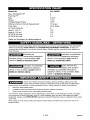
FULL ONE YEAR WARRANTY AIR COMPRESSOR
If this CRAFTSMAN Air Compressor fails due to a defect in material or
workmanship within one year from the date of purchase, Sears will at its
option repair or replace it free of charge. Contact your nearest Sears Service
Center (1-800-4-MY-HOME ®)to arrange for repair, or return the Air
Compressor to the place of purchase for replacement.
If this Air Compressor is used for commercial or rental purposes, this warrant
applies for only ninety days from the date of purchase.
This warranty gives you specific legal rights and you may have other rights
which vary from state to state.
Sears, Roebuck and Co., Dept. 817WA, Hoffman Estates, IL 60179
D30052
2* ENG
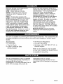
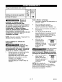
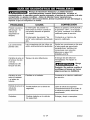
Model No.
919,165361
Max. Developed
Running HP
Bore
Stroke
Voltage-Single
HP
2
1
2.875"
1.25"
Phase
120V
Minimum Branch Circuit Requirement
Fuse Type
Air Tank Capacity
15 amps
Time Delay
6
Approx. Cut-In
Approx. Cut-out
SCFM @ 40 psig
120
150
3.7
SCFM @ 90 psig
2.6
Refer to Glossary
for abbreviations.
[-.'Y.,I
_1_ I_'d[€-lJ]Im]=1IqI_I ::_'_.,I m]::1_11
_1i II[e_]_._
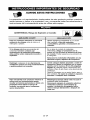
This manual contains information that iS important for you to know and understand. This information
relates to protecting YOUR SAFETY and PREVENTING EQUIPMENT PROBLEMS. To help you
recognize this information_ we use the symbols below. Please read the manual and pay attention to
these sections.
_'_Tlndicates
_'_
a potentially
situation
Indicates an
imminently hazardous
situation which, if not avoided, will
result in death or serious injury.
which, if not avoided, _
result in
minor or moderate injury.
_'f_'_lndicates
_Used
hazardous
hazardous
a potentially
situation
which, if not avoided, could
death or serious injury.
result in
without the
safety alert symbol
indicates a potentially hazardous
situation which, if not avoided, may
result in orooertv damaae.
IhSl_o]-']nq.,1+hd
b"Y.'_l_"_'4 _[IP,[.._l_o]nj[o _]P,[..+
Some dust created by power sanding, sawing, grinding, drilling, and other
construction activities contains chemicals known (to the State of California) to
cause cancer, birth defects or other reproductive harm. Some example of these chemicals are:
lead from leed-based
crystalline
paints
silica from bricks and cement
arsenic and chromium
and other masonry products
from chemically*treated
lumber
Your risk from these exposures varies, depending on how often you do this type of work. To reduce
your exposure to these chemicals: work in a well ventilated area, and work with approved safety
equipment, always wear MSHA/NIOSH
approved, properly fitting face mask or respirator when using
such tools.
When using air tools, basic safety precautions
personat injury.
should
3-ENG
always be followed
to reduce the risk of of
D30052
I I_ I_o] ;111P'.'q
+IInl[,.'9'.,_
_1_ &'i __JL_[,._)III,_]LI_+']IIT[_o
_+]L_,[,._
Save these instructions
Improper operation or maintenance of this product could result in serious injury and
property damage. Read and understand all warnings and operation instructions before
using this equipment,
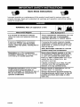
,l;1"l'J "-In
WARNING: Risk of explosion or fire
What Could Happen
How To Prevent It
It is normal for electrical contacts
within the motor and pressure switch to
spark,
Always operate the compressor in a well
ventilated area free of combustible
materials, gasoline, or solvent vapors.
If electrical sparks from compressor
come into contact with flammable
vapors, they may ignite, causing fire or
explosion,
If spraying flammable materials, locate
compressor at least 20 feet away from
spray area. An additional length of hose
may be required,
Store flammable materials in a secure
location away from compressor.
Restricting any of the compressor
ventilation openings will cause serious
overheating and could cause fire,
Never place objects against or on top
of compressor. Operate compressor in
an open area at least 12 inches away
from any wall or obstruction that would
restrict the flow of fresh air to the
ventilation openings.
Operate compressor in a clean, dry wall
ventilated area. Do not operate unit
indoors or in any confined area.
Unattended operation of this product
could result in personal injury or
property damage. To reduce the risk of
fire, do not allow the compressor to
operate unattended.
Always remain in attendance with the
)roduct when it is operating.
Always disconnect electrical power by
moving pressure switch lever to the off
}osition and drain tank daily or after
each use.
D30052
4* ENG
WARNING:
Risk of Bursting
Air Tank: The following conditions could lead to a weakening of the tank, and result
in a violent tank explosion and could cause property damage or serious injury,
What Could Haopen
How To Prevent It
Failure to properly drain condensed
water from tank, causing rust and
thinning of the steel tank.
Modifications
the tank.
or attempted
repairs
Unauthorized
modifications
to the
Drain tank daily or after each use. If
tank develops a leak, replace it
immediately with a new tank or replace
the entire compressor.
to
Never drill into, weld, or make any
modifications to the tank or its
attachments.
unloader valve, safety valve, or any
other components which control tank
pressure.
Excessive vibration can weaken the
air tank and cause rupture or
explosion
ATTACHMENTS
& ACCESSORIES:
Exceeding the pressure rating of air
tools, spray guns, air operated
accessories, tires, and other inflatables
can cause them to explode or fly apart,
and could result in serious injury.
WARNING:
The tank is designed to withstand specific
operating pressures. Never make
adjustments or parts substitutions to
alter the factory set operating
pressures=
For essential control of air pressure, you
must install a pressure regulator and
pressure gauge to the air outlet (if not
equipped) of your compressor. Follow the
equipment manufacturers
recommendation
and never exceed the
maximum allowable pressure rating of
attachments. Never use compressor to
inflate small low pressure objects such
as children's toys, footballs,
basketballs, etc.
Risk from Flying Objects
What Could Happen
The compressed air stream can cause
soft tissue damage to exposed skin
and can propel dirt, chips, loose
particles, and small objects at high
speed, resulting in property damage or
personal injury.
How To Prevent It
Always wear ANSI Z87.1 approved
safety
glasses with side shields when using the
compressor.
Never point any nozzle or sprayer
toward any part of the body or at other
people or animals.
Always turn the compressor off and
bleed pressure from the air hose and tank
before attempting maintenance, attaching
to0_s
5* ENG
Oi" accessories,
D30052
WARNING: Risk of Electrical Shock
What Could Happen
_J
How To Prevent It
Your air compressor is powered by
electricity. Like any other electrically
powered device, If it is not used
properly it may cause electdc shock.
Never operate the compressor outdoors
when it is raining or in wet conditions.
Never operate compressor with
protective covers removed or damaged.
Repairs attempted by unqualified
personnel can result in serious injury
or death by electrocution.
Any electrical wiring or repairs required
on this product should be performed by
authorized service center personnel in
accordance with national and local
electrical codes.
Electrical Grounding: Failure to provide
adequate grounding to this product
could result in serious injury or death
from electrocution.
Make certain that the electrical circuit to
which the compressor is connected
provides proper electrical grounding,
correct voltage and adequate fuse
protection.
See grounding instructions.
,1:1"1'.111=
WARNING:
Risk of Breathing
What Could Happen
How To Prevent It
The compressed air directly from your
compressor is not safe for breathing.
The air stream may contain carbon
monoxide, toxic vapors, or solid
particles from the tank. Breathing these
contaminants can cause serious injury
or death.
Air obtained directly from the compressor
should never be used to supply air for
human consumption. In order to use air
produced by this compressor for
breathing, suitable filters and in-line
safety equipment must be properly
installed. In-line filters and safety
equipment used in conjunction with the
compressor must be capable of treating
air to all applicable local and federal
codes prior to human consumption.
Sprayed materials such as paint, paint
solvents, paint remover, insecticides,
weed killers, may contain harmful
vapors and poisons.
Work in an area with good cross
ventilation. Read and follow the safety
instructions
provided on the label or
safety data sheets for the materials you
ere spraying. Use a NtOSH/MSHA
approved respirator designed for use with
your specific application.
D30052
6 * ENG
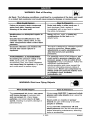
WARNING: Risk of Burns
How To Prevent It
What Could Happen
Never touch any exposed metal parts
on compressor during or immediately
after operation. Compressor will remain
hot for several minutes after operation.
Do not reach around protective shrouds
or attempt maintenance until unit has
been allowed to cool.
Touching exposed metal such as the
compressor head or outlet tubes, can
result in serious burns.
,19",#.,_:
I=
WARNING:
Risk from
Moving
Parts
What Could Happen
How To Prevent It
Moving parts such as the pulley, flywheel,
and belt can cause serious injury if they
come into contact with you or your
clothing.
Never operate the compressor with
guards or covers which are damaged or
removed.
Attempting to operate compressor with
damaged or missing parts or attempting
to repair compressor with protective
shrouds removed can expose you to
moving parts and can result in serious
injury.
Any repairs required on this product
should be performed by authorized
service center personnel.
,19",#.,I:I =
WARNING:
Risk of Falling
What Could Happen
A portable compressor can fall from a
table, workbench, or roof causing
damage to the compressor and could
result in serious injury or death to the
operator,
How To Prevent It
Always operate compressor in a stable
secure position to prevent accidental
movement of the unit. Never operate
compressor on a roof or other elevated
position. Use additional air hose to
reach high locations.
7÷ ENG
D30052
WARNING:
Risk of Serious
Transporting
Injury or Property
Damage
When
Compressor
(Fire, Inhalation, Damage to Vehicle Surfaces)
What Could Happen
How To Prevent It
Oil can leak or spill and could result in
fire or breathing hazard; serious injury or
death can result, oil leaks will damage
carpet, paint or other surfaces in
vehicles or trailers,
WARNING:
Risk
of Unsafe
Always place COMPRESSOR on a
protective mat when transporting to
protect against damage to vehicle from
leaks. Remove COMPRESSOR from
vehicle immediately upon arrival at your
destination.
Operation
What Could Happen
How To Prevent It
Unsafe operation of your air Compressor
could lead to serious injury or death to
you or others.
SAVE THESE
D30052
Review and understand all instructions
and warnings in this manual.
Become familiar with the operation and
controls of the air compressor,
Keep operating area clear of all persons,
pets, and obstacles.
Keep children away from the air
compressor at all times.
Do not operate the product when
fatigued or under the influence of
alcohol or drugs. Stay alert at all times.
Never defeat the safety features of this
product.
Equip area of operation with a fire
extinguisher.
Do not operate machine with missing,
broken, or unauthorized parts.
INSTRUCTIONS
8* ENG
Become familiar with these terms
before operating the unit.
CFM: Cubic feet per minute.
SCFM: Standard cubic feet per
minute; a unit of measure of air
delivery.
PSlG: Pounds per square inch
gauge; a unit of measure of pressure.
Code Certification:
Products that
bear one or more of the following
marks: UL, CUL, ETL, CETL, have
been evaluated by OSHA certified
independent safety laboratories and
meet the applicable Underwriters
Laboratories Standards for Safety.
Cut-In Pressure: While the motor is
off, air tank pressure drops as you
continue to use your accessory.
When the tank pressure drops to a
certain low level the motor will restart
automatically.
The low pressure at
which the motor automatically
restarts is called "cut-in" pressure.
Cut-Out Pressure: When an air
compressor is turned on and begins
to run, air pressure in the air tank
begins to build, it builds to a certain
high pressure before the motor
automatically shuts off, protecting
your air tank from pressure higher
than its capacity. The high pressure
at which the motor shuts off is called
"cut-out" pressure.
Branch Circuit: Circuit carrying
electricity from electrical panel to
outlet.
This unit is capable of powering the following Accessories. The accessories are
available through the current Power and Hand Tool Catalog or full-line Sears
_O_S.
Accessories
• In Line Filter
• Tire Air Chuck
• Quick Connector
(various sizes)
• Air Pressure Regulators
• Oil Fog Lubricators
• Air Hose: 1/4", 3/8" OR 1/2" I.D. in
various lengths
Sets
Refer to the selection chart located
on the unit to select the tools this unit
is capable of powering.
ml_Tujj_[e,_
This air compressor pump is capable
of running continuously. However, to
prolong the life of your air
compressor, it is recommended that a
50%-75% average duty cycle be
q=1
maintained; that is, the air
compressor pump should not run
more than 30-45 minutes in any given
hour.
9- ENG
D30052
IMPORTANT: The outlet being used
must be installed and grounded in
accordance with all local codes and
ordinances.
HOW TO SET UP YOUR
UNIT
Location
of the Air Compressor
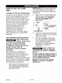
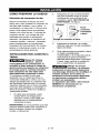
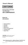
Make sure the outlet being used
has the same configuration as
the grounded plug. DO NOT
USE AN ADAPTER. See
illustration.
Locate the air compressor in a clean,
dry and well ventilated area. The air
compressor should be located at
least 12" away from the wall or other
obstructions that will interfere with
the flow of air. The air compressor
pump and shroud are designed to
allow for proper cooling. The
ventilation openings on the
compressor are necessary to
maintain proper operating
temperature. Do not place rags or
other containers on or near these
openings.
2.
3.
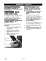
Inspect the plug and cord before
each use. Do not use if there are
signs of damage.
GROUNDING
4.
If these grounding instructions
are not completely understood,
or if in doubt as to whether the
compressor is properly
grounded, have the installation
checked by a qualified
electrician.
INSTRUCTIONS
Risk of Electrical
Shock. In the event
of a short circuit, grounding
reduces the risk of shock by
providing an escape wire for the
electric current. This air
compressor must be properly
grounded.
The portable air compressor is
equipped with a cord having a
grounding wire with an appropriate
grounding plug (see following
illustrations). The plug must be used
with an outlet that has been installed
and grounded in accordance with all
local codes and ordinances.
1.
l1
_lu_
_
_
Grounded
_Outlets
Grou_d_ing Pin
_Risk
of Electrical
Shock. Improper
grounding can result in electrical
shock.
Do not modify the plug provided. If
it does not fit the available outlet, a
correct outlet should be installed
by a qualified electrician.
Repairs to the cord set or plug
MUST be made by a qualified
electrician.
The cord set and plug with this
unit contains a grounding pin.
This plug MUST be used with a
grounded outlet.
D30052
g
10_ ENG
Extension Cords
Voltage
Using extension cords is not
recommended. The use of extension
cords will cause voltage to drop
resulting in power loss to the motor
and overheating.
Refer to the specification chart for the
voltage and minimum branch circuit
requirements.
Protection
Risk of Unsafe
Operation, Certain
air compressors can be operated
on a 15 amp circuit if the following
conditions are met.
Instead of using an extension cord,
increase the working reach of the air
hose by attaching another length of
hose to its end. Attach additional
lengths of hose as needed.
If an extension cord must be used,
be sure it is:
a 3-wire extension cord that has
a 3-blade grounding plug, and a
3-slot receptacle that will accept
the plug on the product
*
and Circuit
1.
Voltage supply to circuit must
comply with the National
Electrical Code.
2.
Circuit is not used to supply any
other electrical needs.
3.
Extension cords comply with
specifications.
4,
Circuit is equipped with a 15
amp circuit breaker or 15 amp
time delay fuse. NOTE: If
compressor is connected to a
circuit protected by fuses, use
only time delay fuses. Time delay
fuses should be marked "D" in
Canada and "T" in the US.
in good condition
no longer than 50 feet
12 gauge (AWG) or larger. (Wire
size increases as gauge number
decreases. 10 AWG and 8 AWG
may also be used. DO NOT
USE 14 OR 16 AWG.)
If any of the above conditions cannot
be met, or if operation of the
compressor repeatedly causes
interruption of the power, it may be
necessary to operate it from a 20
amp circuit. It is not necessary to
change the cord set.
11_ ENG
D30052
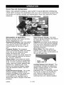
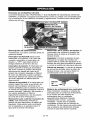
Know
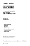
Your Air Compressor
READ THIS OWNER'S MANUAL AND SAFETY RULES BEFORE OPERATING
YOUR UNIT. Compare the illustrations with your unit to familiarize yourself with
the location of various controls and adjustments. Save this manual for future
reference.
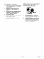
On/Auto/Off Switch
Description
of Operation
Become familiar with these controls
before operating the unit.
On/Auto/Off Switch: Turn this switch
"ON" to provide automatic power to
the pressure switch and "OFF" to
remove power at the end of each
use.
Pressure Switch: The pressure
switch automatically starts the motor
when the air tank pressure drops
below the factory set "cut-in"
pressure. It stops the motor when the
air tank pressure reaches the factory
set "cut-out" pressure.
Safety Valve: If the pressure switch
does not shut off the air compressor
at its "cut-out" pressure setting, the
safety valve will protect against high
pressure by "popping out" at its
factory set pressure (slightly higher
than the pressure switch "cut-out"
setting).
Outlet Pressure Gauge: The outlet
pressure gauge indicates the air
pressure available at the outlet side
of the regulator. This pressure is
controlled by the regulator and is
always less than or equal to the tank
pressure.
D30052
Tank Pressure Gauge: The tank
pressure gauge indicates the reserve
air pressure in the tank.
Regulator: Controls the air pressure
shown on the outlet pressure gauge.
Turn the knob clockwise to increase
pressure and counterclockwise to
decrease pressure.
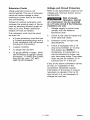
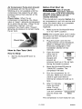
Drain Valve: The drain valve is
located at the base of the air tank
and is used to drain condensation at
the end of each use.
Drain
Valve
Cooling System (not shown): This
compressor contains an advanced
design cooling system. At the heart
of this cooling system is an
engineered fan. It is perfectly normal
for this fan to blow air through the
vent holes in large amounts. You
know that the cooling system is
working when air is being expelled.
12- ENG
Air Compressor Pump (not shown):
Compresses air into the air tank.
Working air is not available until the
compressor has raised the air tank
pressure above that required at the
air outlet.
Check Valve: When the air
compressor is operating, the check
valve is "open", allowing compressed
air to enter the air tank. When the air
compressor reaches "cut-out"
pressure, the check valve "closes",
allowing air pressure to remain inside
the air tank.
Before
First Start Up
_Risk
of Unsafe
Operation. Serious
damage may result if the following
break-in instructions are not
closely followed.
This procedure is required before the
air compressor is put into service and
when the check valve or a complete
compressor pump has been
replaced.
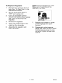
1.
Make sure the On/Auto/Off
is in the "OFF" position.
lever
NOTE: Pull coupler back until it clicks
to prevent air from escaping through
the quick connect.
2.
Plug the power cord into the
correct branch circuit receptacle.
(Refer to Voltage and Circuit
Protection paragraph in the
Installation section of this
manual.)
3.
Open the drain
valve fully to
permit air to
escape and
Open Drain
prevent air
Valve
pressure build up in the air tank
during the break-in period.
4.
Move the On/Auto/Off lever to
"ON/AUTO" position. The
compressor will start.
5.
Run the compressor for 15
minutes. Make sure the drain
valve is open and there is
minimal air pressure build-up in
tank.
6.
After 15 minutes,
close the drain
valve. The air
receiver will fill to
"cut-out" pressure
and the motor will
stop.
How to Use Your Unit
How to Stop:
1.
Set the On/Auto/Off
"OFF".
lever to
The compressor
13_ ENG
Closed Drain
Valve
is now ready for use.
D30052
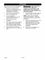
Before
How
Each Start-Up:
1.
Place On/Auto/Off
"OFF".
lever to
2.
Turn the regulator knob counterclockwise to set the outlet
pressure to zero.
3.
Attach hose and accessories.
NOTE: The hose or accessory will
require a quick connect plug if the air
outlet is equipped with a quick
connect socket.
1.
Turn the On/Auto/Off lever to
"AUTO" and allow tank pressure
to build. Motor will stop when
tank pressure reaches "cut-out"
pressure.
2.
Turn regulator knob clockwise to
increase pressure and stop when
desired pressure is reached.
The compressor
Risk of Bursting. Too
much air pressure
causes a hazardous risk of
bursting. Check the manufacturer's
maximum pressure rating for air
tools and accessories. The
regulator outlet pressure must
never exceed the maximum
pressure rating.
D30052
to Start:
14_ ENG
is ready for use.
Customer
Responsibilities
Before
_=ach
LJSe
Check Safety Valve
Daily or
after
each
use
•
Drain Tank
•
Risk of Unsafe
Operation. Unit
cycles automatically when power is
on. When servicing, you may be
exposed to voltage sources,
compressed air, or moving parts.
Before servicing unit unplug or
disconnect electrical supply to the
air compressor, bleed tank of
pressure, and allow the air
compressor to cool.
NOTE: See "Operation"
the location of controls.
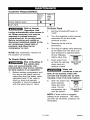
To Check
Safety
To Drain Tank
1.
Set the On/Auto/Off
"OFF".
2.
Turn the regulator knob counterclockwise to set the outlet
pressure to zero.
3.
Remove the air tool or
accessory.
4.
Pull ring on safety valve allowing
air to bleed from the tank until
tank pressure is approximately
20 psi. Release
safety valve ring.
5.
Drain water from
air tank by opening
drain valve on
bottom of tank.
section for
Valve
Risk of Bursting. If
the safety valve
does not work properly, overpressurization may occur, causing
air tank rupture or an explosion.
1. Before star_ing compressor, pull
the ring on the safety valve to
make sure that the safety valve
operates freely. If the valve is
stuck or does not operate
smoothly, it must be replaced
with the same type of valve.
lever to
Open Drain
Valve
_
Water will
condense in the air
tank. If not drained, water will
corrode and weaken the air tank
causing a risk of air tank rupture.
6.
After the water has
been drained,
close the drain
valve. The air
compressor can
now be stored.
Closed Drain
Valve
NOTE: If drain valve is plugged,
release all air pressure. The valve
can then be removed, cleaned, the
reinstalled.
15_ ENG
D30052
ALL MAINTENANCE AND REPAIR
OPERATIONS NOT LISTED MUST
BE PERFORMED BY A TRAINED
SERVICE TECHNICIAN.
NOTE: The hose clamp is not
reusable. You must purchase a new
hose clamp, see the Parts List
Manual or purchase a standard hose
clamp at a local hardware store.
_Risk
5.
Unscrew the check valve (turn
counterclockwise)
using a socket
wrench.
6.
Make sure the valve disc moves
freely inside the check valve and
the spring holds the disc in the
upper, closed position. The
check valve may be cleaned with
a solvent, such as paint and
varnish remover.
7.
Apply sealant to the check valve
threads. Reinstall the check valve
(turn clockwise).
8.
Replace hose and new hose
clamp.
9.
Perform the Break-in Procedure.
See "Break-in Procedure" in the
Operation section.
of Unsafe
Operation. Unit
cycles automatically when power is
on. When servicing, you may be
exposed to voltage sources,
compressed air, or moving parts.
Before servicing unit unplug or
disconnect electrical supply to the
air compressor, bleed tank of
pressure, and allow the air
compressor to cool.
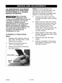
To Replace
or Clean
Check
Valve
1.
Release all air pressure from air
tank. See "To Drain Tank" in the
Maintenance section.
2.
Set the On/Auto/Off lever to
"OFF" and unplug unit.
3.
Remove the hose by removing
the hose clamp.
Hose Clamp
Check
Valve
D30052
16_ ENG
To Replace
NOTE: Arrow indicates flow of air.
Make sure it is pointing in the
direction of air flow.
Regulator
1.
Release all air pressure from air
tank. See "To Drain Tank" in the
Maintenance section.
2.
Set the On/Auto/Off lever to
"OFF" and unplug unit.
3.
Using an adjustable wrench
remove the outlet pressure gauge
and quick connect from the
regulator.
4.
Remove the regulator.
5.
Apply pipe sealant tape to the
nipple on the standpipe.
6.
Assemble the regulator and
orient as shown.
7.
Reapply pipe sealant to outlet
pressure gauge and quick
connect.
8.
Reassemble outlet pressure
gauge and quick connect. Orient
outlet pressure gauge to read
correctly. Tighten connect with
wrench.
17_ ENG
D30052
Before you store the air compressor,
make sure you do the following:
Risk of Bursting.
Water will
condense in the air tank. If not
drained, water will corrode and
weaken the air tank causing a risk
of air tank rupture.
1.
Review the "Maintenance"
section on the preceding pages
and perform scheduled
maintenance as necessary.
2.
Set the On/Auto/Off lever to
"OFF" and unplug unit.
7.
3.
Turn the regulator
counterclockwise
and set the
outlet pressure to zero.
4.
Remove the air tool or
NOTE: If drain valve is plugged,
release all air pressure. The valve
can then be removed, cleaned, then
reinstalled.
8.
accessory.
5.
Pull ring on safety valve allowing
air to bleed from the tank until
tank pressure is approximately
20 psi. Release safety valve ring.
6.
Drain water from air tank by
opening drain valve on bottom of
tank.
D30052
g.
18_ ENG
After the water has been drained
close the drain or drain valve.
Protect the electrical cord and air
hose from damage (such as
being stepped on or run over).
Wind them loosely around the
compressor handle. (If so
equipped)
Store the air compressor
clean and dry location.
in a
d:{ollJ :] il ::F,."]
-"[oIo]l III _[I
_Risk
of Unsafe Operation. Unit cycles automatically when
power is on. When servicing, you may be exposed to
voltage sources, compressed air, or moving parts. Before servicing unit
unplug or disconnect electrical supply to the air compressor, bleed tank of
pressure, and allow the air compressor to cool.
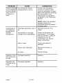
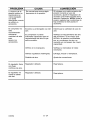
PROBLEM
CAUSE
CORRECTION
Pressure switch does not
shut off motor when
compressor reaches "cutout" pressure.
Move On/Auto/Off lever to
the "OFF" position, if the
outfit does not shut off
contact a Trained Service
Technician.
Pressure switch "cut-out"
too high.
Contact a Trained Service
Technician.
Air leaks at
fittings.
Tube fittings are not tight
enough.
Tighten fittings where air can
be heard escaping. Check
fittings with soapy water
solution. Do Not
Air leaks in air
tank or at air
tank welds.
Defective air tank.
Air leaks
between head
and valve plate.
Leaking seal.
Contact a Trained Service
Technician.
Air leak from
safety valve,
Possible defect in safety
valve,
Operate safety valve
manually by pulling on ring.
If valve still leaks, it should
be replaced.
Knocking
Possible defect in safety
valve,
Operate safety valve
manually by pulling on ring.
If valve still leaks, it should
be replaced.
Excessive tank
pressure - safet
valve pops off.
Overti_hten.
Noise.
Air tank must be replaced.
Do not repair the leak.
Risk of
Bursting.
Do not drill into, weld or
otherwise modify air tank
or it will weaken. The tank
can rupture or explode.
19_ ENG
D30052
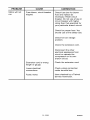
PROBLEM
Pressure reading
on the regulated
pressure gauge
drops when an
accessory is
used.
CAUSE
CORRECTION
It is normal for "some"
)ressure drop to occur.
If there is an excessive
amount of pressure drop
when the accessory is used,
adjust the regulator following
the instructions in the
"Description of Operation"
paragraph in the "Operation
Section.
NOTE: Adjust the regulated
)ressure under flow
conditions (while accessory
is being used).
Prolonged excessive use of
air.
Decrease amount of air
Compressor is not large
enough for air requirement.
Check the accessory air
requirement. If it is higher
than the SCFM or pressure
supplied by your air
compressor, you need a
larger compressor.
Hole in hose.
Check and replace if
required.
Check valve restricted.
Remove and clean, or
replace.
Air leaks.
Tighten fittings.
Regulator knob
has continuous
air leak.
Damaged regulator.
Replace.
Regulator will
not shut off air
outlet.
Damaged regulator.
Replace.
Compressor is
not supplying
enough air to
operate
accessories.
D30052
20_ ENG
usage.
PROBLEM
Motor will not
run.
CAUSE
CORRECTION
Fuse blown, cimuitb_aker
tdpped.
Check fuse box for blown
fuse and replace as
necessary. Reset circuit
breaker. Do not use a fuse or
circuit breaker with higher
rating than that specified for
your particular branch circuit.
Check for proper fuse. You
should use a time delay fuse.
Check for low voltage
)roblem.
Check the extension cord.
Disconnect the other
electrical appliances from
circuit or operate the
compressor on its own
branch circuit.
Extension cord is wrong
length or gauge.
Check the extension cord.
Loose electrical
connections.
Check wiring connection
inside terminal box.
Faulty motor.
Have checked by a Trained
Service Technician.
21_ ENG
D30052
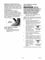
._I-'I_o]_V_l
*_-'!
_o]
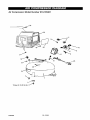
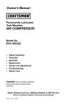
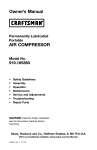
Air Compressor
Model Number 919.165361
33
1
Torqueto 10*20 in-lbs 3_'
D30052
22- ENG
-IIm]¥,___,__
_v
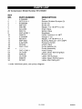
Air Compressor
KEY
NO.
1
2
3
4
5
7
8
9
10
11
12
14
15
18
19
20
21
24
26
28
33
34
Model Number 919.165361
PART NUMBER
Z-D26909
SST-5314-1
91895680
SSF-621
D30198
AC-0430
D20114
CAC-4296-1
D20675
Z-D23004
SS-2071
SSP-6021
Z-D27226
D27022
CAC-1254
+
CAC-1206-1
LA-3109
D26618
LA-3108
D30075
D21921
DESCRIPTION
Tank
Recess Rubber Bumper (3)
Screw (3)
Screw (2)
Nipple, 1/4-18 NPTX 2.50
Drain Valve
Safety Valve
Regulator
Quick Connect 1/4 NPT
Gauge 2" (2)
Nipple, 1/4-18 NPTX 1.5
Bushing Reducer 1/8-1/4NPT
Pressure Switch
Check Valve
Pump Isolator (4)
Pump Assembly
Hose Clamp
Label, Drain Tank Eng/Spa
Power Cord
Label, Hot Surface
Label, Sears Performance
Label, Star Rating #3
+ order individual parts, see pump diagram
23_ ENG
D30052
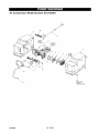
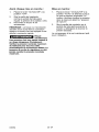
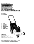
Air Compressor
Model Number 919.165361
2O
\19
D30052
H_d Tigh_
Torque
24_ ENG
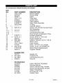
Air Compressor
KEY
NO.
1
2
3
4
5
6
7
8
9
10
11
11-1
11-2
11-3
12
13
14
15
17
18
19
20
21
23
Model Number 919.165361
PART NUMBER
CAC-1320
D25735
D25877
CAC-1212
D22253
Z-D24819
Z-D29777
SSG-8169
+>
x
SSF-3147
>
+ D21127
+
+ .........
Z-D27171
x
SUDL-9-1
D25731
x
SSF-995
D27279
CAC-1206-1
H-7051
x
SSF-3156
Z-D27196
A00470
x
>
+
DESCRIPTION
Shroud (right)
Shroud (left)
Head
Tube Seal
Outlet Tube
Head Gasket
Valve Plate Assembly
O-Ring
Cylinder Sleeve
Screw, 3/8-16 UNC Socket Head
Rod Assembly
Screw # 10-24
Connecting Rod Cap
Pre-Formed Compression Ring
Endbell Assembly
Screw, #8-32 x .375/.344
Pump Isolator (5)
Washer Screws 10-24 x 7/8 (4)
Motor Cord
Hose Clamp
Hose, 1/4" tD x 10" Length
Screw, 10-9 x .50 Plastite (5)
Motor Brush Replacement
Support Handle
Available Kits
D24721
KK-4929
KK-4964
D30324
Isolator Kit
Fastener Kit
Connecting Rod Kit
Ring Kit
Notlllustrated
LA-3270
D30052
D20598
D21109
9-18441
H-7048
AC-0625
Label, Warning Eng/Span
Owners Manual
Quick Connect Plug, Female
Quick Connect Body, Female
Nailer Finish/Brad
Air Hose 3/8" x 25'
Sealant Tape
25_ ENG
D30052
GARANT|A
CUADRO
26
DE ESPECIFICACIONES
DEFINICIONES
DE NORMAS
IMPORTANTES
INSTRUCCIONES
GLOSARIO
DE SEGURIDAD
27
.............................
DE SEGURIDAD
27
......................
28-32
..........................................................
ACCESORIOS
INSTALACION
OPERACION
33
34-38
......................................................
36-38
....................................................
SERVICIOS Y REGULACIONES
39
......................................
40-41
.......................................................
GU(A DE DIAGNOSTICO
NOTES/NOTAS
33
..................................................
.....................................................
MANTENIMIENTO
ALMACENAJE
33
.......................................................
CICLO DE SERVICIO
CONTRATOS
......................................
DE PROBLEMAS
42
.............................
43-45
.......................................................
DE PROTECCION
46
PARA REPARACIONES
LISTA DE PARTES
.................................................
COMO SOLICITAR
PIEZAS PARA REPARACION
.....................
47
22-28
....................
GARANT|A TOTAL DE UN AI_IO DEL COMPRESOR
contratapa
DE AIRE
Si este compresor de aire Craftsman fallase debido a defectos de materiales
o de fabricaci6n dentro del aSo de su fecha de compra, Sears, a su opei6n, Io
reparar& o reemplazar& sin eosto alguno. Comuniquese con el Centro de
Servicio Sears m&s cercano (1-800-4-MY-HOME) para coordinar su
reparaci6n, o devuelva el compresor de aire al lugar donde Io compr6 para
que Io cambien.
Si este compresor de aire se usase con fines comerciales o para alquiler, esta
garantia se aplica s61o durante los primeros noventa dias a partir de su fecha
de compra.
Esta garantia le otorga derechos especfficos y usted podrfa tener otros
derechos que varian de un estado a otto.
Sears, Roebuck and Co., Dept. 817WA, Hoffman Estates, IL 60179
D30052
26- SP
Modelo N °
Max. HP desarrollado
Potencia de trabajo
Di&metro interior
Carrera
Voltaje-corriente manofAsica
Circuito mfnimo requerido
Tipo de fusibleAcci6n
retardada
Capacidad de aire en el tanque
Presi6n de eorte de entrada
Presi6n de corte de salida
919.165361
2
1 HP
2,875 pulg. (73.0 mm)
1,25 pulg. (31,8 mm)
120V
15A
6 Galones (22,7 Iitros)
120 psig
150 psig
3,7 Calibre de Iibras
SCFM a 40 psig
pot pulgada cuadrada
2,6 Calibre de Iibras
pot pulgada cuadrada
SCFM a 90 psig
Refierase al glosario para descifrar
las abreviaturas.
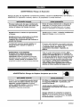
SEGURIDAD
Y PREVENCION
DE PROBLEMAS
DEL EQUIPO: Para ayudar al
reconocimiento
de esta informaci6n,
heroes utilizado los sfmbolos mostrados abajo.
Sirvase leer el manual y prestar atenci6n a dichas secciones.
_
Indicauna sitaaci6nde
inminente riesgo, la
cual, si no es evitada, causara la muerte
o lesionee series.
_
Indica una situaci6n
potencialmente
peligrosa, la cual, si no es evitada, podria
resultar en lesiones menores o
moderades.
_
Usado sin el sfmbolo
de seguridad de
alerta indica ana situaci6n potencialmente
riesgosa la que, si no es evitada, podria
causar da_os en la propiedade.
potencialmente riesgosa, que si no es
evitada, podrfa resultar en la muerte o
lesiones serias,
IIlv_
I _o] :i L't_i t =[--_
_l_,[-._l[((o_
[
ID1_ [._€-!1 ] i1117,.I
i)
_
Algunos tipos de aserr[n creados pot m&quinas electricas de Iijado, aserrado,
3motado, perforado u otras actividades de la construcci6n, contienen
materiales qu_micos conocidos (en el Estado de California) como causantes de c&ncer, defectos de
nacimiento u otros d_os del aparato reproductivo. A_gunos ejemplos de dichos productos quimicos son:
•
El plomo contenido en algunas pinturas con base de plomo
Sflice cristalizado proveniente de los ladrillos, el cemento y otros productos
Ars6nioo y oromo provenientes del tr_tamiento qufmico dado a la madera
de albaSilerfa
Su r_esgo a dichas exposiciones variar& dependiendo de la frecuencia con ta que usted realice
diferentes tipos de trabajo. Para reducir su exposici6n a la acci6n de dichos agentes quimicos:
trabaje en zonas bien ventiladas+ y h&galo con equipo de seguridad aprobado, use siempre protecci6n
facial o respirader MSHA / NIOSH aprobados cuande deba utilizar dichas herramientas.
AI utilizar herramientas neum&tioas tambi_n deben tomarse
de reducir la posibilidad de riesgo de lesiones personales.
27_ SP
precauciones
bAsicas de seguridad,
a fin
D30052
GUARDE
ESTAS INSTRUCCIONES
La operaci6n o el mantenimiento
inadecuados
de este producto
serias lesiones y dafios a la propiedad.
Lea y comprenda todas
instrucciones
de funcionamiento
antes de utilizar este equipo.
podrian ocasionar
las advertencias
e
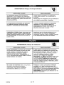
',]=lm[_ ;{_
ADVERTENCIA:
qud
puede
Riesgo de Explosi6n o Incendio
occurrir
cbmo
prevenirlo
Para los contaotos el_ctricos es normal la
existencia de chispas entre el motor y el
intermptor a presi6n.
Opere siempre el compresor en un sector
bien ventilado y libre de materiales
combustibles, gasolina o emanaciones de
solvente=
Si Ias chispas el_=ctricas provenientes d_
compresor tomaran contacto con
emanaciones de materiales inflamables,
ellos podrian arder originando incendio o
explosibn.
En un &tea de rociado de materiales
infiamables, ubique al compresor por Io
menos a 6,1m (20 pies) de distancia del _rea
de rociado. Podrla requerirse una extensi6n de
la manguera,
Almacene
ubicaci6n
los materiales inflamables en una
segura, alejados del compreson
Restringir cualquiera de las aberturas de
ventilacibn causar_ un serio recalentamiento
y podrla producir un incendio.
Jamds coloque objetos apoyados o sobre el
compresor. Opere el compresor en un sector
abierto, por Io menos a 30 cm (12 pulgadas)
alejado de cualquier pared u obstrucci6n
que
restrinja el flujo de aire fresco alas aberturas de
ventilaci6n,
Opere el compresor en un sector limpio, seco, y
bien ventilado, NO opere la unidad en espacios
cerrados o cualquier drea confinada.
Dejar desatenido este producto mientras el
mismo est& en funcionamiento
puede
resultar en lesiones personales o da_os a la
propiedad= Para reducir el riesgo de
incendio, no permita que el oompresor
opere desatendido.
Mant_ngase siempre alerLa cada vez que el
_roducto este funcionando.
D30052
Desconecte siempre el suministro el_ctrico
moviendo la palanca conmutadora de
presi6n a la posici6n de apagado (off), y
drene el tanque diariamente o despu{_s de
cada uso=
28- SP
d=l![_;{q
F 3%q
ADVERTENCIA:
T_ue
de aire:
determinar
las siguientes
su explosibn
qud puede
Riesgo
de Explosibn
condiciones
violenta,
dafios
podrian,
causar
a la propiedad
occurrir
el debilitamiento
o serias
cbmo
del tanque,
prevenirlo
Drenaje inadecuado del agua condensada
en el tanque, siendo la causa del bxido que
reduce el espesor del tanque de acero,
Drene el tanque diariamente o despu_s de
cada uso. Si el tanque genera una p_rdida,
reempl&celo inmediatamente con un nuevo
tanque o reemplace el compresor completo.
Modificaciones
al tanque,
Jambs perfore, suelde, o efectOe modificacibn
alguna al tanque o sue accesorios.
o intento
de reparaciones
y
lesiones.
Modificaciones
no autorizadas
a la vblvula
de descarga, vblvula de seguridad o
cualquier otto componente
que controle la
presibn del tanque.
La vibracibn excesiva puede debilitar el
tanque de aire y causar su ruptura o
explosibn,
El tanque est& disebado para resistir presiones
operativas especfficas. Jambs efectbe ajustes
o sustituya partes que alteren las
regulaciones
de presibn originales de
fbbrica=
AGREGADOS Y ACCESORIOS
El exceso a los valores de presibn
establecidos para las hen amientas
_m_tic_,
pistoIas rociadoras, accesorios
activados por aire, cubiertas y otros obietos
inflables, puede causar su explosibn o set
arrojado& pudiendo ocasionar serias lesiones.
Para un control esencial de la presibn, debe
usted instalar un regulader y un medidor de
presibn a la salida del aire de su compresor. (Si
no estuviese equipado) Siga las recomendaciones
de los fabricantes de SU equipo y jam_s exceda
los vaIores m&ximos de presibn permifidos para
los accesorios, Jam_s use el compresor
para
inflar objetos que requieren poca o baja
presibn, tales como juguetes para los ni_os,
pelotas de f&tbol, pelotas de basquat, etc=
d=l![d;{q
ADVERTENCIA:
Riesgo de Objetos
Arrojados pot el Aire
qud puede occurrir
cbmo prevenido
El chorro de aire comprimido puede causar
daflos sobre los tejidos blandos de la piel
expuesta, y puede propulsar suciedad,
astillas, partlculas sueltas y pequebos objetos a
alia velocidad, ocasionando dafios a la
propiedad o lesiones personales.
AI utilizar el compresor, use siempre anteojos
de seguridad ANSI Z87.1 aprobados, con
proteccibn lateral.
Jamds apunte ninguna boquilla o
pulverizador hacia partes del cuerpo, a otras
personas o
animales.
Apague siempre el compresor y purgue la
presibn de la manguera deI aire y deI tanque,
antes de intantar el mantanimiento, el acople
de herramientas o accesorios.
29* SP
D30052
•,,l
::1nnl
[_1r,{q
ADVERTENCIA:
qud
puede
Riesgo
de choque
eldctrico
occurrir
cbmo
_
prevenirlo
Su compresor de aire est& accionado pot
electricidad. Como cua_quier otto dispositivo
el_ctrico impu[sado e_'tricamente,
si no se Io
utiliza adecuadamente,
podria causarle una
descarga el_ctrica,
Jam_s opere el compresor a la intemperie
cuando est_ Iloviendo o en condiciones de
humedad.
Nunca opere el compresor sin sus defensas o
sus cubiertas removidas o da_adas.
Las reparaciones intentadas pot personal
no calificado podrian ocasionar serias
_esiones o la muerte por electrocuci6n,
Cua[quier conexibn el_ctrica o reparaci6n
requerida por este producto debe ser
efectuada pot personal autorizado
de los
servicentros de acuerdo a los c6digos
el_ctricos naciona[es y locales.
CONEXI(_N A TIERRA: Dejar de proveer una
adecuada conexibn a tierra a este producto
podr_a ccasionar lesiones serias o la muerte
por electrocucibn. Vet instrucciones para la
puesta a tierra.
Asegt_rese que el circuito el_ctrico al cual
est_ conectado el compresor, suministra
apropiada conexibn a tierra, tensi6n correcta
y una adecuada pmteccibn de fusibles.
[-,.]:4unl
It1:To]
ADVERTENCIA:
Riesgo de Inhalacibn
qud puede occutrit
cbmo prevenirlo
E_ aire comprimido proveniente del compresor
no es sano para respirar. El chorro de aire
puede contener mon6xido de carbono,
vapores t6xicos o partlculas sblidas
provenie_es del tanque. La inhalaci6n de
dichos contaminantes
puede Uegar a causar
serias lesiones o la muerte=
E_ aire obtenido directamente del compresor
am_is deber_ ser utilizado para proveer aim
_ara consumo humano. Para poder utilizar el
aire producido por este compresor y hacerlo
respirable, deber&n instalarse un filtro
adecuado y un equipo de segur[dad
intercalado= Los filtros intercalados tanto como
el equipo de seguridad utilizado en conjunto
con el compresor, deber_n ser capaces de
}rocesar el tratamiento del aire de acuerdo a
todos los cbdigos locales y federales, previo
al consumo humano.
El tociado de materiates tales como
so[ventes, removedores de pintura,
insecticidas, mata hierbas, contienen
emanaciones da_inas y venenosas.
Trabaje en un &tea con buena ventilacibn
cruzada. Lea y siga las instrucciones de
seguridad provistas en el r6tulo o en los datos
de $as hojas de seguridad del material que est_
}ulverizando.
Use el respirador aprobado
NIOSWMSHA
designado para utilizarse con su
aplicaci6n especffica.
D30052
pintura,
30- SP
",,1
=ltq[_ t,{_
ADVERTENCIA:
Riesgo de Quemaduras
qu_ puede occurrir
cdmo
prevenitlo
Jam_is toque partes de metal expuestas en el
compresor durante o inmediatamente
despu_s
de la operaci6n, el compresor permanecerd
caliente pot ratios minutos luego de la
operaci6n,
Tocar el metal expuesto tal como el cabezal
del compresor o los tubos de sa_ida del
escape, puede ocasionarie serias
quemaduras.
No Io cubr8 con fundas protectoras o intente el
mantenimiento
basra que la unidad haya
alcanzado su enfriamJento.
",,1
=ltq[_ t,{_
ADVERTENCIA:
que
puede
Riesgo
de Partes
M6viles
occurrir
_)
cdmo
prevenitlo
Partes movibles tales como Ia polea, el
volante y la correa podr{an set la causa de
serias lesiones si elias entr_ran en contacto
con usted o sus ropas.
Nunca opere el compresor sin sus defensas
o sus cubiertas removidas o da_adas.
Intentar
operar el compresor con sus
partes da_adas o faitantes, o la reparacibn
del compresor con sus protecciones
removidas, puede exponerlo a usted a
partes movibles, que podrlan resultar en
lesiones serias=
Cualquier reparaci6n requerida pot este
producto debe ser efectuada por personal
autorizado
de los servicentros.
",,1
=ltq[_ t,{_
ADVERTENCIA:
qu_
puede
Riesgo
de Caida
occurrir
Un compresor port&til puede caerse de la
mesa, el banco de trab_o o del techo da_ando
al compresor y pudiendo resultar en serias
lesiones o la muerte del operador=
_
cdmo
orevenitlo
Opere siempre el compresor en una posici6n
estable y segura a fin de prevenir el
movimiento accidental de la unidad. Jam_s
Opere el compresor sobre un techo u otra
posici6n elevada. Utilice mangueras
adicionales de aire para alcanzar posiciones
altas.
31 _ SP
D30052
ADVERTENCIA:
Riesgo de Serias
Transportar
el Compresor
(Fuego, inhalaci6n,
qud
puede
Lesiones
o Da_os
da_o a la superficie
a la Propiedad
de vehlculos)
occurrir
c6mo
El aceite puede derramarse y e_lo podr{a
resultar en serias lesiones o la muerte debido
al riesgo de incend+o o inhataci6n, El derrame
de aceite daSa alfombras, pinturas u otras
superficies de vehlculos o remolques+
al
prevenido
Deposite el compresor sobre una atfombrilla
protectora cuando Io transporte= a fin de
proteger al vehlculo de p6rdidas por goteo,
Retire el compresor del vehiculo
inmediatamente
despu_s de su arribo 81
destine,
i,l::ll [_ r,{+
ADVERTENCIA:
qud
puede
Riesgo
de Operacibn
Insegura
occurrir
c6mo
La operation insegura de su compresor de
aire podria ocasionarle serias lesiones o la
mueF_e a usted u otros.
prevenido
Revise y comprenda todas las instrueciones
advertencias contenidas en este manual.
y
Familiarlcese con los m_todos de operaci6n
y control del eompresor de aire+
Mantenga libre la zona de operacienes
persona alguna, 8J3ima_es dorr_sticos y
ebst&culos+
de
Mantenga alejados a los ni_os del compresor
de aire en todo memento.
No opere el producto cuando se encuentre
fatigado o bajo la influencia del alcohol o
drogas. Est_ alerta en rode memento.
Jam_s a_ere los elementos
este producto.
de seguridad
Equipe la zona de operaciones
extinguidor de fuego.
con un
No opere la m_quina si _sta tiene partes
faltantes, rotas o no autorizadas.
CONSERVAR
D30052
ESTAS INSTRUCCIONES
32_ SP
de
Familiarlcese con los siguientes terminos,
antes de operar la unidad:
CFM: (Cubic feet per minute) Pies cQbicos
pot minuto.
SCFM: (Stardard cubic feet per minute)
Pies cQbicos est&ndar per minuto; una
unidad de medida que permite medir la
cantidad de entrega de aire.
PSIG: (Pound per square inch) Libras pot
pulgada cuadrada.
ASME: American Society of Mechanical
Engineers (Sociedad Americana de
Ingenieros Mec&nicos); hecho probado
inspeccionado y registrado en
cumplimiento de los est&ndares de la
ASME.
Cbdigo de certificacibn:
Los productos
que usan una o m_s de las siguiantes
marcas: UL, CUL, ETL, CETL, hart sido
evaluados por OSHA, laboratorios
independientes
certificados an seguridad,
y reenen los est&qdares suscriptos pot los
laboretorios dedicados ala certificacion
de la seguridad.
Presibn minima de torte: Cuando el
motor esta apagado, la presion del tanque
de aire baja a medida que usted continQa
usando su accesorio. Cuando la presion
del tanque baja al valor fijado en f&brica
como punto bajo, el motor volvera a
arrancar autom&ticamente.
La presi6n
baja ala cual el motor arranca
automaticamente,
se llama presi6n
"minima de corte".
Presibn mdxime de corte: Cuando un
compresor de aire se enciande y
comienza a funcionar, la presiSn de aire en
el tanque comienza a aumantar. Aumenta
hasta an valor de presion alto fijado en
f&brica antes de que el motor
autom&ticamente
se apague protegiendo
a su tanque de aire de presiones m&s
altas que su capacidad.
La presiSn alta a
la cual el motor seapaga se llama presion
"m_xima de corte".
Ramal: Circuito el_ctrico que transporta
electricidad desde el panel de control
haste el tomacorriente.
Esta unidad es suficisnte para ebastecer de energie electrica a los siguientss accesorios. Estos se
encuentran disponibles a traves del cat&logo pare herremientas electrices y manuales>en
cualquiera de los comercios que mantiene la linea complete de SEARS.
Accesorios
• Filtro de intercslar
• Reguladores de presi6n de aire.
• Lubricadores pare niebla de aceite.
• Boquilla para infler cubiertas.
• Juego de conexi6n rapida (varies
• Manguera deaire:
1/4">3/8" o 1/2" DL en distintas longitudes.
medidas)
Refi_rase al grafico de selecci6n ubicado
sobre la unidad, pare elegir el tipo de
herramienta que esta unidad es eapaz de
hacer funcionar.
[e,][e,lEo]I m]:4 _o,][o]
Esta bomba compresora de aire es capaz
de funcionar continuamente, sin embargo
para prolonger la vide t_til de su
eompresor de aire se reeomienda
mantener un cielo promedio de servicio
que oscile entre el 50% y el 75%; ello
signifiea que la bomba compresora no
deberia trabajar mAs de 30 a 45 minetos
por hora.
33- SP
D30052
C6MO PREPARAR LA UNIDAD
Ubicacibn
del compmsor
2.
de aire
Ubique al compresor de aire en una zona
limpia>seca y bien ventilada. El cempresor de
aire debe estar instalado - per Io menos - a
Toma-
una distancia no menor de 12" (30 cm) de 18
pared u otras obstrucciones que pudiesen
interferir con el flujo del aire. La bemba del
compresor de aire yes carcasa hun sido
disefiadas para permitir su enfriamiento
adecuado. Les abertures de ventilaci6n del
corrientes
conectados
a tierra
Espiga de conexi6n a tierra
compresor resultan - entonces - necesarias
para el mantenimiento de esa adecuada
temperatura de funcionamiento. No coloque
3.
generos o contenedores, encima, ni eil las
proximidades de dichas aberturas.
4+
INSTRUCCIONES PARA CONECTAR A
11ERRA
;2°co
de
eventualidad de un cortocircuito, la
conexibn a tierra reduce el riesgo de
electrocucibn proveyendo un conductor
de escape para la corriente eldctrica.
Este compresor de aire debe estar
adecoadamente
conectado a tierra.
El compresor portatil de aire esta
equipado con un cable qae tiene an
conductor destinado a tierra, con una
espiga apropiada para su conexi6n (ver
las siguientes ilustraciones). El enchufe
debe ser atilizado con un toma corriente
que haya sido instalado y conectado a
tierra de acuerdo a todos los c6digos y
ordenanzas locales.
1
Inspescicne el enchufe y su cord6n
antes de cada eso. No use si ex_stieran
signes de dafios<
Si les instruccionesde conexk_n a tierra
no fueran comp_amente
ccmprendides, o si es estuviera ante la
duda acerca de qae el compresor
estuviees adecuadamente
conectado
a tierra, haga vedficar la instalaci6n
por un electricista competente.
_._l_'_Jl
Riesgo de choque
eldctrico. La conexibn
inadecuada a tierra puede determinar
una descarga el_ctrica. No modiflque el
enchufe provisto. Si el miemo no
penetrara el tomacorriente dieponible,
un electricista competente debera
instalar uno apropiado.
La reparacibn del cable o del enchufe
DEBERA ser efectuada por un
electricista competente.
El cable que acompafia a esta
unidad tiene una espiga para
conexi6n a tierra. Esta DEBE set
utilizada con un tomacorriente
conectado a tierra.
IMPORTANTE: El tomacorriente que set&
utilizado debera haber sido conectado a
tierra conforme a todos los c6digos
locales y ordenanzas.
D30052
AsegQrese de que el tomacorriente
que sera utilizado tenga la misma
configaracion que el enchufe de
conexion a tierr& NO UTILtCE UN
ADAPTADOR. Vet figura,
34- SP
Cables
de extensibn
eldctrica
NO se recomienda la utilizaci6n de cables
de extensi6a electrica. El uso de cables
de extensi6n electrica originar& una cafda
de tensi6n, Io que determinar& una
perdida de potencia del motor asi como
su recalentamiento. En lugar de utilizar an
cable de extensi6n el6ctrica, incremente
el alcaace de la manguera de aire dentro
de la zona de trabajo, aSadi_ndole otto
largo de manguera a su extremo. Conecte
los largos adicionaJes de manguera de
acuerdo a su necesidad+
Si - no obstante
extensi6n
Proteccibn
2.
Qua el circuito no sea tr_ilizado para
alimentar ninguna otra necesidad
electrica.
3.
Que los cables de extensi6n
con las especificaciones.
4.
El circuito cuenta con un disyuntor de
15 amperios o an fusible de acci6n
retardada de 15 amperios+ NOTA: Si
el compresor esta conectado a un
circuito protegido pot fusibles, use
solo fusibles de acci6n retardada.
Los fusibles de acci6n retardada
deben estar marcados con la letra
- debe utilizarse una
electrica de 3
conductores, tenga un enchufe de
conexi6n a tierra de 3 hojas, y qua
exista un recept&culo que acepte el
enchufe del producto+
Este en buenas condiciones.
No mas largo que 15,2 m (50 pies).
Cafibre 12 (AWG) o mayor. (La
medida de los cables se incrementa
a medida que su nOmero ordinal
decrece. 10 y 8 AWG pueden ser
usados tambi_n. NO USE 14 N116
AWG).
y del circuito
_
Riesgo de
Operacibn
Lasegura. Ciertos compresores de aire
pueden ser operados en un circuito de
15 A, siempre que se cumplan las
siguientes condiciones:
1.
Que el voltaje suministrado a tray,s de
los tamales del circuito sea de 15 A.
de cable, asegerese de que:
La extensi6n
del voltaje
Acerca del voltaje y la minima cantidad de
circuitos req_._eridos,refierase al cuadro de
especificaciones+
camplan
"D" en Canada y "T" en EE.UU.
Si cualquiera de las condiciones
enumeradas no padiese ser cumplida, o si
el funcionamiento
del compresor causara
reiteradas interrupciones de la energia con
la qae se Io alimenta, podria ser necesario
operar al mismo desde un circuito de 20
A+ Para ello no sera necesario cambiar su
cable de limentaci6n.
35 - SP
D30052
Conozca
su compresor
de aire
LEA ESTE MANUAL DEL PROPIETARIO Y SUS NORMAS DE SEGURIDAD ANTES DE
OPERAR LA UNIDAD, Compare las ilustraciones contra su unidad a fin de familiarizarse
con la ubieaci6n de los distintos controles y regulaciones Conserve este manual para
referencias futuras.
Descripcibn
de operaciones
Familiarfcese con estos controles
operar la unidad.
antes de
Interruptor
On/Auto/Off=
Mueva este
interruptor a la posici6n "ON" para dar
contacto automatico al interruptor de
presi6n, y "OFF" para interrumpir la
energfa el_ctrica al termino del uso.
Regulado_ Controla la presi6n de aire
indicada en la salida del medidor de
presi6n.Gire la perilla del regulador en el
sentido del reloj para aumentar la presi6n
y contra el sentido del reloj para reducirla.
Intertuptor
de presibn: El interruptor de
presi6n permite el arranque automatico
del motor cuando la presi6n del tanque
disminuye pot debajo del valor de la
presi6n de conexi6n regulada en f&bric&
El motor se detendr& cuando la presi6n
del tanque alcanee los valores de presi6n
de corte, regulado en fAbrica para su
desconexi6n.
Valvula de drenaje: La valvula de drenaje
se encuentra ubicada sobre la base del
tanque de aire y se usa para drenar la
condensaci6n al fin de cada uso
Valvula de seguridad: Si el interruptor de
presi6n dejara de cortar el suministro de
presi6n del compresor conforme a los
valores prefijados para la presi6n de corte,
la v&lvula de seguridad protegera contra la
presi6n elevada, "saltando" de acuerdo a
los valores prefijados en fabrica
(ligeramente supedores a los de presi6n
de corte de la Ilave interruptora.)
Manbmetro para conttolar le presibn de
salida. Este man6metro indieara la
presi6n de aire disponible a la salida del
regulador. Esta presi6n est& controlada
por el regulador y as siempre menor o
igual que la presi6n del tanque
D30052
Manbmetro de la preeibn del tanque: El
man6metro que controla la presi6n del
tanque indiea la reserva de presi6n del
tanque de aire.
Valvula
de
drenaje
Sistema de enfriamiento (no mostrado):
Este compresor contiene un sistema de
avanzada para el control de enfriamiento.
En el nt]eleo de este sistema de
enfriamiento hay un ventilador
especialmente diseSado. Resulta
perfectamente normal - para este
ventilador - soplar aire en grandes
cantidades a traves de los orificios de
ventilaci6n. De tal manera se podr& saber
que el sistema de enfriamiento trabaja
cuando el aire esta siendo expelido.
36- SP
Bomba de compresibn del aire (no
mostrada): Compdme el aire clentro clel
tanque. El aire de trabajo no se encuentra
disponible hasta que el compresor haya
alcanzado a Ilenar el tanque hasta un nivel
de presidn por encima del requerido para
la salida del aire.
Valvula reguladora:
Cuando el
compresor de aire se encuentra
funcionando, la valvula reguladora esta
"abierta", permitiendo ta entrada del aire
comprimido al tanque de aire. Cuando el
nivel de presi6n del tanque alcanza el
punto de "corte", la v&lvula reguladora "se
cierra% reteniendo la presion del aire
dentro del tanque.
Cbmo utilizar su unidad
C6mo detenerla:
Riesgo
de
Operacibn
Inseguta. Si las sigaientes instrucciones no
fuesen seguidas estrictamente, podr_n
ocurrir serios da_os.Este procedimiento es
necesario antes de poner en servicio al
compresor de aire, y cuando la v_lvula
reguladora o la bomba completa del
compresor haya sido reemplazade.
1.
NOTA: Tire del acoplamiento hacia atrAs hasta
percibir el "clic" que impide el escape del aire
de la conexidn r_pida.
2,
Enchufe el cable de alimentacidn en el
recept&calo del ramal del circuito
correcto. (Referirse aI parrafo "Proteccidn
del voltaje y del circuito" en la seccidn
"lnstalaciSn" de este manual).
3,
Abra eompletamente la
valvula de drenaje a fin
de permitir la salida del
Valvula
C6mo utilizar su unidad
Cbmo
1.
Aseg_rese qae la pa_ancaOn/Auto/Off
est_ en _aposicidn "OFF".
detenerla:
aire e impedir el
Abra la v_lvula
aumento de la presi6n
de drenaje
dentro del tanqae de
aire durante el periodo de asentamiento.
Coloque la posici6n de la Ilave
interruptora On/Auto/Off an la
posicion "OFF".
4.
Mueva la palanca On/Auto/Off a la
posicidn "ON/AUTO". El compresor se
pondra en marcha.
5,
Haga funcionar el compresor durante 15
minutos. Asegt_resede que la v_lvula de
drenaje est_ abierta y que la presidn de
aire acumulado en el tanque sea minima.
6,
Luego de 15 minutos,
cierre la valvula de
drenaje. El aire recibido
ira Ilenando hasta el
punto de "coRe" de
presiSn, y el motor se
detendr&
Cierre la v_ilvula
de drenaje
El compresor estara ahora listo para set usado.
37_ SP
D30052
Avant chaque mise en marche :
Mise en marche :
1
Placez le levier "On/Auto/Off"
position "OFF".
1,
2
Gire la perilla del regulador
contre el sentido del reloj pare
regular la presion de la salida a cero<
Raccordez le boyau et les
aooessoires.
3<
& la
2.
REMARQUE .*Le boyau ou I'accessoire
doit _tre rnuni d'une fiche & connexion
rapide si la sortie d'air est {_quipee d'une
douille & connexion rapide.
Gire la
sentido
presi6n
presi6n
perilla del regulador en el
del reloj para aumentar la
y detengase al aleanzar la
deseada.
Le compresseur d'air est maintenant pr_t
pour I'utilisation
_
Risque
d_clatemenL
Une pression d'air trop _lev6e conduit
un risque dangereux d'_elatemenL
V_rifiez la pression nominale maximum
du fabricant pour tous les outUs
pneomatiques et accessoires utUisds. La
pression de sortie do rdgulateur ne doit
jamais excdder la preesion nominale
maximum.
D30052
Placez le levier "On/Auto/Off" & la
position "AUTO" et attendez jusqu'&
ce que la pression augmente< Le
moteur s'arr6tera Iorsque lapression
darts le r{_servoir atteint la "pression
de rupture".
38- SP
lwff:l _bi _ _1hVlll_ _I I[I
Responsabilidades
del cliente
Antes
de
[_aria_e_te
carla 0 luegode
cadauso
Uso
Verifique la vAlvula de seguridad
Drenaje del tanque
•
Riesgo de
Operaci6n
Insegura. La unidad arranca
automaticamente
cuando esta
enchufada. AI hacer el mantenimiento,
el operador puede quedar expuesto a
fuentes de corriente y de aire
comprimido o a piezas movibles.
Antes de intentar hacer reparaciones,
desconectar el compresor del
tomacorriente, drenar la presidn de aire
del tanque y eeperar a que el
compresor se enfrie.
NOTA: Yea en la secci6n
ubicaci6n de los controles
Cbmo
verificar
"Operaci6n"
la v_ilvula
Cbmo
2.
Gire la perilla del regulador
contra el sentido del reloj para
regular la presi6n de la salida a cero.
3.
Remueva la herramienta
el accesorio.
4,
Tire del aro de la v&lvula de
seguridad dejando purgar el aire del
tanque hasta que este reduzea su
presi6n aproximadamente a 20 PSI.
Suelte el aro de la v&lvula de
seguridad.
5,
Drene el agtJa
contenida en el
tanque de aire,
abriendo la v&lvula
de drenaje ubicada
en la base del
tanque.
de
seguridad
_
1.
Antes de porter en marcha el motor,
tire del anillo de la v&lvula de
seguridad para confirmar la
seguridad de que la misma opera
libremente, si la v&lvula quedase
trabada o no trabajara
comodamente, debera ser
reemplazada pot el mismo tipo de
v_lvula.
el tanque
Coloque la palanca On/Auto/Off
posici6n "OFF".
la
Riesgo de
Explosibn. Si la
valvula de seguridad no trabaja
adeeuadamente,
ego podra determinar
la sobrepresi6n del tanque, creando el
riesgo de su ruptura o explosidn.
drenar
1.
en la
neum_ttic8 o
Abra la v_ilvula
de drenaje
s% °Z',tan"
ue
condensacibn de agua. Si no drena, el
agua Io corroera y debilitard causando
un riesgo de ruptura del tanque de aire.
6.
Una vez drenada el
agua, eierre la
valvula de drenaje.
Ahora el eompresor
de aire podra ser
guardado.
Cierre la v&lvula
de drenaje
NOTA: Si la valvula de
drenaje fuera del tipo enchufe, elimine
toda la presion de aire. La v&lvula podr_
entonces ser extrafda, limpiada y
finalmente reinstalada.
39* SP
D30052
TODO TIPO DE MANTENIMIENTO Y
OPERACIONES DE REPARACION NO
MENCIONADOS, DEBEPJ_N SER
EFECTUADOS POR PERSONAL TECNICO
ESPECIALIZADO,
NOTk La abrazaderade la manguerano es
reutilizable.Debera comprarse una nueva
abrazadera,ver Is lists de parles del manual o
compre una abrazaderaestandar en cualquier
comercio de fetreterfa.
Riesgo de
Operacibn
Insegura, La unidad arranca
automaticamente
cuando esta
enchufada, AI hacer el mantenimiento,
el operador puede quedar expuesto a
fuentes de corriente y de aire
comprimido o a piezas movibles.
Antes de intentar hacer reparaciones,
desconectar el compresor del
tomacorriente, drenar la presibn de aire
del tanque y esperar a que el
compresor se enfrie=
5.
Asegt_e que e_disco de lav_Jvulase
mueva librementedentro de la v_Jvula
reguladoray que el resorte sujete aldisco en
posici6n arguiday cerrada. La v_Jvula
_eguladorapuede set limpiada con sc4vente,
tal corno los utilizadospars pinturas y
removedoresde bamiz.
7.
Aplique selladors los tilamentes roscados
de Is v_lvula reguladora.Reinstalela vgvula
reguladora(girandoen senfido horatio).
8.
RepongaIs mangueray coloque la nueva
abrazadar&
9.
Ejecuteel proceso de "asentamiento". Vea
"Proceso de asentamiento"en la seccidn
Para reemplazar o limpiar la vblvula
reguladora
1.
Ubere toda presi6n de sire deltanque. Vea
"Drena_ del tanque" en la secci6n
mantenimiento.
Desenrosquela v_Jvulareguladors (gireen
sentido antihorado)utilizandouna ILave
tubular.
"Operaci6n".
2_
Apagar la unidad colocando el
interruptor en On/Auto/OFF en
"OFF".
3.
ExtraJgala manguersremo_
abrazaderaque la sujeta.
la
de
D30052
40- SP
Para reemplazar
el regulador
1.
Libere toda la presi6n del aire del tanque.
Vea "Drenaje del tanque" en la secci6n
"Mantenimiento'L
2.
Apagar la unidad colocando el
interruptor en On/Auto/OFF en
"OFF".
3.
Utilizando Lina I_averegLilable, extraiga el
manSmetro de presiSn externa y la
conexiSn rapida del regulador.
4.
Extraiga el regulador.
5.
Aplique cinta selladora de caSerias sobre
el niple de_tubo vertical
6.
Ensamble el regulador y ori_ntelo de
acuerdo a Io mostrado.
NOTA: La flecha indica eI sentido de1flujo del
aire. Aseg_rese que est_ apuntando a la
direcciSn en la que fluye el air&
7.
Reaplique sellador de caSerias al
man6metro de presiSn extema y a la
conexi6n rapida,
8.
Rearme el manSmetro de presi6n de
salida y el conector rapido. Oriente el
manSmetro de salida para permitir su
lectura correctamente. Ajuste las
conexiones con la I_ave.
41_ SP
D30052
Antes de guarder su compresor de aire,
asegQrese de haeer Io siguiente:
Riesgo de
Explosibn. El
agua se condensa dentro del tanque de
aire. Si no se drene, ella corroera
debilitando la paredes del tenque de
aire, originando un rieego de ruptura de
eus paredee.
Revise la secci6n "Mantenimiento"
de las p&ginas precedentes y ejecute
el mantenimiento programado de
aeuerdo a la necesidad.
2
Apagar la unidad colocando el
interruptor en On/Auto/OFF en
"OFF".<
3
Gire el regulador en sentido
antihorario y fije la presi6n de salida
en cero.
NOTA: Si la v&lvula de drenaje estuviese
enchufeda, libere toda la presi6n de aire.
La valvula podr& ser extraida, {impiada y
luego reinstalada.
4
Extraiga la herramienta
el accesorio.
8=
Proteja el cable electrico y las
mangueras de aire de daSos (tales
como ser pisoteados o pasados pot
encima). Enrollelos en forma floja,
alrededor de la manija del compresor.
(Si asf estuviese equipado).
9
Almacene el compresor
sitio limpio y seco.
5=
neumatica
7
o
Tire del anillo de la v&lvula de
seguridad permitiendo el purgado del
aire del tanque hasta que {a presion
del mismo {legue aproximadamente
a
20 PSI. Suelte el aniUo de la vAIvula
de seguridad.
6
Drene el agua del tanque de aire
abriendo la valvula de drenaje
ubicada en el rondo del tanque.
D30052
42_ SP
Una vez que el agua haya sido
drenada, cierre la valvula de drenaje.
de aire en un
[_l_.,_ Im]_ I m]p';l_]Z[T_"-]lli[o,,[o]
I m]"_I _ :To]:] nil=1i_Y;%,."]
Riesgo de Operacibn Insegura. La unidad arranca
automdticamente
cuando esta enehufada. AI hacer el
mantenimiento, el operador puede quedar expuesto a fuentes de corriente y de aire
compdmido o a piezas movibles. Antes de intentar hacer reparaciones,
desconectar el compresor del tomacorriente, drenar la presibn de aire del tanque y
esperar a que el compresor se enfrie.
PROBLEMA
Presi6n excesiva
CAUSA
CORRECCION
El interruptor de presion no
interrumpe ai motor cuando el
compresor aicanza la presion
"de corte _,
Mueva la palanca On/Auto/Off a
la posici6n "OFF% si el equipo
no corta, contacte a un t_cnico
calificado para el servicio.
El interruptor de presion "de
corte" esta calibrado demasiado
alto.
Contacte a un t_cnico de
;ervicio calificado.
Las conexiones
Las conexiones
pierden aire.
estAn suficientemente
Ajuste las conexiones en [as que
el aire puede ser escuchado
escap&ndose. Verifique {as
conexiones con soluoidn
del tanque - la
valvula de
seguridad
dispara.
se
de los tubos no
ajustadas.
jabonosa y agua. NO
SOBREAJUSTE.
Perdida de aire en
el tanque de aire
o en las
soldaduras del
Tanque de aire defectuoso.
El tanque de aire debe ser
reemplazado No repare la
)erdida.
Riesgo
de
tanque de aire.
Explosibn. No perfore, suelde ni
modifique el tanque en forma
alguna porque se debilitara.
Perdida de aire
entre el cabezal
y el plato de
v_lvula.
Perdida en el seliado.
Contacte a un t_cnico caiificado
en servicio
P_rdide de aire en la
v&lvula de
seguridad,
Posible defecto en la valvula de
seguridad,
Opere la valvula de seguridad
manualmente tirando de su anillo. Si
la v&lvula aun pierde, debera set
reemplazada.
Golpeteo.
Posible defecto
de seguridad.
Extraiga y limpie o reemplace.
en la valvula
43- SP
D30052
PROBLEMA
La lectura de la
presi6n sobre un
man6metro (si
viene equipado
con este)
desoiende cuando
se utiliza un
accesorio.
El compresor no
esta
suministrando
suficiente
cantidad de mire
para
operar los
accesorios.
CORRECCI6N
CAUSA
Es normal que ocurra algt_n
descenso en la presi6n.
Excesivo y prolongado
mire.
uso del
Si hubiese una caida excesiva de
presion durante el uso del
aooesorio, ajuste el regulador de
aouerdo alas instrucciones de la
secci6n Operaci6n. NOTA: Ajuste la
presidn regulada bajo condiciones de
flujo (rnientras se est_ usando el
accesorio),
Disminuya la cantidad de uso de
mire.
El compresor no tiene
suficiente capacidad para el
requerimiento de mire al que
esta sometido.
Vedfique el requerimiento de mire
del accesorio. Si es mayor que
SCFM o la presi6n suministrada
pot su compresor de mire, se
neoesita un oompresor de mayor
capacidad.
Orificio en la manguera.
Verifique y reemplace
neoesario.
Valvula reguladora
Extraiga, limpie o reemplace.
restringida.
P_rdida de mire.
Ajuste las conexiones.
El regulador tiene
una fuga
continua de aire.
Regulador dafiado.
Reemplace.
El regulador no
cierra la salida
del mire.
Regulador dafiado.
Reemplace.
D30052
44- SP
si fuese
PROBLEMA
El motor no
funciona.
CORRECCI6N
CAUSA
Fusiblefundido;interruptor
automaticodel circuitodisparado,
Vedfiquela caja de fusibtse observando
la existencia de fusibles fundidos y
sustitQyalosen case de necesidad.
Restablezca el interruptor automatico.
No use un fusible o interruptorautom_ico
con valoresque excedan los
sepecificados papala rarnade su
circuito,
Verifique el uso del fusible adecuado,
Debe usarse un fusible de acci6n
retardada.
Verifique la existencia de problemas
con el bajo voltaje.
Verifique la extensi6n del conductor
el6ctdco.
Desconecte los otros artefactos
el6ctdcos del circuito u opere el
compresor en su ramal de circuito
correspondiente.
El cable de extensi6n electrica
tiene una Iongitud o calibre
err6neo.
Verifique la extensi6n del conductor
el_ctrico.
Conexiones el6ctdcas sueltas,
Verifique la conexi6n en la caja
terminal,
Falla el motor.
Haga verificar por un tecnico de
servicio calificado,
45- SP
D30052
D30052
46-SP
Repair Protection
Agreements
Congratulations on making a smart
purchase. Your new Craftsman '_ product is
designed and manufactured for years of
dependable operation. But like all
products, it may require repair from time
to time. That's when having a Repair
Protection Agreement can save you
money and aggravation.
Purchase a Repair Protection Agreement
now and protect yourself from unexpected
hassle and expense.
Here's what's included
Contratos de Preteccibn pars
Reparaciones
Felicitaciones per hater una compra
inteligente, Su nueva unidad Craftsman ® est&
diseffada y fabricada para afros de operaci6n
confiable; pero come todos los productos de
ca_idad podrian requirir reparaciones de vez
en cuando. Ahi es cuando e_Contrato de
Protecc}6n para Reparac}ones le puede
ahorrar dinero y motestias.
Cornpre ahora un Contrato de Protecci6n
para Reparaciones y prot_jase contra apuros
y gastos inesperados,
Et contrato incluye _osiguiente:
in the Agreement:
[_ Expert service by our 12,000
professional repair specialists
Servicio Experto per uno de nuestros
12.000 profesionales especializados en
reparaoiones.
[_ Unlimited service and no charge for
parts and labor on all covered repairs
Servicio ilimitado sin cargos per
repuestos ni mane de obra per todas las
reparaciones cubiertas,
[_ Product replacement
if your covered
product can't be fixed
[_ Discount of 10% from regular price of
service and service-related parts not
covered by the agreement; also, 10%
off regular price of preventive
maintenance check
Reemplazo de la unidad si su unidad
cubierta no puede repararse.
I_ Descuento de110% en servicios y
repuestos no eubiertos per este contrato.
Tambi6n 10% de descuento del precio
regular per cualquier inspecci6n de
mantenimiento preventive.
[_ Fast help by phone - phone support
from a Sears technician on products
requiring in-home repair, plus
convenient repair scheduling
I_ Asistencia telefbnica rbpida per personal
t6cnico de soporte de Sears para tas
unidades que requieran repararse en su
domocilio en horarios convenientes
para usted.
Once you purchase the Agreement, a
simple phone call is all that it takes for
you to schedule service. You can call
anytime day or night, or schedule a
service appointment online.
Sears has over 12,000 professional repair
specialists, who have access to over 4.5
million quality parts and acceesodee.
That's the kind of professionalism you can
count on to help prolong the life of your
new purchase for years to come.
Purchase your Repair Protection
Agreement today!
Some limitations
and exclusions apply.
For prices and additional information
call 1-800-827-6655.
Sears Installation
Service
For Sears professional installation of home
appliances, garage door openers, water
heaters, and other major home items, in
the U.S.A. call f-800-4*MY-HOME
_
Una vez que usted compre su Contrato, s61o
necesita hacer una simple Ilamada telef6nica
para programar su servicio. Puede Ilamar a
cua_quier hera, en et dia o la noche, o
hacerlo per linea via intemet.
Sears tiene mas de 12.000 profesionales
especializados en reparaciones que tienen
acceso amas 4,5 millones de repuestos y
accesorios de calidad. Ese es et tipo de
profesionalismo con el cual usted puede
contar para ayudarte a prologar la vida etil
de su unidad durante todos los afros per
venir, iCompre hey su Contrato de
Protecci6n para Reparaciones]
Se aplican algunas limitaciones y
exclusiones. Para precios e irrformacibn
adicional, Ilarne al 1-800-827-665&
Servicio de Instalaciones de Sears
,Datainstalaciones profesionales per Sears de
artefactos para el hogar, come abridores de
puertas de garajes calentadores de agua y
otros artefactos grandes del hogar, en
EE.UU. Ilame al t-S00-4-MY-HOME _
47_ SP
D30052
Your Home
For repair - in your home - of all major brand appliances,
lawn and garden equipment, or heating and cooling systems,
no matter who made it, no matter who sold it!
For the replacement parts, accessories and
owner's manuals that you need to do-it-yourself.
For Sears professional installation of home appliances
and items like garage door openers and water heaters.
1-800-4-MY-HOME ®
(1-800-469-4663)
Anytime, day or night
(U.S.A. and Canada)
www.sears.com
www.sears.ca
OurHome
For repair of carry-in productslike vacuums, lawn equipment,
and electronics, call or go on-line for the nearest
Sears Parts and Repair Center.
1-600-486-1222 Anytime,dayor night(U.S.A.on_y)
www.sears.com
To purchase a protection agreement (U.S.A.)
or maintenance agreement (Canada) on a productserviced by Sears:
1-800-827-6655 (U.S.A.)
Para pedir servicio de reparaciSn
a demicUio, y para ordenar piezas:
1.888_SM.HOGAR sM
1-800-361-6665 (Canada)
Au Canada pour service en fran_,ais:
1.800.LE.FOYERMC
(1-8(30-533-6937)
SE/AR$
© Sea_ Roeb_kandCO.
® Regi©ered Trademark / TMTrademark / SMService Mark of Sears, Roebuck and Co.
® Marca RegiMrada / TMMarca de FAbr_ca / sMMarca de Se rvicio de Sears, Roebuck and Co.
McMarque de commerce / M_ Marque d_pos_e de Se_rs, Roebuck _nd Co.