1
For Discount Tecumseh Engine Parts Call 606-678-9623 or 606-561-4983
TECUMSEH
Service Dealer’s and Technician’s Training and Informational Series
Tecumseh
Quick Reference
Service Information
Covers Engine and Transmission Product
ENGINES
www.mymowerparts.com
&
TRANSMISSIONS
For Discount Tecumseh Engine Parts Call 606-678-9623 or 606-561-4983
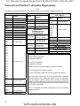
IMPORTANT NOTICE!
Notice Regarding Emissions
This booklet is intended for individuals who have a general
understanding of internal combustion engines, adequate
training, experience and who practice proper tool usage.
Service procedures should be clearly understood and
practiced when servicing Tecumseh Engines.
NOTE
Engines which are certified to comply with California
and U.S. EPA emission regulations for SORE (Small
Off Road Equipment), are certified to operate on
regular unleaded gasoline, and may include the
following emission control systems: (EM) Engine
Modification and (TWC) Three-way Catalyst (if so
equipped).
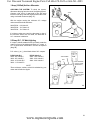
Safety Definitions
Statements in this booklet preceded by the following words
and graphics are of special significance:
WARNING
Or
WARNING
WARNING indicates a potentially hazardous situation which
if not avoided, could result in death or serious injury.
CAUTION
Tecumseh Contact Information
Contact your nearest Authorized Tecumseh Servicing
Dealer if:
• You are unable to perform service procedures
covered in this booklet.
• You have questions about service procedures
covered in this booklet.
• You would like to order service tools.
• You would like to request additional printed
copies of this booklet.
You may find your Authorized Tecumseh Servicing
Dealer on our website at www.TecumsehPower.com
or call Tecumseh Power Company at 1-800-558-5402
or 262-377-2700 if you are located outside the U.S. or
Canada.
CAUTION indicates a potentially hazardous situation which,
if not avoided, may result in minor or moderate injury.
CAUTION
CAUTION without the safety alter symbol indicates a
potentially hazardous situation which, if not avoided, may
result in serious property damage.
NOTE
Refers to important information and is placed in italic type.
It is recommended that you take special notice of all items
discussed on pages 1 and 2 and wear the appropriate safety
equipment.
www.mymowerparts.com
For Discount Tecumseh Engine Parts Call 606-678-9623 or 606-561-4983
Introduction
This booklet contains the quick reference and basic
troubleshooting information previously found on Tecumseh wall
charts and in the Technician's Handbooks.
This booklet is designed to be used as a work bench quick
reference guide when servicing Tecumseh engines and motion
drive systems.
Technician's Note:
Tecumseh engines are manufactured to meet EPA and CARB
standards. As a technician, it is unlawful to re-calibrate or
replace a fuel nozzle or jet (bowl nut) with a part from any other
carburetor that was not originally designed for that engine. All
speed adjustments must remain within the limits that are specified
for each engine and are not to exceed the maximum. This can
only be deviated from if specifically approved by Tecumseh
Power Company, EPA and CARB.
www.mymowerparts.com
i
For Discount Tecumseh Engine Parts Call 606-678-9623 or 606-561-4983
Contents
General Safety Precautions .............................................................................................................................. 1-2
Locating and Reading Engine Model and Specification .................................................................................... 3-5
Quick Reference for Spec. Numbers-To-Model Designation ............................................................................. 6-7
TORQUE SPECIFICATIONS
2-Cycle ............................................................................................................................................................8
4-Cycle ...................................................................................................................................................... 9-10
TROUBLESHOOTING
2-Cycle
Fuel System............................................................................................................................................11
Ignition System .......................................................................................................................................12
4-Cycle
Fuel System............................................................................................................................................13
Ignition System .......................................................................................................................................14
CARBURETORS AND GOVERNORS
2-Cycle
Diaphragm-Dual Adjustment...................................................................................................................15
Diaphragm-Single Adjustment. ...............................................................................................................15
TC/TM Governor Adjustment ..................................................................................................................16
Walbro (WTA, WT) and Tillotson (HU) Diaphragm Adjustment ..............................................................17
Carburetor Pre-Set and Adjustment .......................................................................................................17
Final Idle Mixture Adjustment .................................................................................................................17
Emissionized Tillotson ............................................................................................................................17
Emissionized TC/Tillotson Carburetor ....................................................................................................18
Emissions Carburetor Idle Mixture Adjustment Procedures ...................................................................18
TC/TM Emissionized Tecumseh Carburetor ...........................................................................................18
2-Cycle Engine Speed and Governor Adjustments: TVS/TVXL840 .......................................................19
HSK/HXL840-870/TH139 .......................................................................................................................19
Governors and Linkage for Air Vane................................................................................................. 19-20
4-Cycle
Static Governor Adjustment ....................................................................................................................21
Governor Shaft Pressed in Depth...........................................................................................................22
Small Frame, Vertical and Horizontal .....................................................................................................23
VLV40, 50, 55, 60, 65, 66 .......................................................................................................................23
Retainerless Governor System for Small Frames ..................................................................................23
Medium Frame Vertical...........................................................................................................................23
OV195 ....................................................................................................................................................23
Medium Frame Horizontal ......................................................................................................................24
OVM120, OVXL120, 125 - OHV11-17 - OV358 - OV490 .......................................................................24
OHM120 - OHSK80-130 - OH318 - OH358 ...........................................................................................24
OH120,140,160,180 ...............................................................................................................................24
OH195 / OHH .........................................................................................................................................25
TVT / VTX / OV691.................................................................................................................................25
Engine Speed and Mixture Adjustments ................................................................................................26
Mixture Adjustment Procedure for Adjustable Carburetors.....................................................................27
Common Engine Speed Controls and Governor Linkages............................................................... 28-29
Copyright © 2005 by Tecumseh Power Company
All rights reserved. No part of this book may be reproduced or transmitted, in any form or by any means,
electronic or mechanical, including photocopying, recording or by any information storage and retrieval
system, without permission in writing from Tecumseh Power Company Training Department Manager.
ii
www.mymowerparts.com
For Discount Tecumseh Engine Parts Call 606-678-9623 or 606-561-4983
VLV Governor and Linkage ....................................................................................................................30
Engine Speed and Mixture Adjustments.................................................................................................31
Engine Speed Controls and Governor Linkages .............................................................................. 32-34
Engine Speed Adjustments - 8-18 HP, Cast Iron ....................................................................................35
TVT / VTX / OV691 Governors and Linkage .................................................................................... 36-37
Governor Service.............................................................................................................................. 38-40
ELECTRICAL SYSTEMS
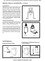
Switches, Sensors, and Solenoids ................................................................................................... 41-42
Low Oil Shutdown Switches ...................................................................................................................41
Low Oil Shutdown Indicator Light ...........................................................................................................41
Low Oil Pressure Sensor ........................................................................................................................41
Low Oil Sensor .......................................................................................................................................42
Fuel Shutdown Solenoids .......................................................................................................................42
On/Off Switches......................................................................................................................................42
Lighted Engine On/Off Rocker Switch w/Low Oil Shutdown ..................................................................42
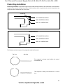
Wiring .....................................................................................................................................................43
Color Codes............................................................................................................................................43
Ammeters ...............................................................................................................................................43
Diodes ....................................................................................................................................................44
Solenoids ................................................................................................................................................44
Key Switches ..........................................................................................................................................45
Importance of Using Correct Switch .......................................................................................................45
Continuity Check for Switches ................................................................................................................46
Charging System .............................................................................................................................. 47-50
Testing Procedures .................................................................................................................................51
D.C. Charging Adaptor ...........................................................................................................................51
350 Milliamp Charging System thru 20 Amp Alternator System ....................................................... 52-62
Standard Wiring Harness Connector Adpaters.......................................................................................63
TECUMSEH and PEERLESS
Model and Specification Numbers .................................................................................................... 64-65
Transaxle Troubleshooting .....................................................................................................................66
Hard Shifting Transaxles and Drive Belts ...............................................................................................67
LTH-2000 Hydrostatic Transaxle Troubleshooting............................................................................ 68-69
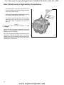
Check Fluid Level on Hydrostatic Transmission .....................................................................................70
1800 / VST Troubleshooting ............................................................................................................. 71-73
Tecumseh / Peerless Lubrication Requirements ....................................................................................74
Peerless Torque Chart ............................................................................................................................75
MISCELLANEOUS SPECIFICATIONS - QUICK REFERENCE AND
IDENTIFICATION CHARTS
Lubrication Requirements ................................................................................................................ 76-77
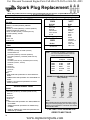
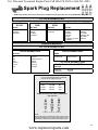
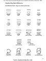
Spark Plug Replacement .................................................................................................................. 78-79
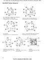
Head Bolt Torque Sequence...................................................................................................................80
Valve Clearance .....................................................................................................................................81
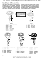
Recoil Quick Reference Parts ................................................................................................................82
Flywheel Key Quick Reference Identification Chart ...............................................................................83
Primer Bulb Identification........................................................................................................................84
Piston Ring Installation ...........................................................................................................................85
Quick Reference for Dipsticks ................................................................................................................86
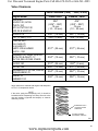
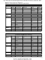
Metric Conversions Factors (approximate).............................................................................................87
www.mymowerparts.com
iii
For Discount Tecumseh Engine Parts Call 606-678-9623 or 606-561-4983
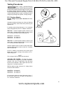
General Safety Precautions
WARNING
Read the original equipment manufacturer’s
manual(s) and this booklet thoroughly before
servicing Tecumseh engines.
Always follow recommended service procedures.
Such procedures affect the safe operation of the
equipment and the safety of you and/or the operator.
Failure to follow the instructions and warnings may
result in serious injury or death. Call Tecumseh
Power Company at 1-800-558-5402 or visit www.
TecumsehPower.com if you have any questions.
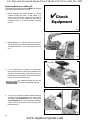
A. Use Personal Protective Equipment
To avoid injury, wear protective
equipment including appropriate
clothing, eyewear, safety shoes and
ear plugs when servicing Tecumseh
products.
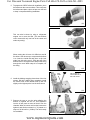
B. Stay Away from Rotating Parts
Rotating parts can cause severe injury
or death. Use special care when making
service adjustments with covers or guards
removed.
Keep tools, hands, feet, hair, jewelry,
and clothing away from all moving parts.
Replace covers and guards before
operating equipment.
C. Stay Away from Hot Surfaces
Parts of equipment being serviced
become extremely hot during operation
and remain hot after the equipment has
stopped. To avoid severe burns, stay
away from hot surfaces or allow the unit
to cool prior to service.
D. Avoid Accidental Equipment
Movement
To prevent accidental movement of equipment, always
set the parking brake. For gear-driven products that do
not have a parking brake, leave equipment in gear and
chock the wheels. Refer to original equipment operator
manuals for additional information.
Pulley bosses that hold the rewind spring inside the
keeper and spring housing may not be secured and can
be easily loosened. Use special care when handling
this housing. Failure to do so could cause spring to “fly
out” which could result in minor or moderate injury.
Always discard gaskets, O-rings and seals after
removal. Use only new gaskets, O-rings and seals for
assembly. Failure to do so could result in leakage from
engine areas that use these parts.
E. Always Provide Adequate Ventilation
To avoid serious injury or death,
always ensure that you are working
in a properly ventilated facility.
Special precautions are required to
avoid carbon monoxide poisoning.
All engine exhaust contains carbon
monoxide, a deadly gas. Breathing
carbon monoxide can cause headaches, dizziness,
drowsiness, nausea, confusion and eventually death.
Carbon monoxide is a colorless, odorless, tasteless gas
which may be present even if you do not see or smell
any engine exhaust.
Deadly levels of carbon monoxide can collect rapidly
and you can quickly be overcome and unable to save
yourself. Also, deadly levels of carbon monoxide can
linger for hours or days in enclosed or poorly-ventilated
areas.
If you experience any symptoms of carbon monoxide
poisoning, leave the area immediately, get fresh air, and
SEEK MEDICAL TREATMENT.
To prevent serious injury or death from carbon
monoxide:
• ALWAYS direct engine exhaust outdoors.
• NEVER run engine outdoors where engine
exhaust can be drawn into a building through
openings such as windows and doors.
F. Use Proper Methods When Cleaning
To reduce the risk of serious injury or death
from fires and/or explosions, NEVER use
flammable solvents (e.g., gasoline) to clean
serviceable parts. Use a water-based,
non-flammable solvent such as Tecumseh
Degreaser Cleaner.
G. Compressed Air Precautions
Never use compressed air to clean debris from yourself
or your clothing. When using compressed air to clean or
dry serviceable parts:
• Wear appropriate eye protection.
• Use only approved air blow nozzles.
• Air pressure must not exceed 30psi (206kPa).
• Shield yourself and bystanders from flying
debris.
H. Inspect and Adjust Brake(s)
Always inspect and adjust flywheel brake components
whenever servicing equipment that has a Tecumseh
engine. Refer to this Technician’s Handbook and
bulletins for proper brake adjustment.
www.mymowerparts.com
1
For Discount Tecumseh Engine Parts Call 606-678-9623 or 606-561-4983
I. Operate Equipment Safely
Operation of equipment presented for service can be
hazardous. To avoid serious injury or death, DO NOT
operate equipment, until:
• all relevant inspection procedures presented in
this book are performed and
• technician is satisfied equipment can be operated
safely.
• Starter pulley springs hold the starter rope and
control tension by winding the rope around the
pulley. Use caution when pulling and releasing
the rope to and from the starter housing. Failure
to do so could cause the rope to unexpectedly
jerk back which could result in minor or moderate
injury.
J. Avoid Gasoline Fires
Gasoline (fuel) vapors are highly flammable
and can explode. Fuel vapors can spread
and be ignited by a spark or flame many
feet away from engine. To prevent injury
or death from fuel fires, follow these
instructions:
• NEVER store engine with fuel in fuel tank inside
a building with potential sources of ignition such
as hot water and space heaters, clothes dryers,
electric motors, etc.
• NEVER remove fuel fill cap or add fuel when
engine is running.
• NEVER start or operate the engine with the fuel
fill cap removed.
• Allow engine to cool before refueling.
• NEVER fill fuel tank indoors. Fill fuel tank outdoors
in a well-ventilated area.
• DO NOT smoke while refueling tank.
• DO NOT pour fuel from engine or siphon fuel by
mouth.
K. Avoid Accidental Starts
To prevent accidental starting when working on
equipment always:
• Disconnect spark plug wire and keep it away
from spark plug.
• Keep the disconnected spark plug wire securely
away from metal parts where arcing could occur.
• Attach the spark plug wire to the grounding post,
if provided.
• Turn off all engine switches.
2
www.mymowerparts.com
For Discount Tecumseh Engine Parts Call 606-678-9623 or 606-561-4983
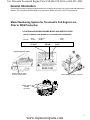
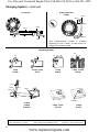
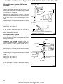
General Information
The following information is being provided to assist you in locating and recording your engine model and specification
numbers. This information will be needed to use this book or obtain parts from a local Tecumseh dealer.
Model Numbering System for Tecumseh’s Full Engine Line
Prior to 2004 Production
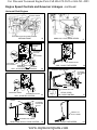
LOCATING AND READING ENGINE MODEL AND SPECIFICATION
THE FOLLOWING WILL BE NEEDED TO LOCATE PARTS FOR YOUR ENGINE.
ENGINE:
Model
TVM195
Specification
150288G
ENGINE MODEL
TVM195
SPEC NO.
150288G
(DOM)
8150C
D.O.M
8150C
Typical Engine I.D. Label
TECUMSEH POWER COMPANY
THIS ENGINE MEETS 1995-1998 CALIF/US
EPA PH1 APPLICABLE EMISSION REGULATIONS FOR ULGE ENGINES FUEL REGULAR
UNLEADED OIL SAE 30
TVM195 150288G (E)
STP318U1G2EA
318
8150 C
ENGINE MODEL NUMBER
LOCATED UNDER COVER
ENGINE MODEL NUMBER LOCATIONS
ENGINE MODEL
NUMBER
LOCATIONS
www.mymowerparts.com
3
For Discount Tecumseh Engine Parts Call 606-678-9623 or 606-561-4983
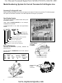
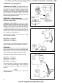
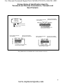
Model Numbering System for Current Tecumseh’s Full Engine Line
Reviewing The Engine ID Label
Effective with the 2004 Model Year, we have changes to the engine I.D. label on our products. The following pages
will explain the information contained on the label dependent on the age of your product.
Specification Number
The numbers following the model number make up the
specification number.
Using model LV195EA-361541B, as an example,
interpretation is as follows:
LV195EA-361541B is the model and specification
number.
(B)
{
{
{
L V 195 E A - 361541B
Warranty Code
Is the specification number used
for properly identifying the parts of
the engine
Indicates a standard power configuration
Indicates EPA/CARB compliant
Indicates a 195 cc displacement
Indicates a vertical shaft configuration
Indicates an L-Head, side valve configuration
Date of Manufacture
The Date of Manufacture (D.O.M.) indicates the
production date.
Typical Engine
I.D. Label
Locations
For this example, 03188BC0010 is the D.O.M. (Date of
Manufacture).
Year
2005
05
Day of
Year
188th
188
Mfg
Facility
B
Assembly
Line / Shift
C
Individual
Serial #
10th unit built
ENGINE MODEL NUMBER
LOCATED UNDER COVER
0010
ENGINE MODEL
NUMBER
LOCATIONS
ENGINE MODEL NUMBER LOCATIONS
4
www.mymowerparts.com
For Discount Tecumseh Engine Parts Call 606-678-9623 or 606-561-4983
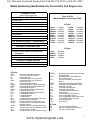
Model Numbering Identification for Tecumseh’s Full Engine Line
CURRENT CODE
(effective 2004 production)
Prior to 2004
Model Number Conversion Chart
1st Space - Valve Orientation
T = Two Cycle
O = Overhead Valve
4-Cycle
L = L-Head
2nd Space - Crank Orientation
V = Vertical
H = Horizontal
M = Multi-position
3rd, 4th and 5th Space - Displacement
LEV90
LEV120
HSSK50
HSSK55
VSK90
OHV135
OHV180
TVT691
VTX691
-
LV148EA
LV195EA
LH195SA
LH195SP
LV148SA
OV358EA
OV490EA
OV691EA
OV691EP
6th Space - Emissions Class
S = Snow Emission Compliant
OH195EA
OH195EP
OH195SA
OH195SP
LH318SA
LH358SA
OH318SA
OH358SA
OH318EA
2-Cycle
E = 50 State/Global Emissions Compliant
X = Not for sale in California, except exempt
applications
OHH60 OHH65 OHSK70 OHSK75 HMSK90 HMSK110 OHSK110 OHSK130 OHM110 -
TC300
HSK870
HSK600
AV520
-
TM049XA
TH139SP
TH098SA
TV085XA
7th Space - Engine Specifics
A = Standard (OHH50-60), (OHSK50-70)
P = Power Up (OHH65-70, OHSK75-775)
4-Cycle
ECH ECV HHH HHM -
HM HMSK HMXL HS HSSK HXL LAV LEV LH LV OH OHH OH195 OHM OHSK OHV OV OVM -
Exclusive Craftsman Horizontal
Exclusive Craftsman Vertical
Horizontal Shaft
Horizontal Heavy Duty (Cast Iron)
Horizontal Heavy Duty (Cast Iron)
(Medium Frame)
Horizontal Medium Frame
Horizontal Medium Frame (Snow King)
Horizontal Medium Frame (Extra Life)
Horizontal Small Frame
Horizontal Small Frame (Snow King)
Horizontal (Extra Life)
Lightweight Aluminum Frame Vertical
Low Emissions Vertical
L-Head Horizontal
L-Head Vertical
Overhead Valve Heavy Duty (Cast Iron)
Overhead Valve Horizontal
Overhead Valve Horizontal (195 cc's)
Overhead Valve Heavy Duty Horizontal
(Medium Frame)
Overhead Valve Horizontal (Snow King)
Overhead Valve Vertical (Medium Frame)
Overhead Valve Vertical
Overhead Valve Vertical (Medium Frame)
OVRM OVXL TNT TVEM TVM TVS TVT TVXL VVH VLV VLXL VM VSK VTX -
2-Cycle
TH TM TV -
Overhead Valve Vertical (Small Frame)
(Rotary Mower)
Overhead Valve Vertical (Medium
Frame) (Extra Life)
Toro ‘N’ Tecumseh (Toro Exclusive
Series)
Tecumseh Vertical European Model
Tecumseh Vertical (Medium Frame)
(Replaces V & VM)
Tecumseh Vertical Styled
Tecumseh Vertical Twin
Tecumseh Vertical (Extra Life)
Vertical Shaft
Vertical Heavy Duty (Cast Iron)
Vector Lightweight Vertical
Vector Lightweight Vertical (Extra Life)
Vertical Shaft (Medium Frame)
Vertical Snow King
Vertical Twin
Two Cycle Horizontal Shaft
Two Cycle Multiposition Operation
Two Cycle Vertical Shaft
www.mymowerparts.com
5
For Discount Tecumseh Engine Parts Call 606-678-9623 or 606-561-4983
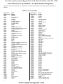
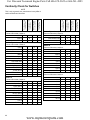
Cross Reference for Specification - To - Model Number Designation
This cross reference chart allows you to determine an engine Model Number if you only have the Specification
Number.
VERTICAL 4-CYCLE ENGINES
Specification
Number Series
10000
12000
20000
20500
21000
21800
22000
23000
23500
30000
33000
40000
42000
42600
42900
43000
43600
43700
43900
44000
44600
44800
46000
46600
48000
50000
50200
52600
52800
52900
53000
53600
53800
53900
54000
56000
56600
56800
56900
57000
57600
57800
57900
60000
61000
61600
61800
61900
62000
62100
63000
63200
63600
63900
66000
66100
70000
80000
90000
100000
125000
127000
127200
135000
6
Model
Number
TNT100
TNT120
LAV25, OVRM55
OVRM105
OVRM60
OVRM60
OVRM65, OVRM120
OV195EA (RM)
OV195EA (Utility)
LAV30
TVS75
LAV35
OVRM905 (Sears Only)
OVRM40, OVRM45 (Premier Engine)
OVRM40 (High Tech Look)
TVS90
TVS90 (Premier Engine)
TVS90, TVXL90
TVS90 (High Tech Look)
TVS100
TVS100 (Premier Engine)
TVS100
TVS90, TVXL90
TVS90
TVS90
V40
LAV40
OVRM50, OVRM55 (Premier Engine)
OVRM50, OVRM55
OVRM50, OVRM55 (High Tech Look)
TVS105
TVS105 (Premier Engine)
TVS105
TVS105 (High Tech Look)
TVXL105
TVS105, TVS & TVXL115
TVS105, TVS115 (Premier Engine)
TVS115
TVS105, TVS115 (High Tech Look)
TVS & TVXL115
TVS115 (Premier Engine)
TVS115
TVS115 (High Tech Look)
V50, TVM125
TVS & TVXL115
TVS & TVXL115
TVS115
TVS115
LAV50
LAV50 & TVS115
TVS120
TVS120, TVEM120
TVS120 (Premier Engine)
TVS120 (High Tech Look)
TVS120
TVS120
V60, TVM140
VH40
VH50
VH60
V70
VM70, TVM170
TVXL170
VH70
Specification
Number Series
145000
147000
148000
149000
150000
150200
150500
151000
151500
152000
157000
157200
157400
200000
202000
202200
202300
202400
202500
202600
202700
203000
203200
203500
203600
203800
204000
204200
204400
204500
204600
204800
206000
206200
206400
206600
206800
206900
208000
334000
334500
335000
338000
338500
340000
345000
346000
347000
348500
350000
355000
360000
361000
361400
361500
362000
400000
500000
501000
502000
502500
600400
600800
600900
Model
Number
ECV100
ECV105
VH80
VH100
V & VM80, TVM195
TVM & TVXL195
TVM195
ECV110, TVM195
TVM220
ECV120
VM100, TVM220
TVM & TVXL220
TVM220
OVM120
OVXL120, OVXL125
OVXL120 (I/C)
OHV11, OHV115
OVXL125
OHV115
OVXL125 (I/C)
OHV12, OVXL120 (Tec.1200)
OHV125, OVXL125 (Tec1250)
OHV13
OVXL125 (Tec.1250I/C), OHV13/135
OHV14/140
OHV145
OHV15/150
OHV16/160
OHV165
OHV155
OHV17/170
OHV175
OHV110
OHV115
OHV120
OHV125
OHV130
OHV135,OV358EA (Sm. Enduro)
OHV180,OV490EA (Lg. Enduro)
LEV90, LV148EA
VSK90, LV148SA
LEV100
LEV100
VSK100
LEV100
LEV100
LEV105
LEV105
VSK105
LEV115
LEV115
LEV115
LEV120
VSK120
LEV120, LV195EA (Utility)
LEV120, LV195EA (RM)
VLV40
ULT, VLV B24, VLXL50, & VLV126
ULT, VLV, VLXL55, & VLV126
ULT, VLV60, VLV65, & VLV126
VLV65, VLV66
TVT691
TVT691, OV691EA (Twin)
VTX691, OV691EP (Twin)
www.mymowerparts.com
For Discount Tecumseh Engine Parts Call 606-678-9623 or 606-561-4983
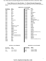
Cross Reference for Specification - To - Model Number Designation
This cross reference chart allows you to determine an engine Model Number if you only have the Specification
Number.
HORIZONTAL 4-CYCLE ENGINES
Specification
Number Series
15000
25000
26000
35000
35400
35800
36700
45000
45400
45800
46700
47000
55000
55200
55500
55700
55800
55900
65000
65300
67000
67500
68000
68500
69000
69500
71100
71500
71700
71800
71900
72000
72500
73500
75000
76000
85000
95000
105000
110000
115000
Model
Number
H22
H25
OHH45
H30
HSK30
H30
H30
H & HT35
HSK35
H35
H35
HXL35
H40
HS & HSSK40
HSK40
H40
H40
HSSK40
H50
HSK50
HS & HSSK50, LH195SA
HSSK55, LH195SP
OHH50
OHSK50
OHH55
OHSK55
OHH60, OH195EA
OHSK60
OHH65
OHH65, OH195EP
OHSK65
OHH70
OHSK70, OH195SA (Premium)
OHSK75, OH195SP (Premium)
H60
HSK60
HH40
HH50
HH60
HH80
HH100
Specification
Number Series
120000
130000
130200
132000
132500
140000
146000
155000
155000
155800
155900
156000
156500
159000
159900
159950
160000
170000
170000
175000
180000
190000
220000
221000
221200
221400
221600
221700
221800
222000
222300
222500
222700
223000
223400
223600
223700
223800
Model
Number
HH120
H70
HSK70
HM & HMSK70
HMXL70
HH70
ECH90
H & HM80
HMSK80
HM85
HM & HMSK85
HM90
HMSK90, LH318SA
HM & HMSK100, LH358SA
HMSK105
HMSK110
HH & OH140
HH150 & 160
OH160
OH120
OH180
HHM80
OHM120
OHSK110
OHSK80
OHSK90
OHSK100
OHSK110
OHSK115, OH318SA (Premium)
OHSK120
OHM90
OHM100
OHM110, OH318EA
OHSK90
OHSK110
OHSK120
OHSK125
OHSK130, OH358SA (Premium)
HORIZONTAL 2-CYCLE ENGINES
VERTICAL 2-CYCLE ENGINES
Specification
Number Series
Model
Number
Specification
Number Series
Model
Number
3600
670000
TC300, TM049XA
AV520, TV085XA
1720
8300
8700
HSK635, TH098SA
HSK850, TH139SA
HSK870, TH139SP
www.mymowerparts.com
7
For Discount Tecumseh Engine Parts Call 606-678-9623 or 606-561-4983
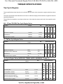
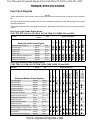
TORQUE SPECIFICATIONS
Two Cycle Engines
NOTES
Torque specifications listed should not be confused with the torque value observed on engines which have been
run.
The torque specifications take relaxation into account so sufficient clamping force exists after an engine has reached
operating temperature.
Torques listed are intended to cover highly critical areas. More extensive torques are found in the respective repair
manual.
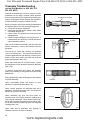
840 - 870 and TH139SA Two Cycle Engine Series
13.5-23
Flywheel Nut
360-420
41-47.5
Adapter Plate to Cylinder
160-220
18-25
HXL
120-204
Engine Designation
TH139SA
Crankcase to Cylinder
Nm
TVXL
Inch lbs.
Torque
TVS
Location
TC / TM Two Cycle Engine Series
9-11
Crankcase Cover to Crankcase
70-100
8-11
Flywheel Nut
190-250
21.5-28.5
Crankcase Cover to Cylinder
105
12
TM049
80-95
Engine Designation
TCH200/300
Cylinder to Crankcase
Nm
TC300
Inch lbs.
Torque
TC200
Location
Location
Inch lbs.
Torque
AV520/600
TV035XA
TVS600
AH/HSK600
TH098
AH520
Two Cycle Engine Series (AV520/600, TVS600, AH520, AH/HSK600, TH and TV)
Connecting Rod
40-50
4.5-5.5
Housing Base to Cylinder
80-120
9-13.5
Cylinder Head to Cylinder
100-140
11-16
Flywheel Nut AV (Point Ignition)
(670 Series AV520 and All AV600)
216-300
24.5-34
Flywheel Nut (C.D. Ignition)
264-324
30-36.5
8
Nm
Engine Designation
www.mymowerparts.com
For Discount Tecumseh Engine Parts Call 606-678-9623 or 606-561-4983
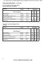
TORQUE SPECIFICATIONS
Four Cycle Engines
NOTES
Torque specifications listed should not be confused with the torque value observed on engines which have been
run.
The torque specifications take relaxation into account so sufficient clamping force exists after an engine has reached
operating temperature.
Torques listed are intended to cover highly critical areas. More extensive torques are found in the respective repair
manual.
Four Cycle Light Frame Engine Series
(TVS, TNT, ECV, LAV, LH, LV, LEV, H, HS, OH, OHH, OV, OVRM, VLV and VSK)
11-16
11-12.5
18-24
25-27
20.5-25
11-14.5
42-50
45-56.5
Four Cycle Medium Frame Engine Series
(TVM, TVXL, H, V, HM, LH, OH, OVM, OVXL, OHM, OHSK, OV and OHV)
160-180
200-220
200-240
220-240
180-240
160-210
65-80
110-130
15-20
170-210
75-130
15-20
40-65
100-130
110-140
400-550
600-800
18-20.5
22.5-25
22.5-27
25-27
20.5-27
18-24
7-9
12.5-14.5
2
19-24
8.5-14.5
2
4.5-7
11-14.5
12.5-16
45-62
68-90
OHV11-13,OHV110135, 206 Series
OHSK80-130
OHM120, OH318-358
OVM/OVXL,
OHV120-125
HM/HMSK70-100
LH318 - 358
TVM & TVXL
170-195-220
V70
H50-60
Aluminum Medium Frame Engines
Connecting Rod
Connecting Rod
Connecting Rod
Cylinder Head Bolts
Cylinder Head Bolts
Cylinder Head Bolts
Rocker Adj. Lock Screw
Rocker Arm Stud Lock Nut
Rocker Arm Hex Jam Nut
Rocker Arm Studs
Rocker Arm Box to Head
Rocker Box Cover
Rocker Box Cover (Four Screw)
Mounting Flange or Cylinder Cover
Mounting Flange or Cylinder Cover
Flywheel Nut
Flywheel Nut (External Ignition)
OHH / OH
Engine Designation
TVM125, 140
Nm
H70
Inch lbs.
Torque
Location
LEV / LV
VLV
OVRM. OV
HS/HSSK/
LH
H/HSK
OHV135-145 / OV358
203 Series
OHV15-18 / OV490
204 Series
100-140
95-110
160-210
220-240
180-220
100-130
500-600
400-500
ECV
Aluminum Light Frame Engines
Rocker Arm Stud Lock Nut
Connecting Rod
Cylinder Head
Cylinder Head
Cylinder Head
Mounting Flange or Cylinder Cover
Flywheel Nut (Cast Iron)
Flywheel Nut (Aluminum)
TNT
Engine Designation
TVS
Nm
LAV
Inch lbs.
Torque
Location
www.mymowerparts.com
9
For Discount Tecumseh Engine Parts Call 606-678-9623 or 606-561-4983
Torque Specifications - continued
Four Cycle Heavy Frame Engine Series
(Cast Iron Block HH, VH and OH)
Inch lbs.
Torque
Engine
Designation
Connecting Rod
86-110
10-12.5
Cylinder Head
180-240
20.5-27
Mounting Flange & Cylinder Cover
100-130
11-14.5
Rocker Arm Shaft to Box
180-220
20.5-25
Rocker Arm Box to Cylinder Head
80-90
9-10
Flywheel Nut
600-660
68-74.5
OH
Cast Iron Engines
VH
Nm
HH
Location
Four Cycle Large Frame Engine Series
(V-TWIN)
Connecting Rod
200-220
22.5-25
Cylinder Head Bolts
220-240
25-27
Rocker Arm Jam Nut
110-130
12.5-14.5
Rocker Arm Cover Mounting Screw
52
6
Mounting Flange/Cylinder Cover
240-260
27-29
Flywheel Nut
600-800
68-90
10
OV691
V-Twin Engines
Engine
Designation
VTX
Nm
TVT
Inch lbs.
Torque
Location
www.mymowerparts.com
For Discount Tecumseh Engine Parts Call 606-678-9623 or 606-561-4983
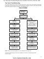
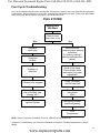
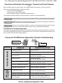
Two Cycle Troubleshooting
As an aid in troubleshooting any piece of equipment, interview the customer, and review conditions and symptoms
of the problem. Examine exterior for clues: leaks, excessive dirt, damaged or new parts. Follow safety precautions
when working with the fuel system. See page 2-J. Avoid Gasoline Fires.
FUEL SYSTEM
Engine Will
Not Start
Check if spark
plug is wet or dry
Wet
Defective
spark plug
Dry
Restricted
air filter
Review with customer
priming or choking
procedure
(3-5 primes, if equipped,
waiting 2 seconds
between each prime)
Improper fuel mix
or stale fuel
Carburetion problem*
(bad bowl gasket)
Sheared or partially
sheared flywheel key
Check fuel supply
and fuel cap vent
Carburetion problems
due to flooding, over
priming, etc.*
Restriction in
fuel system
(filter, screen)
Ignition System
Poor
compression
Crankcase seals
or gaskets leaking
Damaged reed, port
plugs, seals or gaskets
NOTE: Refer to Technician's Handbook, Form No. 692508 for a more detailed list.
*Carburetor Troubleshooting use Technician's Handbook or Carburetor Troubleshooting Booklet,
Form No. 695907.
www.mymowerparts.com
11
For Discount Tecumseh Engine Parts Call 606-678-9623 or 606-561-4983
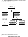
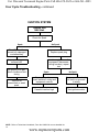
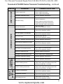
Two Cycle Troubleshooting - continued
IGNITION SYSTEM
Engine Will
Not Start
Check for Spark
Spark
No Spark
Check flywheel for
correct key, damaged
key or key adaptor
Replace spark plug
Set proper air gap on
external coil
Set proper point gap,
check condensor and
timing (if equipped)
Test coil for
intermittent or weak
spark
Check electric starter
if applicable
Isolate engine from all
equipment (disconnect
wiring harness), repeat
test
Spark
No Spark
Equipment problem,
check switches, wiring and
equipment controls
Engine problem, check
for shorts or grounds
in wiring
Parasitic load too high
Test ignition module
NOTE: Refer to Technician's Handbook, Form No. 692508 for a more detailed list.
12
www.mymowerparts.com
For Discount Tecumseh Engine Parts Call 606-678-9623 or 606-561-4983
Four Cycle Troubleshooting
As an aid in troubleshooting any piece of equipment, interview the customer, and review conditions and symptoms
of the problem. Examine exterior for clues: leaks, excessive dirt, damaged or new parts. Follow safety precautions
when working with the fuel system. See page 2-J. Avoid Gasoline Fires.
FUEL SYSTEM
Engine Will
Not Start
Check if spark
plug is wet or dry
Wet
Defective
spark plug
Restricted
air filter
Dry
Review with the
customer proper priming
procedure
(3-5 primes, waiting 2
seconds between each
prime)
Improper or
stale fuel
If equipped with a choke,
check for full travel.
Check throttle cable
and control for proper
adjustment.
Exhaust ports plugged
Check fuel supply
and fuel cap vent
Carburetion problems
due to flooding, over
priming, etc.*
Restriction in
fuel system
(filter)
Ignition System
Carburetion problem*
(bad bowl gasket)
Poor
Compression
NOTE: Refer to Technician's Handbook, Form No. 692509 for a more detailed list.
*Carburetor Troubleshooting, use Technician's Handbook or Carburetor Troubleshooting Booklet, Form No.
695907.
www.mymowerparts.com
13
For Discount Tecumseh Engine Parts Call 606-678-9623 or 606-561-4983
Four Cycle Troubleshooting - continued
IGNITION SYSTEM
Engine Will
Not Start
Check for Spark
Spark
No Spark
Check flywheel for
correct key, damaged
or sheared key
Replace spark plug
Set proper air gap on
external coil
Set proper point gap,
check condensor and
timing
Test coil for
intermittent or weak
spark
Isolate engine from all
equipment (disconnect
wiring harness), repeat
test
Spark
No Spark
Equipment problem,
check switches, wiring and
equipment controls
Engine problem, check
for shorts or grounds
in wiring
Parasitic load too high
Test ignition module
NOTE: Refer to Technician's Handbook, Form No. 692509 for a more detailed list.
14
www.mymowerparts.com
For Discount Tecumseh Engine Parts Call 606-678-9623 or 606-561-4983
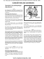
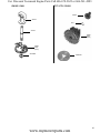
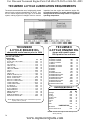
CARBURETORS AND GOVERNORS
Tecumseh 2-Cycle Diaphragm
Adjustments
NOTE
For meeting emission requirements, some carburetors
have fixed-main or idle jets. The absence of the
adjustment screw indicates fixed jets and no adjustment
is necessary.
Diaphragm-Dual Adjustment
Turn mixture adjusting screws in finger tight to the closed
position, then one (1) turn out from closed position. This
setting is approximate. This will allow the engine to be
started so the carburetor can be fine tuned.
Start the engine and let it warm up for approximately
3-5 minutes. Do not adjust the carburetor when the
engine is cold.
Set the throttle control to idle. If it is a fixed speed
type, manually hold the throttle against the idle speed
adjustment screw.
The throttle lever must be held against the crack
screw for low speed adjustments or all adjustments
will be incorrect and cause poor performance and
unsatisfactory operation.
With the engine idling and throttle lever against the idle
speed regulating screw, turn the low speed adjustment
screw slowly clockwise from the NORMAL setting until
the engine falters. Remember this location. Turn the
screw counterclockwise until engine just starts to sputter
or drops in R.P.M. Remember this location. Turn the
screw clockwise until it is halfway between your first
position where the engine faltered and your last position
where the engine started to sputter. This will be the
optimum low speed setting on your carburetor.
Next run the engine at governed speed. The high speed
adjustments are made basically the same as the low
speed adjustments, with the exception of the settings
being made 1/8 of a turn at a time, from the NORMAL
settings.
IDLE MIXTURE
SCREW
MAIN MIXTURE
SCREW
NOTE: If no tension
spring is present, it
may be a fixed jet.
1
Start the engine and let it warm up for approximately
3-5 minutes. Do not adjust the carburetor when the
engine is cold.
Set the throttle control to idle. If it is a fixed speed
type, manually hold the throttle against the idle speed
adjustment screw.
NOTE
If the engine falters or stops after the choke lever is
moved to the "OFF" position, open the mixture adjusting
screw 1/4 turn (counterclockwise) and restart the
engine.
With the engine running, place the speed control in
the "slow" position to make mixture adjustments. Turn
the mixture screw slowly clockwise from the NORMAL
setting until the engine falters. Remember this location.
Turn the screw counterclockwise until the engine just
starts to sputter or drops in R.P.M. Remember this
location. Turn the screw clockwise until it is halfway
between your first position where the engine faltered and
your last position where the engine started to sputter.
This will be the optimum setting on your carburetor.
NOTE
It may be necessary to re-check the idle mixture
adjustment after performing the high speed
adjustment.
Diaphragm-Single Adjustment
Turn the mixture adjustment screw finger tight to the
closed position, then one (1) turn out from the closed
position. This setting is approximate and will allow
the engine to be started so the carburetor can be finetuned.
www.mymowerparts.com
15
For Discount Tecumseh Engine Parts Call 606-678-9623 or 606-561-4983
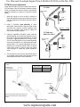
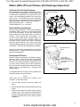
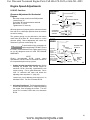
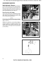
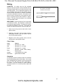
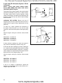
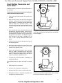
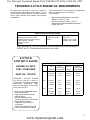
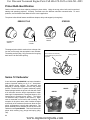
TC/TM Governor Adjustment
Three different styles of governor systems are used on
TC/TM engines. Use the following illustrations (diags.
2 and 3) to identify the governor system used and the
following procedure to adjust the governed engine
speed.
TC TYPE I
Spring Hooked
In Notch
1. Allow the engine to run for at least 5 minutes to
reach the operating temperature. Make sure the air
filter (if equipped) is clean and the choke is in the off
position.
2. Using a Vibratach (part #670156) or other
tachometer, determine the engine's R.P.M at idle
and wide open throttle. Consult microfiche card
#30 or the computer parts lookup to obtain the
recommended engine speeds.
3. Using the applicable illustration, either bend the
speed adjusting lever toward the spark plug end of
the engine to decrease high speed R.P.M., or bend
the lever in opposite direction to increase R.P.M.
On TC Type II/TM engines, turn the speed adjusting
screw out to increase or in to decrease engine high
speed R.P.M. If the speed adjustment screw is
turned out to increase the engine R.P.M., the speed
control lever must be moved to allow the speed
control plunger to contact the speed adjustment
screw.
Speed
Adjusting
Lever
Decrease
Increase
TC TYPE I and
EARLY TC TYPE II
Spring Hooked
In Notch
Speed
Adjusting
Lever
4. The low speed is set by moving the throttle control
to the lowest speed position and adjusting the low
speed adjustment screw on the carburetor.
2
TYPE II
Spring Color
Decrease (IN)
Increase (OUT)
Speed Adjusting Screw
Spring Position
Orange or Green
1
Pink, Red, or Black
2
Spring Position 1
Spring Position 2
Adjust governed high speed with speed control
plunger pulled back against speed adjustment
screw
Speed Adjusting Screw
16
www.mymowerparts.com
3
For Discount Tecumseh Engine Parts Call 606-678-9623 or 606-561-4983
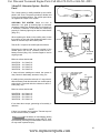
Walbro (WTA, WT) and Tillotson (HU) Diaphragm Adjustment
Carburetor Pre-Set and Adjustment
Both the Walbro and the Tillotson carburetors used on
TC engines have non-adjustable main mixture jets. Only
the idle mixture is adjustable by turning the idle mixture
screw. Use the following procedure to pre-set the idle
mixture screw. Turn the idle mixture screw (clockwise)
finger tight to the closed position, then turn the screw
counterclockwise to obtain the proper preset (diag. 4).
Walbro Model WTA, WT 1 - 1-1/8 turns
Tillotson Model HU 1-1/4 - 1-3/8 turns
IDLE SPEED ADJUSTMENT
SCREW
Final Idle Mixture Adjustment
Start the engine and allow it to reach normal operating
temperature (after 3-5 minutes). As the speed control
is set at the idle position, turn the idle mixture screw
slowly clockwise until the engine R.P.M. just starts to
decrease. Stop and note this screw position. Turn
the idle mixture screw slowly counterclockwise, the
engine will increase in R.P.M. Continue to slowly turn
the screw until the engine R.P.M. starts to decrease.
Note this position and turn the mixture screw back
clockwise halfway between the two engine R.P.M. drop
off positions. The idle mixture adjustment is complete.
IDLE MIXTURE SCREW
Some carburetors come equipped with a main mixture
adjusting screw. To adjust the main mixture, follow the
steps for idle adjustment.
Emissionized Tillotson
Similar in design and operation, the Tillotson emission
carburetor uses a fixed main jet with an adjustable
idle. The idle circuit has a limiter cap to prevent over
richening. The cap is locked onto the adjustment screw
in a rich position, allowing only a leaner adjustment.
The main is fixed on these, which means that the main
mixture limiter is non-functional on Tecumseh built
engines (diag. 5).
In compliance with E.P.A. and C.A.R.B. regulations the
following procedure must be followed.
4
IDLE MIXTURE LIMIT
SCREW
FIXED MAIN
(MIXTURE SCREW
NOT FUNCTIONAL ON
MOST TECUMSEH BUILT
ENGINES)
IDLE SPEED
ADJUSTMENT
SCREW
5
NOTE
These caps can be removed for servicing of the
carburetor. Follow these steps.
1. Turn the caps clockwise until they contact the
stops.
2. Remove the caps with a pointed instrument such as
an awl.
3. Then turn the screws in until softly seated, note the
number of turns. The screws must be reinstalled to
this same static setting. Replacement of the caps is
required to maintain E.P.A. and C.A.R.B. emission
compliance.
www.mymowerparts.com
17
For Discount Tecumseh Engine Parts Call 606-678-9623 or 606-561-4983
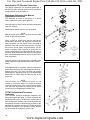
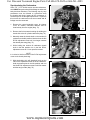
Emissionized TC/Tilloston Carburetor
The Tillotson carburetor is an emissions grade carb. It
has a married idle and high speed circuitry with limited
jet adjustments on the idle (diag. 6).
Emissions Carburetor Idle Mixture
Adjustment Procedures
The carburetor is preset at the factory at a normal
setting required for initial engine operation.
Allow the engine to reach normal operating temperature
(after 3-5 minutes).
Set the engine speed control in the idle position.
NOTE
With the engine at idle speed, it must be less than 2400
R.P.M. for accurate adjustment.
Using a small tip screw driver that fits through the
access hole in the limiter cap, adjust the mixture screw
slowly clockwise until the engine R.P.M. just starts to
decrease. Stop and note this screw position. Turn the
idle mixture screw slowly counterclockwise. As the
engine increases R.P.M. continue to slowly turn the
screw counterclockwise until the engine R.P.M. starts to
decrease. Note this position and turn the mixture screw
back clockwise halfway between the two engine R.P.M.
drop off positions.
Verify the engine will accelerate from low speed to high
speed and that the idle speed remains at the desired
setting.
6
Once adjustments are complete, center the adjustment
limiter cap between the two stops and press inward to
engage the limiter. The limiter will snap into position
and engage the adjusting screw. All future adjustments
should now be made using the adjusting slot in the
limiter cap.
NOTE
Once the limiter cap is snapped into place it is not
possible to remove the limiter or to adjust the mixture
screw beyond the limits of the limiter assembly. Make
sure that initial adjustments are made per the above
procedure prior to engaging the limiter cap.
TC/TM, Emissionized Tecumseh
Carburetor
The Tecumseh emissions diaphragm carburetor has
fixed main and idle jets (diag. 7). It uses a married idle
and high speed circuitry. The idle has a metering jet that
can be removed for cleaning. It is covered by a small cap
that must be removed to expose the jet for servicing. No
adjustments or presets are required. The idle jet should
be turned until tight 5-8 inch pounds (0.5 Nm), and the
cap should then be installed to cover the jet.
18
www.mymowerparts.com
7
For Discount Tecumseh Engine Parts Call 606-678-9623 or 606-561-4983
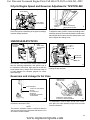
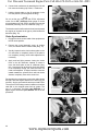
2-Cycle Engine Speed and Governor Adjustments: TVS/TVXL840
IDLE SPEED
ADJUSTMENT
HIGH SPEED
ADJUSTMENT
HOLDING
SCREW
8
Linkage Location
To aid in the proper reassembly of the governor linkage,
mark the linkage locations.
STATIC GOVERNOR
ADJUSTMENT SCREW
9
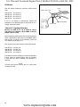
Static Governor Adjustment
To adjust the static governor, loosen the holding screw,
rotate the governor arm and slotted shaft in the direction
that will open the throttle to the wide open position, and
then re-tighten the holding screw.
HSK/HXL840-870/TH139
IDLE RPM
ADJUSTMENT
SCREW
HIGH
SPEED RPM
ADJUSTMENT
SCREW
INCREASE
DECREASE
10
The HXL840 - 870 Series with variable speed control
have the following adjustments. Idle speed is set at
the carburetor crack screw. High speed is set with the
screw shown above. Always check Microfiche card 30
or Parts Manager Pro computer program for correct
speed settings.
BEND TAB
11
R.P.M. adjustment of fixed speed models is done by
bending the tab as shown.
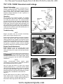
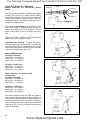
Governors and Linkage for Air Vane
BEND TAB TO
ADJUST RPM
IN
DE CR
CR EA
EA SE
SE
VANE ASSEMBLY
TO ADJUST HIGH-SPEED
ROTATE
CLOCKWISE TO
INCREASE
COUNTERCLOCKWISE
TO DECREASE
12
Rotate sleeve clockwise to increase R.P.M., counterclockwise to decrease R.P.M.
NOTE
The sleeve is serrated to rotate in a clockwise direction
and must be raised using the sleeve tabs before it can
be rotated counterclockwise.
HORIZONTAL FIXED SPEED
PLASTIC AIR VANE GOVERNOR
13
To disassemble, remove choke shutter with needlenose pliers; the vane assembly may then be removed
from the carburetor.
www.mymowerparts.com
19
For Discount Tecumseh Engine Parts Call 606-678-9623 or 606-561-4983
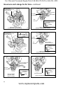
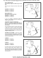
Governors and Linkage for Air Vane - continued
ADJUST RPM BY
LOOSENING SCREW AND
SLIDING BRACKET
IN
DE CR
CR EA
EA SE
SE
HIGH SPEED
RPM
ADJUSTMENT
IDLE RPM
ADJUSTMENT
IDLE
MIXTURE
THIS HOLE NOT
PRESENT ON ALL
MODELS
SPRING
HORIZONTAL FIXED SPEED
(ALUMINUM AIR VANE GOVERNOR)
ADJUST RPM BY
LOOSENING SCREW AND
SLIDING BRACKET
14
VERTICAL ENGINE
VARIABLE SPEED-REMOTE CONTROL
15
SPRING
GOVERNOR
LINK
IN
DE CR
CR EA
EA SE
SE
IDLE RPM
ADJUSTMENT
HIGH SPEED
RPM ADJUSTMENT
IDLE
MIXTURE
THIS HOLE NOT
PRESENT ON ALL
MODELS
SPRING
HORIZONTAL FIXED SPEED
16
VERTICAL ENGINE
FIXED SPEED-REMOTE CONTROL
17
HIGH SPEED RPM
ADJUSTMENT
IDLE RPM
ADJUSTMENTS
THIS HOLE NOT
PRESENT ON
ALL MODELS
VERTICAL ENGINE
VARIABLE SPEED
MANUAL CONTROL
20
SPRING
18
THIS HOLE NOT
PRESENT ON ALL
MODELS
RPM ADJUSTMENT
VERTICAL ENGINE FIXED SPEED
www.mymowerparts.com
SPRING
19
For Discount Tecumseh Engine Parts Call 606-678-9623 or 606-561-4983
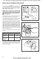
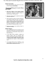
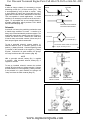
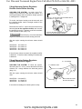
4-Cycle Static Governor
Adjustments
The purpose of making a static governor adjustment is
to remove all free-play between the governor spool and
the carburetor (diag. 20). Any free-play here will result
in hunting/surging or erratic running. After completing
this procedure, always re-check the engine speeds
using the steps outlined in the following pages.
SPRING
CHOKE
THROTTLE
GOVERNOR
ROD
To set the static governor, do the following:
NO FREE
PLAY
1. Be sure the engine is stopped or damage may
occur.
GOVERNOR
SPOOL
2. If equipped with a throttle control, place the throttle
in the high speed position.
3. Loosen the governor clamp or screw.
WIDE OPEN
THROTTLE
4. Hold the governor arm and link in the W.O.T. (wide
open throttle) position, then rotate the shaft or shaft/
clip assembly in the same direction and tighten the
screw.
CLOSED
THROTTLE
20
THROTTLE
GOVERNOR
SHAFT
WEIGHTS
SPRING
GOVERNOR
LEVER
GOVERNOR
SPOOL
GOVERNOR
GEAR
GOVERNOR
CLAMP
21
www.mymowerparts.com
21
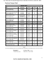
For Discount Tecumseh Engine Parts Call 606-678-9623 or 606-561-4983
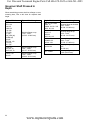
Governor Shaft Pressed In
Depth
When assembling governor shaft into a flange or cover
mounting boss, refer to this chart for exposed shaft
length.
Engine Model
Exposed Shaft Length
ECH 90
ECV 100
H30, 35
HS40, 50
LAV (all)
LEV (all)
LV (all)
OH, OHH (all)
OVRM (all)
OV195
TNT100, 120
TVS (all)
VLV (all)
Mounting flange to top
1.319 - 1.334"
(33.502 - 33.883 mm)
TVM (all)
V50, 60, 70
VH50, 60, 70
Mounting flange to top
1.581 - 1.596"
(40.157 - 40.538 mm)
HH100, 120
VH100
Mounting flange to top
1.016 - 1.036"
(25.806 - 26.314 mm)
22
Engine Model
Exposed Shaft Length
H50, 60, 70, LH195
HH60, 70
HHM80, LH318 - 358
HM70, 80, 100
Mounting flange to shoulder
1.283 - 1.293"
(32.588 - 32.842 mm)
OV358-OV490
OHV11-17
OVM120
OVXL120, 125
Mounting flange to top
1.350 - 1.365"
(34.290 - 34.671 mm)
OHM90-120
OHSK90-130
OH318 - 358
Mounting flange to top
1.085 - 1.100"
(27.559 - 27.940 mm)
OH120-180
Mounting flange to top
1.00"
(25.400 mm)
TVT - OV691
Mounting flange to top
1.196" (30.378 mm)
www.mymowerparts.com
For Discount Tecumseh Engine Parts Call 606-678-9623 or 606-561-4983
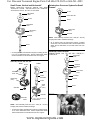
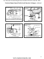
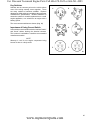
Small Frame, Vertical and Horizontal*
Models: LAV35,40,50 - H25,30,35 - HS40,50 - HSK - HSSK
-TNT100,120 - ECH90 - TVS75,90,105,115,120 - OVRM ALL
- ECV100,105,110,120 - ALL LEV, LV and LH195
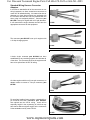
Retainerless Governor System for Small
Frames*
SPOOL
RETAINING
RING
UPSET ROLLED
SPOOL
SHAFT
RETAINING
RING
GEAR ASSY.
(GOV.)
GEAR ASSY.
(GOV.)
WASHER
WASHER
NOTE: Gear assembly must have .010 - .020 (.25 - .50 mm)
end play after shaft is installed into flange.
* As of August 1992, all small frame engines, including
VLV40-6.75, use a retainerless shaft. Service replacement
shafts will be retainerless for all small frame and VLV
engines.
SHAFT
* As of August 1992, all small frame engines, including VLV406.75, use a retainerless shaft. Service replacement shafts
will be retainerless for all small frame and VLV engines.
Medium Frame Vertical
Models: TVM125, 140, 170, 195, 220 - V50,60,70 VH50,60,70
RETAINING
RING
VLV*40, 50, 55, 60, 65, 66
TYPE I
SPOOL
SPOOL
TYPE II
WASHER
RETAINING
RING
GEAR ASSY.
(GOV.)
SPOOL
RETAINING
RING
UPSET
RETAINER
GEAR ASSY.
(GOV.)
WASHER
SPACER
SHAFT
GEAR
ASSY.
(GOV.)
WASHER
WASHER
IDLER
GEAR
SHAFT
OV195
.010 - .020 (.25-.50 mm)
CLEARANCE
NOTE: Gear assembly must have .010 - .020 (.25 - .50 mm)
end play after shaft is installed into flange.
* As of August 1992, all small frame engines, including VLV406.75, use a retainerless shaft. Service replacement shafts
will be retainerless for all small frame and VLV engines.
www.mymowerparts.com
23
For Discount Tecumseh Engine Parts Call 606-678-9623 or 606-561-4983
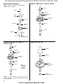
Medium Frame Horizontal
OHM120 - OHSK 80-130 - OH318 - OH358
Models: HH60,70 - H50,60,70 - HM70,80,100 HMSK - LH318 - LH358
SPOOL
SHAFT
WASHER
RETAINING
RING
ROD
ASSY.
(GOV.)
GEAR ASSY.
(GOV.)
SPOOL
WASHER
WASHER
RETAINING
RING
GEAR
ASSY.
(GOV)
SHAFT
BRACKET
SCREWS
OVM120, OVXL120, 125 - OHV11-17 OV358 - OV490
OH120, 140, 160, 180
SPOOL
SPOOL
WASHER
RETAINING
RING
WASHER
GEAR ASSY.
(GOV.)
WASHER
SPACER
NOTE;
SPACER MAY
BE PART OF
THE GEAR
ASSEMBLY.
GEAR &
SHAFT ASSY.
(GOV.)
SHAFT
WASHER
(captured under gear)
NOTE: On models OHV13.5-17, the spacer is cast as
part of the governor gear with the washer placed below
the gear assembly.
24
www.mymowerparts.com
For Discount Tecumseh Engine Parts Call 606-678-9623 or 606-561-4983
OH195 / OHH
TVT / VTX / OV691
SPOOL
SPOOL
CLIP
SHAFT
GEAR
ASSY.
(GOV.)
GEAR
ASSY.
(GOV.)
WASHER
www.mymowerparts.com
WASHER
25
For Discount Tecumseh Engine Parts Call 606-678-9623 or 606-561-4983
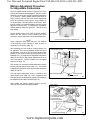
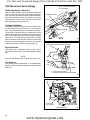
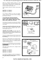
Engine Speed and Mixture Adjustments
NOTE
Starting and operating problems may exist when engines
are used at high elevations (over 4,000 feet above sea
level). In cases where a fixed main carburetor is used,
refer to Bulletin 110 for correction.
Engines which are identified as compliant with
CARB (California Air Resources Board) or EPA (US
Environmental Protection Agency) regulations can
NOT be changed from their factory jetting unless
specifically authorized.
IDLE
(Low Speed)
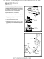
Before making any speed or carburetor adjustments be
sure to adjust the governor and control bracket.
To adjust the speed control bracket, determine whether
the carburetor is an adjustable type, then proceed.
Some carburetors may have a choke lever which is
operated by the speed control bracket. To adjust the
speed control bracket for full choke operation, loosen
the speed control bracket mounting bolts and move the
speed control lever to the high speed/full choke position.
Next, insert a small piece of wire through the hole in the
speed control bracket, choke actuating lever, and the
choke lever (diag. 23). When all three holes are aligned
tighten the mounting bolts.
MAIN (High Speed)
NON-ADJUSTABLE NO
CHOKE PRIMER
ADJUSTABLE MIXTURES,
CHOKE
SPEED CONTROL
MOUNTING BOLTS
22
SMALL WIRE (DRILL BIT)
HOLE IN BRACKET
HOLE IN SPEED
CONTROL CHOKE
ACTUATING LEVER
It may be necessary to preset the carburetor mixture
screws.
HOLE IN CHOKE
LEVER
Tecumseh Carburetors
Engine Model
Main Pre-set
Idle Pre-set
All models
with float-type
carburetors
1-1/2 turn
1 turn
1 turn
1 turn
All models with
diaphragm-type
carburetors
23
SPEED CONTROL MOUNTING BOLTS
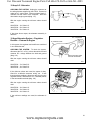
Some speed control brackets are adjusted by loosening
the speed control bracket mounting bolts and sliding
the bracket all the way to the right and re-tightening the
mounting bolts (diag. 24).
24
26
www.mymowerparts.com
For Discount Tecumseh Engine Parts Call 606-678-9623 or 606-561-4983
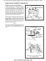
Mixture Adjustment Procedure
for Adjustable Carburetors
Once the speed control bracket is adjusted, the main
and idle fuel mixtures can be adjusted. Start the engine
and allow it to warm up to normal operating temperature
(3 - 5 minutes). Set the speed control to the HIGH or
FAST position, then turn the main mixture adjustment
screw in (clockwise) slowly until the engine begins to
run erratic (lean). Note the position of the screw. Now,
turn the screw out (counterclockwise) until the engine
begins to run erratic (rich). Turn the screw in (clockwise)
midway between these two positions. This will be the
best setting.
Set the speed control to the IDLE or SLOW position.
Adjust the idle mixture screw following the same
procedure used to adjust the main mixture adjustment.
CAPPED JET
TYPICAL NON ADJUSTABLE CARBURETOR
NOTE
Some carburetors have fixed main jets. The absence
of the adjusting screw indicates a fixed jet and no
adjustment is necessary (diag. 25).
After adjusting the fuel mixtures, engine speeds can
be adjusted. The correct operating speeds are found
on Microfiche card 30 of the Tecumseh Master Parts
Manual, or the computer parts look-up program (Parts
Manager Pro). On engines with adjustable carburetors
(diag. 26 and 27) the high speed adjustment will be in
one of two places. The first location is on the speed
control lever (diag. 26).
HIGH SPEED
ADJUSTMENT SCREW
25
LOW SPEED
ADJUSTMENT SCREW
The second is on a bracket located between the blower
housing and the speed control (diag. 27). Low speed
is adjusted by the throttle crack screw on the carburetor
(diag. 26 and 27).
The high speed adjustment screw is located on the
speed control lever (diag. 28) Some carburetors are
fixed speed and are adjusted by bending the adjusting
tab attached to the intake manifold (diag. 30).
MAIN MIXTURE
SCREW
26
HIGH SPEED
ADJUSTMENT
SCREW
LOW SPEED
ADJUSTMENT SCREW
After setting the engine speeds recheck the fuel
mixtures, then recheck the engine speeds.
IDLE MIXTURE SCREW
COUNTERCLOCKWISE
TO INCREASE SPEED
CLOCKWISE TO
DECREASE SPEED
IDLE
MIXTURE
SCREW
MAIN MIXTURE SCREW
www.mymowerparts.com
27
27
For Discount Tecumseh Engine Parts Call 606-678-9623 or 606-561-4983
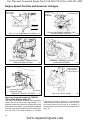
Common Engine Speed Controls and Governor Linkages
LOW SPEED
ADJUSTMENT SCREW
HIGH SPEED
ADJUSTMENT SCREW
LOW SPEED TAB
HIGH SPEED TAB
HIGH SPEED
PIN POSITION
DECREASE
TOOL
(670326)
28
BEND
BEND
TVS, LEV SNAP IN CONTROL
BEND
BEND
SPEED ADJUSTMENT TAB
INCREASE
29
TO INCREASE SPEED
TO DECREASE SPEED
TO INCREASE SPEED
TO DECREASE SPEED
BEND CONTROL
BRACKET TO SET RPM
30
THROTTLE CRACK SCREW
IDLE
MIXTURE
SCREW
MAIN MIXTURE SCREW
31
GOVERNOR
ADJUSTING
LEVER
HIGH SPEED
ADJUSTMENT
SCREW
LOW SPEED
ADJUSTMENT SCREW
32
28
VERTICAL ENGINES
OV195 LINKAGE
www.mymowerparts.com
33
For Discount Tecumseh Engine Parts Call 606-678-9623 or 606-561-4983
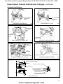
Common Engine Speed Controls and Governor Linkages - continued
HIGH SPEED RPM
ADJUSTMENT SCREW
HIGH SPEED RPM
ADJUSTMENT
SCREW
IDLE SPEED
CRACK SCREW
TVS, LEV AND LV ENGINE"S WITH PRIMER STYLE
CARBURETOR AND REMOTE SPEED CONTROL
34
BEND
BEND
VERTICAL SHAFT ENGINES
NOTE:
ON REMOTE CONTROL
THIS WILL NOT BE
PRESENT
TO INCREASE SPEED
TO DECREASE SPEED
35
HIGH SPEED ADJUST
LOW SPEED ADJUST
TNT 100 VERTICAL ENGINES
36
TYPICAL LATE MODEL LIGHT WEIGHT VERTICAL
37
WITH ADJUSTABLE SPEED CONTROL
www.mymowerparts.com
29
For Discount Tecumseh Engine Parts Call 606-678-9623 or 606-561-4983
VLV Governor and Linkage
TWIST COUNTERCLOCKWISE
TO DISCONNECT
Static Adjustment - Governor
With the engine stopped, loosen the screw holding the
governor lever to the governor shaft. Push the governor
lever up to move the carburetor throttle plate to the wideopen throttle position. Rotate the governor rod in the
same direction. Hold the lever and rod in this position
while tightening the screw (diag. 38).
GOVERNOR SPRING
Linkage Installation
The solid link is always connected from the throttle lever
on the carburetor to the lower hole on the governor
lever. The shorter bend has to be toward the governor.
The governor extension spring is connected with the
spring end hooked into the upper hole of the governor
lever and the extension end hooked through the speed
control lever. To remove the governor spring, carefully
twist the extension end counterclockwise to unhook the
extension spring at the speed control lever. Do not bend
or distort the governor extension spring (diag. 38).
SHORT BEND
LONG BEND
VLV
38
HIGH SPEED ADJUSTMENT
COUNTERCLOCKWISE INCREASES SPEED
Speed Controls
This engine has an adjustable speed control. Never
exceed the manufacturer's recommended speeds.(diag.
39).
NOTE
Governor adjustment screw will be a Torx head (T-10).
Fixed Speed
High speed governor adjustment is accomplished by
bending a tab to increase and decrease engine R.P.M.
(diag. 40).
LOW SPEED ADJUSTMENT
COUNTERCLOCKWISE INCREASES SPEED
39
TOOL 670326
HIGH SPEED
ADJUSTMENT
BEND
BEND
TO INCREASE SPEED
TO DECREASE SPEED
FIXED SPEED
30
www.mymowerparts.com
40
For Discount Tecumseh Engine Parts Call 606-678-9623 or 606-561-4983
Engine Speed and Mixture Adjustments
Medium Frame Vertical Shaft Engines
To adjust high speed on an up/down control (diag.
41) bend the adjustment tab. Low speed is adjusted
by a screw at the bottom of the control bracket. Both
the governor override system and the up/down speed
control have a governed idle. On these systems it is
important to also adjust the throttle crack screw. To
adjust the throttle crack screw use your finger to hold
the throttle shutter tight against the throttle crack screw
and adjust the engine speed to approximately 600
R.P.M. less than the recommended low speed.
The idle speed is adjusted by turning the idle speed
screw clockwise to increase engine R.P.M. and
counterclockwise to decrease R.P.M. Use tool part
#670326 to adjust the high speed engine R.P.M. Place
the slotted end of the tool onto the adjustment tab and
bend the tab to the left (toward the spark plug end) to
increase engine R.P.M. (diag. 42).
HIGH SPEED ADJUSTMENT TAB
BEND
BEND
THROTTLE CRACK
SCREW
IDLE MIXTURE
SCREW
TO INCREASE SPEED
TO DECREASE SPEED
MAIN MIXTURE
SCREW
NOTE
Be sure that the throttle cable has full travel from wide
open throttle to full choke. Hard Starting could result
if the cable is not properly adjusted to allow for full
choke.
LOW SPEED
ADJUSTMENT
SCREW
41
CHOKE HOOKUP
HIGH SPEED
ADJUSTMENT
TAB
THROTTLE
LINK HOOKUP
ALIGNMENT
HOLE
GOVERNED
IDLE SPEED
SCREW
CHOKE LEVER
AIR GAP
(.040 - .070")
(1.0 - 1.8 mm)
BEND TAB TO
ADJUST
TOOL #670326
IDLE SPEED
CRACK SCREW
IDLE MIXTURE
SCREW
TVXL220, OHV 11-18, OV358EA, OV490EA
STYLE SPEED CONTROL
www.mymowerparts.com
42
31
For Discount Tecumseh Engine Parts Call 606-678-9623 or 606-561-4983
Engine Speed Controls and Governor Linkages
HIGH SPEED
PIN POSITION
LOW SPEED TAB
HIGH SPEED TAB
NOTE: ON REMOTE
CONTROL THIS
WILL NOT
BE PRESENT
HIGH SPEED ADJUST
LOW SPEED ADJUST
DECREASE
INCREASE
LEV, LV / TVS, OVRM SNAP IN CONTROL 43
TYPICAL LIGHTWEIGHT VERTICAL WITH
MANUAL SPEED CONTROL
44
TYPICAL LIGHTWEIGHT VERTICAL WITH
REMOTE SPEED CONTROL
45
STANDARD TVM ENGINE WITHOUT
GOVERNOR OVERRIDE
46
SPEED CHANGES
APPROXIMATELY
200 RPM PER SLOT
MAIN MIXTURE
SCREW
GOVERNOR ADJUSTING
SCREW (LOW SPEED)
HIGH SPEED
OVM/OVXL,TVM 170, 195 & 220
Governor Override System for TVM170,
195 and 220 Engines (diag. 47)
47
This system will be found starting on 1985 production
models and will not retrofit onto older engines. It is
designed to allow the governor to regulate the low and
high speeds of the engine. The high speed is adjusted
at the top screw of the override lever; to increase R.P.M.
turn the screw out (counterclockwise), to decrease
32
OHV 11-18, OV358 - OV490
48
R.P.M. turn the screw in (clockwise). The low speed
is adjusted at the bottom screw of the override lever;
to increase R.P.M. turn the screw in or clockwise, to
decrease R.P.M. turn the screw out or counterclockwise
(diag. 47).
www.mymowerparts.com
For Discount Tecumseh Engine Parts Call 606-678-9623 or 606-561-4983
Engine Speed Controls and Governor Linkages - continued
Horizontal Shaft Engines
IDLE SPEED
CRACK SCREW
IDLE SPEED
CRACK SCREW
HIGH SPEED RPM
ADJUSTMENT
SCREW
HORIZONTAL LIGHTWEIGHT
HIGH SPEED RPM
ADJUSTMENT
SCREW
LIGHTWEIGHT R.V. TYPE
49
50
HIGH SPEED RPM ADJUSTMENT SCREW
IDLE SPEED CRACK SCREW
HIGH SPEED RPM
ADJUSTMENT
SCREW
IDLE MIXTURE
SCREW
IDLE SPEED
CRACK SCREW
MAIN
MIXTURE SCREW
SMALL FRAME GOVERNED IDLE
HORIZONTAL MEDIUM FRAME
51
52
HIGH SPEED RPM ADJUSTMENT SCREW
IDLE SPEED CRACK SCREW
IDLE
MIXTURE
MAIN
MIXTURE
HIGH SPEED RPM
ADJUSTMENT SCREW
CONSTANT SPEED APPLICATIONS
SPRING
IDLE MIXTURE SCREW
IDLE SPEED
CRACK SCREW
HORIZONTAL MEDIUM FRAME
53
54
BOLT SPEED ADJUSTMENT
NUT
FOR UTILITY APPLICATIONS
LEVER ASS'Y
FOR 60 HZ GENERATOR
APPLICATIONS ONLY
FOR HM80 50 HZ GENERATOR
APPLICATIONS ONLY
FOR HM100 50 HZ GENERATOR
APPLICATIONS ONLY
HM / OHM, LH, OV
www.mymowerparts.com
55
33
For Discount Tecumseh Engine Parts Call 606-678-9623 or 606-561-4983
Engine Speed Controls and Governor Linkages - continued
Horizontal Shaft Engines
IDLE SPEED
CRACK SCREW
HIGH SPEED RPM ADJUSTMENT SCREW
MEDIUM FRAME
56
HM80-100, LH318, LH358 SERIES
57
WINTER
APPLICATION
CONTROL
GOVERNED
IDLE LINK
AND
ADJUSTMENT
HIGH SPEED
ADJUSTMENT
HIGH SPEED ADJUST
BEND TO ADJUST SPEED
DECREASE
INCREASE
OHH - OH195 REMOTE & MANUAL
59
OHH - OH195 FIXED SPEED
58
T-10 (TORX)
THROTTLE CRACK SCREW
GOVERNED
HIGH SPEED
ADJUST
INCREASE
GOVERNOR SPRING
GOVERNED IDLE LINK
OHH - OH195 RV CONTROL
THROTTLE CRACK
SCREW
CORRECT BUSHING
INSTALLATION DEEP
SIDE
HERE
60
BEND
DECREASE
GOVERNED IDLE TAB
OV318, OV358
OH / OHSK CONTROL
61
T-10 (TORX)
GOVERNED
HIGH SPEED
ADJUST
TURN NUT TO
ADJUST SPEED
GOVERNED IDLE SCREW
OHSK / OHM, OV318, OV358 CONTROL
34
62
OHH - OH195 FIXED SPEED
www.mymowerparts.com
63
For Discount Tecumseh Engine Parts Call 606-678-9623 or 606-561-4983
Engine Speed Adjustments
8-18 HP, Cast Iron
Governor Adjustment for Horizontal
Engines
Move the remote controls to the RUN position.
Loosen Screw "A".
Pivot plate "B" counterclockwise and hold.
Move lever "C" to left.
Tighten screw "A" securely.
When the governor is properly set the carburetor throttle
lever will be in a wide open position when the controls
are set for starting.
The governor spring is to be anchored in the bottom
center hole (D) of plate "B". Do not stretch or cut the
governor spring. Above adjustments will correct any
variations in governor control (diag. 64).
WARNING To avoid serious injury, and engine or
equipment damage, DO NOT exceed
the factory recommended R.P.M. engine speed. Doing
so can be dangerous and will VOID THE ENGINE
WARRANTY.
NOTE
Factory recommended R.P.M. engine speed
specifications can be located on microfiche card #30 or
the computerized parts look-up system.
VARIABLE
SPEED
"C"
"B"
PIVOT POINT
GOVERNOR SPRING
"A"
MOVE
TO "RUN"
POSITION
TURN CCW
"D"
GOVERNOR
ADJUSTING
SCREWS
(HIGH)
64
(LOW)
FIXED
SPEED
IDLE
Adjusting
screw fixed
speed
position "2"
optional
Adjusting
screw variable
speed position
"1" standard
(CW)
FAST
HOLE "B"
BOWDEN WIRE
CLAMP "B"
HOLE "C"
(HIGH)
"A"
LEVER
PIVOT
(LOW)
(CW)
BOWDEN
WIRE
CLAMP
"C"
65
1. Setting Variable Speed Adjusting Screw. Before
attaching the bowden wire, set the engine for
maximum R.P.M. (See Mfg. specifications) with
engine running. Use a good tachometer. Move
lever "A" clockwise until lower end strikes the
adjusting screw at position "1" (diag. 65).
Loosen lock nut on adjusting screw and turn in to
decrease R.P.M. Turn out to increase R.P.M.
2. Adjusting Fixed Speed. The fixed speed adjusting
screw is the optional position "2". Adjust it by starting
the engine, then loosening the locknut. Turn the
screw in to increase R.P.M. and out to decrease
R.P.M.
www.mymowerparts.com
35
For Discount Tecumseh Engine Parts Call 606-678-9623 or 606-561-4983
TVT / VTX / OV691 Governors and Linkage
General Information
The TVT / VTX / OV691 engine is equipped with an
internal mechanical governor. The governor’s function
is to maintain a R.P.M. setting when engine loads are
added or taken away. This chapter includes governor
assembly linkage illustrations to aid in governor or
speed control assembly.
THROTTLE
Operation
As the speed of the engine increases, the weights
on the governor gear move outward from centrifugal
force lifting the governor spool. The contact between
the spool and governor rod causes the attached outer
governor lever to push the solid link and close the
throttle plate. When the engine speed decreases, the
lower centrifugal force allows the governor weights to
be pulled in by the governor spring. The governor rod
rotates and the solid link moves the throttle plate to a
more open position (diag. 66).
Troubleshooting
GOVERNOR
SHAFT
WEIGHTS
SPRING
GOVERNOR
LEVER
GOVERNOR
SPOOL
GOVERNOR
GEAR
66
NOTE
Engine overspeed must be corrected immediately,
before serious engine damage occurs.
Erratic engine operation where the governor is suspect,
may be the result of other engine system problems.
Hunting (engine R.P.M. surging up and down) can be
an indication of fuel starvation or an air leak. Low power
(engine will not hold R.P.M. under load) can indicate,
fuel, ignition or internal concerns. Use the following
procedure to diagnose a suspected governor problem.
GOVERNED IDLE
SPRING BRACKET
Engine Speed Adjustments
Before attempting to set the governed high or low
R.P.M. speeds, locate the recommended R.P.M.
setting according to the engine model and specification
numbers.
WARNING To avoid serious injury, and engine or
equipment damage, DO NOT exceed
the factory recommended R.P.M. engine speed. Doing
so can be dangerous and will VOID THE ENGINE
WARRANTY.
67
NOTE
Factory recommended R.P.M. engine speed
specifications can be located on microfiche card #30 or
the computerized parts look-up system.
Start the engine and allow it to warm up to normal
operating temperature (3 - 5 minutes). Set the speed
control to the low speed position. Check the governed
idle speed (not true idle). Adjustment is made by
bending the governor spring bracket upward to increase
the idle R.P.M. or downward to lower idle R.P.M.
(diag. 67).
Set the speed control to the HIGH or FAST position.
Check engine speed. To adjust, bend the tang on the
control lever upward to increase high speed R.P.M. or
downward to lower high speed R.P.M. (diag. 68).
36
www.mymowerparts.com
68
For Discount Tecumseh Engine Parts Call 606-678-9623 or 606-561-4983
Engine Overspeed
1. If the engine runs wide open (faster than normal),
shut the engine off immediately.
WARNING Failure to shut off the engine if
overspeeding, can result in serious
injury or death.
2. Check the condition of the external governor
shaft, linkage, governor spring, and speed control
assembly for breakage or binding. Correct or
replace binding or damaged parts.
3. Follow the governor static adjustment procedure
and reset the governor.
69
4. Start the engine. Be ready to shut the engine off if
an overspeed condition still exists. If the problem
persists, attempt to hold the solid link between the
governor arm and the carburetor throttle plate in one
position. If this controls the condition, the engine
will require disassembly to inspect the governor
gear assembly for damage, binding, or wear.
5. Remove the governor gear assembly. Repair or
replace as necessary.
Engine Surging
1. Try to stabilize engine R.P.M. by holding the solid
link between the bell crank lever and the carburetor
throttle plate in a fixed position using a pliers or
fingers (diag. 69).
2. If the engine R.P.M. stabilizes, re-adjust the
governor setting. Check the governor shaft,
linkage, bushing clips and spring for binding, wear,
or improper hookup. Replace as necessary. If none
of these correct the problem it may be necessary
to disassemble the engine for internal governor
repair.
3. If the engine R.P.M. does not stabilize, it may
require additional checks of the fuel system, see
the fuel system troubleshooting section.
www.mymowerparts.com
37
For Discount Tecumseh Engine Parts Call 606-678-9623 or 606-561-4983
GOVERNOR SERVICE
Static Adjustment - Governor
With the engine stopped, loosen the screw holding the
governor lever to the governor shaft. Push the governor
lever up to move the carburetor throttle plate(s) to the
wide-open throttle position. Rotate the governor rod
in the same direction. Hold the lever and rod in this
position while tightening the screw (diag. 70).
ROTATE
Speed Controls and Linkage
The TVT series engine offers the adaptability of throttle
cable connection from either side of the engine. Either
cable position must pull against the governor spring
force, to increase the engines speed.
NOTES
Both the upper and lower governor spring connections
must be installed correctly to prevent improper operation
(diags. 71 and 72).
70
Whenever the carburetor or the governor linkage is
removed or replaced, the engines governed R.P.M.’s
must be checked. Use microfiche card #30 or the
computer parts look-up system to locate the correct
R.P.M. settings for the engine model and specification
you are repairing.
71
72
38
www.mymowerparts.com
For Discount Tecumseh Engine Parts Call 606-678-9623 or 606-561-4983
Synchronizing the Carburetors
Some TVT / VTX / OV691 series use twin carburetors,
which MUST be synchronized if the linkage or carburetor
body has been disturbed. The following step by step
procedures must be followed to synchronize both
the throttle and choke. Inspect all link connectors. If
excessively worn or damaged replace them. To perform
this service the carburetors must be mounted and all
linkage must be connected.
1. Remove the control assembly cover, air cleaner
cover, air cleaner, carburetor deflector and air
cleaner body from the engine (diag. 73).
73
2. Remove the link connector bushing clip holding the
throttle link to the #1 cylinder carburetor (diag. 74).
3. Manually rotate the throttle shaft on the number #2
carburetor to the idle position. Next back out the idle
R.P.M. adjustment screw until it no longer contacts
the throttle plate tang (diag. 75).
4. While holding the number #2 carburetor throttle
shaft in the idle position turn in the idle R.P.M.
adjustment screw to 1/4 turn past first contact.
#2
#1
NOTE
It is critical to find first contact of the R.P.M. adjustment
screw to the throttle plate tang.
74
5. With the bushing clip still detached, back out the
idle R.P.M. adjustment screw on the #1 carburetor.
Hold the throttle plate in the idle position and turn
the idle R.P.M. adjustment screw in until first contact
with the tang is made (diag. 76).
75
#1
CARB
76
www.mymowerparts.com
39
For Discount Tecumseh Engine Parts Call 606-678-9623 or 606-561-4983
6. Connect both carburetors by attaching the link and
link connector bushing clip to the # 1 carburetor.
7. Hold the throttle plate on the #2 carburetor in the
true idle position. (Screw against the tang).
NOTE
Do not set the gap using the idle R.P.M. adjustment
screw. Use a .010” (.254 mm) feeler gauge to set the
air gap between the idle R.P.M. adjustment screw and
the throttle plate tang on the #1 carburetor (diag. 77).
The throttle cross link will need to be bent inward (toward
the engine) to increase the air gap or pulled outward to
decrease (diag. 78).
77
Choke Synchronization
CROSS LINK
1. Engage the choke control cable of the equipment to
the full choke position.
2. Remove the control assembly cover, air cleaner
cover, air cleaner and air cleaner baffle (diag. 79).
3. Visually inspect that the choke shutter plate on the
# 2 carburetor is completely closed. If the plate is
not completely closing, choke cable adjustment is
necessary.
4. Apply and hold light pressure closing the choke
lever on the #2 carburetor. Attempt to rotate or
move the choke plate on the #1 carburetor (diag.
80). If movement can be found or the choke shutter
is not completely closing, the choke cross-link will
need to be adjusted. To adjust, bend the cross-link
inward towards the cylinder block until both choke
shutters completely close at the same time.
Re-assemble the components, ensure the cable clamps
are tight. Start the engine and allow it to warm up (3-5
minutes). Set the governed idle and top no-load R.P.M.
The correct R.P.M. settings can be located on microfiche
card #30 or the computer parts look-up system. The
use of a vibra-tach Tecumseh part #670156 or a
digital engine tachometer part #670341 will aid in this
procedure.
78
#2 CYLINDER
#1 CYLINDER
79
80
40
www.mymowerparts.com
For Discount Tecumseh Engine Parts Call 606-678-9623 or 606-561-4983
ELECTRICAL SYSTEMS
Switches, Sensors and
Solenoids
Low Oil Shutdown Switches
Check the L.O.S. switch while it is in the engine. The
engine must be level, and the oil level at the full mark.
Place the speed control in the run position. Remove
the spark plug wire from the spark plug. Install a gap
type tester connected to the spark plug wire and a good
engine ground. Spin the engine over using the electric
or recoil starter. A bright blue spark should be seen
at the tester. If not, remove the blower housing and
disconnect the L.O.S. lead from the ignition module.
Reinstall the blower housing and spin the engine over.
If spark occurs now, replace the L.O.S. switch. If no
spark is seen, replace the ignition module (diag. 81).
OIL SHUTDOWN SWITCH
81
Low Oil Shutdown Indicator Light
If equipped, the indicator light will flash if the oil level
is at or below the add mark when the engine is turned
over while attempting to start. Test by turning the
engine over with the oil level below the add mark. If the
indicator light does not flash, replace the indicator light
(diag. 82).
Low Oil Pressure Sensor
Test the sensor on a running engine using an ohmmeter
or continuity tester with one test lead connected to the
sensor terminal and the other to an engine ground. An
open circuit should be found with the engine running
and continuity should exist when the engine is shut off.
If continuity is found or the oil pressure indicator is on
at low engine R.P.M.'s, remove the sensor and install
a master oil pressure gauge. The oil pressure of a
running engine should be 7 p.s.i. (.500 bar) or higher, if
lower an internal engine problem exists (diag. 83).
GREEN
IDENTIFICATION
MARK
TO LOW OIL
SENSOR
TO IGNITION
82
83
www.mymowerparts.com
41
For Discount Tecumseh Engine Parts Call 606-678-9623 or 606-561-4983
Switches, Sensors, and Solenoids - continued
Low Oil Sensor
This sensor must use a #194 bulb, resistance of the
bulb MUST be .27 ampere in series with the sensor
for proper operation and to prevent sensor damage.
Remove the sensor from the engine and attach the
electrical plug. Attach a jumper lead from an engine
ground to the threaded portion of the sensor. Place the
keyswitch in the run position. The indicator light should
come on with the tip of the sensor in air (uncovered)
and go off when oil covers the sensor tip. The response
time of the sensor is between 5 and 15 seconds with
13 volts D.C. at the battery. Lower battery voltage will
result in a longer response time. Use teflon-type pipe
sealant on the sensor threads to prevent oil leakage
when reinstalling (diag. 84).
84
Fuel Shutdown Solenoids
If the engine is running, the solenoid can be checked
by removing the electrical plug-in at the base of the
solenoid. Almost immediately the engine should
shutdown, if not replace the solenoid (diag. 85).
Test the solenoid off the carburetor by applying 12 volt
D.C. from the battery positive terminal to a solenoid
terminal. Connect a jumper wire from the metal housing
(or other terminal) to a negative battery terminal. The
plunger should retract the full travel distance. Disconnect
the negative jumper lead and the plunger should return
to the extended position. Replace if necessary (diag.
85).
DOUBLE
SINGLE
85
On/Off Switches
Lighted Engine On/Off Rocker Switch with
Low Oil Shutdown
Engine On/Off Rocker Switch
TERMINAL
2
3
L
SPACER
TO
GROUND 3
2 TERMINAL
42
86
3 TERMINALS
www.mymowerparts.com
L
TO LOW OIL
SENSOR
2
TO IGNITION
87
For Discount Tecumseh Engine Parts Call 606-678-9623 or 606-561-4983
Wiring
CONDITION.
All wiring must be fully insulated
between connection points, securely fastened and free
of foreign material (such as rust and corrosion) at the
connection points. This is especially important in the
use of batteries where much of the potential may be
lost due to loose connections or corrosion. Remember
to check the insulation on the wire. All it takes is a pin
hole for a wire to "ground out" on the engine or frame.
This is of special concern when moisture or water is
present. This may cause the engine to run erratically
or be impossible to start.
THE LARGER THE NUMBER
THE SMALLER THE WIRE
WIRE GAUGE: Proper thickness of wire is necessary
in all electrical circuits. Wire diameter is measured in
increments of gauge numbers. The larger the number,
the smaller the diameter of the wire. The smaller the
number, the larger the diameter of the wire (diag. 88).
#18
#6
88
1. Starter circuit wiring must be rated at #6 or lower
gauge number.
2. Charging circuit wiring must be rated at #16 or
lower gauge number. (20 amp system requires
#14 or lower gauge number).
3. Magneto circuit wiring (ground circuit) must be
rated at #18 or lower gauge number.
Color Codes
Code
Product
Yellow
-
Alternator A.C. Leads
Red
-
Alternator D.C. (+) Leads
Brown
-
Alternator D.C. (-) Leads
Black
-
Alternator Ground Leads, Battery
Ground Leads
Orange
-
12 Volt Starter B (+) Leads
Dark Green
-
Ignition Shut-Off Leads
Ammeters
An ammeter is used to measure the rate of current flow
from the alternating system to the battery. If no current
flow is indicated by the ammeter, remove the ammeter
from the circuit and check all other components in
the system. Use the ohmmeter to check continuity
across the ammeter. If no continuity exists, replace the
ammeter.
www.mymowerparts.com
43
For Discount Tecumseh Engine Parts Call 606-678-9623 or 606-561-4983
Diodes
In order to charge a battery it is necessary to convert
alternating current (A.C.) to direct current (D.C.) This
is accomplished by using a diode or rectifier. Using
a single diode will make use of one half of the A.C.
signal and is known as HALF WAVE RECTIFICATION.
This is acceptable in certain applications. In certain
situations it is necessary to make use of the entire A.C.
signal. To accomplish this we use multiple diodes in
a bridge configuration which produces FULL WAVE
RECTIFICATION (diag. 89).
CATHODE
ANODE
DIRECTION OR FLOW OF CURRENT
BAND OR OTHER MARKING
INDICATES CATHODE END
Solenoids
A solenoid is a heavy duty switching mechanism used
to handle large amounts of current. It consists of a
heavy strip of metal activated by an electromagnet. The
metal strip connects two contact points and "makes" or
"breaks" the electric circuit. Because the metal strip
is heavier than most switch contacts, it does not pit or
burn away as lighter switch contacts will.
To test a grounded solenoid, connect positive (+)
solenoid terminal (next to solenoid ground) to the
positive (+) battery terminal. Connect negative ground
(-) terminal of the solenoid to the negative (-) battery
terminal. If solenoid is in good condition, the plunger
will "snap" and close the main contacts (diag. 90).
A.C. INPUT
(+) VOLTAGE (D.C.)
The full wave rectifier makes use of the entire
A.C. signal, converting it to D.C.
89
GROUNDED SOLENOID
NOTE
With a grounded solenoid, battery B(+) is supplied
to activate. With insulated solenoid, battery B(-) is
supplied to activate.
To test an insulated solenoid, connect the terminal
marked "B" to the positive (+) battery terminal. Connect
terminal marked "G" to the negative (-) battery terminal.
If the solenoid is in good condition, the plunger will
"snap" and close the main contacts (diag. 91).
START POSITION
CIRCUIT CLOSED
RUNNING AND
STOP POSITION
90
INSULATED SOLENOID
START POSITION
CIRCUIT CLOSED
44
RUNNING AND STOP
POSITION CIRCUIT
www.mymowerparts.com
91
For Discount Tecumseh Engine Parts Call 606-678-9623 or 606-561-4983
Key Switches
Switches are the common point on the vehicle where
most of the wiring centrally comes together. There
are many varieties of switches available. Replace
damaged or failed switches according to the equipment
manufacturer's specifications. NEVER substitute an
automotive switch for a switch replacement on a small
engine application, or a switch from an engine with a
battery ignition.
A.
B.
C.
D.
E.
F.
The more common switches are shown: (diag. 92)
Importance of Using Correct Switch
Some switches are too small to take the continual "make"
and "break" without burning the electrical contacts.
This is when it is advisable to install the recommended
manufacturers switch.
NOTE
Warranty is void for the engine components being
burned out due to a faulty switch.
92
www.mymowerparts.com
45
For Discount Tecumseh Engine Parts Call 606-678-9623 or 606-561-4983
Continuity Check for Switches
Switch A
Connect Ohmmeter Leads to:
S&G
S&B
X
M&S
X
S&G
X
M&S
X
M&S
X
X
X
M&B
X
M&G
X
X
X
S&L
X
R & B, R & A
X
X
B&L
X
X
A&G
A&S
X
A & R, A & B
X
S & M, S & R, S & G (3)
X
X
A&M
X
A&S
X
G&B
X
X
G&S
X
X
B&M
X
B&S
X
R&B
X
G&M
X
M & R, M & B
X
A&B
X
A & M, A & G (3)
Continuity w / key
in run position
X
Switch F
Connect Ohmmeter Leads to:
Switch C
Connect Ohmmeter Leads to:
B & G (3)
X
B&G
X
R & metal case
R & G (3)
X
X
G&L
R & S, R & M
M & G (3)
S&B
S&G
with 5th terminal
S&B
X
M&L
X
A & metal case
NO Continuity in
any key position
X
M&B
B&A
46
M&B
S & A, S & metal case
B & metal case
X
Switch E
Connect Ohmmeter Leads to:
X
M & A, M & metal case
X
M & Switch Case
Switch B (metal case)
Connect Ohmmeter Leads to:
S&B
Continuity w / key
in off position
Switch D (metal case)
Connect Ohmmeter Leads to:
X
M&G
Continuity w / key
in start position
Continuity w / key
in run position
NO Continuity in
any key position
Continuity w / key
in off position
Continuity w / key
in start position
NOTE
This is only a generic test, manufacturer's may differ in
switch terminals and functions.
X
X
X
M&S
X
www.mymowerparts.com
X
For Discount Tecumseh Engine Parts Call 606-678-9623 or 606-561-4983
Charging System
1 AMP (18 WATT) A.C. - ADD-ON ALTERNATOR
350 Milliamp
611077 (Alternator Only)
Red
ENGINE
CENTERING
TUBE
RECOIL
STARTER
ADD-ON
ALTERNATOR
34960
Red
34990
ALTERNATOR
SHAFT
A.C.
CONNECTOR
D.C.
CONNECTOR
Black
Yellow
Red
35493
Brown
SELF-TAPPING
SCREWS
18 Watt A.C. Lighting
611111
3 Amp A.C.
610981
Yellow wire
under sleeve
Green
Black
Red
3 Amp D.C.
610968
Red
3 Amp A.C.
611095
Green
Green
Yellow
Yellow
Red
Green
Yellow - Alternator A.C. Leads
Red - Alternator D.C. (+) Leads
Brown - Alternator D.C. (-) Leads
Black - Alternator Ground/Battery Ground
Orange - 12 Volt Starter (+) Leads
Dark Green - Ignition Shut-off Leads
www.mymowerparts.com
47
For Discount Tecumseh Engine Parts Call 606-678-9623 or 606-561-4983
Charging System - continued
3 Amp D.C.
611113
2 and 3 Amp D.C.
611116 (3 AMP)
Red
Green
Green
DIODE
Red
3 Amp
DIODE
Red
2 Amp
(requires optional flywheel)
5 Amp D.C.
611176
3 Amp D.C. - 5 Amp A.C.
611104
Red
Yellow
Yellow
Red
Yellow
DIODE
Red
Yellow
* Uses regulator/rectifier 611175A
7 Amp D.C.
610975
7 Amp D.C.
610818
Yellow
Green
Red
Green
Yellow
Red
Yellow
* Uses regulator/rectifier 610749
Yellow - Alternator A.C. Leads
Red - Alternator D.C. (+) Leads
48
* Uses regulator/rectifier 610938
Brown - Alternator D.C. (-) Leads
Black - Alternator Ground/Battery Ground
Orange - 12 Volt Starter (+) Leads
Dark Green - Ignition Shut-off Leads
www.mymowerparts.com
For Discount Tecumseh Engine Parts Call 606-678-9623 or 606-561-4983
Charging System - continued
7 Amp D.C.
611097
7 Amp D.C.
611256
Red
Yellow
Yellow
Green
Green
Green
Yellow
Green
Red
Yellow
Red
Yellow
Red
Yellow
* Uses regulator/rectifier 611098; an open circuit D.C.
voltage check cannot be made.
10 Amp D.C.
10 Amp D.C.
610761
Green
Yellow
Red
Yellow
Yellow
Green
Yellow
Yellow
Black
Green
* Uses regulator/rectifier 610749
10 Amp Alternator
611159
Green
Yellow
Yellow - Alternator A.C. Leads
Red - Alternator D.C. (+) Leads
Brown - Alternator D.C. (-) Leads
Black - Alternator Ground/Battery Ground
Orange - 12 Volt Starter (+) Leads
Dark Green - Ignition Shut-off Leads
www.mymowerparts.com
49
For Discount Tecumseh Engine Parts Call 606-678-9623 or 606-561-4983
Charging System - continued
20 Amp Alternator
610902
12 Amp D.C.
Green
Yellow
Yellow
Yellow
Yellow
Red
Yellow
Yellow
Green
Red
Black
Green
* Uses regulator/rectifier 610996 or 610907A;
depending on spec. number; an open circuit D.C.
voltage check cannot be made.
Regulator/Rectifiers
DC
AC
AC
DC
DC
5 Amp, 7 Amp
611175
7 Amp
611098
AC
DC
AC
7 Amp, 10 Amp
610749
7 Amp
610938
Green
Red
Yellow
Green
Yellow
Red
Yellow
Yellow
20 Amp
610996
610907A
Yellow - Alternator A.C. Leads
Red - Alternator D.C. (+) Leads
50
Yellow Dot
5 Amp, 7 Amp
611175A
Brown - Alternator D.C. (-) Leads
Black - Alternator Ground/Battery Ground
12 Amp
611274
Orange - 12 Volt Starter (+) Leads
Dark Green - Ignition Shut-off Leads
www.mymowerparts.com
For Discount Tecumseh Engine Parts Call 606-678-9623 or 606-561-4983
Testing Procedures
When testing Alternator/Charging
System: DO NOT disconnect positive
lead(s) from the battery while the engine is running. With
the engine stopped, disconnect lead(s), then perform
test and stop engine before re-connecting. Connecting
or disconnecting while the engine is running will send a
voltage surge through the regulator, causing damage.
CAUTION
D.C. Charging Adaptor
Rectifier Bridge Check With Ohmmeter for D.C.
Adaptor
Black
Red
Black
Red
Continuity should exist during one of the two following
tests. No continuity should exist while performing the
opposite test.
If continuity exists during both tests, or if no continuity
exists during both tests, the D.C. adaptor is defective.
A.C. TERMINALS
TEST NO. 1 - Connect negative probe of meter to red
output lead. Connect positive probe of meter to both
A.C. terminals and black output lead (diag. 93).
2000 R.P.M. - 8.0 Volts A.C.
3000 R.P.M. - 10.5 Volts A.C.
3600 R.P.M. - 12.0 Volts A.C.
TEST NO. 2 - Connect positive probe of meter to red
output lead. Connect negative probe of meter to both
A.C. terminals and black output lead.
Connect negative probe of meter to black output lead.
Connect positive probe of meter to both A.C. terminals
and red output lead.
#4414
BULB
93
If the D.C. adaptor is not defective and a known good
battery fails to hold a charge, then perform an A.C.
output voltage test.
NOTE
Prior to August 1992, the black wire was brown.
CHECKING THE SYSTEM: To check the system,
disconnect the D.C. adaptor from the add-on alternator.
Connect a No. 4414, 18 watt bulb in line with each
terminal in the alternator. Start engine and test circuit
using an A.C. voltmeter as shown.
With the engine running, minimum A.C. voltage values
across the bulb should be:
2000 R.P.M. - 8.0 Volts A.C.
3000 R.P.M. - 10.5 Volts A.C.
3600 R.P.M. - 12.0 Volts A.C.
If the minimum values are noted, alternator is okay. If
the minimum values are not noted, the alternator or
A.C. connector is defective.
www.mymowerparts.com
51
For Discount Tecumseh Engine Parts Call 606-678-9623 or 606-561-4983
350 Milliamp Charging System
(+) POSITIVE LEAD
CHECKING THE SYSTEM: The battery must be in the
circuit to perform the test properly. Set the voltmeter to
the 0-20 D.C. volt scale. Connect a voltmeter across
the battery. The voltmeter should read battery voltage.
Start the engine. With the engine running, there should
be an increase in the voltage reading. If there is no
change in the voltage reading, the alternator is defective
and should be replaced (diag. 94).
18 Watt A.C. Lighting Alternator
Models: H35, HS & HSSK 40-50, LH195, HM & HMSK
70-80-100, LH318, LH358
CHECKING THE SYSTEM: To check the system,
disconnect the plug from the rest of the lighting system.
Connect a wire lead from the single pin connector
coming out of the engine to one terminal of a No. 4414,
18 watt bulb. Connect another wire to the remaining
terminal of the bulb and run it to a good ground on the
engine. Start the engine and test the circuit using the
A.C. voltmeter as shown (diag. 95).
(-) ENGINE GROUND
MAGNETO GROUND
(GREEN)
D.C. OUTPUT
LEAD (RED)
ELECTRIC STARTER
LEAD (ORANGE)
BATTERY GROUND (BLACK)
RED
BLACK
94
With the engine running the minimum A.C. voltage
across the bulb should be:
2000 R.P.M. - 6.0 Volts A.C.
3000 R.P.M. - 8.5 Volts A.C.
3600 R.P.M. - 10.0 Volts A.C.
ENGINE
Yellow
If minimum values are noted, the alternator is okay. If less
than the minimum values, the alternator is defective.
A.C.
35 Watt A.C.
Before making any exterior tests, check for an inoperative
switch, shorted wires and burned out headlight and/or
stop tail light. To check out the alternator, check the
A.C. lead to ground at each yellow wire (diag. 96).
#4414 BULB
95
With engine running, minimum values should read:
2500 R.P.M. - 8.0 Volts A.C.
3000 R.P.M. - 9.5 Volts A.C.
3300 R.P.M. - 10.5 Volts A.C.
3600 R.P.M. - 11.5 Volts A.C.
If the above minimum readings are noted, the alternator
is okay. Check for defective lights, wiring or switches.
If less than the above readings, the alternator is
defective.
NOTE
On older point ignition systems, the A.C. output leads
are black and red.
A.C.
GREEN
IGNITION
STOP
Yellow
Yellow
96
52
www.mymowerparts.com
For Discount Tecumseh Engine Parts Call 606-678-9623 or 606-561-4983
1 Amp (18 Watt) Add-on Alternator
CHECKING THE SYSTEM: To check the system,
disconnect the plug from the rest of the lighting system.
Connect a No. 4414, 18 watt bulb in line with each
terminal in the plug. Start the engine and test the circuit
using a voltmeter as shown (diag. 97).
Yellow
With the engine running the minimum A.C. voltage
values across the bulb should be:
Yellow
2000 R.P.M. - 8.0 Volts A.C.
3000 R.P.M. - 10.5 Volts A.C.
3600 R.P.M. - 12.0 Volts A.C.
#4414 BULB
If minimum values are noted, the alternator is okay. If
the minimum values are not noted, the alternator or
A.C. connector is defective.
97
2.5 Amp D.C., 35 Watt Lighting
If output is below standard listed, pull back protective
coating in front of the diode and check A.C. output. If
A.C. is good check each diode it services as required
(diag. 98).
D.C. value (+) or (-); check both sides of A.C. outputs.
R.P.M. Volts D.C.
2500 - 8.0 Volts D.C.
3000 - 9.5 Volts D.C.
3300 - 10.5 Volts D.C.
3600 - 11.5 Volts D.C.
R.P.M. Volts A.C.
2500 - 18.0 Volts A.C.
3000 - 22.0 Volts A.C.
3600 - 26.0 Volts A.C.
TWO DIODES
D.C.
Red
D.C. NEGATIVE
OUTPUT LEAD
(BROWN D.C.)
NOTE
These minimum numbers should be obtained by your
meter and will often be higher.
D.C. POSITIVE
OUTPUT LEAD
(RED D.C.)
A.C.
D.C.
98
www.mymowerparts.com
53
For Discount Tecumseh Engine Parts Call 606-678-9623 or 606-561-4983
2 and 3 Amp DC Alternator System - Diode
in Harness
Models: H30-35, HS40, H50-60, HH50-60, HM7080-100, HMSK, HHM80, HSK, HSSK, LH195, LH318,
LH358 Rotary Mower Engines
Green
This system has a diode included in the red wire which
converts the alternating current (A.C.) to direct current.
The direct current (D.C.) is used to provide a trickle
charge for the battery. The leads from the alternator and
the type of connector may vary, but the output readings
will be the same.
Red
GROUND
PROBE (+)
99
CHECKING THE SYSTEM: Remove the fuse (if
equipped) from the fuse holder and check the fuse to
make certain it is good. If faulty, replace with a six (6)
AMP fuse.
To check D.C. output, separate the connectors at
the engine. Place the probe (+) in the red wire lead
connector. Ground the other probe to the engine (diag.
99).
With the engine running the minimum values should
read:
DIODE
PROBE (+)
2500 R.P.M. - 8.0 Volts D.C.
3000 R.P.M. - 9.5 Volts D.C.
3300 R.P.M. -10.5 Volts D.C.
3600 R.P.M. -11.5 Volts D.C.
If these minimum readings are noted, the system is
okay. Check for bad battery, ammeter, wiring, etc.
Green
Red
If less than the above readings, proceed in making an
A.C. output check by pulling back the protective coating
from the fuse holder and diode. Using an A.C. voltmeter,
check voltage from a point between the engine and the
diode as shown in the diagram (diag. 100).
With the engine running the minimum values should
read:
2500 R.P.M. - 18.0 Volts A.C.
3000 R.P.M. - 22.0 Volts A.C.
3300 R.P.M. - 24.0 Volts A.C.
3600 R.P.M. - 26.0 Volts A.C.
If low or no voltage is experienced, replace the
alternator. If the alternator puts out the minimum A.C.
voltage, replace the diode.
54
www.mymowerparts.com
100
For Discount Tecumseh Engine Parts Call 606-678-9623 or 606-561-4983
3 Amp D.C. Alternator System - Rectifier
Panel
This 3 Amp system is readily identified by the rectifier
panel in the circuit. The panel includes two diodes and
a fuse for overload protection. The rectifier panel does
not regulate the output of this system.
CHECKING THE SYSTEM: Check the fuse to
determine if it is good. A continuity light or ohmmeter
can detect a faulty fuse. Replace with a six (6) Amp fuse
if necessary. Determine if the diodes are functioning
properly. A continuity light may be used to check diodes
(diag. 101).
When replacing the diode in the rectifier panel, locate
the undercut on one end of the diode and match it to the
detent on terminal clip of the rectifier panel.
-
+
101
Green
D.C. VOLTMETER
Yellow
Yellow
Test the D.C. output of the rectifier panel as follows:
Disconnect the battery lead from the terminal of the
rectifier panel. Use a D.C. voltmeter probe on the +
battery terminal (diag. 102). Connect negative lead to
engine ground.
FUSE
PROBE
TO ENGINE
GROUND
Minimum values should read:
102
2500 R.P.M. - 12.0 Volts D.C.
3000 R.P.M. - 14.0 Volts D.C.
3300 R.P.M. - 16.0 Volts D.C.
3600 R.P.M. - 18.0 Volts D.C.
RECTIFIER PANEL
MOUNTED ON
ENGINE
If these minimum readings are noted, the system is
okay. Check for bad battery, ammeter, wiring, etc.
A.C.
VOLTMETER
If reading is less, proceed to make an A.C. output check.
With the battery lead disconnected from rectifier panel,
probe the A.C. terminals with the voltmeter on the A.C.
scale (diag. 103).
Minimum values should read:
FUSE
2500 R.P.M. - 24.0 Volts A.C.
3000 R.P.M. - 29.0 Volts A.C.
3300 R.P.M. - 32.0 Volts A.C.
3600 R.P.M. - 35.0 Volts A.C.
If less than above output, generating coil assembly is
defective.
103
NOTE
If there is no regulator in this system. The total output of
the two diodes is three (3) AMPS.
If the battery is overcharging (boiling
and bubbling), reduce the D.C. input
by one-half by removing one of the diodes. Failure to do
so may result in personal injury.
CAUTION
www.mymowerparts.com
55
For Discount Tecumseh Engine Parts Call 606-678-9623 or 606-561-4983
3 Amp D.C. 5 Amp A.C. Alternator
Models: OVM/OVXL 12.5, OHV12.5-18.0, OV358,
OV490
This unit combines a 3 Amp D.C. system used to charge
a battery and a 5 Amp A.C. system used for lighting.
Located in the red wire of the harness is a diode which
converts the alternating current to direct current for
charging the battery. The yellow wire provides the A.C.
voltage for the lighting circuit.
RED LEAD
DIODE
3 AMP D.C.
BLACK LEAD
5 AMP A.C.
A wire harness (part #36588) may be added to the 3
Amp D.C./5 Amp A.C. charging system to power an
electric clutch without the use of a battery. Test the
diode in the harness by doing a continuity test (diag.
104).
104
Replace the diode if continuity exists after reversing
tester leads or if no continuity is found.
CHECKING THE SYSTEM: To check the system,
disconnect the plug and measure the D.C. voltage at the
red wire terminal (diag. 105). Measure the A.C. voltage
at the yellow wire terminal. With the engine running the
minimum values should be: (diag. 106)
Red
DIODE
Yellow
D.C.
Models OVM/OVXL/OHV
3 Amp D.C. (Red wire)
2500 R.P.M. - 8.0 Volts D.C.
3000 R.P.M. - 11.0 Volts D.C.
3600 R.P.M. - 13.0 Volts D.C.
105
5 Amp A.C. (Yellow wire)
2500 R.P.M. - 8.5 Volts A.C.
3000 R.P.M. - 11.0 Volts A.C.
3600 R.P.M. - 13.0 Volts A.C.
DIODE
Models OHV 13.5 - 18.0, OV358, OV490
(3/5 Amp split)
3 Amp D.C. (Red wire)
2500 R.P.M. - 6.5 Volts D.C.
3000 R.P.M. - 9.0 Volts D.C.
3600 R.P.M. - 11.0 Volts D.C.
Red
A.C.
Yellow
106
5 Amp A.C. (Yellow wire)
2500 R.P.M. - 15.0 Volts A.C.
3000 R.P.M. - 18.0 Volts A.C.
3600 R.P.M. - 22.0 Volts A.C.
If the above minimum values are noted, the system is
okay. Check for defective lights, wiring or switches. If
less than above values are noted, pull back the protective
shrink tubing from the diode. Using an A.C. voltmeter,
check the voltage between the alternator and diode as
shown (diag. 107). If low or no voltage is experienced,
replace the alternator.
DIODE
A.C.
107
56
www.mymowerparts.com
For Discount Tecumseh Engine Parts Call 606-678-9623 or 606-561-4983
Models OVM/OVXL/OHV
(Read between Engine and Diode, diag. 108 and
109)
A.C.
With the engine running the minimum values should
read:
2500 R.P.M. - 20.0 Volts A.C.
3000 R.P.M. - 25.0 Volts A.C.
3300 R.P.M. - 26.5 Volts A.C.
3600 R.P.M. - 29.0 Volts A.C.
Red
DIODE
Models OHV13.5-17.0
(Read between Engine and Diode)
2500 R.P.M. - 17.0 Volts A.C.
3000 R.P.M. - 21.0 Volts A.C.
3600 R.P.M. - 24.5 Volts A.C.
Yellow
108
If low or no voltage is experienced, replace the
alternator. If the alternator puts out the minimum A.C.
voltage, replace the diode.
3 Amp D.C. 5 Amp A.C. Alternator
Models: H & HSK 50-60, HH50-60, HM & HMSK 7080-90-100, LH318, LH358, TVM125-140-170-195-220,
TVXL195-220
This unit combines a 3 Amp D.C. system used to charge
a battery and a 5 Amp A.C. system used for lighting.
Located in the red wire of the harness is a diode which
converts the alternating current to direct current for
charging the battery. The yellow wire provides the A.C.
voltage for the lighting circuit.
CHECKING THE SYSTEM: To check the system,
disconnect the plug and measure the D.C. voltage at the
red wire terminal (diag. 109). Measure the A.C. voltage
at the yellow wire terminal. With the engine running the
minimum values should be:
Red
DIODE
Yellow
D.C.
109
3 Amp D.C.
2500 R.P.M. - 8.0 Volts D.C.
3000 R.P.M. - 11.0 Volts D.C.
3600 R.P.M. - 13.0 Volts D.C.
5 Amp A.C.
2500 R.P.M. - 8.0 Volts A.C.
3000 R.P.M. - 11.0 Volts A.C.
3600 R.P.M. - 13.0 Volts A.C.
If the above minimum values are noted, system is okay.
Check for defective lights, wiring or switches. If less
than above values are noted, pull back the protective
shrink tubing from the diode. Using an A.C. voltmeter,
check the voltage between the alternator and diode as
shown (diag.110).
DIODE
Red
A.C.
Yellow
110
www.mymowerparts.com
57
For Discount Tecumseh Engine Parts Call 606-678-9623 or 606-561-4983
All Models
With the engine running the minimum values should
read:
HEAD & TAIL LIGHT
2500 R.P.M. - 20.0 Volts A.C.
3000 R.P.M. - 25.0 Volts A.C.
3300 R.P.M. - 26.5 Volts A.C.
3600 R.P.M. - 29.0 Volts A.C.
Yellow
Green
Yellow
If low or no voltage is experienced, replace the
alternator. If the alternator puts out the minimum A.C.
voltage, replace the diode.
IGNITION GROUND
STOP LIGHT
3 Amp A.C. Lighting Alternator
Models: H & HSK 30- 35, HS & HSSK 40, LH195,
H & HSK 50-60, HH50-60, HM & HMSK 70-80-100,
HHM80, LH318, LH358
Before making any exterior tests, check for an inoperative
switch, shorted wires and burned out headlight and/or
stop tail light. To check out the alternator, check the
A.C. lead to ground (diag. 111).
With engine running the minimum values should read:
2500 R.P.M. - 8.0 Volts A.C.
3000 R.P.M. - 9.5 Volts A.C.
3300 R.P.M. - 10.5 Volts A.C.
3600 R.P.M. - 11.5 Volts A.C.
If the above minimum readings are noted, the alternator
is okay. Check for defective lights, wiring or switches.
If less than the above readings, the alternator is
defective.
NOTE
On older point ignition systems, the A.C. output leads
are black and red.
58
www.mymowerparts.com
111
For Discount Tecumseh Engine Parts Call 606-678-9623 or 606-561-4983
5 Amp Alternator System RegulatorRectifier Under Blower Housing
CHECKING THE SYSTEM: An open circuit D.C.
voltage check cannot be made with this system. If a
known good battery fails to maintain a charge, proceed
in making an A.C. voltage test.
To do this, the blower housing must be removed, and
the regulator-rectifier must be brought outside of the
blower housing.
Disconnect the red D.C. output connector at the wiring
harness (not at the regulator-rectifier) and connect
the probes from an A.C. voltmeter to the wire terminals
at the regulator-rectifier (diag. 112).
CAUTION
Yellow
Red
NOTE: D.C. OUTPUT MUST BE DISCONNECTED TO
PERFORM A.C. OUTPUT TEST.
A.C. VOLTMETER
CAUTION: BLOWER HOUSING MUST BE
INSTALLED WHEN RUNNING ENGINE
To avoid injury, at no time should the
engine be started with the blower housing removed.
112
With the engine running the minimum values should
read:
2500 R.P.M. - 19.0 Volts A.C.
3000 R.P.M. - 23.0 Volts A.C.
3300 R.P.M. - 26.0 Volts A.C.
3600 R.P.M. - 28.0 Volts A.C.
If the minimum values are noted, the regulator-rectifier
is defective. If less than above readings, the alternator
is defective.
7 Amp Alternator System RegulatorRectifier External to Engine
CHECKING THE SYSTEM: To check the system,
disconnect the D.C. or B (+) wire at the switch end and
measure D.C. voltage between the lead and ground
(diag. 113).
D.C. VOLTMETER
B + TERMINAL WIRE
With the engine running the minimum values should
read:
2500 R.P.M. - 9.0 Volts D.C.
3000 R.P.M. - 11.0 Volts D.C.
3600 R.P.M. - 14.0 Volts D.C.
If the minimum readings are noted, system is okay.
www.mymowerparts.com
REGULATOR-RECTIFIER
MUST BE GROUNDED
113
59
For Discount Tecumseh Engine Parts Call 606-678-9623 or 606-561-4983
Check for a defective ammeter, wiring, etc. If less
than the above readings, disconnect the plug from the
regulator-rectifier, and insert the A.C. voltmeter probes
in the two outside terminals (diag. 114).
With the engine running the minimum values should
read:
A.C.
2500 R.P.M. - 12.0 Volts A.C.
3000 R.P.M. - 14.0 Volts A.C.
3600 R.P.M. - 18.0 Volts A.C.
If the minimum readings are noted, the regulatorrectifier is defective. If less than the above readings,
the alternator is defective.
114
7 Amp Alternator System RegulatorRectifier Under Engine Block Housing
Models: H50-60, HH50-60, HM70-80-100, HHM80,
LH318, LH358, TVM125-140-170-195-220
In this system, the regulator and rectifier are combined
in one solid state unit mounted under the blower housing
of the engine.
Various types of regulator-rectifiers have been used
on different applications. Test procedures for all types
are the same. However, regulator styles are not
interchangeable (diag. 115).
CHECKING THE SYSTEM: An open circuit D.C.
voltage check cannot be made with this system. If a
known good battery fails to maintain a charge, proceed
in making an A.C. voltage test.
MAGNETO GROUND - GREEN
D.C. OUTPUT LEAD-RED
To do this, the blower housing must be removed, and
the regulator-rectifier must be brought outside of the
blower housing.
115
Keep the A.C. leads attached to the regulator-rectifier.
Install the blower housing with the regulator-rectifier
outside the housing. With an A.C. voltmeter probe the
regulator as shown (diag. 116).
INSERT PROBES INTO
CONNECTOR SLOTS. DO
NOT REMOVE
CONNECTOR WIRES
CAUTION
housing removed.
To avoid injury, at no time should the
engine be started with the blower
With engine running, minimum A.C. voltage from lead
to lead should be:
CAUTION: BLOWER
HOUSING MUST BE
INSTALLED WHEN
RUNNING ENGINE
2500 R.P.M. - 16.0 Volts A.C.
3000 R.P.M. - 19.0 Volts A.C.
3300 R.P.M. - 21.0 Volts A.C.
3600 R.P.M. - 23.0 Volts A.C.
Red
A.C. VOLTMETER
If the minimum readings are noted, the alternator is
okay. If the system fails to charge a known good battery,
the regulator-rectifier must be defective.
60
Yellow
www.mymowerparts.com
116
For Discount Tecumseh Engine Parts Call 606-678-9623 or 606-561-4983
10 Amp A.C. Alternator
CHECKING THE SYSTEM: Unplug the connector at
the wiring harness supplied by the O.E.M. Proceed to
make an A.C. output check. Place one lead of the A.C.
voltmeter into the center of the connector. Place the
other lead to engine ground (diag. 117).
A.C. OUTPUT
YELLOW
A.C.
With the engine running the minimum values should
read:
2500 R.P.M. - 16.0 Volts A.C.
3000 R.P.M. - 20.0 Volts A.C.
3300 R.P.M. - 22.0 Volts A.C.
117
If less than above output, the alternator assembly is
defective.
10 Amp Alternator System – RegulatorRectifier – External to Engine
D.C. VOLTMETER
B + TERMINAL WIRE
In this system, the regulator and rectifier are combined
in one solid state unit.
CHECKING THE SYSTEM: To check the system,
disconnect the D.C. or B (+) wire at the switch end and
measure D.C. voltage between the lead and ground
(diag. 118).
REGULATOR-RECTIFIER
MUST BE GROUNDED
With the engine running the minimum values should
read:
118
2500 R.P.M. - 13.0 Volts D.C.
3000 R.P.M. - 16.0 Volts D.C.
3600 R.P.M. - 20.0 Volts D.C.
If the minimum values are noted, the system is okay.
Check for a defective ammeter, wiring, etc. If less
than the above readings, disconnect the plug from the
regulator-rectifier, and insert the A.C. voltmeter probes
in the two outside terminals (diag. 119).
A.C.
With the engine running the minimum values should
read:
2500 R.P.M. - 16.0 Volts A.C.
3000 R.P.M. - 19.0 Volts A.C.
3600 R.P.M. - 24.0 Volts A.C.
119
If the minimum readings are noted, the alternator is
okay.
www.mymowerparts.com
61
For Discount Tecumseh Engine Parts Call 606-678-9623 or 606-561-4983
16 Amp Alternator System with External
Regulator
D.C. OUTPUT - RED
CHECKING THE SYSTEM: An open circuit D.C.
voltage check cannot be made with this system. If a
known good battery fails to maintain a charge, proceed
in making an A.C. voltage test.
Disconnect the red D.C. output connector at the wire
harness and connect the probes from an A.C. voltmeter
to the wire terminals at the regulator-rectifier (diag.
120).
With the engine running the minimum values should
read:
2500 R.P.M. - 21.0 Volts A.C.
3000 R.P.M. - 26.5 Volts A.C.
3600 R.P.M. - 31.0 Volts A.C.
LIGHT
SOLENOID
SWITCH
Green
MAGNETO
GROUND
FUSE
BATTERY
AMMETER
REGULATED
D.C. OUTPUT
Yellow
If the minimum values are noted, the alternator is
operating properly. If less than the above values are
noted, the alternator is defective.
Red
NOTE: D.C. OUTPUT MUST BE DISCONNECTED TO
PERFORM A.C. OUTPUT TEST.
20 Amp Alternator System
In this system, the regulator and rectifier are combined
in one solid state unit which is mounted into the blower
housing of the engine.
CHECKING THE SYSTEM: An open circuit D.C.
voltage check cannot be made. If a known good battery
fails to maintain a charge, proceed to make an A.C.
voltage test.
Disconnect the plug leading to the regulator-rectifier,
and insert the A.C. voltmeter probes into the two outside
terminals (diag. 121).
With the engine running the minimum values should
read:
2500 R.P.M. - 32.0 Volts A.C.
3000 R.P.M. - 38.0 Volts A.C.
3600 R.P.M. - 45.0 Volts A.C.
GREEN
(MAGNETO SHUT-OFF)
YELLOW
(A.C. LEAD)
YELLOW
(A.C. LEAD)
Yellow
A.C.
Yellow
RECT./REG.
Red
Green
GREEN
(MAGNETO SHUT-OFF)
RED
(D.C. WIRE)
If the minimum readings are noted, alternator is okay.
If the system fails to charge a known good battery,
regulator-rectifier must be defective.
62
120
www.mymowerparts.com
121
For Discount Tecumseh Engine Parts Call 606-678-9623 or 606-561-4983
Standard Wiring Harness Connector
Adapters
In an effort to standardize all of the connectors on our
wiring harnesses, we have created new connectors to
match O.E.M. standard wiring. No matter what size of
alternator our large frame engines are equipped with
the connector and will have six wire positions with the
wires going into assigned positions. Connector part
#611296 is set up for engines with a 3/5 split alternator.
It will mate with the engine harness and will have the
appropriate connectors for the equipment.
611296
The connector part #611297 is set up for engines with
a 16 Amp charging system.
611297
A basic six-pin connector part #611294 has been
established for any remaining systems and includes all
of the wires. The necessary wires for the equipment will
have to be spliced into the O.E.M. wiring.
611294
On older engines which use (2) two-pin connectors, an
adapter exists to convert to a six-pin connector, part
#37642.
37642
For small and medium frame engines, a standard fourpin connector has been established, part #611293.
Also spliced into the O.E.M. wiring, these will be
especially helpful in the re-powering of units that may
have had a different original engine as the connectors
fit the standards used by most O.E.M.'s.
611293
www.mymowerparts.com
63
For Discount Tecumseh Engine Parts Call 606-678-9623 or 606-561-4983
TECUMSEH AND PEERLESS®
MODEL AND SPECIFICATION NUMBERS
The following information is being provided to assist you in locating and recording your Tecumseh transmission
components model and specification numbers. This information will be needed to use this book or obtain parts from
a local Tecumseh dealer.
RIGHT ANGLE DRIVES
100 SERIES
1100 SERIES
A or B
300 SERIES
1200 SERIES
A
A
A or B
700 SERIES
A or B
A
600 SERIES
A
A or B
A
810 SERIES
801 SERIES
2600 SERIES
2800 SERIES
A
A
900 SERIES
920 SERIES
930 SERIES
910 SERIES
A
1300 SERIES
A
2400 SERIES
A
915 SERIES
820 SERIES
2300 SERIES
A
2500 SERIES
A or B
A
A or B
MST
850 SERIES
LTH SERIES
2100 SERIES
THE MODEL NUMBER WILL BE FOUND ON:
A. Metal tag or decal attached to unit in the location shown.
B. Stamped on unit in the location shown.
64
www.mymowerparts.com
LDP-10
For Discount Tecumseh Engine Parts Call 606-678-9623 or 606-561-4983
Various Styles of Identification Used On
Tecumseh and Peerless Transmission, Transaxle and
Gear Products
MOD 506
PEERLESS
1 275 1374
SPECIFICATION NUMBER
REQUIRED FOR WARRANTY
MODEL NUMBER REQUIRED
FOR WARRANTY
Individual Serial Number
Manufactured on the 275th Day
Manufactured in 1991
MODEL NUMBER REQUIRED
FOR WARRANTY
D.O.M. (DATE OF MANUFACTURE)
ORIGINAL SERIAL NUMBER
SPECIFICATION NUMBER
REQUIRED FOR WARRANTY
D.O.M. (DATE OF MANUFACTURE)
ORIGINAL SERIAL NUMBER
MODEL NUMBER REQUIRED
FOR WARRANTY
SPECIFICATION NUMBER
REQUIRED FOR WARRANTY
D.O.M. (DATE OF MANUFACTURE)
ORIGINAL SERIAL NUMBER
Early Models were not identified with a model number on the unit.
www.mymowerparts.com
65
For Discount Tecumseh Engine Parts Call 606-678-9623 or 606-561-4983
Transaxle Troubleshooting
In-Line Shift Models (i.e. 800, 820, 915,
920, 930, MST)
Transaxle troubleshooting can be a mystery to many
technicians, but by using a common sense approach
that most technicians use for engine troubleshooting, the
mystery will disappear and be replaced with confidence,
skill and eventually, mastery of transaxle service.
ROUNDED OR CHIPPED
Before you begin to take off the wheels (the hardest part
of transaxle repair) check the associated equipment.
A. Check belts for proper adjustment.
B. Check for proper adjustment of brake, clutch, shifter
and related linkages, etc.
C. Check pulleys for sheared keys and proper belt
disengagement.
D. Check for proper shifting by removing drive belt. If
transaxle does not shift freely it would indicate an
internal transaxle problem.
122
CHIPPED
After you have made all preliminary checks it may now
become necessary to remove the transaxle from the
equipment.
The first area to check after removing the transaxle
cover is the shifting keys. The keys are the safety link
to protect against serious gear damage. Check keys for
breaks, cracks, stress marks, worn shift key ends and
proper spring tension (diag. 122).
123
Check input bevel gears for excessive wear. If gears
are damaged, the cover should be checked for distortion
(diag. 123).
To properly troubleshoot and inspect the transaxle
further, it is necessary to clean grease from parts during
disassembly.
During disassembly check shifting gears and washers
for proper assembly.
CHIPPED
124
Check countershaft splines and splines on inner
diameter of countershaft gears (diag. 124).
Check reverse sprockets for damaged teeth and if
applicable, inner diameter spline area. Check chain for
damage or excessive stretching.
Check differential ring gear and bevel gears for
excessive wear. Bevel gears should be replaced as a
set if any gear is damaged. When replacing snap rings,
put flat side of snap ring against the thrust side of gear.
Do not over stretch the snap rings when removing and
installing (diag. 125).
CHIPPED
Check axles and as applicable, axle bearings or
transaxle case/cover for wear or damage.
66
www.mymowerparts.com
125
For Discount Tecumseh Engine Parts Call 606-678-9623 or 606-561-4983
Hard Shifting Transaxles and
Drive Belts
1/16" to 3/16"
(1.6 mm - 4.8 mm)
THIS DIMENSION
VARIES FROM EACH
MANUFACTURER
Often hard shifting is blamed on an internal problem in
the transaxle.
To determine if the problem is transaxle or equipment
related make these simple checks.
1. Turn the unit off so that all power is removed to the
transaxle.
2. With the unit off move the shift lever through the
shift gate. Movement of the lever should have only
slight resistance. The shifting effort should be equal
when the engine is off and when running. If the
unit is difficult to shift the problem would be internal
and the transaxle would need to be removed and
repaired.
3. If the unit shifts with ease, check the following areas
that would be equipment related. Check to see if
the belt is releasing from the pulley on the engine
and transmission / transaxle, it may require that the
belt guides be repositioned. The distance required
from the pulley to the guide is typically 1/16" to
3/16" (1.6 mm - 4.8 mm), always check the O.E.M.
specs.
126
For proper declutching to occur, it is very important that
the engine belt guide be set at a predetermined gap
(set by the manufacturer) and away from the belt with
the belt engaged.
4. Check to see if the pulley is damaged and may not
be releasing the belt.
5. Make sure that the belt is the correct belt in case
the customer has replaced it with a non original,
possibly more aggressive belt.
6. Check the brake/clutch pedal to make sure that
when the pedal is depressed that the idler pulley
is releasing the belt tension before it applies the
brake. If this does not happen the unit will still be
under a load and be impossible to shift.
7. The final area to check would be for damaged or
binding shift linkage.
Hard shifting with the engine off could be caused
by:
1. Shift linkage out of adjustment.
2. Corrosion in the transaxle or transmission.
127
3. Damaged shift keys, gears, or shifter brake shaft.
4. Belt guides missing or improperly adjusted. (See
equipment manufacturer specs.)
With clutch disengaged, it is very important that the belt
blossoms away from the engine pulley. Belt must stop
turning before transaxle shifting can occur.
www.mymowerparts.com
67
For Discount Tecumseh Engine Parts Call 606-678-9623 or 606-561-4983
Tecumseh and Peerless Transmission, Transaxle and Gear Products
NOTE
Before troubleshooting any system problem, see original equipment manufacturer’s (O.E.M.) instructions.
Make your troubleshooting easier by preparing as follows:
• Work in a clean, well-lighted place.
• Keep proper tools and materials nearby.
• Keep an adequate supply of clean petroleum-based solvent.
To avoid carbon monoxide poisoning, make sure engine is outdoors in a well-ventilated area.
Some maintenance procedures can not be performed until the vehicle wheels are secured and off
the ground. Failure to do so could result in death or serious injury to yourself and/or bystanders.
DO NOT attempt any maintenance procedures with the engine running. Doing so could result in
death or serious injury to yourself and/or bystanders.
Use care when performing inspection of the drive belt assembly including all vehicle linkage.
Failure to do so could result in death or serious injury to yourself and/or bystanders.
LTH-2000 Series Troubleshooting Chart
Tecumseh’s lawn tractor hydrostatic transaxle (LTH) includes a hydrostatic transmission attached to a final drive.
Use of this troubleshooting chart will aid in determining the source of a problem; the hydrostatic transmission, final
drive or vehicle's belt drive and/or linkage systems.
Tecumseh LTH-2000 Series Hydrostatic Transaxle Troubleshooting
Hydrostatic
Transmission
DIFFICULT
TO SHIFT
REDUCED POWER
SYMPTOM
68
PROBLEM
Final Drive
CORRECTIVE ACTION
Improper belt tension
Belt worn, replace
Belt worn, glazed, or oil saturated
Replace belt
Drive pulley worn
Replace pulley and belt
(See O.E.M. equipment manual)
Brake set too tight
Set brake adjustment
(See O.E.M. equipment manual)
Shifter linkage misadjusted or broken
Linkage damaged or loose, replace or adjust
(See O.E.M. equipment manual)
Fluid low in hydrostatic transmission
Check and add fluid if low (Part No. 730228A)
Hydrostatic transmission bad
Replace hydrostatic transmission
Linkage broken or bent
Repair or replace linkage
(See O.E.M. equipment manual)
Hydrostatic transmission pump seized
Replace hydrostatic transmission
Hydrostatic transmission control friction
pack misadjusted
Replace friction pack washers, tighten nut
to 100 in. lbs. (11.2 Nm) loosen nut 4-turns
www.mymowerparts.com
For Discount Tecumseh Engine Parts Call 606-678-9623 or 606-561-4983
Tecumseh LTH-2000 Series Transaxle Troubleshooting - continued
BRAKE
NOT
WORKING
LEAKING
LUBRICANT
DOES NOT DRIVE
UNIT IS NOISY
SYMPTOM
PROBLEM
CORRECTIVE ACTION
Final drive gear noise
Check, add gear oil to final drive
Check, replace worn gears
Check, replace worn bearings
Hydrostatic transmission noise
Replace hydrostatic transmission
Mechanical disconnect not properly engaged,
check for obstruction
Transaxle clicking
Check, replace mechanical disconnect
components (If hydrostatic transmission
shaft is damaged, replace transmission)
Improper belt tension
Belt worn, replace
(See O.E.M. equipment manual)
Brake setting incorrect
Adjust brake to proper setting
(See O.E.M. equipment manual)
Belt worn, glazed, or oil saturated
Replace belt
(See O.E.M. equipment manual)
Drive pulley worn
Replace pulley and belt
(See O.E.M. equipment manual)
Transaxle - hydrostatic transmission bad
Replace hydrostatic transmission
Shifter linkage misadjusted or broken
Linkage damaged or loose, replace or adjust
(See O.E.M. equipment manual)
Fluid low in hydrostatic transmission
Check and add fluid if low (Part No. 730228A)
Disconnect is in freewheel position
Move control to connected position
(See O.E.M. equipment manual)
Sheared or missing axle key
Replace missing or broken key
Damaged or broken final drive gear
Check, replace worn or damaged gear
Hydrostatic transmission leaking
Replace hydrostatic transmission
Hydrostatic transmission leaking
Replace hydrostatic transmission
Final drive leaking at seam
Split final drive housing, clean old sealant off,
replace seals, apply new sealant (torque bolts
80-120 in. lbs.[9.0 Nm - 13.5 Nm])
Final drive leaking at shaft seal
Split final drive housing, clean old sealant off,
replace seals, apply new sealant (torque bolts
80-120 in. lbs. [9.0 Nm - 13.5 Nm])
Linkage out of adjustment
Adjust brake linkage
(See O.E.M. equipment manual)
Linkage bent or broken
Replace components, set brake
(See O.E.M. equipment manual)
Brake setting incorrect
Adjust brake to proper setting
(See O.E.M. equipment manual)
www.mymowerparts.com
69
For Discount Tecumseh Engine Parts Call 606-678-9623 or 606-561-4983
Check Fluid Level on Hydrostatic Transmission
•
After THROUGHLY cleaning the outside of the case
near the expansion tank, and the chassis. Carefully
remove the expansion tank.
•
Insert the scale through the expansion tank opening
until it stops, at about 5-5/8" (142.8 mm).
•
The oil level should be between 3-5/8" and 4-3/8"
(92.07 mm and 111.27 mm). (2.0" to 2.75" [64.69
mm - 69.85 mm] if measured from the top of
casting.)
4-3/
8" (1
11.1
2m
m)
FUL
L RA
3-5/
NGE
8" (9
2.07
mm
)
NOTES
If low add ONLY Tecumseh's hydraulic oil part
#730228A.
New Hydrostatic Transmission replacement units come
with oil. It is a good practice to check the level before
installing. DO NOT OVERFILL.
We do not recommend checking the fluid level of the
Hydrostatic Transmission unless there is a specific
problem that may be caused by the fluid level. Any
contaminants that get into the Hydrostatic Transmission
can destroy it in a short time.
70
www.mymowerparts.com
128
For Discount Tecumseh Engine Parts Call 606-678-9623 or 606-561-4983
1800 / VST Troubleshooting
The information on this page has been provided to help
understand the internal operation of the VST. Do not
use this information to attempt any internal repairs.
Tecumseh's current policy on hydrostatic transaxles
that have internal failures is to replace the complete
unit. This has not changed. However, Tecumseh would
like to provide a failure checklist to assist in making an
accurate evaluation of the complete tractor to eliminate
any unnecessary replacements. Here is a list of items
to check and corrective actions to take.
To properly test the unit for power loss.
1. Allow the unit to cool before trying the following
steps.
2. Put the shift lever in a position that is 1/2 of the
travel distance from neutral to forward.
3. Place the tractor on a 17o grade.
4. Drive the tractor up the grade (without the mower
deck engaged). The loss of power experienced
should be approximately 20%. This is considered
normal. If the loss of power is approximately 50%,
this would be considered excessive.
5. Bring the unit to neutral, shift into forward and note
the response. Care should be taken to move the
lever slowly to avoid an abrupt wheel lift.
To determine if the problem is with the hydro unit, all
external problem possibilities must be eliminated. Here
are some potential problem areas.
1. Overheating: Heat can cause a breakdown in the
viscosity of the oil which reduces the pressure used
to move the motor. Remove any grass, debris, or
dirt buildup on the transaxle cover and / or between
the cooling fins and fan. Buildup of material will
reduce the cooling efficiency.
2. Belt slippage: A belt that is worn, stretched, or
the wrong belt (too large or wide) can cause belt
slippage. This condition may have the same loss of
power symptom as overheating. Typically, the unit
which has a slipping belt will exhibit a pulsating type
motion of the mower. This can be verified visually
by watching the belt and pulley relationship. If the
belt is slipping, the belt will chatter or jump on the
pulley. If the belt is good, a smooth rotation will be
seen. Replace the belt and inspect the pulley for
damage.
3. Leakage: The VST and 1800 Series have two oil
reservoirs which can be checked for diagnostic
purposes. The first is the pump and motor expansion
bellows. With a small diameter blunt or round nose
probe, check the bellows depth through the center
vent hole. Proper depth from the edge of that hole
is 3-1/4 - 3-1/2 inches (8.25 - 8.9 cm).
The second chamber is for the output gears
including the differential. FIRST make sure the
tractor is level, then remove the drain/fill plug.
NOTE: Some units that do not have differential
disconnect will have two plugs. We recommend
using only the primary plug. With a small pocket
rule insert until you touch bottom of case. You
can then remove it and check for 1/4 - 3/8 inches
(6.5 - 9.5 mm) contact, this is full at its 8 oz.
capacity.
4. Low ground speed:
If the linkage is not
synchronized to absolute neutral, or the shift lever
is not properly fastened to the tapered control shaft,
full forward travel may not be achieved. This may
cause a false reading and be misdiagnosed as a
low power condition. This also could be caused by
the brake not releasing.
To determine absolute neutral, the hole in the
tapered control shaft must face straight up and
down, at this point make sure the O.E.M. linkage is
in neutral. To properly fasten the control lever to the
shaft, torque the nut to 25-35 ft. lbs. (34 - 48.3 Nm)
of torque with the shaft and the lever in neutral.
When attaching the shifter arm to the shaft you
must prevent any rotation during torquing. This can
be done by placing a long 5/16" bolt in the hole of
the shaft. Hold the bolt until the tapers are locked
and the nut torque is correct.
To make sure that the brake is not binding, drive the
unit up a slight grade. Position the speed control
lever into neutral. The unit should coast backwards.
If the unit does not coast back slowly, the brake is
not released from the brake disk. Adjust the brake
linkage to release the brake completely when the
foot pedal is released.
5. Hard to shift: Typically hard to shift symptoms are
not caused by the hydrostatic unit. The shift arm
should move with relative ease. Approximately 4050 in. lbs. (4.48 - 5.6 Nm) at the transaxle for foot
pedal units or 150-200 in. lbs. (16.8 -22.4 Nm) for
hand operated units. This varies depending on the
type of linkage. Binding may occur in the linkage
connections due to rust or moisture. Lubricating
these connections and checking for bent or
damaged parts should resolve hard shifting.
www.mymowerparts.com
71
For Discount Tecumseh Engine Parts Call 606-678-9623 or 606-561-4983
Replacing Bellows or Adding Oil
The following step by step procedure MUST be followed
exactly if a proper repair is to be done.
1. Before assuming the transaxle has an internal
problem causing low power or slow speed, it is
critical to check the belt system. Many problems
of this nature are in fact a glazed or worn belt, a
damaged pulley or a tension problem requiring
service.
✔Check
Equipment
129
2. Before adding oil, it is critical to determine if it is low.
This is done by using a blunt instrument as shown.
The depth should be 3-1/4 to 3-1/2 inches (8.25-8.9
cm)
130
OLD COVER
3. If the measurement is beyond the dimensions
listed, the next step is to remove the transaxle from
the frame. Then thoroughly wash and blow dry the
bellows cover area as shown. Remove all impurities
before removing the bellows cover.
CAUTION
Any impurities allowed into the unit
can cause un-repairable damage.
131
4. Turn the unit so that the bellows chamber faces up
as shown. Remove the bellows cover screws using
Tecumseh tool part #670332 torx bit. Then add oil
part #730228A until the amount present measures
1-29/32 inch (48.41 mm) from the top edge of the
bellows housing.
132
72
www.mymowerparts.com
For Discount Tecumseh Engine Parts Call 606-678-9623 or 606-561-4983
5. To prepare the “NEW” bellows for installation, place
the bellows on the cover as shown. Then compress
the bellows and place a piece of tape over the hole
to keep it compressed during installation.
133
This can also be done by using a refrigerator
magnet cut to cover the hole. (The new bellows
cover comes with only one hole in the center and
seals very easily).
134
When reusing the old cover it is difficult to seal all
five holes. One other way to compress the bellows
is to invert the inside tab and place a slip knot
made from thin string over it. Push the end of the
bellows back to its original form and pull the string
through the cover. When step six is complete, cut
the string.
135
HIGH
POINT
UNIT TIPPED SO
LAST SCREW IS AT
THE HIGH POINT
6. Install the bellows snugging down three of the four
screws, DO NOT tighten them completely. Install
the fourth screw a few threads then tip the unit
slightly so the highest point is at the loose screw.
136
7. Remove the tape or cut the string allowing the
bellows to expand into the oil. This expansion
into the oil will push out most of the air from the
chamber. When oil comes out from the loose screw
tighten it and all other screws in a “X” pattern to a
torque of 18-30 inch lbs. ( 2-3Nm). The unit is ready
for installation.
www.mymowerparts.com
137
73
For Discount Tecumseh Engine Parts Call 606-678-9623 or 606-561-4983
Tecumseh and Peerless® Lubrication Requirements
NOTE
Use ONLY the recommended lubricant in all models as listed to insure proper operation and long life.
TRANSAXLES
Model
No.
301
600
800
801
820
900
910
915
920
930
1200
1301
1305
1309
1313
1302
1303
1304
1306
1307
1308
1310
1311
1312
1314
1315
1316
1317
1318
1319
1320
1321
1322
1325
1328
1329
1323
1326
1327
MST200
VST205
and
1800's
2300
2400
74
TRANSMISSION
Quantity
Non-Serviceable
24 oz./710 ml Oil
30 oz./887 ml Grease
36 oz./1065 ml Grease
36 oz./1065 ml Grease
26 oz./769 ml Grease
18 oz./532 ml Grease
10 oz./296 ml Grease
30 oz./887 ml Grease
30 oz./887 ml Grease
48 oz./1420 ml Oil ††
32 oz./946 ml Oil
Model
No.
Quantity
2500
2600
†
†
700
700H
12 oz./355 ml Grease
12 oz./355 ml Grease
2800
†
HYDROSTATIC
TRANSAXLES and
TRANSMISSIONS
1800 Series
Limited service; use
Kit Part No. 799030
VST205/705
Limited service; use
Kit Part No. 799030
LTH 2000
Limited service;
final drive ONLY
8 oz./240 ml Oil
2100
Non-Serviceable
LDP-10
Non-Serviceable
RIGHT ANGLE
AND T-DRIVES
Model
No.
Quantity
All Models
Except *
*1408-P91
*1409-P91
*1410-P91
*3002
*3003
*3028
*3029
*3035
1000 Series
1100
4 oz./118 ml Grease
3 oz./89 ml Grease
6 oz./180 ml Oil
†††
16 oz./473 ml Oil
DIFFERENTIALS
All Models
3 oz./89 ml Grease
TWO SPEED AXLE
All Models
2 oz./59 ml Grease
THREE SPEED AXLE
All Models
2 oz./59 ml Grease
Grease: Bentonite Grease
Part Number 788067C
44 oz./1301 ml Oil
Oil: SAE E.P. 80W90 Oil
Part Number 730229B
† Refer to O.E.M. Technician’s Manual for type of lubricant.
†† To be filled through shift lever opening.
††† Some 1000 Right Angle and T-Drives use Bentonite Grease.
24 oz./710 ml Oil
16 oz./473 ml Oil
††††
†††† Tecumseh's current policy on VST and 1800 Series transaxles
with internal failure, is to replace the complete unit. VST and 1800's
have two separate reservoirs which can be checked for diagnostic
purpose only. The output gear reservoir can be checked with a small
pocket rule as outlined in the Tecumseh & Peerless Transmission and
Drive Products Handbook.
Refer to Tecumseh & Peerless Transmission and Drive Products
Handbook, 691218.
64 oz./1892 ml Oil
32 oz./946 ml Oil
www.mymowerparts.com
For Discount Tecumseh Engine Parts Call 606-678-9623 or 606-561-4983
Peerless Torque Chart
TORQUE VALUE
PART
MODELS
AFFECTED
IN-LBS
FT-LBS
Nm
Bolt 5/16-18 (Housing)
Nut 5/16-18 (Drive Gear)
100 Series
100 Series
228-264
120-156
19-22
10-13
25.8 - 29.9
13.6 - 17.7
Bolt 1/4-20 (Case to Cover)
Bolt 5/16-18 (Axle Support Housing)
Bolt 1/4-20 (Shift Lever Housing)
Bolt 1/4-20 (Brake Disc)
600 Series
600 Series
600 Series
600 Series
84-108
156-180
84-108
84-108
7-9
13-15
7-9
7-9
9.5 - 12.2
17.7 - 20.4
9.5 - 12.2
9.5 - 12.2
800 & 900 Series
(Except 820)
800, 900 & MST Series
90-100
85-110
7.5-8.3
7.1-9.2
10.2 - 11.3
9.7 - 12.5
Bolt 5/16-18 (Case to Cover)
Bolt 1/4-20 (Bearing Cap)
Bolt 1/4-20 (Differential)
Bolt 1/4-20 (Brake Disc)
820 Series
820 Series
820 Series
820 Series
180-216
90-100
84-120
85-110
15-18
7.5-8.3
7-10
7.1-9.2
20.4 - 24.5
10.2 - 11.3
9.5 - 13.6
9.7 - 12.5
Bolt 5/16 x 18
1100 Series
180-216
15-18
20.4 - 24.5
Bolt 5/16 x 18
2800 Series
180-216
15-18
20.4 - 24.5
Bolt 1/4-20 (Case to Cover)
Bolt 1/4-20 (Shift Lever Housing)
Bolt 1/4-20 (Differential)
1200 Series
1200 Series
1200 Series
96-120
84-108
84-120
8-10
7-9
7-10
10.9 - 13.6
9.5 - 12.2
9.5 - 13.6
Bolt 1/4-20 (Case to Cover)
Bolt 1/4-20 (Differential)
1300 Series
1300 Series
90-110
84-120
7.5-9.2
7-10
10.2 - 12.5
9.5 - 13.6
Bolt 1/4-20 (Case to Cover)
Bolt 1/4-20 (Shift Lever Housing)
Bolt 1/4-20 (Differential)
1400 Series
1400 Series
1400 Series
96-120
84-108
84-120
8-10
7-9
7-10
10.9 - 13.6
9.5 - 12.2
9.5 - 13.6
Bolt 1/4-20 (Case to Cover)
Bolt 1/4-20 (Shift Lever Housing)
Bolt 5/16-18 (Axle Support Housing)
Bolt 1/4-20 (Differential)
Bolt 3/8-16 (Axle Support Housing)
2300 Series
2300 Series
2300 Series
2300 Series
2300 Series
96-120
96-120
180-216
84-120
240-312
8-10
8-10
15-18
7-10
20-26
10.9 - 13.6
10.9 - 13.6
20.4 - 24.5
9.5 - 13.6
27.2 - 35.4
Bolt 1/4-20 (Case to Cover)
Bolt 1/4-20 (Axle Support Housing)
Bolt 1/4-20 (Differential)
2400 Series
2400 Series
2400 Series
96-120
96-120
84-120
8-10
8-10
7-10
10.9 - 13.6
10.9 - 13.6
9.5 - 13.6
Bolt 5-16/18 (Case to Cover)
Bolt 3/8-16 (Differential)
Bolt 1/2-13 (Axle Support Housing)
2500 Series
2500 & 2600 Series
2500 & 2600 Series
180-216
420-480
720-780
15-18
35-40
60-65
20.4 - 24.5
47.6 - 54.4
81.6 - 88.4
R.A.D.
R.A.D.
20-24
90-110
1.6-2
7.5-9.2
2.2 - 2.7
10.2 - 12.5
Bolt 1/4-20 (Case to Cover)
Bolt 1/4-20 (Brake Disc)
Screws No. 10-24 (Cover)
Bolts 1/4-20 (Retainer Cap)
NOTE
On all units containing two jam nuts, secure brake lever, hold bottom nut and torque top nut to 100 in. lbs. (9.3 Nm).
Differential Bolts
“T” Drive Bolt
“T” Drive Cover Screw
7 ft. lbs. - 9.5 Nm
8-11 ft. lbs. - 10.9 - 15.0 Nm
20-24 in. lbs. - 2.24 - 3.7 Nm
www.mymowerparts.com
75
For Discount Tecumseh Engine Parts Call 606-678-9623 or 606-561-4983
TECUMSEH 4-CYCLE LUBRICATION REQUIREMENTS
Tecumseh recommends the use of a high quality, brand
name oil with a minimum classification of SL/SJ. Very
few air cooled engines have any type of oil filtration
system, making regular oil changes critical to remove
TECUMSEH
4-CYCLE ENGINE OIL
shown with model names prior to 2004
CLASSIFICATIONS: “SL/SJ"
DO NOT USE 10W40
CAPACITIES:
Engine Model
ml
All LAV, TVS, LEV, OVRM ................................ 630
ECV, TNT .......................................................... 630
V & VH50-70 ..................................................... 810
TVM 125, 140 ................................................... 810
TVM 170-220 .................................................... 960
VM70-100, HHM80 ........................................... 960
VH100 ............................................................... 1500
All VLV .............................................................. 810
VSK90-100 ......................................................... 630
OVM120, OVXL120, 125 .................................. 960
OHV11-13 Without Filter ................................... 960
OHV11-13 With Filter .........................................1170
OHV13.5-17 With Filter..................................... 1800
OHV13.5-17 Without Filter................................ 1650
TVT691 With Filter ............................................ 2150
TVT691 Without Filter ....................................... 1950
H, HSK30-35..................................................... 630
HS, HSSK40-50 ................................................ 630
H, HH, HSK50-70 ............................................. 570
OHH/OHSK50-70 ............................................. 630
HMSK, HM70-100............................................. 720
OHSK80-100 .................................................... 720
OHM120, OHSK110*-130 ................................. 840
HH100,120, OH120-180 ................................... 1560
Oz.
21
21
27
27
32
32
50
27
21
32
32
39
61
55
71
64
21
21
19
21
26
26
28
52
*NOTE: Model OHSK110 with a spec. of 221000 and up, have a
capacity of 26 oz. (720 ml).
impurities from the engine and maximize engine life.
Consult the operator's or repair manual for the oil
change interval and viscosity based on equipment
operating temperature.
TECUMSEH
4-CYCLE ENGINE OIL
shown with model names
2004 production and later
Engine Model
LH195SA, LH195SP
LH318SA, LH358SA
LV148EA, LV148SA
LV195EA
OH195EA, OH195EP
OH195SA, OH195SP
OH318EA
OH358SA
OV195EA
OV358EA With Filter
OV358EA Without Filter
OV490EA With Filter
OV490EA Without Filter
OV691EA With Filter
OV691EA Without Filter
OV691EP With Filter
OV691EP Without Filter
ml
630
720
630
630
630
630
720
840
630
1170
960
1800
1650
2150
1950
2150
1950
Oz.
21
26
21
21
21
21
26
28
21
39
32
61
55
71
64
71
64
EUROPA MODELS *
VERTICALS
Vantage
Prisma
Synergy
Synergy "55"
Spectra
Futura
HTL
BVS
HORIZONTALS
BH Series
Geotec Series 35-50
ml
Oz.
630
630
21
21
630
630
630
810
630
630
630
630
21
21
21
27
21
21
21
21
NOTE: Vertical shaft engines with auxiliary PTO:
26 oz. (700 ml).
76
www.mymowerparts.com
For Discount Tecumseh Engine Parts Call 606-678-9623 or 606-561-4983
TECUMSEH 2-CYCLE ENGINE OIL REQUIREMENTS
The proper type and ratio of 2-cycle oil is critical to
long life and low maintenance of the engine. The use
of non-certified oils and improper mix ratio’s can cause
severe engine damage and possibly void warranty
consideration.
The following is a list of 2-cycle engine oil classifications
which are certified for use in Tecumseh
2-cycle engines:
•
•
•
National Marine Manufactures Association,
(NMMA), TC-WII or TC-W3
American Petroleum Institute, (API), TC
Japanese Automobile Standard Organization,
(JASO), FB or FC
TWO-CYCLE FUEL/OIL MIX RATIOS
24:1
32:1
AV520 Types 670 & 653, TV085
TV085XA (AV600 Type 600-10 & Up)
TC200, TCH200, TCH300
TM049XA (TC300)
MV100S
50:1
TVS600 ALL TYPES
AH600
TVS / TVXL
HSK840 - 870 - TH139
HSK600 - 635 - TH098
Sears/Craftsman 40:1 2-Cycle Oil has been tested and approved for use in all engines,
EXCEPT the TC / TM Models which require a 24:1 Ratio.
2-CYCLE
SYNTHETIC BLEND
ENGINE FUEL MIX
ENGINE OIL WITH
FUEL STABILIZER
U.S.
Gasoline
24:1
PART NO. 730227D
TECUMSEH
2-CYCLE
ENGINE
OIL may be used in a variety of
2-cycle engines including: outboards,
lawnmowers, snow-blower, string
trimmers, and edgers at any fuel/oil
mixing ratio up to 50:1.
• Superior Lubricity Extends engine
life by reducing wear
• Longer Spark Plug life through
reduced fouling
• Reduces Carbon Build-Up
extending required service intervals
• Helps maintain emissions
compliance which helps our
environment
• Contains Fuel Stabilizer-Extends
fuel life and protects fuel system
32:1
50:1
U.S.
Amount of Oil
To Be Added
METRIC
Petrol
METRIC
Amount of Oil
To Be Added
1 Gallon
5 oz.
4 Liters
167 ml
2 Gallons
11 oz.
8 Liters
333 ml
5 Gallons
27 oz.
20 Liters
833 ml
1 Gallon
4 oz.
4 Liters
125 ml
2 Gallons
8 oz.
8 Liters
250 ml
5 Gallons
20 oz.
20 Liters
625 ml
1 Gallon
2.5 oz.
4 Liters
80 ml
2 Gallons
5 oz.
8 Liters
160 ml
5 Gallons
13 oz.
20 Liters
400 ml
www.mymowerparts.com
77
For Discount Tecumseh Engine Parts Call 606-678-9623 or 606-561-4983
Spark Plug Replacement
NOTE: Only models which will continue to be manufactured long term will have an updated Model designation.
4-CYCLE SPARK PLUG
Service Number 35395
RJ19LM
ECV100-120
HMSK70, LH318SA (HMSK80), HMSK90
HSK30-70
HSSK40, LH195SA (HSSK50), LH195SP (HSSK55)
LH358SA (HMSK100), HMSK110
LEV80, LV148EA (LEV90), LV195EA (LEV120)
LV148SA (VSK90), VSK100
TNT100
TNT120
TVS75-120
TVXL90-120
Service Number 34645
RJ17LM
RJ8C
H30-80
HM70-100
HS40-50
TVM195-220
TVXL195-220
VLV-all
H22
H25
HH40-120
HHM80
HMXL70
HT30
HT35
HXL35
LAV25-50
TVM125-170
V40-80
VH40-100
VM70-100
Service Number
35552
RL82C
HH140-160
OH120-160
RN4C
OH318EA (OHM90-110)
OHM120
OH195EA (OHH60), OH195EP (OHH65)
OHH/OHSK40-130
OH195SA (OHSK70), OH195SP (OHSK75)
‡
OH318SA (OHSK110), OH358SA (OHSK120-130)
OH180
OV195EA
OV358EA (OHV110-135), OV490EA (OHV140-180)
OV691EP (VTX691, TVT691)
OVM120
* OVXL120
* OVXL/C120
* OVXL125
OV195
Service Number
34277
Service Number
33636
†
Note:
* OVXL models with specification nos. below 202700 use
RL86C.
†
OHM120 models with specification nos. below 224000 use
RL86C.
‡
OHSK110 - 130 models with specification nos. below
223000 use RL86C.
NOTE:
THE SERVICE NUMBERS LISTED BELOW
WILL GIVE CORRESPONDING CHAMPION
AND AUTOLITE SUBSTITUTIONS.
35395
35552
34046
34645
33636
34277
-
Champion
RJ19LM
RL82C
RL86C
RN4C
RJ17LM
RJ8C
Autolite
NA
4092
425
403
245
304
SPARK PLUG AIR GAP ON ALL MODELS IS
.030 (.762 mm)
Service Number 34046
RL86C
†
OHM120
OH318SA (OHSK110), OH358SA (OHSK120-130)
OVM120
* OVXL120
* OVXL/C120
* OVXL125
‡
Note:
* OVXL models with specification nos. 202700, 203000 and
up, use RN4C.
†
OHM120 models with specification nos. 224000 and up,
use RN4C.
‡
OHSK110, OHSK120-130 models with specification nos.
223000 and up, use RN4C.
78
3/8"
9.525 mm
1/2"
12.700 mm
3/4"
19.050 mm
NOTE:
Not all spark plugs have the same heat range or reach.
Using an incorrect spark plug can cause severe engine
damage or poor performance. Tecumseh uses all three
of the reaches shown.
FOR TWO CYCLE INFORMATION
REFER TO NEXT PAGE.
www.mymowerparts.com
For Discount Tecumseh Engine Parts Call 606-678-9623 or 606-561-4983
Spark Plug Replacement
NOTE: Only models which will continue to be manufactured long term will have an updated Model designation.
2-CYCLE SPARK PLUG
Service Number
611100
RCJ6Y
TC300
TCH300
TM049XA
Service Number
33636
Service Number
35395
RJ17LM
AV600
AV520
TVS600
TV085XA
Service Number 611049
RJ19LM
RCJ8Y
TVS840
TVXL840
AH520
AH600
HSK840
HXL840
TC200
TCH200 Type 1500
TH098SA
HSK600
HSK635
TH139SA
HSK845, 850
TH139SP
HSK870
EUROPA MODELS
4-CYCLE SPARK PLUG
RJ17LM
Service Number 33636
All Horizontal Models
BV
BVL
BVS
Centura
Futura
HTL
Service Number 34645
RN4C
LAV
Legend
Premier 153/173
Prisma
Spectra
Synergy
Vantage
Centrua OHV
Futura OHV
Synergy OHV
2-CYCLE SPARK PLUG
Service Number 33636
RJ17LM
AV85/125
AV520/600
NOTE:
Geotec OHV
Premier 45/55
MV100S
TVS600
THE SERVICE NUMBERS LISTED BELOW
WILL GIVE CORRESPONDING CHAMPION
AND AUTOLITE SUBSTITUTIONS.
35395
33636
-
Champion
RJ19LM
RJ17LM
Autolite
NA
245
611100
611049
-
RCJ-6Y
RCJ-8Y
2974
2976
SPARK PLUG AIR GAP ON ALL MODELS IS
.030 (.762 mm)
1/2"
3/4"
3/8"
9.525 mm 12.700 mm 19.050 mm
NOTE:
Not all spark plugs have the same heat range or reach. Using an
incorrect spark plug can cause severe engine damage or poor
performance. Tecumseh uses all three of the reaches shown.
www.mymowerparts.com
79
For Discount Tecumseh Engine Parts Call 606-678-9623 or 606-561-4983
Head Bolt Torque Sequence
LEV, TVS75-120, H, HSK30-70, HS, HSSK40-50,
V50-70, TVXL105-115, TVM125-140
Torque bolts in 50 in. lb. (5.5 Nm) increments.
TVM-TVXL170-220, VM, HM, HMSK80-100
Torque bolts in 50 in. lb. (5.5 Nm) increments.
HH, VH80-120
Torque bolts in 50 in. lb. (5.5 Nm) increments.
OHV11-17, OH120-180, OHM, OHSK, OVM, OVXL
Torque bolts in 60 in. lb. (7 Nm) increments.
EXHAUST
INTAKE
OVRM40-60, OHH, OHSK50-70
Torque bolts in 60 in. lb. (7 Nm)
increments.
80
VLV40-6.75
Torque bolts in 50 in. lb. (5.5
Nm) increments.
OV195EA
Torque bolts in 60 in. lb. (7 Nm)
increments.
www.mymowerparts.com
For Discount Tecumseh Engine Parts Call 606-678-9623 or 606-561-4983
Valve Clearance
Valve Clearance (Cold) * ±.002 (.05 mm)
Engine Model
LAV35,50
LEV80-120, LV195
TVS75-120
ECV & TNT100-120
H30-35 & HS40-50
VLV40-6.75
TVT (V-Twin), VTX
TVM125-220
V & VH50-70
H & HH50-70
HM70-100 & HHM80
LH318 - 358
OHSK80-130, OHM, OVM120
OVXL120 & OHV11-17,
OV318, 358, OV358, OV490
HH100-120
OH120-180
OVRM40-6.75, OV195, OH195
OHH/OHSK50-70
HSK60-70
HMSK80-100
Intake Valve
Exhaust Valve
.006"
(.004" - .008")
.15 mm
(.10 - .20 mm)
.006"
(.004" - .008")
.15 mm
(.10 - .20 mm)
.006"* (.15 mm)
.006"* (.15 mm)
.004 (.10 mm)
.004 (.10 mm)
.010"* (.25 mm)
.010"* (.25 mm)
.004"* (.10 mm)
.004"* (.10 mm)
.010"* (.25 mm)
.020"* (.5 mm)
.005"* (.13 mm)
.010"* (.25 mm)
.004"* (.10 mm)
.004"* (.10 mm)
.006"* (.15 mm)
.006"* (.15 mm)
Valve clearance is checked with engine cold and piston
at T.D.C. of compression stroke.
NOTE
If the valve spring has dampening coils, it should be
installed with the dampening coils away from the valve
cap and retainers (opposite the keepers) or towards
stationary surface.
DAMPENING COILS
LOCATED CLOSER
TOGETHER
THIS END TOWARD
STATIONARY SURFACE
138
www.mymowerparts.com
81
For Discount Tecumseh Engine Parts Call 606-678-9623 or 606-561-4983
Recoil Quick Reference Parts
During the past few years we have introduced you to
several new styles of recoil assemblies. These recoils
are used on all small and medium frame series engines.
To assist you in making repairs, we have developed the
quick reference illustrations below. By looking at the
direction and style of ribs between the inner and outer
parts of the pulley, you can use this chart to obtain the
correct parts. Due to various ropes and housings, these
parts will not be shown. Please consult the regular parts
list for a complete illustration or replacement.
4
NOTE: The pulleys are
identical but the retaining
system changes between
these two.
7
6
4
3
2
3
5
2
1
1
1
2
3
4
5
6
7
590599A
590600
590696
590601
590697
590698
590699
TYPE I
1
2
3
4
Spring Pin (Incl. No. 4)
Washer
Retainer
Washer
Brake Spring
Starter Dog
Dog Spring
TYPE II
590740
590616
590617
590760
Retainer
Starter Dog
Dog Spring
Locking Tab
8
7
7
6
4
4
7
6
2
5
3
3
1
2
3
4
5
6
7
82
590599A
590600
590679
590601
590678
590680
590412
5
2
2
1
1
Spring Pin (Incl. No. 4)
Washer
Retainer
Washer
Brake Spring
Starter Dog
Dog Spring
1
2
3
4
5
6
7
590599A
590600
590696
590601
590697
590698
590699
Spring Pin (Incl. No. 4)
Washer
Retainer
Washer
Brake Spring
Starter Dog
Dog Spring
6
6
3
5
7
4
1
1
2
3
4
5
6
7
8
590409A
590755
590754
590753
590482
590680
590412
590757
www.mymowerparts.com
Center Screw
Washer
Washer
Washer
Brake Spring
Starter Dog
Dog Spring
Pulley
For Discount Tecumseh Engine Parts Call 606-678-9623 or 606-561-4983
Flywheel Key Quick Reference
Identification Chart - Keys are shown actual size.
650592
32589
611191
650455
611054
611298
650496
610951
610961
30884
Steel
Steel
Aluminum Alloy
Steel
Steel
Steel
611004
Aluminum Alloy
Crankshaft
Timing Tabs
611014A
Point Ignition
Steel
Steel
611154
Aluminum Alloy
Steel
Steel
610995
Aluminum Alloy
611107
Aluminum Alloy
Crankshaft
Timing Tabs
www.mymowerparts.com
611032
Solid State Ignition
83
For Discount Tecumseh Engine Parts Call 606-678-9623 or 606-561-4983
Primer Bulb Identification
Caution must be used when replacing carburetor primer bulbs. Using the wrong primer bulb could cause hard
starting and operating problems. Currently, Tecumseh uses five different carburetor mounted bulbs. To avoid
problems, use the Master Parts Manual for the correct application.
The primer bulbs offered feature two different shapes; derby and stepped (or hourglass).
STEPPED
DERBY STYLE
INTERNALLY
VENTED
EXTERNALLY
VENTED
The stepped primer bulb is used to force a charge of air
into the bowl through the atmospheric vent chamber.
The sealing surface (diag. 139), prevents air from going
back into the air filter while priming.
INTERNALLY
VENTED
EXTERNALLY
VENTED
Foam element on externally
vented bulbs are to prevent dirt
ingestion.
Sealing Surface
Series 12 Carburetor
A new carburetor, part #640350, has been released to
produce improved starting on our 5 to 7 horsepower
walk behind mower engines. The carburetor was
designed to eliminate human error from the priming
process. The Accu-Prime™ system consists of a spring
loaded plunger behind the primer bulb that will create
a full seal each time the bulb is depressed no matter
what angle it is depressed at. Testing has shown a 15%
improvement in average prime volume. The Series
12 carburetor body is similar to the Series 11, which
uses an extended run fuel well to aid in starting. The
exception is the primer area, which includes changes
to the body of the carburetor that do not allow the new
primer components to retro-fit older carburetors. The
primer assembly will be available as a kit to service the
carburetor under part #640351. This kit will include the
primer bulb, retaining ring, plunger and spring (diag.
140).
84
139
640351
640350
www.mymowerparts.com
140
For Discount Tecumseh Engine Parts Call 606-678-9623 or 606-561-4983
Piston Ring Installation
Piston ring orientation: Compression rings may have either an inside chamfer or an outside notch. Inside chamfers
always face up towards the top of the piston. Outside notches, which are generally the second compression ring
always face down towards the skirt of the piston.
CHAMFER
1ST COMPRESSION RING
2ND COMPRESSION RING
3RD OIL CONTROL RING
EMISSION RINGS
1ST COMPRESSION RING
2ND COMPRESSION RING
3RD OIL CONTROL RING
The following are the two types of ring expanders used by Tecumseh:
Top View
Side View
This expander is always used behind the second
compression ring.
This expander is always used behind the oil control
ring.
www.mymowerparts.com
85
For Discount Tecumseh Engine Parts Call 606-678-9623 or 606-561-4983
Quick Reference for Dipsticks
SCREW-IN DIPSTICK
FEMALE THR’D, PLASTIC TUBE
LARGE SCREW-IN DIPSTICK
MALE THR’D, METAL TUBE
LARGE TWIST-LOCK
SERVICE NO.
ID NO.
SERVICE NO.
ID NO.
SERVICE NO.
ID NO.
35507
104
30140
21
33894A
76
35556
115
30272 (OBS)
92
33950A (OBS)
74
35561
116
30787 (OBS)
25
33984A
82
35576
108
31569A
85
34011A
81
35578
106 or 125
31904 (OBS)
86
34048 (OBS)
25
35582
105
32206 (OBS)
29
34053A (OBS)
76
35583 (OBS)
111
32909 (OBS)
42
34122A
79
35594
113
33055 (OBS)
42
34178A
75
35595
114
33068
45
34249
90 or 101
35598
110
33258 (OBS)
48
34267
84
35599
83
33336 (OBS)
76
34313 (OBS)
89
35611 use 35507
104
33358 (OBS)
88
34319 (OBS)
86
35639
106
33469 use 33764
54
34675
92
35648
107
33760 (OBS)
18
34676
94
35658
14
33761 (OBS)
63
34763 (OBS)
95
35700
117
33764
54
34933
18
35706 (OBS)
118
34012
65
35163
99
35822
96 or 124
34201 (OBS)
72
35347
102
35835
88
34227 (OBS)
84
35843 (OBS)
103
35925
129
SMALL SCREW-IN DIPSTICK
TUBE & GAUGE ASSY. DIPSTICK
SERVICE NO.
ID NO.
29668
18
35931
94
35940
130
SERVICE NO.
ID NO.
29760
14
35973
131
35836
35835
30924A (OBS)
24
35984
132
35837
35576
31297
25
36064
123
35842
35599
31986 (OBS)
29
36147
123
36879
35582
32969
40
36205
133
33069
76
36223
134
33070 (OBS)
88
36259
124
33604 (OBS)
86
36366
135
33758 (OBS)
48
36593
137
34165
68
36640 use 36902
139
34245
73
36801
125
35112 (OBS)
98
36878
141
35368 use 36879
76
36902
139
35888
120
37246
91
35941
126
37421
143
35942
127
37426
125
36678
138
NOTE: OBS abbreviation stands for obsolete.
86
www.mymowerparts.com
For Discount Tecumseh Engine Parts Call 606-678-9623 or 606-561-4983
Metric Conversions Factors (approximate)
Conversions TO Metric Measures
Symbol
When You Know
Multiply By
To Find
Symbol
in.
inches
25.4
millimeters
mm
in.
inches
2.54
centimeters
cm
ft.
feet
30
centimeters
cm
yd.
yards
0.9
meters
m
mi.
miles
1.6
kilometers
km
MASS
(weight)
oz.
ounces
28
grams
g
lb.
pounds
0.45
kilograms
kg
VOLUME
tsp.
teaspoons
5
milliliters
ml
Tbsp.
tablespoons
15
milliliters
ml
fl. oz.
fluid ounces
30
milliliters
ml
c
cups
0.24
liters
l
pt.
pints
0.47
liters
l
qt.
quarts
0.95
liters
l
gal.
gallons
3.8
liters
l
in³
cubic inch
16.39
cubic centimeters
cc
in./lbs.
inch/pounds
.113
Newton meters
Nm
ft./lbs.
foot/pounds
1.36
Newton meters
Nm
°F
Fahrenheit Temp.
subtract 32 then x .555
Celsius
°C
LENGTH
TORQUE
TEMP.
Symbol
Conversions FROM Metric Measures
When You Know
Multiply By
To Find
Symbol
mm
millimeters
0.04
inches
in.
cm
centimeters
0.4
inches
in.
m
meters
3.3
feet
ft.
m
meters
1.1
yards
yd.
km
kilometers
0.6
miles
mi.
MASS
(weight)
g
grams
0.035
ounces
oz.
Kg
kilograms
2.2
pounds
lb.
VOLUME
ml
milliliters
0.0338
fluid ounces
fl. oz.
l
liters
2.1
pints
pt.
l
liters
1.06
quarts
qt.
l
liters
0.26
gallons
gal.
cm³
cubic centimeters
0.061
cubic inches
in³
Nm
Newton meters
8.85
inch/pounds
in./lb.
Nm
Newton meters
.738
foot/pounds
ft./lb.
°C
Celsius Temp.
x 1.8 then add 32
Fahrenheit Temp.
°F
LENGTH
TORQUE
TEMP
www.mymowerparts.com
87
For Discount Tecumseh Engine Parts Call 606-678-9623 or 606-561-4983
Notes
__________________________________________________________________________
__________________________________________________________________________
__________________________________________________________________________
__________________________________________________________________________
__________________________________________________________________________
__________________________________________________________________________
__________________________________________________________________________
__________________________________________________________________________
__________________________________________________________________________
__________________________________________________________________________
__________________________________________________________________________
__________________________________________________________________________
__________________________________________________________________________
__________________________________________________________________________
__________________________________________________________________________
__________________________________________________________________________
__________________________________________________________________________
__________________________________________________________________________
__________________________________________________________________________
__________________________________________________________________________
__________________________________________________________________________
__________________________________________________________________________
__________________________________________________________________________
__________________________________________________________________________
__________________________________________________________________________
www.mymowerparts.com
For Discount Tecumseh Engine Parts Call 606-678-9623 or 606-561-4983
Tecumseh Power Company
Tecumseh Europa S.p.A.
900 North Street
Strada delle Cacce, 99
Grafton, WI 53024
10135 Torino, Italy
Phone: 262-377-2700 Tel. (39) 0 11 391-8411
Fax: 262-377-4485 Telefax (39) 0 11 3910031
www.TecumsehPower.com
Form No. 695933 R 10/05
Litho in U.S.A.
www.mymowerparts.com