1
Main Menu
Diaphragm Carburetors
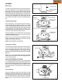
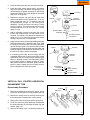
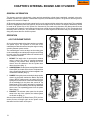
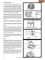
1. Remove the screws holding the diaphragm cover on.
2. Remove the cover, gaskets, and diaphragm noting or
marking the sequence or location to aid in reassembly.
NOTE: If a "F" designation on the choke end of the
carburetor is present, place the diaphragm on first, then
the gasket and cover. If no "F" is present, the gasket
goes first.
3. Note or mark the high and low mixture adjustment
screws. Remove the screw assemblies.
4. Note or mark the action of the choke and throttle
shutters and the hook points of the choke or throttle
return spring or seal retainer springs located on the top
of the choke or throttle shaft. Remove the throttle
shutter, throttle shaft, choke shutter, springs and choke
shaft by removing the screw or screws that attach the
throttle or choke shutter to the shaft inside the air horn.
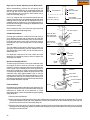
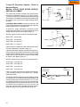
5. Use a 9/32" (7.144 mm) thin wall socket to unscrew
and remove the inlet needle and seat assembly (diag.
36).
6. Note and mark the direction of the inlet fitting. If
necessary the inlet fitting can be removed by pulling
with a pliers or vise. Some diaphragm carburetors have
a strainer as an integral part of the fuel fitting. If the
strainer is lacquered or cannot be cleaned, the fitting
must be replaced.
7. Remove all welch plugs if cleaning the carburetor.
Secure the carburetor in a vise equipped with protective
jaws. Use a small chisel shar pened to a
1/8" (3.175 mm) wide wedge point. Drive the chisel
into the plug to pierce the metal, then push down on
the chisel to pry the plug out of the hole.
NOTE: DO NOT REMOVE ANY BALL OR CUP PLUGS.
"F" DESIGNATION
"F"
DIAPHRAGM FIRST NOT GASKET
36
37
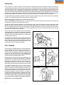
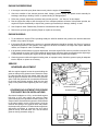
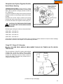
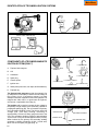
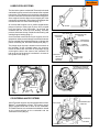
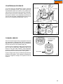
IMPULSE FUEL PUMP
To service, disassemble the pump by removing the four
(4) screws. Clean all parts with a solvent and install a new
kit which consists of a coil spring, gaskets and diaphragms
(diag. 37 & 38).
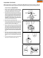
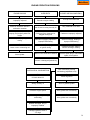
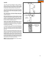
FLOAT ADJUSTING PROCEDURE
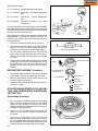
All Tecumseh carburetors with an adjustable float require
the correct float height to achieve the proper operation
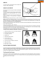
and easy engine starts. To check the float height, hold the
carburetor in an upside down position. Remove the bowl
nut, float bowl, and "O" ring. Place an 11/64" (4.36 mm)
diameter drill bit across the top of the carburetor casting
on the opposite side and parallel to the float hinge pin
(diag. 39). The float must just touch the drill bit when the
bit is flush with the edge of the float. If the float is too high
or too low, adjust the height by bending the tab
accordingly. If the required adjustment is minor, the tab
adjustment may be made without removing the float and
carefully inserting a small bladed screwdriver to bend the
tab.
Float sticking can occur due to deposits or when the fuel
tank is filled for the first time, this condition can be quickly
corrected by loosening the carburetor bowl nut one full
turn. Turn the bowl 1/4 turn in either direction, then return
the bowl to its original position and tighten the bowl nut.
OLD STYLE
NEW STYLE
38
11/64" (4.36 mm)
DRILL BIT
RIM
39
19