1
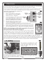
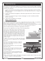
In order to hold the spindle, insert the Tommy Bar into the hole in the side of the head so
that it locates in the hole in the spindle, see Fig. 5. Hold the spindle still whilst nipping up the
draw bolt. .
Fig.6
Place the drill chuck on to the end of the taper shank with
a sharp upward movement.
The drill is lowered using the levers on the right side of the
machine, however, in order to do so, it is first of all
necessary to disconnect the Dog Clutch, shown in Fig. 6.
Simply pull back on the hub to disconnect.
Now by turning the handles, the drill head may be lowered.
In order to ensure the drill chuck is firmly secured on the
spindle, place a piece of wood on the table then lower
the drill head so that the nose of the drill chuck comes
into contact with it. Pull down sharply one time.
When drilling using a mill/drill machine, it must be
remembered that without care, the drill bit could easily
come into contact with the surface of the table.
Drill head travel must always be restricted therefore
before proceeding to drill, otherwise damage to the
table and/or drill bit could occur.
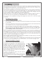
Fig.7
A limiting device is provided, mounted on the post
slide, shown in Fig. 7.
When through drilling, wind the drill head, with drill bit
installed, down to the maximum depth required, and
hold in place whilst sliding the limit device up to meet
it. Lock the limit device in place using its’ locking lever.
The limit device is also used if you wish to drill to a
predetermined depth.
Bring the drill bit down to touch the workpiece surface
and note the reading on the scale on the post.
Move the workpiece away from the drill bit, using the
longitudinal or cross slide handles, then lower the head once again to the depth
previously noted, plus the depth of hole required. At this point, bring the limit device up to
the head and lock firmly in place . Your drill depth is now set.
The workpiece must ALWAYS be firmly secured. This will normally be with the use of a vice
which is securely clamped to the table. Alternatively, clamps may be used. A suitable
vice, and a ‘T’ nut and clamp set designed specifically for this machine, are available
from your Clarke dealer. Please refer to Accessories on page 22.
The table, carrying the workpiece, is manoeuvred using the longitudinal and cross slide
adjusting handles. Once the workpiece is positioned, any further movement is avoided by
locking both longitudinal and cross slides in place using the locking levers provided - see
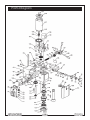
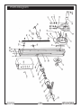
parts identification Fig-B, on page 8.
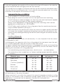
Drill speeds are effected by using either the High or Low ranges together with the variable
speed rotary switch. See notes on cutting speeds on page 13.
WARNING
Never attempt to change ranges until the machine has come to a complete stop
11