1
MODEL 3500
6.5HP Generator
Item # 56350
Owner's Manual
Manual
del Propietario
DO NOT RETURN
TO STORE
Questions? Problems?
Please call our customer help line:
(888) 315-3080
M-F 84 CT
Thank you for purchasing a model 3500 generator. This manual provides information regarding the
operation and maintenance of this product. We have made every effort to ensure the accuracy of
the information in this manual. Wen Products reserves the right to change this product at any time
without prior notice.
Please keep this manual available to all users during the entire life of the generator.
rev. O1/21/05
MODEL 3500
6.5 HP Generator
FEATURES
• 3500 Surge
Watt Output
• 3000 Rated Watt Output
• Powerful Enough to Run Essential
During Power Outages
• 120 and 240 VoltAC
Outputs
• DC Output for Automotive
• Low OilAutomatic
Appliances
Battery Charging
Shutoff
• Circuit Breaker for Overload Protection
• 4 Gallon Fuel Tank Capacity
• Easily Portable-
less than 100 lbs
• Meets EPA and CARB emissions
standards
TABLE
OF CONTENTS
GENERAL SAFETY PROCEDURES ........................................................................
PACKAGE CONTENTS .......................................................................................
GENERATOR
COMPONENTS ..............................................................................
PREPARING THE GENERATOR
FOR USE ...............................................................
Using the Generator for the First Time ...............................................................
Step 1- Add Oil .................................................................................
Step 2- Add Gasoline ..........................................................................
Step 3- Ground the Generator ................................................................
Subsequent Use of the Generator .....................................................................
Step 1- Check the Oil ..........................................................................
Step 2- Check the Gas Level .................................................................
Step 3- Ground the Generator ................................................................
STARTING THE GENERATOR ..............................................................................
USING THE GENERATOR ...................................................................................
AC Usage ................................................................................................
DC Usage ................................................................................................
STOPPING THE GENERATOR ..............................................................................
MAINTENANCE
/ CARE .....................................................................................
Cleaning the Generator .................................................................................
Changing the Oil ........................................................................................
Changing/Adding
Oil ..................................................................................
Air Cleaner Maintenance ..............................................................................
4
8
9
10
10
10
11
11
12
12
13
13
14
15
15
17
18
19
19
19
20
21
Fuel Filter Cup Cleaning ..............................................................................
Spark Plug Maintenance ...............................................................................
Emptying the Gas Tank ................................................................................
STORAGE / TRANSPORT PROCEDURES ...............................................................
SPECIFICATIONS
..............................................................................................
TROUBLESHOOTING
.........................................................................................
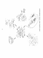
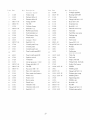
EXPLODED VIEW AND PARTS LIST .....................................................................
WIRING DIAGRAM ...........................................................................................
22
22
23
23
24
25
26
28
Notice Regarding
Emissions
Engines that are certified to comply with California and U.S. EPA emission regulations
for SORE (Small Off Road Equipment), are certified to operate on regular unleaded
gasoline, and may include the following emission control systems: (EM) Engine
Modifications and (TWC) Three-Way Catalyst (if so equipped).
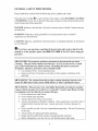
GENERALSAFETYPROCEDURES
Please familiarize
yourself
with the following
safety symbols and words:
The safety alert symbol A is used with one of the safety words (DANGER, CAUTION,
or WARNING)
to alert you to hazards. Please pay attention to these hazard notices both
in this manual and on the generator.
DANGER: Indicates
not followed.
a hazard that will result in serious injury or death if instructions
are
WARNING: Indicates a strong possibility of causing serious injury or death if
instructions are not followed.
CAUTION: Indicates a possibility of personal injury or equipment damage if instructions
are not followed.
{WJ
_
If you have any questions
manual or on the product,
generator.
regarding
the hazard
please call (888)
315-3080
and safety notices listed in this
M-F 8-5CT before using the
A DANGER: This generator produces poisonous carbon monoxide gas when
running.
This gas is both odorless and colorless. Even if you do not see or smell
gas, carbon monoxide may still be present. Breathing this poison can lead to
headaches,
dizziness, drowsiness, and eventually death.
• Use outdoors ONLY in non-confined areas.
•
Keep several feet of clearance
generator.
on all sides to allow proper ventilation
of the
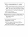
A WARNING: The exhaust from this product contains chemicals known to the
State of California to cause cancer, birth defects, or other reproductive
harm.
A WARNING: This generator may emit highly flammable and explosive gasoline
vapors, which can cause severe burns or even death. A nearby open flame can lead
to explosion even if not directly in contact with gas.
• Do not operate near open flame
• Do not smoke near generator.
• Always operate on a firm, level surface.
• Always turn generator off before refueling. Allow generator to cool for at least 2
minutes before removing fuel cap. Loosen cap slowly to relieve pressure in
tank.
• Do not overfill gas tank. Gas may expand during operation. Do not fill to the top
of the tank.
•
•
•
Always check for spilled gas before operating.
Empty gasoline tank before storing or transporting the generator..
Before transporting, turn fuel valve to off and disconnect spark plug.
WARNING:
electrocution.
•
•
•
•
•
•
This generator
produces
powerful
voltage, which can result
in
ALWAYS ground the generator before using it (see the "Grounding the
Generator" portion of the "PREPARING THE GENERATOR FOR USE"
section).
Generator should only be plugged into electrical devices, either directly or with
an extension cord. NEVER connect to a building electrical system without a
qualified electrician.
Such connections must comply with local electrical laws
and codes. Failure to comply can create a backfeed, which may result in serious
injury or death to utility workers.
Use a ground fault circuit interrupter (GFCI) in highly conductive areas such as
metal decking or steel work. GFCIs are available in-line with some extension
cords.
Do not use in rainy or wet conditions.
Do not touch bare wires or receptacles
Do not allow children or non-qualified
(outlets).
persons to operate.
A WARNING:
This generator produces heat when running.
Temperatures
near
exhaust can exceed 150°F (65 ° C).
• Do not touch hot surfaces. Pay attention to warning labels on the generator
denoting hot parts of the machine.
• Allow generator to cool several minutes after use before touching engine or areas
which heat during use.
CAUTION:
Misuse of this generator can damage it or shorten its life.
• Use generator only for its intended purposes.
• Operate only on dry, level surfaces.
• Allow generator to run for several minutes before connecting electrical devices.
•
Shut off and disconnect any malfunctioning
devices from generator.
• Do not exceed the Wattage capacity of the generator by plugging in more
electrical devices than the unit can handle (see "PRECAUTIONSOVERLOADING
THE GENERATOR").
• Do not turn on electrical devices until after they are connected to the generator.
• Turn off all connected electrical devices before stopping the generator.
In additionto the abovesafetynotices,pleasefamiliarizeyourselfwith the safetyand
hazardmarkingson the generator.
N
PACKAGE
CONTENTS
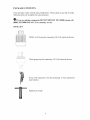
Your generator comes with the items listed below.
following items are included with your generator.
O
If you are missing
(888)
315-3080
ITEM
LIST
components
M-F
DO NOT
8-5 CT for customer
Please check to see that all of the
RETURN
TO STORE,
please
call
service.
NEMA L14-30 plug for connecting
240 Volt electrical
devices
Three-prong plug for connecting 120 Volt electrical devices
i ZZ !i_¸
Set of 2 DC connector
type batteries
Spark plug wrench
wires for connecting
12 Volt automotive-
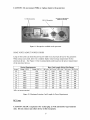
GENERATOR
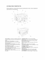
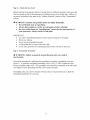
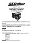
COMPONENTS
Please familiarize yourself with the locations and functions of the various components
and controls of your generator.
10
3
2
5
IG
(1) Air cleaner- a removable, cleanable, sponge-like
element that limits the alnount of dirt pulled into the
engine.
(2) 120 Volt AC Receptacle- Use to connect
electrical devices that run 120 Volt, 60 Hz, single
phase, AC current.
(3) 120/240 Volt AC Receptacle- Use to connect
electrical devices that mn 120 and/or 240 Volt, 60
Hz, single phase, AC current.
(4) 12 Volt DC Receptacle- Use for charging 12
Volt automotive-type batteries only.
(5) Circuit Breaker- Reset switch that protects the
generator from electrical overload.
(6) Choke lever- Adjusts the amount of air let into
the engine.
(7) Engine Switch- Used to start/stop engine.
(8) Fuel Cap- Access to the fuel tank for adding fuel.
(9) Fuel Filter (;up- Traps dirt and water fioln fuel
before it enters the engine.
(10) Fuel Gauge- Indicates the amount of fuel in the
tank.
(11) Fuel valve- Allows fuel to enter engine.
(12) Ground Terminal- Connect grounding wires here
to properly ground unit.
(13) Muffler- Reduces engine noise.
(14) Oil Fill and Dipstick- Location for checking and
filling engine oil.
(15) Recoil Starter- Pull-cord for starting engine.
(16) Spark plug- Provides proper engine ignition.
(17) Volt Meter- Provides reading of voltage output.
PREPARING
THE
Using the Generator
Q
The following
for first-time
GENERATOR
FOR
USE
for the First Time
section describes
steps you must follow
to prepare
your generator
use. If after reading this section, you are unsure about how to perform
any of the steps please call (888) 315-3080
M-F 8-5 CT for customer service.
Failure to perform these steps properly can damage your generator or shorten its life.
If you are using the generator
prepare it for operation:
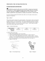
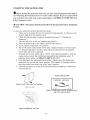
Step 1- Add
for the first time, there are a few steps you must take to
oil
The generator requires engine oil to operate properly. The generator, when new from the
package, contains no oil in the crankcase. You must add the proper amount of oil before
operating the generator for the first time. This amount, which is equal to the oil capacity
of the engine crankcase, can be found on the chart in figure 1. When filling the engine
with oil in the future, please refer to this chart.
Figure
1- Generator
Model
Oil CapaciD
number
Engine
oil
_
2200
3500
5500
20 fluid oz.
20 fluid oz.
37 fluid oz.
capacity
To add
1.
2.
3.
4.
oil, follow these steps:
Make sure the generator is on a level surface.
Unscrew the oil filler/dipstick cap from the engine as shown in figure 2.
Using a funnel, add the appropriate amount ofoil, as found in figure 1, into the
crankcase. You will know the crankcase is full when the oil level has reached the
lower lip of the opening you have just poured the oil into (see figure 3).
Replace oil filler cap.
O_
Ott,
_q_.LER
FLLER
HOLE
CAP
?
Figure
2- Unscrewing the oil cap
Figure 3- Adding oil
10
Step
2- Add
Gasoline
WARNING:
Gasoline
and gas fumes are highly flammable.
•
Do not fill tank near an open flame.
•
Do not overfill. Always check for fuel spills.
To ensure that the generator runs smoothly use only FRESH, U2qLEADED GAS WITH
AN OCTANE RATING OF 87 OR HIGHER. To add gasoline:
1. Make sure the generator is on a level surface.
2. Unscrew gas cap and set aside (NOTE: the gas cap may be tight and hard to
unscrew).
3. Slowly add unleaded gasoline to the fuel tank. Be careful not to overfill. Please
refer to the chart in figure 4 to find the gas capacity of your generator model. The
fuel gauge on the top of the generator indicates how much gasoline is in the
generator gas tank. NOTE: Gas can expand. Do not fill the gas tank to the very
top.
4. Replace fuel cap and wipe up any spilled gasoline with a dry cloth.
IMPORTANT:
•
•
•
•
Never use an oil/gasoline mixture.
Neveruse old gas.
Avoid getting dirt or water in the fuel tank.
Gas can age in the tank and make it hard to start up the generator in the future.
Never store generator for extended periods of time with fuel in the tank.
Figure 4- Gas Tank Capacity
Model number
Gas tank
capacity
2200
3500
5500
15 L (3.96 gallons)
15 L (3.96 gallons)
25 L (6.60 gallons)
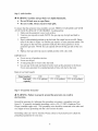
Step 3- Ground the Generator
A WARNING:
electrocution.
Failure to properly
ground the generator
can result in
Ground the generator by tightening the grounding nut against a grounding wire (see
figure 5). A generally acceptable grounding wire is a No. 12 AWG (American Wire
Gauge) stranded copper wire. This grounding wire should be connected at the other end
to a copper or brass grounding rod that is driven into the earth.
Grounding codes can vary by location. Please contact a local electrician
grounding regulations for your area.
11
to check the
j A
i'
Figure
Subsequent
5- Attaching
the Grounding
i!
Wire to the Generator
Use of the Generator
If this is not your first time using the generator
prepare it for operation.
there are still steps you should take to
IMPORTANT:
At this point you should be familiar with the procedures described
in the first portion of this section entitled "Using the Generator for the First Time."
If you have not yet read this section, go back and read it now.
Step 1- Check the Oil
The generator is equipped with an automatic shutoff to protect it from damage due to low
oil. Nonetheless, you should check the oil level of the engine before each use to ensure
that the engine crankcase has a sufficient amount. To check the oil level:
1. Make sure the generator is on a level surface.
2. Unscrew the oil filler/dipstick cap.
3. With a dry cloth, wipe the oil off of the stick on the inside of the cap.
4. Insert the dipstick as if you were replacing the cap and then remove again. There
should now be oil on the stick. If there is no oil on the stick, or oil only at the
very end of the stick, you should add oil until the engine crankcase is filled (see
"Adding Oil" portion of the "Maintenance"
section).
5. Be sure to replace cap when finished checking oil.
NOTE: The oil capacity for your generator
of this manual
can be found in the "Specifications"
12
section
Step
2 - Check
the Gas Level
Before starting the generator, check to see that there is sufficient gasoline in the gas tank.
The fuel gauge on top of the generator will indicate the gas level in the tank. Add gas if
necessary according to the steps in the "Adding Gasoline" portion of the "Maintenance"
section.
A WARNING:
Gasoline
•
Do not fill tank
•
Always
•
Do not overfill
your
allow
and
near
engine
generator).
(check
gasoline
an open
fumes
are highly
flame.
to cool for several
minutes
the "Specifications"
Always
check
flammable.
before
section
refueling.
for the tank capacity
of
for fuel spills.
IMPORTANT:
•
•
•
•
•
Step
Use only U2qLEADED gasoline with an octane rating of 87 or higher.
Do not use old gas.
Never use an oil/gasoline mixture.
Avoid getting dirt or water in the fuel tank.
Never store generator for extended periods of time with fuel in the tank.
3- Ground
A WARNING:
electrocution.
the Generator
Failure
to properly
ground
the generator
can result
in
Ground the generator by tightening the grounding nut against a grounding wire (see
figure 5). A generally acceptable grounding wire is a No. 12 AWG (American Wire
Gauge) stranded copper wire. This grounding wire should be connected at the other end
to a copper or brass grounding rod that is driven into the earth.
Grounding codes can vary by location. Please contact a local electrician
grounding regulations for your area.
13
to check the
STARTING
O
Before
THE GENERATOR
starting
the generator,
sure you
the "Preparing
the Generator
how to perform
any of the steps in this' manual
CT for
customer
for
make
Use" section
have
read andperformed
of this manual.
please
the steps
If you are unsure
315-3080
call (888)
in
about
M-F 8-5
service.
A CAUTION:
to start.
Disconnect
all electrical
loads
from
the generator
before
attempting
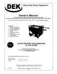
To start your generator, perform the following steps:
1. Make sure no electrical devices are connected to the generator. Such devices can
make it difficult for the engine to start.
2. Check that the generator is properly grounded (see page 13, "Ground the
Generator").
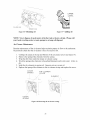
3. Turn the fuel valve to the "on" position (see figure 6).
4. Move the choke lever to the "closed" position (see figure 7).
5. Set the engine switch to the "on" position.
6. Pull on the recoil starter handle slowly until a slight resistance is felt (see figure
8). Then pull quickly to start the engine. Return cord gently into the machine.
Never allow the cord to snap back.
7. If engine fails to start, repeat step 4. NOTE: After repeated attempts to start the
engine, please consult the troubleshooting
guide before attempting again. If
problems persist please call (888) 315-3080 M-F 8-5 CT.
8. Once the engine has started and run for about a minute, move the choke lever
about half way towards the "open" position. Wait another 30 seconds and then
move the choke lever all the way to the "open" position.
9. Allow the generator to run for several minutes before attempting to connect any
electrical devices.
OFF
Models 2200 and 3500
CHOKE
LEVER
ON
Figure 6- Fuel Valve in the "on" position
STARTER
GRiP
CLOSBD
/
ORE[N
//
#
Figure
7- Choke
page
Figure 8- Pulling the start cord
14
in the
9 for
closed
choke
position
location)
refer
to
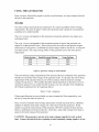
USING THE GENERATOR
Once you have allowed the engine to run for several minutes, you may connect electrical
devices to the generator.
AC Usage
You may connect electrical devices running on AC current according to their wattage
requirements. The chart in figure 9 shows the rated and surge wattage of your generator
according to its model number.
The rated wattage corresponds
continuous basis.
to the maximum
wattage the generator
can output on a
The sul\qe wattage corresponds to the maximum amount of power the generator can
output for a short period of time. Many electrical devices such as refrigerators require
short bursts of extra power, in addition the rated wattage listed by the device, to stop and
start their motors. The surge wattage ability of the generator covers this extra power
requirement.
Model Number
2200
3500
5500
Rated(Running)Wattage
1800
3000
Surge Wattage
2200
3500
5000
5500
Figure 9- generator wattage by model number.
The total running wattage requirement of the electrical devices connected to the generator
should not exceed the rated wattage of the generator itself. To calculate the total wattage
requirement of the electrical devices you wish to connect, find the rated (or running)
wattage of each device. This number should be listed somewhere on the device or in its
instruction manual. If you cannot find this wattage, you may calculate it by multiplying
the Voltage requirement by the Amperage drawn:
Watts = Volts x Amperes
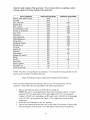
If these specifications are not available you may estimate the Watts required
device by using the chart in figure 10.
by your
Once you have found the rated wattage requirement of each electrical device, add these
numbers to find the total rated wattage you wish to draw from the generator. If this
number exceeds the rated wattage of the generator, DO NOT connect all these devices.
Select a combination of electrical devices, which has a total rated wattage lower than or
equal to the rated wattage of the generator.
CAUTIONThe generator can run at its surge wattage capacity for only a short
time. Connect electrical devices requiring
a rated (running) wattage equal to or less
15
than the rated
wattage
equal
wattage
of the generator.
Never connect
to the surge wattage
of the generator.
tool or appliance
devices
requiring
a rated
rated (running) Watts
additional surge Watts
electric water heater (40 gal)
4000
0
hot plate
saw- radial arm
2500
2000
0
2000
electric stove
saw- circular
1500
1500
0
1500
air compressor (1 HP)
window air conditioner
1500
1200
3000
1800
saw- miter
microwave
1200
1000
1200
0
well water pump
reciprocating saw
sump pump
1000
960
800
1000
1040
1200
refrigerator freezer
furnace blower
800
800
1200
1300
computer
electric drill
television
800
600
500
0
900
0
deep freezer
garage door opener
stereo
box fan
500
480
400
300
500
0
0
600
clock radio
300
0
security system
dvd player/vcr
180
100
0
0
common light bulb
75
0
NOTE: The above wattage figures are estimates.
electrical device before consulting this chart.
Figure
10- Estimated
wattage
requirements
Try to check the wattage listed on your
of common
electrical
Once you have determined what electrical devices you will be powering
generator, connect these devices according to the following procedure:
devices.
with the
1. Plug in each electrical device with the device turned off.
NOTE: Be sure to attach appliances to the correct receptacle (outlet). Connect
standard 120 Volt, single phase, 60 Hz loads only to the 120 Volt receptacle.
Connect 120/240 Volt, single phase, 60Hz loads with a NEMA L14-30 plug only
to the 120/240 Volt receptacle See Figure 11 for a depiction of each of these
receptacles.
2. Switch the circuit breaker to the "on" position.
3. Turn on the connected electrical devices in the order of the amount of power they
require beginning with the device with the highest rated wattage requirement.
16
CAUTION:
Do not connect
Figure
SOME NOTES ABOUT
50Hz
or 3-phase
11- Receptacles
POWER
loads
available
to the generator.
on the generator
CORDS
Long or thin cords can drain the power provided to an electrical device by the generator.
When using such cords, allow for a slightly higher rated wattage requirement by the
electrical device. See Figure 12 for recommended cords based on the power requirement
of the electrical device.
Device Requirements
Watts (120V)
Watts(240
300
600
Amps
2.5
V)
Max. Cord Length (ft) by Wire Gauge
#8 wire #10 wire
#12 wire
#14 wire
#16 wire
NR
1000
600
375
250
5
7.5
600
900
1200
1800
NR
NR
500
350
300
200
200
125
125
100
10
15
1200
1800
2400
3600
NR
NR
250
150
150
100
100
65
50
NR
20
25
2400
3000
4800
6000
175
150
125
100
75
60
50
NR
NR
NR
30
40
3600
4800
7200
9600
125
90
65
NR
NR
NR
NR
NR
NR
NR
*NR= not recommended
Figure
12- Maximum
Extension
Cord
Lengths
by Power
Requirement
DC Usage
CAUTION:
only.
The DC receptacle
Do not connect
any other
is for recharging
device
to this
17
12 Volt
receptacle.
automotive-type
batteries
CAUTION: Use the generator only to recharge
jumpstart a car with your generator.
To connect
12 Volt batteries
12 Volt batteries.
Never try to
to the DC receptacle:
1. Connect one charging wire to the positive terminal on the battery and the other
charging wire to the negative terminal.
2. Connect the free end of the positive wire to the positive receptacle (outlet) on the
generator.
3. Start the generator.
4. Carefully connect the free end of the negative wire to the negative receptacle on
the generator.
5. When disconnecting, always disconnect the wires from the generator first to avoid
a spark.
A DANGER: Storage batteries emit highly explosive hydrogen gas when charged.
Batteries also contain acid, which can cause severe chemical burns.
• Do not allow open flames or cigarettes nearby for several minutes after
charging a battery.
• Always wear protective goggles and rubber gloves when charging a battery.
If battery acid gets on your skin, flush with water.
If battery acid gets in your eyes, flush with water and call a physician
immediately.
If battery acid is swallowed, drink large quantities of milk and call a
physician immediately.
STOPPING
THE GENERATOR
To stop the generator:
1. Turn off, then unplug all connected electrical devices.
2. Switch the circuit breaker to the "off' position.
3. Allow the generator to run for several more minutes with no electrical
connected. This helps stabilize the temperature of the generator.
4. Set the engine switch to the "off' position.
5. Turn the fuel valve to the "off' position.
A WARNING:
Allow the generator
areas that become hot during use.
to cool for several
minutes
before
devices
touching
CAUTION:
Allowing gas to sit in the generator tank for long periods of time
without use can make it difficult to start the generator in the future. Never store
generator for extended periods of time with fuel in the tank.
18
MAINTENANCE/CARE
Proper routine maintenance of your generator will help prolong the life of your machine.
Please perform maintenance checks and operations according the schedule in figure 13.
O If you have questions about any of the maintenance procedures listed in this manual,
please call (888) 315-3080 M-F 8-5CT.
CAUTION:
Never perform
Recommended
maintenance
operations
while the generator
Maintenance Schedule
each use
Engine oil
_heck level
x
Air cleaner
"eplace
sheck
x
every month
or 20 hrs
every 3
months or
50 hrs
every 6
months or
100 hrs
every year
or 300 hrs
x
slean
x
fuel filter cup
slean
spark plu_l
gas tank
sheck/clean
sheck gas level
slean
x
x
x
x
Figure 13- Recommended
Cleaning
is running.
maintenance
schedule
the Generator
Always try to use your generator in a cool dry place. However, in the event your
generator becomes dirty you may clean the exterior with one or more of the following:
a damp cloth
a soft brush
a vacuum
pressurized
air
Never clean your generator with a bucket of water or a hose. Water can get inside the
working parts of the generator and cause a short circuit or corrosion.
Checking
the Oil
The generator is equipped with an automatic shutoff to protect it from running on low oil.
Nonetheless, you should check the oil level of the generator before each use to ensure
that the generator crankcase has a sufficient amount. To check the oil level:
1. Make sure the generator is on a level surface.
2. Unscrew the oil filler/dipstick cap (see figure 14).
3. With a dry cloth, wipe the oil off of the stick on the inside of the cap.
4. Insert the dipstick as if you were replacing the cap and then remove again. There
should now be oil on the stick. If there is no oil on the stick, or oil only at the
19
.
very end of the stick, you should add oil until the engine crankcase
"Changing/Adding
Oil" in this section.
Be sure to replace cap when finished checking oil.
Figure
Changing/Adding
14- Checking
is filled.
See
the oil
Oil
You should check the oil level of your generator according to the maintenance schedule
in figure 13. When the oil level is low you will need to add oil until the level is sufficient
to run the generator.
The oil capacity of your generator engine is listed in figure 15.
Model number
Engine oil
capacity
2200
20 fluid oz.
3500
20 fluid oz.
5500
37 fluid oz.
Figure 15- Engine Oil Capacity.
It is only necessary to drain the oil from the crankcase if it has become contaminated with
water or dirt. In this case, you can drain the oil from the generator according to the
following steps:
1. Place a bucket underneath the generator to catch oil as it drains.
2. Using a 10 mm hex wrench, unscrew the oil drain plug, which is located on the
crankcase underneath the oil filler/dipstick cap (see figure 16). Allow all the oil to
drain from the generator.
3. Replace the oil drain plug and tighten with a 10 mm hex wrench.
To add oil to the crankcase, follow these steps:
1. Make sure the generator is on a level surface.
2. Unscrew the oil filler/dipstick
cap from the engine
3.
as shown in figure 15 above.
Using a funnel, add high detergent motor oil to the crankcase. We recommend
SAE 10W/30 motor oil for general use. When full, the oil level should come close
to the top of the oil fill opening (see figure 17).
2O
DRAIN
PLUG
Figure 16- Draining
oil
Figure 17- Adding
NOTE: Never dispose of used motor oil in the trash or down a drain.
your local recycling center or auto garage to arrange oil disposal.
Air Cleaner
oil
Please call
Maintenance
Routine maintenance of the air cleaner helps maintain proper air flow to the carburetor.
Occasionally check that the air cleaner is free of excessive dirt.
1.
2.
3.
4.
Unhinge the clasps at the top and bottom of the air cleaner cover (see figure 18).
Remove the sponge-like elements from the casing.
Wipe the dirt from inside the empty air cleaner casing
Wash the sponge-like elements in household detergent and warm water. Allow to
dry.
5. Soak the dry elements in engine oil. Squeeze out any excess oil.
6. Replace the sponge-like elements in the air cleaner casing and replace the cover.
COVER
SPR_NG
A_R CLEANER
COVER
ELEMENT
...........
'
"',
gQ*
v
,
g', 77{t_%÷_T<_&
*
_ g*
{,,
i
g
¢*%{
]
f
COVER
SPR_NG
Figure 18- Removing the air cleaner casing.
21
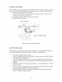
Fuel Filter Cup Cleaning
The fuel filter cup is a small well underneath the fuel valve. It helps to trap dirt and water
that may be in your fuel tank before it can enter the engine. To clean the fuel filter cup:
1. Turn the fuel valve to the "off' position.
2. Unscrew the fuel filter cup from the fuel valve using a wrench. Turn the valve
toward you to unscrew (see figure 19).
3. Clean the cup of all sediment. Using a rag or brush.
4. Reinstall the fuel filter cup.
VALVE
FUEL
FUEL
FILTER
CUP
Figure 19- Removing the Fuel Filter Cup
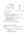
Spark
Plug Maintenance
The spark plug is important for proper engine operation. A good spark plug should be
intact, free of deposits, and properly gapped. To inspect you spark plug:
1. Pull on the spark plug cap to remove it.
2. Unscrew the spark plug from the generator using the spark plug wrench included
with this product (see figure 20).
3. Visually inspect the spark plug. If it is cracked or chipped, discard and replace
with a new spark plug. We recommend using a F6RTC spark plug such as NGK
BPR5ES.
4. Measure the plug gap with a gauge (see figure 21). The gap should be 0.7-0.8mm
(0.028-0.03 lin).
5. If you are re-using the spark plug, use a wire brush to clean any dirt from around
the spark plug base and then re-gap the spark plug..
6. Screw the spark plug back into its place on the generator using the spark plug
wrench. Replace the spark plug cap.
22
PLUG W_ENOH
O, 7@, 8 !_>
_{_
PLUG
z:,
(00260031
n;
CAP
Figure 20- Removing the spark plug
Emptying
Figure 21- Measuring the spark plug gap
the Gas Tank
Before storing your generator for extended periods of time, you should drain your
generator of gasoline. To drain the generator of gas:
1. Turn the fuel valve to the "off' position.
2. Remove the fuel filter cup (see "Removing the Fuel Filter Cup" earlier in this
section.
3. Empty the fuel filter cup of any fuel.
4. With a receptacle underneath the generator to catch the gas, turn the fuel valve to
the "on" position. Drain all the gas from the generator.
5. Turn the fuel valve to the "off' position.
6. Replace the fuel filter cup.
7. Store the emptied gasoline in a suitable place.
A
CAUTION:
STORAGE
A CAUTION:
still hot.
Do not store
/ TRANSPORT
Never
place
fuel from
one season
to another.
PROCEDURES
any type
of storage
cover
on the
generator
while
it is
When transporting or storing your generator for extended periods of time:
• Empty the gas tank (see "Elnptying the Gas Tank" in the "Maintenance"
section).
• Disconnect the spark plug.
• Do not obstruct any ventilation openings.
• Keep the generator in a cool dry area.
23
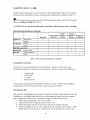
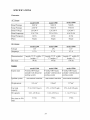
SPECIFICATIONS
Generator
AC Output
model2200
model3500
R_edW_tage
1800W
3000W
5000W
_urgeW_tage
2200W
3500W
5500W
120/240 V
model5500
R_ed Voltage
120/240 V
120/240 V
R_ed Amperage
15 A/7.5A
25 A/12.5A
41A/20.5A
R_ed Frequency
60Hz
60Hz
60Hz
Phase
Single
Single
Single
model 2200
model 3500
model 5500
Voltage
12V
12V
12V
Amperage
8.3 A
8.3 A
8.3 A
length = 23.25 width = 17
height = 17
99 lbs
length = 23.25 width =
17 height = 17
99 lbs
length = 27 width=20
height = 21
168 lbs
model 2200
model 3500
model 5500
DC Output
Dimensions(in):
Dry mass
Engine type
[gnition system
Displacement
Fuel tank
zapacity:
Dil capacity
Run time on 50%
Load
4-stroke OHVsingle
cylinder with forced air
cooling system
non-contact
transistor
4-stroke OHVsingle
4-stroke OHVsingle
=ylinder with forced air cylinder with forced air
=ooling system
cooling system
non-contact
transistor
non-contact
transistor
163 cm 3
196cm 3
337cm 3
15 L (3.96 US gal.)
15 L (3.96 US gal.)
25 L (6.60 US gal.)
0.6 L (20 fl oz.)
0.6 L (20 fl oz.)
1.1 L (37 fl oz.)
21 hrs
15 hrs
15 hrs
24
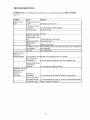
TROUBLESHOOTING
IMPORTANT:
M-F 8-5.
If trouble persists please call our customer
help line at (888) 315-3080
Problem
Cause
Engine will not
start
Engine switch is set
LO"Off".
Set engine switch to "on".
Fuel valve is turned
Lo"closed".
Shoke is open.
Solution
Turn fuel valve to "open" position.
Close the choke
Engine is out of gas. &dd gas.
Engine is filled with
sontaminated or old
gas
Change the gas in the engine.
Spark plug is dirty.
Clean spark plug.
Spark plug is
3roken.
Replace spark plug.
Generator is not on Move generator to a level surface to prevent low oil shutdown
evel surface.
from triggering.
:Dil is low
Add or replace oil.
Engine runs but
there is no
electrical output
Sircuit breaker is off. Set the circuit breaker to the "on" position.
Bad connecting
Mres/cables.
If you are using an extension cord, try a different one.
Bad electrical device
sonnected to
generator.
Try connecting a different device.
Generator runs bul
does not support
all electrical
devices
Generator is
connected.
3verloaded
Try connecting fewer electrical loads to the generator.
Short in one of the
sonnected devices.
Fry disconnecting any faulty or short-circuited
_,ir cleaner is dirty.
Clean or replace air cleaner.
25
electrical loads.
I
b_
fret11
Part
Oty
1
Item
DescriiKion
Part
Gasoline engine
35
31600
36
GB276
Oty
Description
1
Voltage regulator
1
Bearing 6202-2RS
Plain washer
2
41100
1
Frame comp
3
41310
2
Bottom rubber A
37
31134
1
.,I 41320
2
Bottom rubber B
38
31931
8
Flange nut M8
Nut M6
39
31933
,t
1
Flange bolt M6 X 125
Bolt M8X 180
40
31141
1
Generator
89
5
GB6177 86
6
GB802 88
7
41350
t
Cushion, frame
41
31996
8
Bolt M5 X 14
8
GB5787 86
t
Bolt M6X 12
42
30100
1
Stator & rotor Assy
9
41116
1
Rubber pad, frame
43
16610
1
Fuel tank
i0
32520
1
Earth terminal set
44
16500
1
Fuel filler cap comp.
ii
32100
1
Wire harness Assy
45
16521
1
Packing ring
12
32310
1
Switch wire
46
16916
1
Fuel filter
13
35510
1
Consent
47
37820
1
Fuel sensor
i,'I GB5787 86
3
Bolt M4X i0
48
GB819 85
2
Screw M5 X 10
15
37300
1
Control panel Assy
49
GB5787
16
37310
1
Control panel
50
16821
4
4
Flange bolt M6 X 22
Washer
17
37321
1
Control panel case
51
16811
4
Cushion
68511
1
Panel switch mark,RH
16931
1
Outlet pipe
(1,9x d),t. 5x 130
19
68512
1
Panel switch mark,LH
53
16937/168F
2
Tube clip
20
35410
1
Ignition switch
54
16930
1
Fuel cock
21
37420
1
Voltmeter
55
16812
1
Stripe, fuel tank
22
31710
Circuit protector
56
1682,t
,t
Fitting brush, fuel tank
23
GB5787
86
37825
1
Gasket, fuel sensor
2,'I
GB6187
86
2
Flange bolt M6 X 12
Nut M4
57
58
18300/168F
1
Muffler
25
GBS19
2
Pan screw M4 X 10
59
18611
1
Muffler guard
26
32115
1
Boot, AC output wire
60
GB5787
3
Flange bolt M8 X 16
27
32116
1
Boot, main wire harness
61
18110/168F
BV
1
Exhaust pipe comp.
28
31200
1
Stator Assy
62
18221/168F
BV
1
Muffler gasket
29
31936
1
Stator cover
63
18720
1
Supporting plate
3O
31100
1
Rotor comp.
64
18710
1
Muffler stay
31
31370
1
Brush Assy
65
GB5787
86
2
Bolt M8 X 25
32
31411
1
Generator
stay
66
GB6187
86
2
Nut M8
33
31938
1
Generator
end cover
67
GB5787
86
6
Flange bolt M6 X 12
3d
31995
3
Bolt M5 X 12
68
12255/168F
1
Exhaust pipe gasket
18
1
85
(30A)
52
(10A)
27
86
BV
86
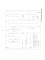
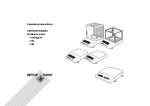
t:an
CONTROL
PANEL
BLOCK
BREAKER
Br
(_
13
q-,
Br
Main col! 1
AC 120V,2_0V
13
R
©
L
_ain coi! 2
vO
Bu
ENGSWITEH
BL
_'
I_
AVR
Excitatio_ coil
ENGINE
BLOCK
ENGSWITEH
Field col
KG
E
OFF (_ @
FUSE
ON
R
BCcoil
BL Black
R
red
Y
W
write
Br
Brown
YiO
yellow
BU blue
6
GENERtTOR
BLOCK
Spark piub
Ignition coil
Fuel level switch
green
NOTES:
29