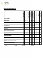
1
Installation and maintenance manual
Closed circuit evaporative cooler
Axial type
Series RAA
W-Tech S.r.l.
Via Moglio, 18/2 - 40037 Sasso Marconi - (BO) Italy
T: +39 051 6783010 F: +39 051 6784941
[email protected] - www.w-tech.it
Reg. Imp. BO C/F - P.Iva: 03079111203 - Rea BO 490312 - Cap. Soc. 32.000 € i.v.
TABLE OF CONTENTS 1. MACHINERY DESCRIPTION 1.1 General safety use 1.2 General description 1.3 Primary Circuit. 1.4 Secondary Circuit 1.4.1 Water pumping system 1.4.2 Water distribution system 1.5 Air induction system 1.6 Casing and water collection basin. 2 2. DELIVERY AND HANDLING Delivery Method 2.1 2.1.1 Lower body 2.1.2 Middle body (if any) 2.1.3 Upper body 2.2 Handling 4 4 4 4 4 4 3. INSTALLATION 3.1 Tower foundation and anchoring 3.2 Location conditions 3.3 Assembly of the bodies 3.4 Electrical connection 3.5 Other details for the installation 5 5 6 7 7 7 2 2 2 2 2 2 3 4. OPERATIONS TO BE CARRIED OUT BEFORE THE START UP 4.1 Cleaning 4.2 Inspection and checking 8 8 8 5. START UP 5.1 Secondary circuit 5.2 Primary circuit 8 8 8 6. OPERATING INSTRUCTIONS 6.1 Tower Performance 6.2 Control of water quality in the circuit 6.2.1 Fouling and blocking 6.2.1.1 Salt precipitation 6.2.1.2 Suspended solids 6.2.1.3 Biological growth 6.2.2 Corrosion 6.3 Electrical locking 6.4 Cold weather operation 8 8 8 8 8 8 9 9 9 9 7. GENERAL MAINTENANCE INSTRUCTIONS 7.1 In the water pumping system 7.1.1 Grid 7.1.2 Basin 7.1.3 Water make‐up 7.1.4 Electric pump 7.1.5 Water distribution system 7.1.6 Coil 7.2 In the air induction system 7.2.1 Motors 7.2.2 Fans 7.3 Casing and water collection basin maintenance 7.4 Drift eliminator 10 10 10 10 10 10 10 11 11 11 11 11 11 8. PREVENTIVE MAINTENANCE SUMMARY CHART 12 9. TROUBLESHOOTING 13 10. RECOMMENDED WATER CHARACHTERISTIC 14 Pag 1 1. GENERAL SAFETY RULES AND MACHINERY DESCRIPTION 1.1
General Safety use: The content of this manual is to be considered as an integration to the general safety rules applied in your country, in the environment you are working in and also to the rules to be followed by law. In case of conflict with any of the previously mentioned rules in place, please contact our technical office for alternative procedures that will not create conflict. Always remember that any operation with mechanical machinery could be dangerous and make sure all possible precautions are followed before and during assembly & maintenance. SAFETY FIRST ! 1.2 General description Closed circuit cooling towers of the RAA series are counter‐flow induced draught coolers with the fluid to be cooled (primary circuit) circulating in a closed sealed loop. The fluid to be cooled pass through a coil, externally sprayed continuously with water, pumped in an open circuit (secondary circuit) from the collection water basin. The evaporation of part of this water removes most of the heat from the fluid in the primary circuit. Evaporation is achieved thanks to a high quantity of air moved, by the use of axial fan(s) installed on top of the unit, counter‐flow against the water of the secondary circuit. The closed circuit cooling tower is composed by the following elements: Primary circuit: • Coil Secondary circuit: • Water pumping system • Water distribution system 1.3 Other: • Air system • Casing, water collection basin, air intake and louver panels. • Drift eliminator Primary circuit (coil) Coil is made by high quality carbon steel bended and welded. A further process of hot dip galvanization assures the necessary protection against external corrosion. Coil can be supplied on request in stainless steel both 304 and 316 grade. During assembly the coil is tested in accordance to actual rules (PED). A further test is done before fitting the coil into the machine. Different test procedures or witnessed tests are possible with extra costs. 1.4 Secondary circuit 1.4.1 Water pumping system The exchange coil is sprayed with water collected from the basin of the unit and pumped by the use a centrifugal pump inside a water distribution system. The motor of the pump is directly coupled on the bronze impeller and installed in a vertical position facilitating inspection and maintenance. The water is then collected in the basin of the unit and ready to be pumped again, after passing through a stainless steel filter/strainer installed in the bottom of the basin. 1.4.2 1.5 Water distribution system Water is pumped in the top of the closed circuit cooler and distributed through a galvanised steel collector and polypropylene (PP) pipe network. It could also be supplied in Stainless Steel with extra cost. Spray nozzles (made by static fibreglass reinforced polypropylene) are screwed into the PP pipes and allow water to drop onto the coil. Nozzles have a wide water passage, with minimum possibilities of clogging, breaking down or blocking. The design of the nozzles is studied to allow the perfect water distribution (full cone) over the coil. In case of clogging or breaking or just for simple maintenance, they can be dissembled from the PP pipes and easy cleaned or replaced. Make‐up water, to replace depletion through evaporation or elimination to avoid scaling, is carried out automatically by means of an intake valve installed in the basin. Air system Air is supplied in counter‐flow to the water and is provided by axial fan(s) statically and dynamically balanced, installed at the top of the cooling tower (induced draught). The fan can be manufactured in different materials (PP, Aluminium, etc.) being placed inside the diffusers, which can also be manufactured in different materials like painted galvanised steel (standard) or stainless steel. An arrow indicates the fan direction to be used. In order to protect the fan from any external object and to prevent injuries a stainless steel safe‐guard grid is installed in the upper part of the diffuser. The electric motor(s), totally sealed and self‐ventilated, are provided standard with class F insulation, capable of withstanding a temperature of 155°C. Electric motors are in accordance to the EU 690/2009 norm (if applicable). Running speed can vary in accordance to each single machine project specification. Special motors can be fitted on demand. Motor(s) are mounted on a galvanized steel support or plate, and installed inside the cooling tower, just below the fan. In order to eliminate frictions, wearing or unnecessary maintenance (typical of an indirect coupling) the coupling between electric motor(s) and fan(s) is direct. Between the coil(s) and fan(s), a layer of drift eliminator made by PVC is provided. Pag 2 1.6 Casing and water collection basin 2
The body of the unit is manufactured in “Sendzimir” galvanised steel covered with 300 g/m zinc layer. As a standard, a minimum 70µ complete paint of epoxy‐polyester layer is applied on each side of the panels. The application is done by electrostatic process, completed by a further one hour stop in to the oven. This is giving a considerable resistance against water corrosion, ultraviolet rays and other atmospheric elements. This painting procedure is internally named W‐COAT® and is given as standard protection on all products manufactured W‐Tech. The lower body of the casing forms the cold water basin. A minimum 2% slope is granted, in order to naturally flow water out of it. On one side of the basin, a stainless steel anti cavitations suction filter is provided to protect the re‐circulating pump that is installed outside the basin. In the water basin, the following standard connections are provided: • Make up water with float valve • Overflow • Drainage Other connections could be provided in accordance to the additional option element are possible to fit. For a quick review and not limited to, we can mention: • Electric heater (to avoid water freezing in the basin in winter time) • Minimum water level switch for heaters (to protect electric heater to work uncovered by water) • Minimum water level switch for pump (to protect re‐circulating pump to work without the necessary water level) Full list of options are listed in the technical sheet. Pag 3 2. DELIVERY AND HANDLING 2.1 Delivery method All models of this series are delivered with the maximum possible elements mounted in our factory. Depending on the height of parts, the unit will be divided in order to lower the transport costs. Generally the deliveries are carried out in two or more parts. To facilitate the handling operation, the single parts are laid on a wooden pallet. Connection elements to be used on site (gaskets, silicone, nuts and bolts) are supplied in a separate box. 2.1.1 Lower body This is composed of the following elements: • Cold water basin with all its elements • Secondary circuit centrifugal pump (delivered loose in case motor power is over 5.5 kW) • Secondary circuit external pipe (lower part – delivered loose) • Air intake section • Coil primary circuit (if not delivered separated) 2.1.2 Middle body (if any) This is composed of the following elements: • Coil primary circuit (if not delivered together with the lower body) 2.1.3 Upper Body This is composed of the following elements: • Air system (Fan(s), Motor(s)) • Diffuser and fan‐guard • Water distribution system, secondary circuit • External secondary circuit pipe (upper part – delivered loose) • Drift eliminator WOOD SUPPORTS AS WELL AS THE PLASTIC OR CARBOARD SHEETS HAVE TO BE REMOVED BEFORE INSTALLING THE COOLING TOWER IN ITS FINAL LOCATION. PARTICULAR ATTENTION HAVE TO BE GIVEN TO CHECK WATER BASIN, WATER PIPES AND WATER DISTRIBUTION SYSTEM TO BE FREE OF ANY PARTS WHICH CAN CAUSE PROBLEMS OR DAMAGES TO THE NORMAL FUNCTION OF THE COOLING TOWER. ALL AUXILIARY MATERIAL NEEDED FOR ASSEMBLY ARE DELIVERED IN A BOX, INSIDE THE LOWER BODY. 2.2 Handling To facilitate the handling of each single part, eyebolts are fitted, located at the top, so that lifting and handling, by crane, can be carried out easily. This can be observed in figures 1 & 2. THE EYEBOLTS ARE ONLY FOR USE IN TRANSPORTING AND HANDLING THE BODY THAT THEY ARE ATTACHED TO. ALL EYEBOLTS MUST BE USED IN THESE OPERATIONS. THEY MUST NEVER BE USED FOR MOVING THE TOWER ONCE IT HAS BEEN ERECTED AND BOTH BODIES ARE ASSEMBLED. The lower body handling will be carried out using all its eyebolts due to its weight, as indicated in fig. 1. To move the upper body, all eyebolts will be used as well, as indicated in fig. 2 Fig. 1 Fig. 2 Pag 4 3. INSTALLATION 3.1 Tower foundation and anchoring Our units have no needs of any special foundation. They can be placed directly onto a concrete slab or onto concrete coated ground, making sure in all cases that the anchoring is capable of resisting the operating load distributed by the tower bed‐frame. They can be anchored on two steel beams, all along the basin. This anchoring can be observed in fig. 3 and will need some bolts and nuts to be fitted. In any case, the surface has to be perfectly level before installing the tower. The tower must not be levelled using wedges or any other element between the beams and the basin, because it will not give adequate longitudinal support. 3.2 Location conditions The tower must never be located in an area that is enclosed on all four sides. Sufficient clearance must be provided all around the tower, so that the cold air may circulate at a speed lower than that of the hot air outlet stream. Therefore, this passage section must be equal in size or bigger than the base plan section of the tower. Any obstacle above the tower at a height lower than that of the tallest side of the tower shall be avoided. Sufficient space must be provided around the tower to allow access to all parts requiring maintenance. See fig 4. Fig. 3 Fig. 4 Pag 5 3.3 Assembly of the bodies Before beginning the assembly on site, check that all elements delivered inside the basin have been removed. To access the basin, the bolts used to capture the angle that is used to hold the louvers panels have to be eased. Then the angle is to be removed, as well as some panels. The angle to be removed is located in the adjacent side where the floating valve is placed. See fig. 6a e 6b. Fig. 6a ‐6b Once the lower body has been installed, the entire perimeter of the assembly flanges must be cleaned. Then, a rubber sealing gasket (supplied) will be installed in order to avoid any damp and/or dirt, just in the centre line of the holes of the flange. If the cooling tower has a flange without holes, then a double line of superimposed gaskets will be installed, as shown in fig. 7, in order to protect these bodies more thoroughly. Once the gasket has been installed, it is recommended to introduce a pointer in the holes, in order to remove any traces of the gaskets that might be left there. WHEN ASSEMBLING BOTH BODIES, CHECK THAT BOTH PARTS OF THE EXTERNAL PIPE ARE PLACED ON THE SAME SIDE, IN ORDER TO FACILITATE THE INSTALLATION. Pag 6 The assembly could he helped by means of pointers, which will be inserted in the holes in the lower body just before the upper one is allowed to rest on it. Please see fig. 7. 3.4 Fig. 7 Electrical connection Our units are normally supplied with the electrical motors already cabled and the wires are available outside of the unit minimizing the labour on site. In case of particular motor versions or if the electrician is willing to re‐wire all, please find below the procedure to follow. In order to connect the motor of the fans, it is necessary to go inside the upper body, through its inspection manholes, see fig. 2. Introduce the connection cable till the terminal box, through the holes available in the casing. Capture the cable to one of the pipes that composes the motor support, by means of clamps. See fig. 8. Fig. 8 To make the connection of the motors (and also of the fans and the electrical pump) the following measures have to be considered: • Before connecting the motor terminals to the mains, make sure that the terminal voltage shown on the motor plate is the same as the mains voltage. • Make sure that motor terminals are tightened securely and that all stripped wires are carefully insulated in order to carry out the connection. • Check that the rotation direction of the fan is the same as the direction of the arrows available on the diffuser. • We recommend that the mains supply line to the motor should be protected with well calibrated thermal relays and fuses. Please remember that in across‐the‐line starting, a squirrel cage motor needs an intensity 6 to 7 times higher than the nominal one. • Make sure the local electrical safety regulations in force have been respected. 3.5 Other details for the installation • Check and remove any material or element which has been part of the packing, and could be still joined to or inside the tower. • Connect both external parts of the pipe. Pag 7 4. OPERATIONS TO BE CARRIED OUT BEFORE THE START UP 4.1 Cleaning • Make sure that the distribution system is clean and that the distribution nozzles are correctly positioned and free of any kind of blockage. • Check if the water basin is completely clean, if not, clean it using water under pressure. 4.2 Inspection and checking • Check the anchoring of the tower, the fans and motors and make sure they are correctly and securely tightened. • Inspect the motors by sight, checking that they have been correctly installed. • Check the connections of the terminal boxes of the motors. • Make the fan turn for an instant, making sure that it turns easily and in the correct direction, without any unusual noise or friction. 5. START UP 5.1 Secondary circuit 1. Fill the cold water basin through the make‐up water pipe or, better still, by means of flexible hose inserted provisionally into the basin. 2. Adjust the float arm of the make‐up valve to ensure the level is maintained around 25 mm below the overflow level. 3. Switch on the electric pump, checking its consumption. NEVER RUN THE PUMP WITHOUT WATER IN THE BASIN !!! 4. The level of water inside the basin, with the electric pump working, has to be always above the suction level of the electric pump and grid, in order to avoid cavitations. This level can be checked from the manhole door, with the electric pump working and the fan(s) completely stopped. 5. Once this regulation has been achieved, the fan(s) motor can begin to work and the cooling tower is prepared to start up. 5.2 Primary circuit Once the operations of starting up on the secondary circuit have been performed, the primary circuit pump will be switched on, checking its consumption. VERY IMPORTANT !! THE TOWER MUST NEVER OPERATE WITHOUT HAVING THE FANGUARD AND THE ACCESS DOOR CORRECTLY FITTED. THE FAN MUST BE STOPPED BEFORE THE OPERATIONS OF REMOVING AND REPLACING THESE ELEMENTS ARE CARRIED OUT. 6. OPERATING INSTRUCTIONS 6.1 Tower Performance In order to obtain the appropriate performance from the cooling tower, care must be taken that the flow of both fluids are the design ones, the secondary circuit water distribution is correct, and the different items in the distribution system must are clean and clear. If a change in the secondary circuit water flow is required, it might be necessary to replace the nozzles, depending on the difference between the design flow and the new required flow. Please consult W‐TECH. It is essential to keep the coil clean, as otherwise the cooling tower performance will be reduced. It is advisable to visually inspect the coil periodically. In the same way, it must be considered that the tower does not govern heat load and, therefore, the fact that the thermal range (difference between fluid in the primary circuit inlet and outlet temperature) is higher or lower than the design data, is irrelevant. 6.2 Control of water quality in the circuits Controlling the quality of the recirculating fluids is essential, not only for the cooling tower it self but also for all the elements that make up the cooling circuits. We recommend that companies specialised in fluid conditioning and treatment should be consulted about the fluids for each circuit. However, some general rules and instructions to be followed for correct circuit control are given below: This control must be aimed at preventing the elements in the circuits from: 1. Fouling and blocking. 2. Corrosion. 6.2.1 Fouling and blocking This is caused by: 6.2.1.1 Salt precipitation (scaling), by their solubility product being exceeded. The most common salts are: • Calcium Carbonate. • Calcium Sulphate. • Silicates. Pag 8 The following conditions must be maintained in order to eliminate them: • Ryznar index = 2 pHs ‐ pHc between 6 and 7. Where pHs is the pH of saturation and pHc is the true level measured in the circuit. • The product of sulphates and calcium concentration in the circuit water, (both expressed in mg/l Co3 Ca), should be less than 500,000. • Silica content should be lower than 150 mg/l. 6.2.2 6.2.1.2 Suspended solids. These can be brought into the secondary circuit of the cooling tower by the make‐up water, by the air or by contamination during the process. In the secondary circuit of the cooling towers, 100 to 150 p.p.m. of suspended solids can be admitted. 6.2.1.3 Biological growth The ambient conditions existing in a cooling tower favour biological growth. It is usually necessary to periodically treat circuits with chlorine and/or other biocides in order to prevent these growths. Treatment of this kind is particularly necessary when the circuit might suffer casual (accidental) pollution caused by process fluids, as happens in refineries, sugar refineries, etc.. Corrosion Besides keeping the Ryznar index in the stable or slightly corrosive zone, corrosion inhibitors must be added to the secondary circuit. Several varieties are commercially available and the most suitable should be selected in consultation with specialized firms. The above leads to a limitation on the maximum number of concentrations acceptable in the secondary circuit. The number of concentrations is called "Concentration Cycles" and is represented by the letter N. If we call: E: Evaporated water flow in the tower as a percentage of nominal water flow. P: Total blow down (drift in tower plus losses in circuit plus deconcentration blow down) as a percentage of nominal water flow. The following ratios are obtained: Average make‐up water flow as a percentage of circulating water flow: 1
Total blow down needed in the circuit as a percentage of circulating water flow: 6.3 1
Which are used to control the number of concentrations, usually determined by dividing the concentration of chlorides in the circuit by the chlorides in the make‐up water. N values (Concentration Cycles) higher than 5 (five) are not usually practical, even when the make‐up water quality is good. ALWAYS MAKE SURE THAT ANY PRODUCT USED FOR WATER TREATMENT AND CLEANING IS COMPATIBLE, AND IN THE PROPER CONCENTRATION, WITH THE MATERIALS OF THE UNIT (GALVANISED STEEL, PP, STAINLESS STEEL, ETC) AND WILL NOT DAMAGE THE COMPONENTS OF THE UNIT IT SELF Electrical locking To ensure this, we recommend that a key‐operated stop switch should be fitted, making it impossible to operate when the key is not in the lock. VERY IMPORTANT! BEFORE REMOVING THE FANGUARD OR THE ACCESS DOOR TO THE MECHANICAL EQUIPMENT, IN ORDER TO CARRY OUT MAINTENANCE OPERATIONS, ALWAYS MAKE ABSOLUTELY SURE THAT THE FAN IS STOPPED AND THAT IT CAN NOT BE RESTARTED UNTIL THESE OPERATIONS HAVE FINISHED. 6.4 Cold weather operation Cooling tower operation at temperatures below 0°C might give rise to the formation of layers of ice at the air intakes. Ice formation can be reduced, and even prevented, by taking the following measures: • Install heating resistances and a level sensor • Add an antifreeze solution in the primary circuit Pag 9 7. GENERAL MAINTENANCE INSTRUCTIONS Due to the quality of these units, maintenance requirements are minimal. Nevertheless, they will be inspected fully on a monthly basis. In the same way, the entire circuit should be cleaned every year. It is advisable to carry out certain actions regularly in order to ensure that you achieve the service life and performance that these units have been designed for There are two basic areas to cover: 1. 2. Water recirculation system Air blowing system 7.1 In the water recirculation system Due to the fact that the systems in which these products are based are related to evaporation, some salty concentrations, as well as suspended solids are produced. Therefore, some secondary water flow has to be removed, in order to prevent the concentrations in the coils. The drainage connection will be used to do this. The water conditions will be controlled continuously and automatically, by purging of dirty water and replacement with clean, addition of bio dispersant agents and biocides, inhibitors to prevent lime scale from building up or the corrosion of the metallic parts of the circuit. Several varieties are commercially available and the most suitable should be selected in consultation with specialised firms, who have the knowledge of the water in the installations and the area. Be careful if any acid product is being used, due to the fact that is not recommended the PH to be lower than 6.5. Another aspect to take into consideration is the fact that the products being used have to be compatible with the kind of materials composing the cooling towers. These units will be disinfected twice a year, at the beginning of spring and of autumn, as well as in the following circumstances: • Before putting into operation. • If they have been stopped for a long period of time. • When repairs have been carried out. • When routine inspection so indicates. • When the Sanitary Authorities so determines. Disinfection will be carried out using authorised disinfectants; if chlorine is used, inject 5 p.p.m. of chlorine plus bio dispersants into the basin and set the pumps running for five hours. The fans will be stopped. Following this, all the water will be drained from the circuit and it will be cleaned thoroughly, adding water until the drain water appears clean. Finally, it will be filled with clean water and between 5 and 15 p.p.m. of chlorine will be added. The pumps will be allowed to run for 5 hours, with the fans stopped (check the chlorine level every hour). The water conditions will be controlled continuously and automatically, by purging of dirty water and replacement with clean, addition of bio dispersant agents and biocides, inhibitors to prevent lime scale from building up or the corrosion of the metallic parts of the circuit. The water will be drained out of the basin when the unit is not in use. The maintenance functions to be carried out for the different elements are listed below. 7.1.1 7.1.2 7.1.3 7.1.4 Grid This has to be cleaned monthly, or as frequently as the sediment presence requires. Basin This has to be cleaned and drained monthly, or as frequently as the sediment presence requires. Water make‐up Float valve will be check monthly, as well as the water level in the basin, it always has to work above the grid and suction level of the electric pump. Electric pump No special maintenance is needed. After around 10,000 working hours, bearings have to be checked, as well as the mechanical locking. If the tower is being stopped for a while, the removal of all water inside the pump is recommended, by means of the drainage connection at the bottom. VERY IMPORTANT !! WHEN RUNNING THE PUMP AFTER BEING STOPPED, ALWAYS TAKE INTO CONSIDERATION THAT THE PUMP MUST BE CHARGED. 7.1.5 Water distribution system This has to be checked monthly. To do so, some eliminator blocks have to be removed in order to inspect the inside part. The fans have to be stopped and the electric pump will be switched on. The nozzles, which are wide passage, with minimum possibilities of breaking down or blocking, allowing perfect water distribution (full cone) over the coil. If by any chance they become clogged, they can be dissembled very easily. This will mean that the grid is not clean, or the distribution pipes are dirty. Therefore, the grid will be cleaned, the nozzles will be removed if necessary to do so, and the pump will be switched on, in order to clean the pipes. If the nozzles have to be removed, when reinstalling in their place, be careful to put them in the correct position, as shown in fig. 10. Pag 10 7.2 7.1.6 Coil The coil has to be observed regularly. It has to be considered that this is a key element in the performance of the tower. Therefore, due to the possibilities of scaling, a monthly check is recommended and a daily purge of part of the spraying water. Fig. 10 In the air flow system The airflow system does not require any special attention, due to its strength. Nevertheless, like any other moving element it has to be regularly checked, following the instructions below. 7.2.1 Motors Motor maintenance is essentially limited to keeping winding and cooling ducts clean, as well as attending bearings. If the motor has grease‐lubricated bearings, also perform this lubrication. The casing temperature that can reached approximately to 90 or 100°C, a temperature that the hand cannot resist might lead one to think that the motor is not operating correctly. It is not necessary, as was the custom in the past, to take the casing temperature as the only indicator to determine correct motor operation. 7.2.2 7.3 7.4 Fans A monthly inspection has to be carried out, in order to remove any paper, leaves or any other elements which could enter the impellers. Casing and water collection basin maintenance The tower has to be checked and cleaned twice at year at least. The basin needs cleaning periodically, since otherwise the drain outlets, overflows, valves and circulation pumps would become blocked. We recommend draining and cleaning each month, or as often as necessary, in accordance with the legislation in force, so as to prevent the build‐up of sediment. At least twice a year the casing will be checked, as well as cleaning the tower external and internally. If any corrosion is appreciated, proceed in the following way : 1 Clean the affected zone by means of a steel brush. 2 A zinc layer has to be applied 3 Apply an Aluminium layer over the zinc layer. Drift eliminator A general cleaning should be carried out twice a year at least, proceeding to its substitution if necessary. Pag 11 M
M
M
CLEANING AND DISINFECTION
M
M/N
M/N
S/N
S
M
S
N
S
S
M
BASIN WATER LEVEL
M
INSPECTION FOR OVERHEATING, NOISE AND VIBRATION
S/N
INSPECTION FOR LEAKS
M
S/N
S/N
N
TIGHTENING OF BOLTS AND ANCHORING
N
BALANCING AND ALIGNMENT
N
LUBRICATION (please check also the instruction manual of the suppliers)
BLOWDOWN FLOW AND CONCENTRATION CYCLE CHECKING
D = Every Day
COLD WEATHER
OPERATION
M
INSPECTION OF THE GENERAL CONDITION
CASING
M/N
M
INSPECTION FOR FOULING
FAN
DRIFT ELIMINATOR
M
OPERATIONS TO BE CARRIED OUT
MOTOR
WATER
DISTRIBUTION
M
ELECTRIC PUMP
WATER MAKE-UP
BASIN
GRID
BLOWDOWN
8.- PREVENTIVE MAINTENANCE SUMMARY CHART
M= Every Month
N
D
S = Every six Months
N = When Needed
9.
TROUBLESHOOTING CHART
DEFECT
POSSIBLE CAUSE
ACTION TO BE TAKEN
MOTOR ROTATES IN OPPOSITE DIRECTION
Error in connection.
Change two phases in the power supply to the motor.
ABNORMAL VIBRATION IN MECHANICAL
EQUIPMENT
Fan / fan motor.
Check state of blades and that they are correctly secured. Clean deposits from blades,
eventually verify ice formation in winter.
Check motor bolts and eventually tight.
BAD HOT WATER DISTRIBUTION
BAD THERMAL EFFICIENCY OF THE TOWER
Nozzles are blocked, broken or lost.
Drift eliminator is blocked.
Incorrect water distribution.
Fouling coil.
Air intake grids are obstructed.
Basin water filter
Remove the nozzles and clean them. Eventually replace it.
Remove the drift eliminator, clean and eventually replace it.
Remove the nozzles and clean them. Eventually replace it.
Check recirculation pump (wiring, rotation, flow)
Contact water treatment specialist for an appropriate clean.
Clean. Eventually replace.
Inspect and clean.
THE MOTOR DOES NOT START, STARTS WITH
DIFFICULTY OR DOES NOT REACH ITS RATED
SPEED AND OVERHEATS.
Bad switch connection.
Interruption in connection or in winding.
Short circuit in the field winding.
The rotor or the fan is jamming.
Short circuit to the casing or to earth.
Excessive number of motor starts.
Connect the motor correctly.
Find and eliminate the interruption.
Find and eliminate the short circuit in the windings (rewind the motor).
Find and eliminate the mechanical defects.
Find and eliminate the short circuit between the turns or the short circuit to the casing.
Extend the duration of stops in motor operation or reduce the number of starts.
ASYMMETRY OF THE CURRENT STRENGTH IN
THE SUPPLY WIRES
Interruption in connection or in winding.
Short circuit in the field winding.
Short circuit to the casing or to earth.
Find and eliminate the interruption.
Find and eliminate the short circuit in the windings (rewind the motor).
Find and eliminate the short circuit between the turns or the short circuit to the casing.
LACK OF CURRENT IN ONE OF THE WIRES
Interruption in connection or in winding.
Find and eliminate the interruption.
TEMPERATURE RELAY CUTS OFF CURRENT
WHEN MOTOR IS CONNECTED OR DURING
OPERATION
Excessive number of motor starts.
Bad switch connection.
Interruption in connection or in winding.
Short circuit to the casing or to earth.
Temperature relay is incorrectly adjusted.
Motor prepared for triangle connection and star connected.
Extend the duration of stops in motor operation or reduce the number of starts
Connect the motor correctly.
Find and eliminate the interruption.
Find and eliminate the short circuit between the turns or the short circuit to the casing.
Correctly adjust the temperature overload relay.
Connect the motor correctly.
THE MOTOR RATTLES
Interruption in connection or in winding.
Short circuit in the field winding.
Short circuit to the casing or to earth.
Find and eliminate the interruption.
Find and eliminate the short circuit in the windings (rewind the motor).
Find and eliminate the short circuit between the turns or the short circuit to the casing.
PUMP MAKES NOISE
Particles or elements inside pipes.
The pump and/or pipe are not well assembled/fixed.
Inspect basin, filter and pipes. Clean and remove.
Fix the pipes and/or electric pump correctly.
Pag 1
Caratteristiche raccomandate acqua
Recommended water charachteristic
Caractéristiques de l’eau recommandées
Minimale Wassereigenschaften
Рекомендуемые характеристики воды
Proprietà
Property
Propriété
Eigenschaft
Свойство
Z-275
Galvanized steel
Tôle en acier zingué
Verzinkter Stahl
Оцинкованная сталь
AISI 304
Stainless Steel
Acier Inoxydable
Edelstahl
Нержавеющая сталь
AISI 316
Stainless steel
Acier Inoxydable
Edelstahl
Нержавеющая сталь
pH
Solidi totali in sospensione (ppm)
Total suspended solids (ppm)
Solides totales en suspension (ppm)
Suspendierter Festanteil, Gesamt (ppm)
Общее содержание взвешенных
веществ (ppm)
Conduttività (micro-Siemens/cm)
Conducivity (micro-Siemens/cm)
Conductivité (micro-Siemens/cm)
Leitfähigkeit (micro-Siemens/cm)
Электропроводность (микро Сименс/см)
Alcalinità CaCO3 (ppm)
Alcalinity CaCO3 (ppm)
Alcalinité CaCO3 (ppm)
Alkalinität CaCO3 (ppm)
Щёлочность CaCO3 (ppm)
Durezza CaCO3 (ppm)
Hardness CaCO3 (ppm)
Dureté CaCO3 (ppm)
Härte CaCO3 (ppm)
Плотность CaCO3 (ppm)
Silice SiO2 (ppm)
Silica SiO2 (ppm)
Silice SiO2 (ppm)
Silizium SiO2 (ppm)
Диоксид кремния SiO2 (ppm)
Cloruri Cl- (ppm)
Clorides Cl- (ppm)
Chlorures Cl- (ppm)
Chloride Cl- (ppm)
Хлориды Cl- (ppm)
Carica Batterica totale (cfu/ml)
Bacterial (cfu/ml)
Charge totale bactérienne (cfu/ml)
Keimbelastung, Gesamt (cfu/ml)
Содержание бактерий (кое/мл)
Solfati SO4 2- (ppm)
Sulphates SO4 2- (ppm)
Solfates SO4 2- (ppm)
Sulphite SO4 2- (ppm)
Сульфаты SO4 2- (ppm)
7,0 – 9
6,0 – 9,5
6,0 – 9,5
< 25
< 25
< 25
< 2.400
< 4.000
< 5.000
75 – 600
< 600
< 600
50 – 750
< 600
< 600
< 150
< 150
< 150
< 400
< 2000
< 4000
< 10.000
< 10.000
< 10.000
< 400
< 2000
< 4000
W-Tech S.r.l.
Via Moglio, 18/2- 40037 Sasso Marconi- (BO) Italy
T: +39 051 6783010 F: +39 051 6784941
[email protected] www.w-tech.it
Reg. Imp. BO C/F- P.Iva/VAT : IT03079111203- Rea BO 490312- Cap. Soc. 32.000€ i.v.
W-Tech S.r.l.
Management and Administration:
Via Moglio 18/2 – 40037
Sasso Marconi (BO) – ITALY
T: +39 051 6783010
F: +39 051 6784941
[email protected] - www.w-tech.it