1
BEDIENUNGSANLEITUNG DOSIERGERÄT 8035 .................................................................... D1
INSTRUCTION MANUAL BATCH CONTROLLER 8035 ...........................................................E1
MANUEL D'UTILISATION CONTROLEUR DE DOSAGE 8035 ...............................................F1
*****
©BÜRKERT 1998 00555807-Aug05_Ind_D
Technische Änderungen vorbehalten
We reserve the right to make technical changes without notice
Sous réserve de modifications techniques
DOSIERGERÄT 8035
INHALTSVERZEICHNIS
1
EINLEITUNG ..................................................................................................................D-3
1.1
1.2
1.3
1.4
Überprüfung der Lieferung ................................................................................................................................................... D-3
Allgemeine Empfehlungen .................................................................................................................................................... D-3
Sicherheitshinweise ............................................................................................................................................................... D-3
Elektromagnetische Verträglichkeit .................................................................................................................................... D-3
2
BESCHREIBUNG ..........................................................................................................D-4
2.1
2.2
2.3
2.4
Bestell-Nummern, SE35 Batch ........................................................................................................................................... D-4
Aufbau und Messprinzip ....................................................................................................................................................... D-5
Abmessungen Dosiergerät 8035 ....................................................................................................................................... D-6
Technische Daten ................................................................................................................................................................... D-7
3
INSTALLATION ..............................................................................................................D-9
3.1
3.2
3.3
Einbauhinweise ....................................................................................................................................................................... D-9
Einbau ...................................................................................................................................................................................... D-9
Elektrischer Anschluss ........................................................................................................................................................D-10
3.3.1 Allgemeine Hinweise zum elektrischen Anschluss .........................................................................................D-10
3.3.2 Einsatz der Kabelschellen .....................................................................................................................................D-12
3.3.3 Einstellung der Schalter SENSOR INPUT bzw. SENSOR SUPPLY ..........................................................D-12
3.3.4 Elektrischer Anschuss, 12-30 VDC Ausführung .............................................................................................D-13
3.3.5 Elektrischer Anschuss, 115/230 VAC Ausführung ........................................................................................D-14
4
BEDIENUNG UND KONFIGURIERUNG ................................................................D-15
4.1
4.2
Bedien- und Anzeigeelemente ..........................................................................................................................................D-15
Beschreibung der verschiedenen Dosieroptionen .......................................................................................................D-16
4.2.1 Option «LOK.HAND» .............................................................................................................................................D-16
4.2.2 Option «LOK.MEM» ................................................................................................................................................D-16
4.2.3 Option «MEM+HAND» ..........................................................................................................................................D-16
4.2.4 Option «EXT.MEM» .................................................................................................................................................D-17
4.2.5 Option «EXT[T]».......................................................................................................................................................D-18
Hauptmenü.............................................................................................................................................................................D-19
4.3.1 Dosierung im manuellen Betriebsmodus...........................................................................................................D-19
4.3.2 Dosierung im automatischen Betriebsmodus ..................................................................................................D-20
4.3.3 Proportional zur Pulsdauer wirkende Dosierung .............................................................................................D-21
4.3.4 Durchfluss- und Ausgangsmengenanzeige während des Dosiervorgangs ..............................................D-21
4.3.5 Funktion Pause/Reset ............................................................................................................................................D-22
Kalibriermenü .........................................................................................................................................................................D-23
4.4.1 Sprache .....................................................................................................................................................................D-23
4.4.2 Maßeinheiten............................................................................................................................................................D-24
4.4.3 K-Faktor .....................................................................................................................................................................D-25
4.4.4 Dosieroptionen ........................................................................................................................................................D-25
4.4.5 Überlaufkorrektur.....................................................................................................................................................D-27
4.4.6 Alarm ..........................................................................................................................................................................D-27
4.4.7 Relais .........................................................................................................................................................................D-28
4.4.8 Totalisator .................................................................................................................................................................D-30
Testmenü ................................................................................................................................................................................D-30
4.5.1 EXT.STEU .................................................................................................................................................................D-30
4.5.2 Überprüfung der Arbeitsweise der Relais .........................................................................................................D-31
4.5.3 Frequenzanzeige .....................................................................................................................................................D-31
4.3
4.4
4.5
5
WARTUNG....................................................................................................................D-32
5.1
5.2
5.3
5.4
Fehlermeldungen ..................................................................................................................................................................D-32
Wartung des Messwertaufnehmers .................................................................................................................................D-34
Basis Einstellung des Dosiergerätes 8035 ....................................................................................................................D-34
Ersatzteilliste ..........................................................................................................................................................................D-35
ANHANG ....................................................................................................................... F-35
Berechnungstabelle Durchfluss/Geschwindigkeit/Durchmesser .........................................................F-35
EG-Konformitätserklärung ................................................................................................................................F-37
D-2-
DOSIERGERÄT 8035
1 EINFÜHRUNG
Sehr geehrter Kunde,
lesen Sie diese Bedienungsanleitung
gründlich, bevor Sie das Gerät montieren und in Betrieb nehmen.
1.1 Auspacken und Kontrolle
Bitte überprüfen Sie die Lieferung auf Vollständigkeit und Transportschäden.
Um sicherzustellen, dass Sie das richtige
Gerät erhalten haben, vergleichen Sie die
Typenbezeichnung auf dem Typenschild mit
der nebenstehenden Liste. Bei Verlust oder
Schäden, wenden Sie sich an Ihre Bürkert
Niederlassung.
1.3 Sicherheitshinweise
Bürkert stellt verschiedene DurchflussSensoren her. Jeder kann in einer Vielzahl
von Applikationen eingesetzt werden. Gerne
beraten wir hierzu intensiv. Es liegt jedoch
in der Verantwortung des Kunden, das zu
seiner Applikation optimal passende Gerät
zu wählen, es korrekt zu installieren und
instandzuhalten. Besonders ist hierbei die
chemische Beständigkeit des Bürkert Produktes gegenüber den Medien sicherzustellen, die in direkten Kontakt mit dem Produkt
kommen.
Dieses Symbol erscheint in der
Bedienungsanleitung jedesmal wenn besondere Vorsicht
geboten ist, um einen einwandfreie Installation, Funktion und
Betriebssicherheit des Gerätes
zu gewährleisten.
1.2 Allgemeine Hinweise
Diese Bedienungsanleitung enthält keine
Garantiezusagen. Wir verweisen hierzu auf
unsere allgemeinen Verkaufs- und Lieferbedingungen.
Einbau und/oder Reparatur dürfen nur
durch eingewiesenes Personal erfolgen.
Sollten bei der Einbau oder der Inbetriebnahme Schwierigkeiten auftreten, setzen
Sie sich bitte sofort mit unserer nächsten
Niederlassung in Verbindung.
1.4 Elektromagnetische
Verträglichkeit
Dieses Produkt erfüllt die grundlegenden
Anforderungen der Richtlinien
2004/108/EG (EMV) und 73/23/EG (DBT).
Dazu müssen die elektrischen Anschlussvorschriften befolgt werden.
Die Prüfung der Geräte wurde entsprechend den folgenden EMV-Normen durchgeführt:
-
D-3-
EN 61000-6-3
EN 61000-6-2
EN 61010-1
DOSIERGERÄT 8035
2 BESCHREIBUNG
2.1 Bestell-Nummern, Dosiergerät SE35
Das Dosiergerät 8035 ist auf einem Elektronikmodul SE35 und einem Fitting S030 Inline
aufgebaut.
Alle Informationen betreffend Fittings S030 Inline befinden sich in der entsprechender Bedienungsanleitung. das Fitting S030 muss seaprat bestellt werden.
SE35 Ausführung
Elektrischer Anschluss
Bestell-Nr.
Spannungsversorgung 12-30 VDC
2 Totalisatoren, 2 Relais
2 Kabelverschraubungen
4433601)
Spannungsversorgung 115/230 VAC 2 Kabelverschraubungen
2 Totalisatoren, 2 Relais
4239261)
1)
1 Satz mit 1 Verschluss für Kabelverschraubung, 1 Mehrwegdichtung, 1 Montage-Blatt
und 1 schwarzen EPDM-Dichtung (nicht verwendet) ist in dem Lieferumfang enthalten.
D-4-
DOSIERGERÄT 8035
2 BESCHREIBUNG
2.2 Aufbau und Messprinzip
Aufbau
Das Dosiergerät 8035 besteht aus einem
Kunststoffgehäuse (PC) IP65 direkt auf
das Fitting S030, durch Schnellverschluss,
montiert. Das Gehäuse enthält die Elektronik Platine mit Anzeige und Programmiertasten sowohl wie den Messwertaufnehmer.
Das Flügelrad ist in dem Fitting eingebaut
Der Messumformer-Teil dient zur Messwertaufbereitung und Anzeige des Momentanwertes.
Der elektrische Anschluss erfolgt über einen
4-poligen Stecker oder über Klemmen
durch zwei Kabelverschraubungen.
Mess- und Dosierungsprinzip
Für die einwandfreie Arbeitsweise der
Schaltelektronik ist eine Spannungs-versorgung von 12-30 VDC (zusätzliche 115/230
VAC Option) erforderlich.
Dosierungsmodus
Folgende vor Ort und Fern Dosier- und
Abfüllvorgänge sind möglich:
I) Dosierung vor Ort
a) Programmierung des zu dosierenden Volumen und Einleitung der Dosierung durch
Drucktastenschaltung ("LOC.MANU").
b) Wahl eines vorprogrammierten Volumens
und Einleitung der Dosierung durch Drucktastenschaltung ("LOC.MEM").
4 Magnete sind in dem Schaufelrad eingesetzt. In Bewegung gesetzt durch die
strömende Flüssigkeit, erzeugen sie im
Messwertaufnehmer eine Mess-Frequenz,
die der Durchfluss-geschwindigkeit der
Flüssigkeit proportional ist.
Ein Umrechnungs-Faktor (K-Faktor Impuls/
Liter) spezifisch zu jeder Nennweite und
jedem Werkstoff ist nötig um die Durchflussmenge zu erstellen. Dieser Koeffizient
(K Faktor in Impuls/l) ist in der Bedienungsanleitung desFittings S030 zu entnehmen.
c) Vereinigung der Optionen "LOC.MANU"
und "LOC.MEM" durch Drucktastenschaltung ("MEM+MANU").
II) Ferndosierung
a) SPS-Dosierung durch Binäreingänge.
Jeder Impuls steuert die Dosierung eines
bestimmten Volumens ("EXT.MEM").
b) SPS-Dosierung durch Pulsdauermodulation. Das zu dosierende Volumen
verhält sich unmittelbar proportional zur
Pulsdauer ("EXT. [T]").
Das Dosiergerät wird in eine Rohrleitung in
Serie mit einem Ventil installiert, wobei es
dessen Öffnung steuert. Das Dosiergerät
misst die durchfließende Flüssigkeitsmenge
und schließt das Ventil, sobald das vorprogrammierte Volumen erreicht ist.
D-5-
DOSIERGERÄT 8035
2 BESCHREIBUNG
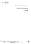
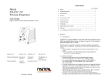
2.3 Dosiergerät 8035 Inline Abmessungen (mm)
88
21
91
180
88
H
mm
06
134
08
134
15
139
20
137
25
137
32
140
40
144
50
151
65
151
114
75
105
H
DN
104
116
Die Größe H ist von dem
Anschluss-Typ und Werkstoff
des Fittings unabhängig.
Fig. 1 Dosiergerät 8035 Abmessungen
D-6-
DOSIERGERÄT 8035
2 BESCHREIBUNG
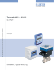
2.4 Technische Daten
Rohrdurchmesser
DN6 bis DN65
Umgebung
Umgebungs- und
Lagertemperatur
0 bis 60 °C
Relative Feuchtigkeit
max 80 %, nicht kondensierend
Schutzart
IP 65
Durchflussmessung
Messbereich
0.3 bis 10 m/s
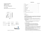
Messgenauigkeit
1. Mit anlagespezifischer Kalibrierung oder Teach-In:
≤ ± 0.5% v.E. (bei 10 m/s) *
2. Mit Standard-K-Faktor:
≤ ± (0.5% v.E. + 2.5% v.M.) *
Fehler max. [%]
10
v.E. = vom Endwert
v.M. = vom Messwert
8
6
0.5%
v . E. + 2 5. %
v . M.
0.5%
v. E .
4
2
-2
-4
-6
-8
-10
1
2
3
4
5
6
7
8
9
10
Typische Bürkert Kurve
Standard Kalibrierung
Kalibrierung mit Teach-In
Flüssigkeitsgeschwindigkeit [m/s]
Linearität
≤ ± 0.5% v.E. (bei 10 m/s) *
Wiederholbarkeit
0.4% v.M. *
(*) Unter Referenzbedingungen d.h. Messmedium Wasser, Umgebungs- und Wassertemperatur
20 ° C, Berücksichtigung der Mindestein- und Auslaufstrecken, angepasste Rohrleitungabmessungen.
v.E = vom Endwert (10 m/s); v.M = vom Messwert
D-7-
DOSIERGERÄT 8035
3 INSTALLATION
Medium
Druckklasse
PN 10 oder PN16, vom Fitting-Werkstoff abhängig;
Siehe Druck-Temperatur-Diagramm, § 3.1
Max. Mediumstemperatur
PVC : 50°C
PP, PVDF, Edelstahl, Messing: 100°C
Max. Viskosität
300 cSt.
Max Feststoffanteil
1%
Elektrische Daten
Versorgungsspannung
12-30 VDC, gefiltert u. geregelt, oder
115/230 VAC, je nach Ausführung
Stromaufnahme
≤ 70 mA, ohne E/A-Aufnahme
IN1 bis IN4 Eingänge
(Dosierungsmenge Auswahl)
4 Binäreingänge, 5-30 VDC, 3,3 kΩ-Impedanz
OUT-Ausgang, Anzeige des
Dosierungsstatus
Transistor NPN, Open Kollektor,
0 - 30 VDC, 100 mA, geschützt,
4 mögliche Zustände (siehe § 4.1.4)
Relais-Ausgänge
2 Relais, 3 A, 230 VAC, frei einstellbar
Verkabelung
Durch abgeschirmtes Kabel,
1,5 mm2 max. Querschnitt, 50 m max. Länge
Werkstoffe
Gehäuse
Deckel mit Klappe
Frontanzeige
Schrauben
Kabelverschraubungen
PC
PC
Polyester
Edelstahl
PA
D-8-
DOSIERGERÄT 8035
3 INSTALLATION
3.1 Allgemeine Hinweise zum Einbau
- Das Dosiergerät 8035 kann nur für Messungen von reinen, flüssigen,
wasserähnlichen Medien verwendet werden (Festanteil max: 1%,
Viskosität max. 300 cSt ).
- Das Gerät ist nicht für die Dosierung von Gasen geeignet.
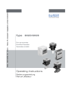
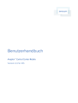
Entsprechend den verwendeten Fittingwerkstoffen muss deren Druck-Temperatur-Abhängigkeit berücksichtigt werden.
P bar
16
15
14
13
12
PVC + PP
11
10
9
PVDF
8
7
6
5
4
3
2
1
0
-50 -30 -10
Anwendungsbereich
Metall (PN16)
PVDF (PN10)
PVC (PN10)
PP (PN10)
+10
+30
+50
+70
+90 +110 +130
T °C
Fig. 2 Druck-Temperatur-Diagramm
Einbauvorschriften
Um das Fitting auf die Rohrleitung einzubauen, spezifische Einbau-vorschriften des Fittings
beachten.
Die passende Rohrabmessung wird gemäß dem Durchfluss-Diagramm ausgewählt.
Das Gerät muss vor dem Regen, vor Ultraviolettbestrahlung und elektromagnetischen Störungen geschützt werden.
3.2 Einbau
1. Beim Einbau des Fittings "1" in die
Rohrleitung, müssen die Einbauvorschriften
beachtet werden (siehe § 3.1).
2. Das Elektronikmodul SE35 "2" mit dem
Bajonett in das Fitting S030 einschieben
und um 30° verdrehen.
3. Mit der seitlichen Schraube "3" die
Einheit sichern.
4. Elektrischer Anschluss § 3.3.
2
3
1
D-9-
DOSIERGERÄT 8035
3 INSTALLATION
3.3 Elektrischer Anschluss
3.3.1 Allgemeine Hinweise zum elektrischen Anschluss
O
O
Das Gerät darf nicht bei angeschlossenem Netzkabel geöffnet werden.
Es ist ratsam, Sicherheitsvorrichtungen zu installieren:
Stromversorgung: Sicherung (250 mA) und ein Schalter.
Relais: Höchstens 3 A-Sicherung und Überlastschalter (je nach
Anwendung).
O
Nur abgeschirmte Kabel mit einer Temperaturbeständigkeit bis mindestens 80°C
verwenden.
O
Bei normalen Betriebsbedingungen kann das Messsignal über ein abgeschirmtes
Kabel mit einem Querschnitt von 0,75 mm2 übertragen werden.
O
Die Signal-Leitung darf nicht in Kontakt mit stromführenden Leitungen mit höherer
Spannung oder Frequenz installiert werden.
O
Wenn eine kombinierte Installation unumgänglich ist, sollten ein Mindestabstand
von 30 cm eingehalten werden.
O
Bei Verwendung eines einzigen Kabels muss der Kabeldurchmesser zwischen 6 und
12 mm liegen; Wenn zwei Kabel gebraucht werden, setzen Sie die Mehrwegdichtung
ein und verwenden Sie Kabel mit einem 4-mm-Durchmesser.
O
Es ist eine gefilterte und geregelte 12-30 VDC Stromversorgung zu verwenden.
Vergewissern Sie die Äquipotentialität der Installation (Stromversorgung - Gerät Flüssigkeit):
- Die verschiedene Erdungspunkte der Installation müssen aneinander
angeschlossen sein, damit die zwischen zwei Erdungspunkten
möglicherweise erzeugten Potentialdifferenzen beseitigt werden.
- Es muss auf vorschriftsmäßige Erdung der Abschirmung geachtet werden.
- Erden Sie den negativen Anschluss der Versorgungsquelle, um
Gleichtaktströme zu unterdrücken. Ist eine direkte Erdung unmöglich,
schließen Sie ein 100 nF/50 V-Kondensator zwischen dem negativen Anschluss
der Versorgungsquelle und der Erde.
Geben Sie darauf besonders acht, wenn das Gerät auf Kunststoffrohren
installiert wird, weil keine direkte Erdung möglich ist.
Zur Ordnungsgemäßen Erdung müssen alle die sich in der Nähe des Geräts befindenden
metallischen Apparate, wie Ventile oder Pumpen, an den selben Erdungspunkt angeschlossen werden.
O
D-10-
DOSIERGERÄT 8035
3 INSTALLATION
Prinzip einer Äquipotentialität:
Versorgung
12-30VDC
+
(*)
Metallische Rohre
diese Verbindung wird an die
Elektronikplatine ausgeführt
Versorgung
12-30VDC
+
-
Geräte wie Ventil,
Pumpe, usw...
(*)
Kunststoffrohre
diese Verbindung wird an die
Elektronikplatine ausgeführt
(*) ist keine direkte Erdung möglich, schließen Sie einen 100 nF/50V-Kondensator zwischen dem negativen Anschluss
der Versorgungsquelle und der Erde an.
D-11-
DOSIERGERÄT 8035
3 INSTALLATION
3.3.2 Einsatz der Kabelschellen
Bevor Sie das Gerät verkabeln, fädeln Sie die mitgelieferten Kabelschellen in Elektronikplatine bzw. 115/230 VAC-Versorgungsplatine, wenn vorhanden, ein.
Fig. 3 Einsatz der Kabelschellen
3.3.3 Einstellung der Schalter SENSOR INPUT bzw. SENSOR SUPPLY
Bevor Sie das Gerät verkabeln, überprüfen Sie bitte die korrekte Einstellung der beiden
Schalter der Elektronikplatine.
8035 Batch
Kompakt-Ausführungen
SENSOR INPUT
Schalter
NPN
D-12-
SENSOR SUPPLY
Schalter
wirkungslos
DOSIERGERÄT 8035
3 INSTALLATION
3.3.4 Elektrischer Anschluss, 12-30 VDC
Bevor Sie das Gerät verkabeln, lesen Sie bitte § 3.3.1, 3.3.2 und 3.3.3.
Schraube aufdrehen und durchsichtige Klappe heben. Schrauben aus der Frontanzeige
herausdrehen und Deckel abnehmen. Anschließend Kabel durch die Kabelverschraubungen ziehen und laut folgenden Anschlussplan anklemmen.
Die unverwendete Kabelverschraubung muss mittels der mitgelieferten
Verstopfung verstopft werden, um die Dichtheit des Geräts zu gewissern.
Die Kabelverschraubung aufschrauben, dann die Verstopfung einschieben
und die Kabelverschraubung wieder zuschrauben.
Schalter nicht unter Spannung einstellen!
Abschirmung des Kabels der Binäreingänge und des
OUT-Ausgangs
Neutralleiter
L+ (12-30 VDC)
L- (0V)
Abschirmung des Versorgungskabels
"Anzeige des Dosierungsstatus"-Ausgang
{
Binäreingänge, Auswahl der
Dosiermenge
1
PE
LPE
PE
L+
IN3
IN4
siehe § 3.3.3
Supply
12..30Vdc
BINARY
COIL
COIL SENSOR
NC
2 3 4 PE
L+
(L+)-12V
REL2
SENSOR SUPPLY
NPN
SENSOR INPUT
Nicht verwendet
REL1
NPN SENSOR
1 PULSE INPUT
2 - SUPPLY
3 +
4 NC
OUT
COMMON
IN1
IN2
1 2 3 4 5 6 7 8 9 10 11
Anschlusspunkte der
Kabel mittels mitgelieferten
Kabelschellen
(siehe § 3.3.2)
3A/230VAC
FLOW SENSOR
Anschluss des DurchflussSensors
Magnetventil
Type 121
Relais-Kabel obligatorisch mittels
mitgelieferten kabelschellen befestigen (siehe § 3.3.2)
Magnetventil
Type 142
Bei dieser Ausführung kann die Spannungsversorgung des Dosiergeräts für die Binäreingänge IN1 bis IN4 und den Ausgang OUT verwendet werden: In diesem Fall wird Klemme 6
(COMMON) an Klemme 9 (L-) verbunden.
Fig. 4 Anschluss des 8035, 12-30 VDC
D-13-
DOSIERGERÄT 8035
3 INSTALLATION
3.3.5
Elektrischer Anschluss, Kompakt-Ausführung, 115/230 VAC
- Bevor Sie das Gerät verkabeln, lesen Sie bitte § 3.3.1, 3.3.2 und 3.3.3.
- Bei dieser Ausführung kann die Spannungsversorgung des
Dosiergeräts nicht für die Binäreingänge IN1 bis IN4 und den Ausgang
OUT verwendet werden.
Schraube aufdrehen und durchsichtige Klappe heben. Schrauben aus der Frontanzeige
herausdrehen und Deckel abnehmen. Anschließend Kabel durch die Kabelverschraubungen ziehen und laut folgenden Anschlussplan anklemmen.
Die unverwendete Kabelverschraubung muss mittels der mitgelieferten
Verstopfung verstopft werden, um die Dichtheit des Geräts zu gewissern.
Die Kabelverschraubung aufschrauben, dann die Verstopfung einschieben
und die Kabelverschraubung wieder zuschrauben.
Schalter nicht unter Spannung einstellen.
Abschirmung des Kabels der Binäreingänge und des
OUT-Ausgangs
Neutralleiter
"Anzeige des Dosierungsstatus"-Ausgang
Binäreingänge, Auswahl der
Dosiermenge
roter Draht *
schwarzer Draht *
* im Werk verdrahtet
gelber Draht *
{
Auswahl der Spannungsversorgung 115/230 VAC
PE
LPE
IN3
IN4
PE
L+
Supply
12..30Vdc
BINARY
COIL
COIL SENSOR
NC
2 3 4 PE
L+
REL2
NPN
siehe § 3.3.3
SENSOR INPUT
(L+)-12V
SENSOR SUPPLY
125 mA
REL1
1
OUT
COMMON
IN1
NPN SENSOR
1 PULSE INPUT
2 3 + SUPPLY
4 NC
230V
Nicht verwendet
IN2
1 2 3 4 5 6 7 8 9 10 11
Anschlusspunkte der
Kabel mittels mitgelieferten
Kabelschellen
(siehe § 3.3.2)
3A/230VAC
L N
PE
{
FLOW SENSOR
{
{
Sicherung
Anschluss Relais 2
(siehe Beispiel Fig. 4)
Anschluss Relais 1
(siehe Beispiel Fig. 4)
Anschluss der
115/230 VAC
Versorgungsspannung
Relais-Kabel obligatorisch mittels
mitgelieferten kabelschellen befestigen (siehe § 3.3.2)
Fig. 5 Anschluss des 8035, 115/230 VAC
D-14-
DOSIERGERÄT 8035
4 BEDIENUNG
Die Bedienung gliedert sich in 3 Ebenen.
A) Hauptmenü
Der Benutzer steuert in diesem Menü die Dosierung mit Hilfe der Tastatur (Start, Pause,
Reset, Stop), wobei er den Durchfluss sowie den Wert der Ausgangsmenge während des
Dosiervorgangs anzeigen kann. Die Werte des Haupttotalisators und Tagestotalisators
werden in diesem Menü angezeigt. Der Tagestotalisator kann auf Null zurückgestellt werden.
B) Kalibriermenü
Mit diesem Menü können die mit der Dosierung verbundenen Parameter (Sprachen, Maßeinheiten, K-Faktor, Dosieroption, Überlaufkorrektur, Alarm, Relaisschwellen) programmiert
werden.
In diesem Menü wird die gleichzeitige Rückstellung der 2 Totalisatoren vorgenommen.
C) Testmenü
Das Testmenü bietet dem Benutzer die Möglichkeit, die Binäreingänge (Fernsteuerung) zu
überprüfen und die Arbeitsweise der Relais zu simulieren.
Mit Hilfe dieses Menüs kann die Rotationsfrequenz des Schaufelrades gemessen werden.
4.1 Bedien- und Anzeigeelemente des Dosiergerätes 8035
Inkrementiertaste
Zahlenwert je Stelle
verändern von 0 bis 9
Menü durchlaufen
(Numerische Werte)
Bestätigungs-taste
Eingabe und Menüpunkte
Wahltaste
Stelle auswählen
Menü durchlaufen
Relais 1 Status
D-15-
Relais 2 Status
DOSIERGERÄT 8035
4 BEDIENUNG
4.2 Beschreibung der verschiedenen Dosieroptionen
Die Dosieroptionen werden im Untermenü «OPTION» des Kalibriermenüs ausgewählt (siehe
§ 4.4.4).
4.2.1 Option «LOK.HAND»
Bei Wahl dieser Option wird die Meldung «BATCH M» im Hauptmenü angezeigt. Hierdurch
kann eine mit Hilfe der Tastatur zu definierende Menge dosiert werden (siehe § 4.3.1).
4.2.2 Option «LOK.MEM»
Bei Wahl dieser Option wird die Meldung «BATCH A» im Hauptmenü angezeigt. Hierdurch
kann eine von insgesamt 7 Mengen dosiert werden, die zuvor mit Hilfe der Tastatur in den
Speicher eingegeben wurden (siehe § 4.3.2).
4.2.3 Option «MEM+HAND»
Bei Wahl dieser Option werden die Meldungen «BATCH M» und «BATCH A» im Hauptmenü angezeigt. Hierdurch kann eine manuelle oder automatische Dosierung vorgenommen
werden (siehe § 4.3.1 und § 4.3.2).
D-16-
DOSIERGERÄT 8035
4 KONFIGURIERUNG
4.2.4 Option «EXT.MEM»
12-30 VDC
Mit dieser Option kann die Dosierung einer von insgesamt 7 Mengen gesteuert werden, die
zuvor mit Hilfe der Binäreingänge durch Fernerfassung in den Speicher eingegeben wurden
(siehe § 4.2.2). Das nachstehende Beispiel beschreibt die verschiedenen Anschlusssmöglichkeiten.
+
-
Auswahl Dosiermenge
Start/stop
PE
LPE
PE
L+
IN3
IN4
OUT
COMMON
Dosiergerät 8035 INLINE
IN2
IN1
1 2 3 4 5 6 7 8 9 10 11
Anzeige
Supply
12..30Vdc
Fig. 6 Anschluss-Beispiel
Die Auswahl der zu dosierenden Menge aus dem Speicher (von 1 bis 7) erfolgt durch Codierung mit Hilfe der Binäreingänge IN1, IN2 und IN3. Die nachstehende Tabelle gibt den
Zustand jedes einzelnen Eingangs entsprechend dem gewünschten Volumen (Menge) an:
Volumen
V1
V2
V3
V4
V5
V6
V7
Eingang IN1
1
0
1
0
1
0
1
Eingang IN2
0
1
1
0
0
1
1
Eingang IN3
0
0
0
1
1
1
1
1: Eingang aktiviert (Schalter geschlossen)
0: Eingang inaktiviert (Schalter offen)
Der Binäreingang IN4 übernimmt die Funktion Start/Pause (beispielsweise Druckknopf)
Bei dem Ausgang OUT handelt es sich um einen NPN Transistorausgang (Open collector),
der die Informationen über den Zustand des Dosiergerätes weiterleitet.
Er ermöglicht beispielsweise den Anschluss einer Anzeigeleuchte. Folgende Zustände
werden hierbei angezeigt:
Anzeigeleuchte leuchtet nicht auf:
keine laufende Dosierung
Anzeigeleuchte leuchtet auf:
laufende Dosierung
Langsames Blinken (1 Hz):
laufende Dosierpause
Schnelles Blinken (3,5 Hz):
Alarm (Problem während des Dosiervorgangs).
D-17-
DOSIERGERÄT 8035
4 KONFIGURIERUNG
4.2.5 Option «EXT.[T]»
Mit dieser Option kann die Dosierung einer Menge gesteuert werden, die sich proportional
zur Aktivierungsdauer des Binäreingangs 1 verhält (siehe § 4.3.3). Die Proportionalität
gestaltet sich wie folgt:
X= dosierende Menge = (A x t) + B
A: Proportionalitätskoeffizient (l/s,...)
B: Offset (l,...)
t: Aktivierungsdauer von Eingang 1 (s,...)
X = dosierende Menge
Die Einheiten und Koeffizienten A und B sind vom Benutzer zu programmieren.
Impulsmerkmale:
Tmin: 100 ms
Tmax: 300 s.
Auflösung: 5 ms
Mindestzeit zwischen 2 aufeinanderfolgenden Impulsen:100 ms
Anwendungsbeispiele:
- "1" Abfüllen von Kanistern von 5, 10 und 50 Litern. Folgende Werte können programmiert
werden:
A = 5 l/s
B=0l
Die Aktivierungsdauer des Binäreingangs 1 gestaltet sich entsprechend den jeweiligen
Volumen wie folgt:
X=Volumen (l)
5
10
50
t=Dauer (s)
1
2
10
- "2" Dosierung von Chemikalienvolumen entsprechend der gewünschten Konzentration.
Volumen: 110, 120, 130 und 150 Liter.
Folgende Werte können programmiert werden:
A = 5 l/s
B = 100 l
Die Aktivierungsdauer des Binäreingangs 1 gestaltet sich je nach Volumen wie folgt:
X=Volumen (l)
t=Dauer (s)
110
120
130
2
4
6
150
10
Bemerkungen:
- Die Aktivierungsdauer des Binäreingangs muss stets unter der tatsächlichen Abfüllzeit
liegen. Bei der Wahl der Koeffizienten A und B muss eine Sicherheitsspanne berücksichtigt
werden.
- Die Koeffizienten A und B sind derart zu wählen, dass sich die Aktivierungsdauer des
Binäreingangs 1 «angemessen» gestaltet. Im "2". Beispiel hätte man A = 100 l/s und B =
0 l wählen können. Die Aktivierungsdauer hätte entweder 1,1 oder 1,2 oder 1,3 oder 1,5 s
betragen können. In diesem Fall hätten sich die Dosierungen als weniger genau erwiesen.
D-18-
DOSIERGERÄT 8035
4 KONFIGURIERUNG
4.3 Hauptmenü
Im Hauptmenü werden folgende Größen angezeigt:
0......9
BATCH M
Dosierung im manuellen Betriebsmodus (siehe § 4.3.1). Erscheint
nur, wenn die Dosieroption «LOK.HAND» oder «MEM+HAND» im
Kalibriermenü gewählt wurde (siehe Kalibriermenü § 4.4).
BATCH A
Dosierung im automatischen Betriebsmodus (siehe § 4.3.2).
Erscheint nur, wenn die Dosieroption «LOK.MEM» oder
«MEM+HAND» im Kalibriermenü gewählt wurde (siehe Kalibriermenü § 4.4).
Haupttotalisator in der gewünschten Maßeinheit (siehe Kalibriermenü § 4.4). Rückstellung im Kalibriermenü.
24563 L
456 L.
Tagestotalisator in der gleichen Maßeinheit wie der Haupttotalisator. Eine Dezimalpunkt hinter der Maßeinheit unterscheidet ihn
vom Haupttotalisator. Zum Rückstellen die beiden Tasten 0......9
2 Sekunden lang gleichzeitig drücken.
Die folgenden Unterprogramme beschreiben die verschiedenen Dosieroptionen mit den im
Hauptmenü angezeigten Meldungen. Die grauen Zeichen blinken an der Anzeige.
4.3.1 Dosierung im manuellen Betriebsmodus (Option «LOK.HAND» oder
«MEM+HAND»)
Anhand des manuellen Betriebsmodus kann die Dosierung einer Menge vorgenommen
werden, die zuvor mit Hilfe der Tastatur eingegeben wurde.
BATCH M
ENTER
00000 L
0......9
00100 L
Eingabe der zu
dosierende Menge
ENTER
* Sie können die Dosierung auch
durch Drücken des Binäreingangs 4
'Start/Pause' (siehe 4.2.1) starten.
*
OK
J/N
OK
J/N
Countdown des
Wertes bis 0
ENTER
00100 L
ENTER
Die zu dosierende Menge muss höher sein als 6 durch das Flügelrad erzeugten Pulse. Die
Eingabe einer ungültigen Menge führt zurück zur Option «BATCH M».
Meldung «ALARM» während des Dosiervorganges: Dosierproblem (siehe § 5.1).
Während der Dosierung der programmierten Menge können der Durchfluss angezeigt,
eine Pause eingelegt, ein Reset vorgenommen oder die Dosierung beendet werden (siehe
§ 4.3.4 und § 4.3.5).
D-19-
DOSIERGERÄT 8035
4 KONFIGURIERUNG
4.3.2 Dosierung im automatischen Betriebsmodus
(Option «LOK.MEM», «MEM+HAND» oder «EXT.MEM»)
Mit Hilfe des automatischen Betriebsmodus kann die Dosierung einer der 7 zuvor in die
Bibliothek eingegebenen Mengen vorgenommen werden. Die Dosierung kann entweder mit
Hilfe der Tastatur oder über die Binäreingänge gesteuert werden.
A) Steuerung der Dosierung mit Hilfe der Tastatur (Option «LOK.MEM» oder
«MEM+HAND»)
Countdown des
Wertes bis 0
1 s.
BATCH A
ENTER
V1
250
L
V2
50
L
V7
1250
L
ENDE
ENTER
*
OK
J/N
ENTER
OK
J/N
ENTER
250
L
* Sie können die Dosierung
auch durch Drücken des
Binäreingangs 4 'Start/Pause'
(siehe 4.2.1) starten.
ENTER
Die Mengen (V1 bis V7) mit ungültigen Werten werden nicht angezeigt.
B) Steuerung der Dosierung über die Binäreingänge (Option «EXT.MEM»)
Countdown des
Wertes bis 0
1 s.
2885 L
1
2
3
V2
50
L
4
38
L
Aktivierung des Eingangs 4
(beispielsweise Druckknopf) für
den Dosierstart
Wahl des Volumens im Speicher
durch Codierung mit Hilfe der
Binäreingänge 1, 2 und 3
Meldung «ALARM» während des Dosiervorgangs: Dosierproblem (siehe § 5.1).
Während der Dosierung der gewählten Menge können der Durchfluss angezeigt, eine Pause eingelegt, ein Reset vorgenommen oder die Dosierung beendet werden (siehe § 4.3.4
und § 4.3.5).
D-20-
DOSIERGERÄT 8035
4 KONFIGURIERUNG
4.3.3 Proportional zu einer Pulsdauer wirkende Dosierung (Option «EXT.[T]»)
Mit Hilfe dieser Option kann die Dosierung einer Menge vorgenommen werden, die sich
proportional zur Aktivierungsdauer des Binäreingangs 1 verhält. Folgende Meldungen werden während des Dosiervorgangs im Hauptmenü angezeigt:
Countup des
Wertes
Anzeige
Totalisator
2885 L
38
1
L
+
-
12-30 VDC
Aktivierungsdauer
proportional zum zu
dosierenden Volumen
Auswahl Dosiermenge
Anzeige
PE
LPE
PE
L+
IN3
IN4
Dosiergerät 8035 INLINE
OUT
COMMON
IN2
IN1
1 2 3 4 5 6 7 8 9 10 11
Supply
12..30Vdc
Fig. 7 Anschlussbeispiel
Meldung «ALARM» während des Dosiervorgangs: Dosierproblem (siehe § 5.1).
Während der Dosierung der gewählten Menge können der Durchfluss angezeigt, eine Pause eingelegt, ein Reset vorgenommen oder die Dosierung beendet werden, jedoch nur mit
Hilfe der Tastatur (siehe § 4.3.4 und § 4.3.5).
4.3.4 Durchfluss- und Ausgangsmengenanzeige während des Dosiervorgangs
Zur Anzeige des Durchflusses und der Ausgangsmenge während des Dosiervorgangs ist
kurz zu betätigen. Dies gilt unabhängig von der gewählten Dosierlediglich die Taste
option.
Countdown
des laufenden
Dosierwertes
221
L
Ausgangsmenge
250
2 s.
L
Durchfluss
2.34 L/S
2 s.
Automatische Rückkehr nach 2 s.
D-21-
DOSIERGERÄT 8035
4 KONFIGURIERUNG
4.3.5 Funktion Pause/Reset
Ein Dosiervorgang kann momentan oder endgültig gestoppt werden (aber nicht bei der
Option EXT [T]).
a) Optionen MEM+HAND, LOK.MEM, LOK.HAND:
Countdown
des laufenden
Dosierwertes
221
L
WEITER
ENTER
Die aktuelle
221
ENTER
L Dosierung wird
*
*
RESET
fortgeführt
Das Gerät ist für eine neue Dosierung bereit (siehe 4.3.1)
ENTER
*
(*) Bei den Optionen LOK.HAND, LOK.MEM oder MEM+HAND kann auch der Binäreingang 4 'Start/Pause' gedruckt
werden.
b) Option EXT.MEM
**
Countdown des laufenden
Dosierwertes
221
L
**
4
221
4
Die aktuelle Dosierung
L wird fortgeführt
WEITER
Pause
RESET
1
2
3
4
«Null»-Stellung: kein
Eingang aktiviert
Das Gerät ist
für eine neue
Dosierung
bereit (siehe
4.3.2)
c) Option EXT [T]
Countdown des laufenden
Dosierwertes
221
L
**
4
Pause
WEITER
**
4
221
L
Die aktuelle Dosierung
wird fortgeführt
"Reset" kann nur mittels der
Tastatur gewählt werden.
RESET
**
4
Das Gerät ist für eine neue Dosierung bereit (siehe 4.3.3)
(**) Bei den Optionen EXT.MEM und EXT [T] kann auch die Taste ENTER gedrückt werden.
D-22-
DOSIERGERÄT 8035
4 BEDIENUNG
4.4 Kalibriermenü:
ENTER
gleichzeitig während 5 s drücken.
In diesem Menü werden folgende Größen programmiert:
SPRACHE
Wahl der Sprache der einzelnen Meldungen (deutsch, englisch,
französisch, italienisch).
EINHEIT
Wahl der Maßeinheit für das zu dosierende Volumen, die Durchfluss- und die Totalisatorenanzeige.
K-FAKTOR
OPTION
UBERL. JA
Eingabe des K-Faktors oder automatische Ermittlung durch die
«Teach in»-Funktion.
Wahl des Dosiermodus.
Mögliche Berücksichtigung der Überlaufkorrektur.
ALARM
Zugriff zu Optionen und Programmierung der Alarmverzögerung.
RELAIS
Parametrieren der Relais: Funktion, Verzögerung, Umkehrung,
usw.
TOTAL
ENDE
Gleichzeitige Rückstellung der 2 Totalisatoren.
Rückkehr zum Hauptmenü und Speicherung der neuen Kalibrierparameter.
4.4.1 Sprache
SPRACHE
ENTER
ENGLISH
DEUTSCH
FRANCAIS
ITALIANO
ESPANOL
EINHEIT
ENTER
D-23-
Die gewünschte Sprache wird
durch die Enter-Taste bestätigt
und sofort aktiv.
DOSIERGERÄT 8035
4 BEDIENUNG
4.4.2 Einheiten
EINHEIT
ENTER
BATCH
m LITRE
ENTER
ENTER
LIT/SEC
LIT/MIN
LITRE
0......9
M3
LIT/H
US GAL
M3/MIN
IMP GAL
M3/H
USGAL/S
USGAL/M
USGAL/H
IMPGAL/S
IMPGAL/M
IMPGAL/H
TOTAL
ENTER
LITRE
ENTER
M3
US GAL
IMP GAL
K-FAKTOR
ENTER
Hinweis: Die Rückkehr in das Hauptmenü erfolgt nur über das Untermenü "TOTAL".
D-24-
DOSIERGERÄT 8035
4 BEDIENUNG
4.4.3 K-Faktor
In diesem Menü wird der K-Faktor der Armatur eingegeben (siehe Bedienungsanleitung
Fitting S030). Mit dem "Teach in", kann aber der K-Faktor, spezifisch zu den Applikationsbedigungen, praktisch ermittelt werden. Dazu muss der Benutzer nur eine bekannte Menge
durch seine Anlage fließen lassen.
Beispiel: Um die Menge genau bestimmen zu können, füllt der Benutzer z. B. einen Behälter von 100 Liter. Bei der Meldung "TEACH JA" drückt er die Enter-Taste, um die Messung
zu starten. Die Meldung "ABF ENDE" (Abfüllen Ende) erscheint. Dann schaltet er die
Pumpe ein (oder macht ein Ventil auf). Wenn sein Behälter leer ist, schaltet er die Pumpe
ab (oder macht das Ventil zu). Ein Drücken auf die Enter-Taste stoppt die Messung. Der
Benutzer wird dann aufgefordert, die Menge (100 Liter) einzugeben. Nach Bestätigung wird
der berechnete K-Faktor angezeigt.
Hinweis: Es wird der zuletzt eingegebene oder bestimmte K-Faktor in Anspruch genommen.
K-FAKTOR
ENTER
TEACH N
ENTER
K=000.00
0......9
ENTER
OPTION
TEACH JA
ENTER
Start der Messung
Eingabe des K-Faktors gemäß
Tabellen
K=046.60
ABF ENDE
ENTER
0000.0 L
Stop der Messung
0......9
Eingabe der gemessenen
Menge. Die Einheit ist die
selbe wie für den Durchfluss
OPTION
ENTER
K=044.12
ENTER
0200.0 L
Anzeige des
berechneten K-Faktors
Bemerkung: Die Dezimalstelle wird durch gleichzeitigen Druck der Tasten 0......9
versetzt. Sie wird, von der blinkenden Stelle aus, stets nach rechts verschoben. Drei Positionen
sind möglich: «00000», «0000.0» und «000.00».
Einstellbereich: 0,01 bis 99999.
4.4.4 Dosieroptionen
Der Benutzer wählt in diesem Untermenü die gewünschte Dosieroption, nämlich: LOK.
MEM, LOK.HAND, MEM+HAND, EXT.MEM oder EXT.[T]. Für nähere Einzelheiten zu diesen
Optionen siehe § 4.2.
D-25-
DOSIERGERÄT 8035
4 BEDIENUNG
OPTION
ENTER
LOK.MEM
ENTER
V7=00000
V1=00000
0......9
0......9
V1=00100
V7=00700
ENTER
UBERL. JA
ENTER
LOK.HAND
ENTER
UBERL. JA
MEM+HAND
ENTER
V7=00000
V1=00000
0......9
0......9
V1=00100
V7=00700
ENTER
UBERL. JA
ENTER
EXT.MEM
ENTER
V7=00000
V1=00000
0......9
0......9
V1=00100
V7=00700
ENTER
UBERL. JA
ENTER
EXT. [T]
ENTER
A=0000/S
0......9
A=0005/S
ENTER
B=0000 L
0......9
UBERL. JA
ENTER
B=0050 L
Bei der Eingabe der Volumen V1 bis V7 entspricht die Maßeinheit der, die für die zu dosierende Menge gewählt wird (siehe Kalibriermenü).
Bemerkung: Die Dezimalstelle wird durch gleichzeitigen Druck der Tasten 0......9
schoben. Sie wird, von der blinkenden Stelle aus, stets nach rechts verschoben.
D-26-
ver-
DOSIERGERÄT 8035
4 KONFIGURIERUNG
4.4.5 Überlaufkorrektur
Mit dem Dosiergerät 8035 INLINE kann eine Überlaufkorrektur vorgenommen werden. Sie
besteht aus der Speicherung der Flüssigkeitsmenge, die noch nach dem Schließen des
Ventils abläuft, damit diese von der nachfolgenden Dosierung abgezogen werden kann. Der
Benutzer aktiviert oder deaktiviert in diesem Untermenü die Überlaufkorrektur.
UBERLAUF
UBERL. N
ENTER
ALARM
ENTER
UBERL. JA
4.4.6 Alarm
Hier kann während (Menüpunkt 'WAHREND') und/oder nach (Menüpunkt 'NACH') der
Dosierung der Alarm ein- oder ausgeschaltet werden.
In diesem Menüpunkt wird auch die Alarmauslösezeit festgelegt. Der Alarm wird durch die
Meldung «ALARM» angezeigt. Diese Information wird ebenfalls an der Klemme
Nr. 5 (Ausgang Transistor Open Collector) und am Relais Nr. 2 bereitgestellt, falls dieses
als Alarmrelais konfiguriert wurde.
Für die Voraussetzungen zur Auslösung des Alarms siehe Punkt 5.
ALARM
ENTER
WAHREND
EIN
ENTER
ENTER
VER1= 000
0......9
VER1= 015
AUS
NACH
EIN
ENTER
ENTER
ENTER
ENTER
VER2= 000
0......9
VER2= 015
AUS
ENTER
ENTER
RELAIS
Einstellbereich: 0 bis 999 Sek.
Bemerkung: Die Alarmauslösezeit muss die Überlaufkorrektur (siehe Punkt 4.4.5) berücksichtigen, falls diese aktiv sein sollte.
D-27-
DOSIERGERÄT 8035
4 KONFIGURIERUNG
4.4.7 Relais
Das Gerät verfügt über 2 Relais:
- Das Relais 1 steuert ausschließlich die Öffnung des Hauptventils (großer Durchfluss). Eine
Aktivierungsverzögerung kann festgelegt sowie die Wirkungsrichtung umgekehrt werden,
wobei der Benutzer den Prozentsatz der zu dosierenden Menge einprogrammieren kann,
der durch das Hauptventil (großer Durchfluss) laufen muss. Diese Möglichkeit setzt voraus,
dass das Relais 2 ein Nebenventil (geringer Durchfluss) steuert, um den Rest der Menge zu
dosieren.
- Das Relais 2 kann in 3 verschiedenen Konfigurationen eingesetzt werden: Alarm, Dosierstop und Steuerung des Nebenventils. Bei jeder dieser Konfigurationen kann die Wirkungsrichtung umgekehrt werden.
D-28-
DOSIERGERÄT 8035
4 KONFIGURIERUNG
RELAIS
ENTER
RELAIS 1
ENTER
VER= 000
0......9
VER= 020
ENTER
100 %
0......9
INV NEIN
INV JA
RELAIS 2
ENTER
ALARM
ENTER
85 %
ENTER
ENTER
INV NEIN
INV JA
TOTAL
ENTER
END DOSI
ENTER
INV NEIN
INV JA
TOTAL
ENTER
VENTIL
ENTER
INV NEIN
INV JA
TOTAL
ENTER
Bemerkungen:
- Entspricht der Prozentsatz bei der Konfigurierung des Relais 1 nicht 100, befindet sich
das Relais 2 automatisch im Betriebsmodus Ventilsteuerung. Die anderen Optionen sind
nicht mehr zugänglich.
- Das Relais 1 öffnet das Ventil nur, nachdem die eingegebene Zeitverzögerung abgelaufen
ist.
D-29-
DOSIERGERÄT 8035
4 KONFIGURIERUNG
4.4.8 Totalisator
Gleichzeitige Rückstellung der 2 Totalisatoren. Sie erfolgt endgültig, sobald der Benutzer
die Enter-Taste bei der Option «ENDE» im Kalibriermenü betätigt.
TOTAL
RES NEIN
ENTER
RES JA
ENDE
ENTER
4.5 Testmenü:
ENTER
0......9
gleichzeitig während 5 s drücken
Im Testmenü werden folgende Einstellungen und Überprüfungen vorgenommen:
EXT.STEU
Überprüfung der Binäreingänge im Betriebsmodus «EXT.MEM»
Anzeige der Pulsdauer im Betriebsmodus «EXT.[T]»
RELAIS 1
Überprüfung der Arbeitsweise des Relais 1.
RELAIS 2
Überprüfung der Arbeitsweise des Relais 2.
FREQUENZ
ENDE
Anzeige der Sensorfrequenz.
Rückkehr zum Hauptmenü und Speicherung der neuen Parameter.
4.5.1 EXT.STEU
Mit diesem Untermenü können der Anschluss der Binäreingänge bei der Dosieroption «EXT.
MEM» überprüft oder die Pulsdauer bei der Option «EXT [T]» angezeigt werden.
Option «EXT.MEM»
EXT.STEU
RELAIS 1
ENTER
ENTER
V1
V4
Anzeige der Volumen, die der Codierung der Binäreingänge
entsprechen (beispielsweise durch Betätigung des Drehschalters). Wird «—» angezeigt, entspricht die Codierung an den
Eingängen keinem Volumen.
D-30-
DOSIERGERÄT 8035
4 KONFIGURIERUNG
Option «EXT[T]»
Der Benutzer kann an dieser Stelle die an das Dosiergerät abgegebene Pulsdauer überprüfen.
EXT.STEU
ENTER
. . . . SEC
0.00 SEC
Abgabe eines
Impulses
RELAIS 1
5.35 SEC
Impulsende
ENTER
4.5.2 Überprüfung der Arbeitsweise der Relais
Bei dieser Option kann der Benutzer die Relais mit Hilfe der Tastatur betätigen, um ihre
einwandfreie Arbeitsweise zu überprüfen.
RELAIS 1
ENTER
REL ZU
REL AUF
RELAIS 2
ENTER
ENTER
REL ZU
REL AUF
ENTER
FREQUENZ
4.5.3 Frequenzanzeige
Anzeige der Rotationsfrequenz des Schaufelrades. Durch Betätigen der Enter-Taste wird
die Anzeige beendet und zum nächsten Menüpunkt übergegangen.
FREQUENZ
FIN
ENTER
15.25 HZ
ENTER
Bemerkung: Nach Betätigung der «Enter»-Taste bei der Meldung «FREQUENZ» wird das
Relais 1 (zum Öffnen des Ventils) aktiviert.
D-31-
DOSIERGERÄT 8035
5 WARTUNG
5.1 Fehlermeldungen
5.1.1 Meldung «ALARM»
MELDUNG "ALARM" WÄHREND EINER DOSIERUNG
Die Meldung «ALARM» erscheint während des Dosiervorgangs (unabhängig von der Dosieroption), falls das bzw. die Ventile geöffnet sind und das Dosiergerät keinen Durchfluss
ermittelt. Die Auslösezeit des Alarms wird im Kalibriermenü festgelegt (siehe Abs. 4.4.6).
Die durch den Alarm unterbrochene Dosierung kann entweder fortgeführt oder rückgestellt
werden:
a) Dosierung im manuellen oder automatischen Modus, durch LOK.HAND, LOK.
MEM oder MEM+HAND aktiviert
ALARM
WEITER
ENTER
Die aktuelle Dosierung
wird fortgeführt
ENTER
*
RESET
ENTER
*
Das Gerät ist für eine neue
Dosierung bereit (siehe
4.3.1 oder 4.3.2)
(*) Bei den Optionen LOK.HAND, LOK.MEM oder MEM+HAND kann auch der Binäreingang 4 'Start/Pause' gedruckt
werden.
b) Dosierung über die Binäreingänge, durch EXT.MEM aktiviert
4
ALARM
1
2
3
dann
**
4
RESET
Binäreingänge auf Null
zurückstellen
ODER
** Das Gerät ist für eine neue
Dosierung bereit (siehe
4.3.2)
1
2
3
WEITER
Binäreingänge auf die
Stellung der aktuellen
Dosierung setzen
(**) Bei den Optionen EXT.MEM und EXT [T] kann auch die Taste ENTER gedrückt werden.
D-32-
**
4
Die aktuelle
Dosierung wird
fortgeführt
5 WARTUNG
DOSIERGERÄT 8035
c) Dosierung über die Binäreingänge, durch EXT[T] aktiviert
ALARM
**
RESET
4
4
** Das Gerät ist für eine neue
Dosierung bereit (siehe
4.3.3)
"Weiter" kann nur mittels der
Tastatur gewählt werden.
WEITER
**
4
221
L
Die aktuelle Dosierung wird fortgeführt
(**) Bei den Optionen EXT.MEM und EXT [T] kann auch die Taste ENTER gedrückt werden.
MELDUNG "ALARM" NACH EINER DOSIERUNG
Die Meldung «ALARM» erscheint am Ende des Dosiervorgangs (unabhängig von der
Dosieroption), falls das bzw. die Ventile geschlossen sind und das Dosiergerät noch einen
Durchfluss nach Ablauf der Alarmauslösezeit ermittelt.
Bemerkung: Bei der Alarmzeit muss eine mögliche Überlaufkorrektur der Menge berücksichtigt werden, die noch nach dem Schließen des Ventils abläuft.
a) Dosierung im manuellen oder automatischen Modus, durch LOK.HAND, LOK.
MEM oder MEM+HAND aktiviert:
ALARM
ENTER
Das Gerät ist für eine neue
Dosierung bereit (siehe
4.3.1)
b) Dosierung über die Binäreingänge, durch EXT.MEM oder EXT [T] aktiviert:
ALARM
4
** Das Gerät ist für eine neue
Dosierung bereit (siehe
4.3.2)
(**) Bei den Optionen EXT.MEM und EXT [T] kann auch die Taste ENTER gedrückt werden.
D-33-
DOSIERGERÄT 8035
5 WARTUNG
5.1.2 Meldung «[T]ERROR»
Die Meldung «[T]ERROR» betrifft nur die Option «EXT[T]». Sie erscheint während des
Dosiervorgangs, falls die Pulsdauer 300 s beziehungsweise den Zeitraum überschreitet, der
zur Dosierung der entsprechenden Menge erforderlich ist.
Sie erscheint ebenfalls, sobald die zu dosierende Menge 100000 (l, m3, ...) überschreitet
beziehungsweise die Menge des laufenden Dosiervorgangs 100000 (l, m3, ...) erreicht hat
und der Impuls noch nicht beendet ist.
T [ERROR]
**
4
Das Gerät ist für eine neue Dosierung
bereit (siehe 4.3.3)
(**) Bei der Option EXT [T] kann auch die Taste ENTER gedrückt werden.
5.1.3 Meldung «FEHLER»
Wird die Meldung «FEHLER» angezeigt, sind die Kalibrierparameter verlorengegangen.
Nach Betätigung der ENTER-Taste erfolgt ein Rücksprung zum Hauptmenü, wobei das
Gerät jedoch die Grundkonfiguration annimmt (siehe § 5.3). Das Dosiergerät muss neu
programmiert werden. Tritt die Meldung wiederholt auf, senden Sie das Gerät bitte an Ihren
Lieferanten zurück.
5.2 Wartung des Messwertaufnehmers
Sind Installation und Einsatzbedingungen korrekt, benötigt das Dosiergerät keine besondere Wartung. Bei Ablagerungen kann der eingetauchte Teil des Sensors (Schaufelrad, Achse, Lager) mit Wasser oder einem für PVDF geeigneten Reinigungsmittel gereinigt werden.
5.3 Basis Einstellungen des 8035 bei Auslieferung
Sprache:
Maßeinheit Durchfluss:
Maßeinheit Totalisatoren:
Maßeinheit Dosierung:
K-Faktor:
Dosieroption:
Volumen V1 bis V7:
Englisch
l/s
l
l
001.00
MEM+MANU
00000
D-34-
Überlaufkorrektur:
Ja
Alarm WÄHREND: Ein, VER1 = 100
Alarm NACH:
Ein, VER2 = 100
Relais 1:
VER = 000
100%
Umkehrung:
nein
Relais 2:
VENTIL
Umkehrung:
nein
DOSIERGERÄT 8035
5 WARTUNG
Benutzer-Einstellungen des Dosiergerätes 8035 Nr:
Überlaufkorrektur:
Alarm WÄHREND: VER1 =
Alarm NACH:
VER2 =
Relais 1:
VER =
Sprache:
Maßeinheit Durchfluss:
Maßeinheit Totalisatoren:
Maßeinheit Dosierung:
K-Faktor:
Dosieroption:
Volumen V1 bis V7:
Umkehrung:
Relais 2:
Umkehrung:
D-35-
DOSIERGERÄT 8035
5 WARTUNG
5.4 Ersatzteil-Stückliste Dosiergerät Elektronikmodul 8035
Position
BestellNr.
Bezeichnung
1
Komplettes Gehäuse
425248
2
Deckel mit Klappe, Schrauben und Folie
553189
553171
3
Leiterplatte + Schutzplatte + Montageblatt
2+3
Deckel mit Klappe, Schrauben, Folie und Leiterplatte
425432
4
Versorgungsplatine 115/230 VAC
553168
5+7+8+10 Satz mit 2 Kabelverschraubungen M20x1,5
+ 2 Flachdichtungen aus Neopren für Kabelverschraubung
oder Verstopfung
+ 2 Schraubverstopfungen M20x1,5
+ 2 Mehrwegdichtungen 2x6 mm
449755
6+7+8
Satz mit 2 Reduktionen M20x1,5 / NPT1/2'' (Dichtung montiert)
+ 2 Flachdichtungen aus Neopren für Verstopfung
+ 2 Schraubverstopfungen M20x1,5
551782
9+10
Satz mit 1 Verschluss für Kabelverschraubung M20x1,5
+ 1 Mehrwegdichtung 2x6 mm für Kabelverschraubung
+ 1 EPDM-Dichtung (nicht verwendet)
+ 1 Montage-Blatt
551775
Satz mit 8 „FLOW“-Folien mit -“Relais“-Markierung
553192
Bedienungsanleitung Fitting Inline S030
426107
6
5
2
3
8
1
4
D-36-
9
10
7
DOSIERGERÄT 8035
D-37-
DOSIERGERÄT 8035
D-38-
TABLE OF CONTENTS
BATCH CONTROLLER 8035
1
INTRODUCTION ............................................................................................................ E-2
1.1
1.2
1.3
1.4
Unpacking and Control .............................................................................................................................................E-2
About this Manual.......................................................................................................................................................E-2
User's Responsibility for Safety ..............................................................................................................................E-2
Electromagnetic Compatibility ................................................................................................................................E-2
2
SPECIFICATION ............................................................................................................ E-3
2.1
2.2
2.3
2.4
Ordering table for electronic module SE35 Batch .............................................................................................E-3
Design and Measuring Principle .............................................................................................................................E-4
Dimensions Electronic housing 8035 Batch controller.....................................................................................E-5
Technical Data.............................................................................................................................................................E-6
3
INSTALLATION .............................................................................................................. E-8
3.1
3.2
3.3
Installation Guidelines ...............................................................................................................................................E-8
Process Mounting ......................................................................................................................................................E-8
Electrical connection .................................................................................................................................................E-9
3.3.1 Electrical connection recommendations ................................................................................................E-9
3.3.2 How to use the cable clips..................................................................................................................... E-11
3.3.3 Using switches SENSOR INPUT and SENSOR SUPPLY ............................................................. E-11
3.3.4 Electrical wiring, 12-30 VDC version ................................................................................................................ E-12
3.3.5 Electrical wiring, 115/230 VAC version .............................................................................................. E-13
4.
OPERATION AND CONFIGURATION.....................................................................E-14
4.1
4.2
Controller operating and Control elements .....................................................................................................................E-14
Description of the Dosing Options....................................................................................................................................E-15
4.2.1. «LOC.MANU» Option ...........................................................................................................................................E-15
4.2.2. «LOC.MEM» Option .............................................................................................................................................E-15
4.2.3. «MEM+MANU» Option ........................................................................................................................................E-15
4.2.4. «EXT.MEM» Option................................................................................................................................................E-16
4.2.5. «EXT.[T]» Option.....................................................................................................................................................E-17
Main menu ..............................................................................................................................................................................E-18
4.3.1. Dosage in manual mode ......................................................................................................................................E-18
4.3.2. Dosage in automatic mode .................................................................................................................................E-19
4.3.3. Dosage proportional to a pulse duration..........................................................................................................E-20
4.3.4. Display of flow rate and the initial preset volume during the dosage ........................................................E-20
4.3.5. Pause / reset function...........................................................................................................................................E-21
Calibration Menu ...................................................................................................................................................................E-22
4.4.1. Language .................................................................................................................................................................E-22
4.4.2. Measurement units ................................................................................................................................................E-23
4.4.3. K-Factor ...................................................................................................................................................................E-23
4.4.4. Dosing options .......................................................................................................................................................E-24
4.4.5. Overfill correction ..................................................................................................................................................E-26
4.4.6. Alarm.........................................................................................................................................................................E-26
4.4.7. Relays .......................................................................................................................................................................E-27
4.4.8. Totalizer ....................................................................................................................................................................E-29
Test Menu ................................................................................................................................................................................E-29
4.5.1. EXT.ACT. .................................................................................................................................................................E-29
4.5.2. Check on operation of relays ..............................................................................................................................E-30
4.5.3. Transducer frequency readout ............................................................................................................................E-30
4.3
4.4.
4.5.
5.
MAINTENANCE ...........................................................................................................E-31
5.1
5.2.
5.3.
Fault prompts..........................................................................................................................................................................E-31
Transducer maintenance ......................................................................................................................................................E-33
Default configuration of 8035 INLINE Batch controller on delivery...........................................................................E-33
5.4
Spare Parts List ....................................................................................................................................................... E-35
APPENDIX.................................................................................................................... F-36
Flow Chart .................................................................................................................... F-36
EC conformity certificate ......................................................................................... F-37
E-1-
1 INTRODUCTION
BATCH CONTROLLER 8035
Dear customer,
1.3 User's Responsibility for Safety
Before installing or mounting this device, please take our advice and read
the entire manual thoroughly.
Bürkert manufactures a broad range of flow
sensors. While each of these products is
designed to operate in a wide variety of
applications, it is the user's responsibility to
select a controller model that is appropriate
for the application, install it properly, and
maintain all components. Special attention
must be paid to the chemical resistance
of the sensor against the fluids which are
directly contacting the product.
This will enable you to fully profit from all of
the advantages offered by this product.
1.1 Unpacking and Control
Please verify that the product is complete
and free from any damage.
Compare the type specification on the label
to the following list to ensure that you have
received the proper unit.
If there is any loss or damage, please contact your local Bürkert subsidiary.
This symbol appears in the
manual to call special attention
to instructions that affect the
safe installation, function and
use of the product.
1.2 About this Manual
This manual does not contain any warranty
statement. Please refer to our general terms
of sale and delivery.
Only properly-trained staff should install
and/or repair this product. If difficulties
should occur at the time of installation, please contact your nearest Bürkert sales office
for assistance.
1.4 Electromagnetic compatibility
This device fulfills the essential requirements of te directives 2004/108/EC (EMC)
and 73/23/EC (DBT).
In order to comply with the directives, the
wiring instructions must be followed.
The device has been tested according to
the following EMC standards:
- EN 61000-6-3
- EN 61000-6-2
- EN 61010-1
E-2-
BATCH CONTROLLER 8035
2 SPECIFICATION
2.1 Ordering codes for electronic module SE35 Batch
The batch controller 8035 is consisting of a S030 fitting which houses the paddle-wheel and
an electronic controller SE35, specially designed to be installed on the fitting.
Use a separate order N° for the S030 Fitting. For more informations about the fittings see the
corresponding instruction manual.
SE35 Version
Cable Input
Order code
Power Supply 12-30 VDC
2 totalizers, 2 relays
2 cable glands
4433601)
Power Supply 115-230 VAC
2 totalizers, 2 relays
2 cable glands
4239261)
1)
1 set including 1 cable gland obturator, 1 multiway seal, 1 mounting instruction sheet and 1 black
EPDM-gasket (not used) is included in he standard delivery.
E-3-
2 SPECIFICATION
BATCH CONTROLLER 8035
2.2 Design and Measuring Principle
Design
Dosing options
The Batch Controller 8035 Inline consists
of an electronic IP65 housing SE35 set
by quarter turn on the fitting S030. The
electronic housing integrates the electronic
board with display, programmation keys and
also a the transducer. The paddle-wheel is
mounted in the fitting.
Following dosing modes are available
The transducer component converts the
measured signal and displays the actual
value.The output signals are provided via
two cable glands.
b) Local dosing with preset volumes. Selection of a pre-set volume and activation of
the process from the keypad.("LOC.MEM").
(§ 4.3.2)
Measuring and Dosing Principle
When liquid flows through the pipe, 4
magnets inserted in the paddle-wheel set in
rotation produce a measuring signal in the
transducer.
The frequency modulated induced voltage
is proportional to the flow velocity of the
fluid. A conversion coefficient, specific to
each pipe (size and material) enables the
conversion of this frequency into flowrate.
This coefficient (Factor-K in pulse/liter) is
available in the instruction manual of the
inline fitting (S030).
The controller 8035 Batch is mounted on a
pipe in series with the valve. The 8035 unit
measures the flow, calculates the volumes,
and operates the valve(s) according to the
selected program
(see § 4).
The controller electronic module 8035
Batch requires a power supply of
12-30 VDC or 115/230 VAC, depending
on the version.
E-4-
I) Local dosing command
a) The user enters the volume to be measured and initiates the dosing from the keypad.
("LOC.MANU") (§ 4.3.1)
c) Combination from "LOC.MANU" and
"LOC.MEM" options. activated from the keyboard ("MEM+MANU") (§ 4.3.1 + § 4.3.1).
II) Remote dosing command
a) Dosing controlled by binary inputs issued
from a PLC. Each pulse controls the dosing
of a preselected volume.("EXT.MEM")
(§ 4.3.4)
b) Automatic dosing controlled by the pulse
duration. The distributed volume is directly
proportional to the pulse duration
("EXT.[T]") (§ 4.3.3)
2 DESCRIPTION
BATCH CONTROLLER 8035
2.3 Batch Controller 8035 INLINE external dimensions (mm)
88
21
91
180
88
H
mm
06
134
08
134
15
139
20
137
25
137
32
140
40
144
50
151
65
151
114
75
105
H
DN
104
116
The height H is independant from the
connection type and material of the
fitting.
Fig. 1 Batch Controller 8035 INLINE external dimensions
E-5-
2 SPECIFICATION
BATCH CONTROLLER 8035
2.4 Technical Data
Pipe diameter
DN6 to DN65
Environment
Ambient and storage
temperature
0 to 60 °C
Relative humidity
max 80 %, non condensated
Protection rating
IP 65
Flow rate measurement
Measuring range
Measuring error
0.3 to 10 m/s
1. With In-line calibration ("Teach-In"):
≤ ± 0.5% o.F.S (at 10 m/s) *
2. With standard K factor:
≤ ± (0.5% o.F.S + 2.5% o.R) *
Max. error [%]
10
F.S. = of the full scale
M.V. = of the measured value
8
6
0.5%
F. S. + 2 5. %
M.V.
0.5%
F. S .
4
2
-2
1
2
3
-4
4
5
6
7
8
9
10
Typical Burkert curve
Standard calibration
-6
-8
Calibration with Teach-In
-10
Flow velocity [m/s]
Linearity
≤ ± 0.5% o.F.S (at 10 m/s) *
Repeatability
0.4% o.R *
(*) Under reference conditions i.e. measuring fluid water, ambient and water temperatures of
20 °C, applying the minimum inlet and outlet pipe straights, matched pipe dimensions.
o.F.S = of Full Scale (10 m/s); o.R = of Reading
E-6-
2 SPECIFICATION
BATCH CONTROLLER 8035
Medium
Pressure class
PN 10 or PN16, depending on fitting material, see
also temperature/pressure diagram, § 3.1
Max. medium temperature
PVC: 50°C
PP, PVDF, stainless steel, brass: 100°C
Max. viscosity
300 cSt.
Max. solid particle rate
1%
Electrical features
Power supply
12-30 VDC, filtered and regulated,
or 115/230 VAC, depending on version
Current consumption
≤ 70 mA, without consumption of inputs/output
IN1 to IN4 inputs (volume selection)
4 binary inputs, 5-30 VDC, 3,3 kΩ impedance
OUT output, indication of the
batch status
Transistor NPN, open collector,
0 - 30 VDC, 100 mA, protected,
4 possible statuses (see § 4.1.4)
Relay outputs
2 relays, 3 A, 230 VAC, adjustable
Wiring
Through shielded cable, 1,5 mm2 max. cross
section, 50 m max. length
Materials
Housing
Cover with lid
Front foil
Screws
Cable glands
PC
PC
Polyester
Stainless steel
PA
E-7-
3 INSTALLATION
BATCH CONTROLLER 8035
3.1 Installation Guidelines
- The batch controller 8035 can only be used to measure pure, liquid and
water ressembling fluids (solids content ≤ 1%, viscosity max. 300 cSt with
on-line calibration).
- The device is not suited for dosing gases.
Pressure-Temperature-Diagram
Mind pressure-temperature dependence according to the respective fitting materials.
P bar
16
15
14
13
12
PVC + PP
11
10
9
PVDF
8
7
6
5
4
3
2
1
0
-50
-30 -10
Application range
Metal (PN16)
PVDF (PN10)
PVC (PN10)
PP (PN10)
+10
+30
+50
+70
+90
+110 +130
T ∞C
Fig. 2 Pressure-temperature diagram
Installation Guidelines
Determine the appropriate pipe diameter using the flow diagrams in annex.
For installing the fitting onto the pipe, respect the recommendations described in the corresponding instruction manual.
The device must be protected from the rain, constant heat radiation and
other environmental influences such as magnetic fields or direct exposure
to sunlight.
3.2 Process mounting
1. The fitting "1" must be installed into the pipe
according to the installation specifications (see
§ 3.1 and fitting instruction manual).
2. Fasten the electronic housing "2" to the
fitting using the bayonet connection, and turn
by 30°.
3. Tighten the electronic housing with the
screw "3".
4. Wire according § 3.4.
E-8-
2
3
1
BATCH CONTROLLER 8035
3 INSTALLATION
3.3 Electrical Connection
3.3.1 Electrical connection recommendations
O
O
Do not open and wire the device with the power supply connected.
It is advisable to put security devices on :
Power supply: Fuse (300 mA) and an interrupter
Relay: 3A max. fuse and circuit breaker (depending on application).
O
Use shielded cables with a temperature limit of 80°C minimum.
O
For normal operating conditions the measuring signal can be transmitted by a
shielded cable of 0.75 mm2 cross section.
O
The line must not be installed in combination with carrying lines with a higher
voltage or frequency.
O
If a combined installation cannot be avoided, a minimum space of 30 cm should be
respected.
O
The cable diameter must be between 6 and 12 mm;
If 2 cables are needed, use the supplied multiway seal and 4-mm diameter cables.
O
The 12-30 VDC power supply must be filetered and regulated.
Ensure the equipotentiality of the installation (power supply - controller - medium):
- The various earth spots in the installation have to be connected together to
eliminate the potential differences that may occur between different earthes.
- Observe faultless grounding of the cable shielding.
- Earth the negative terminal of the power supply to suppress the common mode
currents. If direct earthing is not possible insert a 100 nF / 50 V-condensator
between the negative terminal and the earth.
Special attention has to be paid if the device is installed on plastic pipes be cause
there is no direct earthing possible.
Proper earthing is performed by earthing together the metallic devices such as pumps or
valves, that are as close as possible to the controller.
O
E-9-
3 INSTALLATION
BATCH CONTROLLER 8035
Realizing (principle) the equipotentiality
Power supply
12-30VDC
+
(*)
Metallic pipes
connection to be made on
the connection strip of the
electronic board
Power supply
12-30VDC
+
-
Metallic devices
(valve, pump, etc)
(*)
Plastic pipes
connection to be made on
the connection strip of the
electronic board
(*) If direct earthing is impossible, connect a 100 nF/50 V condensator between the negative terminal and the earth.
E-10-
3 INSTALLATION
BATCH CONTROLLER 8035
3.3.2 How to use the cable clips
Before wiring the device, insert the supplied cable clips into the cuts of the electronic board
and, if fitted, into the cut of the 115/230 VAC power supply board.
Fig. 3 Using the cable clips
3.3.3 Using switches SENSOR INPUT and SENSOR SUPPLY
Before wiring the device, make sure that switch SENSOR INPUT of the electronic board is
correctly positioned.
8035 Batch
Compact versions
SENSOR INPUT
switch
NPN
E-11-
SENSOR SUPPLY
switch
no effect
3 INSTALLATION
3.3.4
BATCH CONTROLLER 8035
Electrical wiring, 12-30 VDC version
Before wiring the device, please read § 3.3.1, 3.3.2 and 3.3.3 carefully.
Lift the transparent lid after having unfastened the screw. Remove the cover of the device by
unscrewing the 4 screws, pass the cables through the cable glands and connect according
to the pin assignment below.
Always seal the unused cable gland using the supplied obstructor to ensure the tightness of the device.
Unscrew the cable gland nut, insert the obstructor and screw the nut back
onto the cable gland.
Only manipulate the switches when the device is not powered.
Connect the shielding of IN binary inputs and OUT
output cable
Common
L+ (12-30 VDC)
L- (0V)
"Batch status indication" output
Connect the power supply cable shielding
{
Binary inputs, volume selection
1
PE
LPE
PE
L+
IN3
IN4
IN2
NPN SENSOR
1 PULSE INPUT
2 - SUPPLY
3 +
4 NC
see § 3.3.3
Supply
12..30Vdc
BINARY
COIL
COIL SENSOR
NC
2 3 4 PE
L+
(L+)-12V
REL2
SENSOR SUPPLY
REL1
Fit here the cables using
the supplied cable clips
(see § 3.3.2)
OUT
COMMON
IN1
1 2 3 4 5 6 7 8 9 10 11
NPN
SENSOR INPUT
Not used
3A/230VAC
FLOW SENSOR
Connect the flow rate sensor
Type 121
Solenoid valve
Relay cables must
be fitted here to the
board using the supplied cable clips (see
§ 3.3.2)
Type 142
Solenoid valve
This version enables the controller power supply to be used for inputs IN1 to IN4 and output
OUT: in that case, connect terminal 6 (COMMON) to terminal 9 (L-).
Fig. 4 Electrical wiring 8035, 12-30 VDC version
E-12-
3 INSTALLATION
3.3.5
BATCH CONTROLLER 8035
Electrical wiring, 115/230 VAC version
- Before wiring the device, please read § 3.3.1, 3.3.2 and 3.3.3 carefully.
- This version does not enable the controller power supply to be used
for inputs IN1 to IN4 and output OUT.
Lift the transparent lid after having unfastened the screw. Remove the cover of the device by
unscrewing the 4 screws, pass the cables through the cable glands and connect according
to the pin assignment below.
Always seal the unused cable gland using the supplied obstructor to ensure the tightness of the device.
Unscrew the cable gland nut, insert the obstructor and screw the nut back
onto the cable gland.
Only manipulate the switches when the device is not powered.
Connect the shielding of IN binary inputs and OUT output
cable
Common
"Batch status indication" output
Binary inputs, volume selection
red wire *
(*) wired ex-works
black wire *
yellow wire *
{
Selection of the 115 or 230 VAC
power supply
PE
LPE
IN3
IN4
PE
L+
Supply
12..30Vdc
BINARY
COIL
COIL SENSOR
NC
2 3 4 PE
L+
REL2
SENSOR SUPPLY
NPN
see § 3.3.3
SENSOR INPUT
(L+)-12V
125 mA
REL1
1
OUT
COMMON
IN1
NPN SENSOR
1 PULSE INPUT
2 3 + SUPPLY
4 NC
230V
Not used
IN2
1 2 3 4 5 6 7 8 9 10 11
Fit here the cables using the
supplied cable clips
(see § 3.3.2)
3A/230VAC
L N
PE
{
FLOW SENSOR
{
{
Fuse
Connect relay 1
(see ex. fig. 4)
Connect relay 2
(see ex. fig. 4)
Connect the
115/230 VAC
power supply
Relay cables must be fitted here
to the board using the supplied
cable clips (see § 3.3.2)
Fig. 5 Electrical wiring 8035, 115/230 VAC version
E-13-
4 OPERATION
BATCH CONTROLLER 8035
The operation is classified according to three levels.
A) Display
This menu allows the user to control the dosing by the keypad (start, pause, reset, stop);
using the LCD display, he can monitor the flow rate and the initial preset volume throughout
the dosing operation. The readings of the main counter and the daily counter are displayed
within this menu. The daily counter can be set to zero.
B) Parameter Definition
This menu enables the setting of dosing parameters (languages, measurement units, equipment, K factor, dosing option, overfill correction, alarm and relay thresholds). Simultaneous
resetting of the two counters is carried out within this menu.
C) Testing
This menu enables the user to check the binary inputs (remote control) and to simulate the
operation of the relays.
It also caters for measuring the rotation frequency of the paddle wheel.
4.1 Controller Operating and Control Elements
To scroll-up the menus or
increase a value
Validate chosen
parameter or menu
To scroll-down the
menus or select a digit to
be modified
Relay 1 status
E-14-
Relay 2 status
4 CONFIGURATION
BATCH CONTROLLER 8035
4.2 Description of Dosing Options
Dosing options are selected within the «OPTION» sub-menu of the Calibration Menu.
( § 4.4.4.)
4.2.1. «LOC.MANU» Option»
When this option is selected, the prompt «BATCH M» is displayed within the main menu. It
enables the generation of a volume which can be defined using the keypad. (see § 4.3.1.)
4.2.2. «LOC.MEM» Option
When this option is selected, the prompt «BATCH A» is displayed within the main menu.
Generation of a volume previously entered into the memory (7 in total) from the keypad (see
§ 4.3.2.).
4.2.3.»MEM+MANU» Option
When this option is selected, the prompts «BATCH M» and «BATCH A» are displayed within
the main menu. Generation of a volume either manually or automatically. (see § 4.3.1 and
§ 4.3.2).
E-15-
4 CONFIGURATION
BATCH CONTROLLER 8035
4.2.4 «EXT.MEM» Option
12-30 VDC
Generation of a volume previously entered into the memory (7 in total) from a remote position by using the binary data inputs (See § 4.2.2.). The following example describes the
various methods of connection.
+
-
Volume selection
1 2 3 4 5 6 7 8 9 10 11
PE
LPE
PE
L+
IN3
IN4
IN2
OUT
COMMON
IN1
Start/stop
Batch controller 8035
LED
Supply
12..30Vdc
Fig. 6 Connection example
The selection of a volume from the memory (1 to 7) is carried out by encoding the binary
data at inputs IN1,IN2 and IN3. The following table shows the logic value at each input to
provide each of the desired seven quantities:
Volume
V1
V2
V3
V4
V5
V6
V7
Input IN1
1
0
1
0
1
0
1
Input IN2
0
1
1
0
0
1
1
Input IN3
0
0
0
1
1
1
1
1: Input enabled (switch closed)
0: Input disabled (switch open)
Input IN4: Start / Pause function (from a push button, for example).
Output OUT: Transistor output (open collector)
Provides Batch controller status information. For example, it can be used to feed an indicator lamp. The following status can be indicated:
Lamp off:
No dosing in progress
Lamp on:
Dosing in progress
Slow flashing (1 Hz):
Pause in dosing operation
Rapid flashing (3.5 Hz):
Alarm (problem during dosing operation).
E-16-
4 CONFIGURATION
BATCH CONTROLLER 8035
4.2.5. «EXT. [T]» Option
Delvery of a volume proportional to the duration of the high level on the input 1
(see § 4.3.3.). The proportional relationship is as follows:
X = Volume = (A x t) +B
A Coefficient of proportionality (/s;...)
B Offset (l;...)
t Duration of input 1 activation (ms, s;...)
X Dosing volume (l;...)
Coefficients A and B entered by the user.
Pulse specification
Tmin: 100 ms
Tmax: 300 s
Definition: 5 ms
Delay between 2 pulses: min 100 ms
Practical examples:
- "1" Filling cans of 5, 10 and 50 litres respectively. The following values can be entered:
A = 5 l/s
B=0l
The activation times for binary data input 1 for the three volumes are as follows:
X=Volume (l)
5
10
50
t=Duration (s)
1
2
10
- "2" Doses of chemical products as a function of required concentration. Volumes of 110,
120, 130, and 150 litres.
The following values can be entered:
A = 5 l/s
B = 100 l
The activation times for binary data input 1 for the three volumes are as follows:
X=Volume (l)
110
120
130
150
t=Duration (s)
2
4
6
10
Note:
- The activation time for the binary data input must always be lower than the actual filling
time. A margin of safety should be allowed when choosing the coefficients A and B.
- The coefficients A and B should be chosen such that the activation times for the binary
data input should be efficient. In the example "2", one could have choosen A = 100 l/s and
B = 0 l. The resulting activation times would be 1.1, 1.2, 1.3 and 1.5 seconds. In this case
the distributed doses would be less accurate.
E-17-
4 CONFIGURATION
BATCH CONTROLLER 8035
4.3 Main menu
Within the main menu, following readouts are available:
0......9
BATCH M
Dosing in manual mode (see § 4.3.1.).
Only available if the «LOC.MEM» or the «MEM+MANU» Options
have been selected within the Calibration menu (see § 4.4)
BATCH A
Dosing in automatic mode (see § 4.3.2.).
Only available if the «LOC.MEM» or the «MEM+MANU» have
been selected within the Calibration menu (see § 4.4)
24563 L
Main counter using the selected measurement unit (see Calibration menu). Zero setting within the Calibration menu.
456 L.
Daily counter using the same measurement unit as the main counter. A decimal point after the unit differentiates it from the main
counter. Zero setting by simultaneously pressing the two keys
for 3 seconds.
0......9
The following sub-routines describe the various dosing options together with the prompts
displayed within the main menu. The GREY CHARACTERS are flashing when displayed.
4.3.1.Dosing in manual mode»LOC.MEM» or «MEM+MANU» Options
Generation of a volume previously entered from the keypad.
BATCH M
ENTER
00000 L
0......9
00100 L
Entering of
volume
ENTER
* You can also start the dosage using
the “Start/Pause” binary data input (see
4.2.4).
OK
*
Y/N
OK
Y/N
Countdown of
volume to 0
ENTER
00100 L
ENTER
The volume must be greater than 6 pulses generated by the paddle-wheel. The entry of a
zero volume forces a return to the «BATCH M» option.
The «ALARM» prompt during a dosing operation signifies a dosing problem (see § 5.1).
During the measure of the selected volume, displaying the flow rate, pause, reset or stop
the dosing operation. (see § 4.3.4.; § 4.3.5.) are still possible.
E-18-
4 CONFIGURATION
BATCH CONTROLLER 8035
4.3.2. Dosing in automatic mode
(«LOC.MEM», «MEM+MANU», or «EXT.MEM» Options)
Generation of the volume from one of the 7 values previously entered into the memory. The
selected volume can be initiated either from the keypad or by the binary inputs.
A) Initiating the dosing from the keypad («LOC.MEM», «MEM+MANU» Options)
Countdown of the
volume to 0
1 sec.
BATCH A
ENTER
V1
250
L
V2
50
L
V7
1250
L
END
*
OK Y/N
ENTER
OK Y/N
250
ENTER
L
ENTER
* You can also start the dosage using the “Start/Pause”
binary data input (see 4.2.4).
ENTER
Zero quantities (from V1 to V7) will not be displayed.
B) Initiating the dosing from the binary data inputs («EXT.MEM» Option)
Countdown of the
volume to 0
1 sec.
2885 L
1
2
3
V2
50
L
4
38
L
Enabling of input 4
(push button for example)
to initiate dosing
Choice of volume from memory
by encoding the binary data
inputs 1, 2 and 3.
«ALARM» prompt during dosing operation: dosing problem (see § 5.1.)
During the dosing of the selected volume, it is possible to display the flow rate, to pause, to
reset or to stop the operation (see § 4.3.4. and § 4.3.5)
E-19-
4 CONFIGURATION
BATCH CONTROLLER 8035
4.3.3. Dosing proportional to a pulse duration («EXT.[T]» Option)
This option enables the initiation of a dosing volume proportional to the time during which
binary data input 1 is enabled. The following prompts are displayed within the principal
menu during the dosing operation.
Countup of the
volume to dose
2885 L
Totalizer
display
38
1
L
+
-
12-30 VDC
Activation time
proportional to dosing
volume
Volume selection
1 2 3 4 5 6 7 8 9 10 11
PE
LPE
PE
L+
IN3
IN4
Batch controller 8035
OUT
COMMON
IN2
IN1
LED
Supply
12..30Vdc
Fig. 7 Example of electrical connection
«ALARM» prompt during the dosing operation: dosing problem (see § 5.1.).
During the dosing of the selected volume, it is possible to display the flow rate, to pause, to
reset or to stop the operation. These facilities are only selected on the keypad. (see § 4.3.4.
and § 4.3.5)
4.3.4. Display of flow rate and the initial preset volume during the dosing
To display the flow rate and of the initial preset volume values during the dosing operation,
press the
key briefly. This is a useful facility irrespective of the dosing option chosen.
Countdown of the
dosing operation
in progress
221
L
Initial preset volume
250
2 s.
L
Flow rate
2.34 L/S
2 s.
Automatic refresh after 2 s
E-20-
4 CONFIGURATION
BATCH CONTROLLER 8035
4.3.5. Pause / reset function
A current dosage can be momentarily or definitively stopped (except mode EXT [T]).
a) Modes MEM+MANU, LOC.MEM, LOC.MANU:
Countdown of the
dosage operation in
progress
221
L
CONTINUE
ENTER
221
ENTER
L
*
*
RESET
Current batch continues
Device ready for a new batch
(see 4.3.1)
ENTER
*
* When in mode MEM+MANU, LOC.MEM or LOC.MANU, you can also start the dosage using the 'Start/Pause'
Binary Data Input.
b) Mode EXT.MEM:
Countdown of the dosage
operation in progress
221
L
4
4
**
**
**
221
L
Current batch continues
CONTINUE
Pause
RESET
1
2
3
4
"zero" position: no input
is enabled
Device ready for a
new batch
(see 4.3.2)
c) Mode EXT [T]:
221
L
4
**
CONTINUE
4
**
221
L
Current batch continues
Pause
Choice "Reset" can only be
made on keypad.
RESET
**
4
Device ready for a
new batch
(see 4.3.3)
(**) When in mode EXT.MEM or EXT [T], you can also press the Enter key on the keypad.
E-21-
4 CONFIGURATION
4.4. Calibration Menu: pressing
BATCH CONTROLLER 8035
ENTER
simultaneously for 5 seconds
Within this menu, the following parameters may be set:
LANGUAGE
UNIT
K-FACTOR
OPTION
OVERFILL
Choice of language used for prompts (German, English, French,
Italian, etc.)
Choice of measurement unit used for volume, flow rate and
counters.
Entry of K factor or automatic evaluation using the «Teach in»
function.
Choice of the dosing mode
Overfill correction taken into account or not
ALARM
Choice of options and programming of the time delay before the
alarm is triggered off.
RELAY
Allocation of relay parameters: function, delay, inversion, etc.
TOTAL
Simultaneous resetting of both totalizers.
END
Return to main menu and entering the new Calibration parameters.
4.4.1 Language
LANGUAGE
ENTER
ENGLISH
DEUTSCH
FRANCAIS
ITALIANO
UNIT
ENTER
ESPANOL
E-22-
The required language becomes
operational when the ENTER key is
pressed.
4 CONFIGURATION
BATCH CONTROLLER 8035
4.4.2 Unit
UNIT
ENTER
BATCH
ENTER
0......9
m LITER
LITER
M3
US GAL
IMP GAL
LIT/SEC
LIT/MIN
LIT/H
M3/MIN
M3/H
ENTER
UGAL/SEC
UGAL/MIN
UGAL/H
IGAL/SEC
IGAL/MIN
IGAL/H
TOTAL
ENTER
LITER
M3
US GAL
IMP GAL
ENTER
K-FACTOR
ENTER
Note: Return to the main menu is only available from the «TOTAL» Sub-Menu.
E-23-
4 CONFIGURATION
BATCH CONTROLLER 8035
4.4.3 K-factor
The K-factor of the fitting is entered within this menu (see instruction manual fitting S030).
The "TEACH IN" function allows the practical determination of the specific K-factor. The
user only needs to run a known volume through his system.
Example: In order to determine a volume as accurately as possible, the user shall fill a tank
of 100 l. When the message "TEACH YES" appears, he presses the ENTER key to start the
measuring procedure. The message "FILL END" (end of filling) will appear. He then switches on a pump or opens a valve. As soon as the tank is empty, he switches off the pump
or closes the valve. Pressing Enter stops the measurement. The user will then be asked to
enter the volume (100 l). The calculated K-factor is displayed after confimation.
Note: The device uses the last K-factor entered or determined .
K-FACTOR
ENTER
TEACH N
K=000.00
ENTER
0......9
OPTION
K=046.60
ENTER
TEACH O
ENTER
Entering of K-factor as
specified in the charts.
END DOSE
ENTER
0000.0 L
Stop of
measurement.
Start of measurement.
0......9
Entering the measured volume.
Same unit as for flow.
OPTION
ENTER
K=044.12
ENTER
0200.0 L
Indication of calculated
K-factor.
Note: A decimal point can be entered by simultaneously pressing keys 0......9
. It will
always be positioned to the right of the flashing digit. Three positions are possible, «00000»,
«0000.0» or «000.00».
Adjustment range for the K factor : 0,01 to 99999.
4.4.4. Dosing Options
Selection the dosing option from:
LOC.MEM, LOC.MANU, MEM+MANU, EXT.MEM, and EXT.[T]. For more information on
these options, see § 4.2
E-24-
4 CONFIGURATION
OPTION
ENTER
LOC.MEM
BATCH CONTROLLER 8035
ENTER
V7=00000
V1=00000
0......9
0......9
V1=00100
V7=00700
ENTER
OVERFILL
ENTER
LOC.MANU
OVERFILL
MEM+MANU
ENTER
ENTER
V7=00000
V1=00000
0......9
0......9
V1=00100
V7=00700
ENTER
OVERFILL
ENTER
EXT.MEM
ENTER
V7=00000
V1=00000
0......9
0......9
V1=00100
V7=00700
ENTER
OVERFILL
ENTER
EXT. [T]
ENTER
A=0000/S
0......9
A=0005/S
ENTER
B=0000 L
0......9
OVERFILL
ENTER
B=0050 L
When entering volumes (quantities) V1 to V7, the measurement unit which applies is that
which was selected for the the dosing volume (see Calibration Menu).
Note: A decimal point can be entered by simultaneously pressing keys
It will always be positioned to the right of the flashing digit.
E-25-
0......9
.
4 CONFIGURATION
BATCH CONTROLLER 8035
4.4.5. Overfill correction
The 8035 Batch controller has an overfill correction facility. It memorises the fluid volume
which flows after the closure of the valve so that this volume can be deducted from the next
batch. In this sub-menu the user enables or disables the overfill correction facility.
OVERFILL
ENTER
ALARM
ENTER
OVERF. NO
OVERF. Y
4.4.6 Alarm
The menu makes it possible to enable or disable the trigger-off of the alarm during a dosage
(DURING option) and/or after a dosage (AFTER option). It also makes it possible to
program the time delay before the alarm is triggered off, for either option. The alarm display
prompt is «ALARM». This alarm data prompt is also available on tag strip terminal N°. 5
(transistor output, open collector) and on Relay N° 2 if this relay has been configured as an
alarm relay (see next paragraph).
For the conditions required to trigger off the alarm, see Section 5.
ALARM
ENTER
DURING
ON
ENTER
ENTER
DEL1= 000
0......9
DEL1= 015
OFF
AFTER
ON
ENTER
ENTER
ENTER
ENTER
DEL2= 000
0......9
DEL2= 015
OFF
ENTER
ENTER
RELAY
Range of adjustment: between 0 and 999 seconds.
Note: The time delay before the alarm is triggered off must take into account the overfill
correction if enabled.
E-26-
4 CONFIGURATION
BATCH CONTROLLER 8035
4.4.7. Relays
The 8035 Batch controller provides 2 relays:
- Relay 1 controls the opening of the main valve (high flow rate). A delay before activation
may be selected and the operating polarity may be inverted; the user also has the facility of
setting the percentage of the selected volume to be delivered through the main valve (high
flow rate). This implies that the Relay 2 controls an auxiliary valve (low flow rate) in order to
provide the remainder of the entire selected volume.
- Relay 2 can be configured for three different functions: Alarm, End of the dosing and Control of an auxiliary valve. In each configuration the operating polarity can be inverted.
E-27-
4 CONFIGURATION
RELAY
ENTER
RELAY 1
BATCH CONTROLLER 8035
ENTER
DEL= 000
0......9
DEL= 020
ENTER
100 %
0......9
INV NO
INV YES
RELAY 2
ENTER
ENTER
85 %
ENTER
ALARM
ENTER
INV NO
INV YES
TOTAL
ENTER
END DOSE
ENTER
INV NO
INV YES
TOTAL
ENTER
VALVE
ENTER
INV NO
INV YES
TOTAL
ENTER
Note:
- If Relay 1 is configured for a percentage flow rate different from 100, then Relay 2 will
automatically be configured for valve control. The other options will no longer be available.
- Relay 1 will not open the valve until the entered delay period has elapsed.
E-28-
BATCH CONTROLLER 8035
4 CONFIGURATION
4.4.8 Totalizer
Simultaneous setting of both counters to zero. This facility becomes operational when the
user presses the ENTER key while in the «END» option within the Calibration menu.
TOTAL
RES NO
ENTER
RES YES
END
ENTER
4.5 Test Menu:
ENTER
0......9
Press simultaneously for 5 s.
The following adjustments and checks are carried out in the Test Menu:
EXT.ACT.
Verification of the binary data inputs in mode «EXT.MEM».
Readout of Pulse duration in «EXT.[T] mode.
RELAY 1
Check on relay 1 operation.
RELAY 2
Check on relay 2 operation.
FREQUENC
END
Transducer frequency readout
Return to the Main Menu and the setting of new parameters.
4.5.1 EXT.ACT.
This sub-menu provides for checking the allocation of binary logic levels to the binary data
inputs under the «EXT.MEM» dosing option and also provides a readout of the pulse duration under option «EXT [T]».
«EXT.MEM» Option
EXT.ACT.
RELAY 1
ENTER
ENTER
V1
V4
Readout of quantities corresponding to the coding of the binary inputs (by using the rotary knob, for example). If the readout
shows «--» the coding of the inputs corresponds to a zero volume.
E-29-
4 CONFIGURATION
BATCH CONTROLLER 8035
«EXT. [T] Option
In this option, the user can check the pulse duration being sent to the 8035 Batch controller.
EXT.ACT.
ENTER
. . . . SEC
0.00 SEC
Start of pulse
RELAY 1
5.35 SEC
End of pulse
ENTER
4.5.2. Check on operation of relays
This option allows the operator to check for correct operation of the relays by using the
keypad to energise the relays.
RELAY 1
ENTER
REL OFF
REL ON
RELAY 2
ENTER
ENTER
REL OFF
REL ON
ENTER
FREQUENC
4.5.3. Frequency readout
Readout of paddlewheel rotation frequency. To clear the display and proceed to the next
option, press the ENTER key.
FREQUENC
END
ENTER
15.25 HZ
ENTER
Note: After the display of the «FREQUENC» prompt, pressing the ENTER key will energise
Relay 1 (to open the valve).
E-30-
5 MAINTENANCE
BATCH CONTROLLER 8035
5.1 Fault prompts
5.1.1. «Alarm» prompt
"ALARM" PROMPT DURING A DOSAGE
The «ALARM « prompt will be displayed during a dosage operation (irrespective of the dosage option) if one or both valves are open but the controller does not detect any flow. The
time delay before triggering the alarm is set in the Calibration menu. (see § 4.4.6).
A dosage that has been stopped by the alarm can either be continued or cancelled:
a) Manual or automatic dosage activated by LOC.MANU, LOC.MEM or
MEM+MANU
ALARM
ENTER
CONTINUE
Current batch
continues
ENTER
*
RESET
Device ready for a new batch
(see 4.3.1 or 4.3.2)
ENTER
*
(*) When in mode MEM+MANU, LOC.MEM or LOC.MANU, you can also start the dosage using the 'Start/Pause'
Binary Data Input.
b) Dosage through Binary Inputs and activated by EXT.MEM
4
ALARM
1
2
3
then
**
4
RESET
Place the Binary
Inputs to 0
** Device ready for a new
batch (see 4.3.2)
OR
1
2
3
CONTINUE
Place the Binary Inputs
to the position of the
current dosage
(**) When in mode EXT.MEM or EXT [T], you can also press the Enter key on the keypad.
E-31-
**
4
Current batch
continues
5 MAINTENANCE
BATCH CONTROLLER 8035
c) Dosage through Binary Inputs and activated by EXT.MEM
ALARM
**
RESET
4
**
4
Device ready for a new
batch (see 4.3.3)
Choice "Continue" can only
be made on keypad.
CONTINUE
**
4
221
L
Current batch
continues
(**) When in mode EXT.MEM or EXT [T], you can also press the Enter key on the keypad.
"ALARM" PROMPT AT THE END OF A DOSAGE
The «ALARM» prompt will be displayed at the end of a dosage operation (irrespective of the
dosage option) if one or both valves are closed and if the controller detects that there is still
a flow condition after the time delay period before alarm triggering has elapsed.
Note: The alarm time delay must take account of any jet correction that may have been
entered (the fluid quantity which continues to flow after the closure of the valve).
a) Manual or automatic dosage activated by LOC.MANU, LOC.MEM or
MEM+MANU
ALARM
Device ready for a new
batch (see 4.3.1)
ENTER
b) Dosage through Binary Inputs and activated by EXT.MEM or EXT [T]
ALARM
4
**
Device ready for a new
batch (see 4.3.2)
(**) When in mode EXT.MEM or EXT [T], you can also press the Enter key on the keypad.
E-32-
BATCH CONTROLLER 8035
5.1.2.«[T] ERROR» prompt
This error prompt only occurs in the «EXT.[T]» option. It is displayed during a dosing operation if the duration of the pulse is greater than 300 seconds, or if it is greater than the
duration necessary to deliver the relevant volume.
It will also appear if the volume to deliver is greater than 100000 (l, m3, etc.) or if the volume
delivered has reached 100000 (l, m3, etc.) and when the pulse has not been switched off.
T [ERROR]
**
4
Device ready for a new batch
(see 4.3.3)
(**) When in mode EXT.MEM or EXT [T], you can also press the Enter key on the keypad.
5.1.3. «ERROR» prompt
The «ERROR» prompt flashes then the calibration parameter values have been lost. Press
the ENTER key, the Main Menu is displayed, but the unit is set in the basic default configuration (see § 5.3). It is necessary to re-program the driver unit. If the display of this prompt
recurs, return the unit to your supplier.
5.2. Transducer maintenance
In correct installation conditions, the 8035 Batch controller is maintenance free. If clogging
occurs, the immersed parts of the sensor can be cleaned with water or any other cleaning
agent suitable for use with PVDF.
5.3 Factory and user settings
Language:
Unit flow:
Unit totalizers:
Unit batch:
K-Factor:
Batch option:
Quantities V1 to V7:
English
L/s
L
L
001.00
MEM+MANU
00000
Overfill correction:
yes
Alarm DURING: On,DEL1 = 100
Alarm AFTER: On, DEL2 = 100
Relay 1:
DEL = 000
100 %
inversion:
NO
Relay 2:
VALVE
inversion:
NO
E-33-
5 MAINTENANCE
BATCH CONTROLLER 8035
User settings
Language:
Unit flow:
Unit totalizers:
Unit batch:
K-Factor:
Batch option:
Quantities V1 to V7:
Overfill correction:
Alarm DURING:
Alarm AFTER:
Relay 1:
inversion:
Relay 2:
inversion:
E-34-
DEL1 =
DEL2 =
DEL =
5 MAINTENANCE
BATCH CONTROLLER 8035
5.4. Spare Parts List
Position
Specification
Order
code
1
Complete housing
425248
2
Cover with lid, screws and window
553189
3
Electronic board + protective plate + Mounting instruction
sheet
553171
2+3
Cover with lid, screws, front plate and electronics
with relays and Batch software
425432
4
Power supply board, 115/230 VAC
553168
5+7+8+10 Set incl. 2 cable glands M20x1,5
+ 2 neoprene flat gaskets for cable gland or screwed plug
+ 2 screwed plugs M20x1,5
+ 2 multiway seals 2x6 mm
449755
6+7+8
Set incl. 2 reductions M20x1,5 / NPT1/2'' (mounted gasket)
+ 2 neoprene flat gaskets for screwed plug
+ 2 screwed plugs M20x1,5
551782
9+10
Set with 1 cable gland obturator M20x1,5
+ 1 multiway seal 2x6 mm for cable gland or plug
+ 1 mounting instruction sheet
+ 1 black EPDM gasket (not used)
551775
Set incl. 8 "FLOW" folios with "relay" printing
553192
Instruction manual Inline Fitting S030
426107
6
5
2
3
8
1
4
E-35-
9
10
7
BATCH CONTROLLER 8035
E-36-
SOMMAIRE
CONTROLEUR DE DOSAGE 8035
1
INTRODUCTION ........................................................................................................... F-2
1.1
1.2
1.3
1.4
Contrôle de la livraison ............................................................................................................................................ F-2
Recommandations générales ................................................................................................................................ F-2
Consignes de sécurité ............................................................................................................................................ F-2
Compatibilité électromagnétique .......................................................................................................................... F-2
2
DESCRIPTION .............................................................................................................. F-3
2.1
2.2
2.3
2.4
Références de commande du contrôleur de dosage 8035 ........................................................................... F-3
Construction et principe de mesure..................................................................................................................... F-4
Dimensions du 8035 ............................................................................................................................................... F-5
Caractéristiques techniques .................................................................................................................................. F-6
3
INSTALLATION ............................................................................................................. F-8
3.1
3.2
3.3
Consignes de montage ........................................................................................................................................... F-8
Montage ...................................................................................................................................................................... F-8
Raccordement électrique........................................................................................................................................ F-9
3.3.1 Consignes de raccordement électrique ................................................................................................ F-9
3.3.2 Mise en place des serre-câbles ............................................................................................................ F-11
3.3.3 Utilisation des interrupteurs SENSOR INPUT et SENSOR SUPPLY .......................................... F-11
3.3.4 Raccordement de la version 12-30 VDC ........................................................................................... F-12
3.3.5 Raccordement de la version 115/230 VAC....................................................................................... F-13
4
CONFIGURATION ...................................................................................................... F-14
4.1
4.2
Touches de programmation du contrôleur de dosage .................................................................................. F-14
Description des différentes options de dosage ............................................................................................. F-15
4.2.1 Option "LOC.MANU" ............................................................................................................................... F-15
4.2.2 Option "LOC.MEM" ................................................................................................................................. F-15
4.2.3 Option "MEM+MANU" ............................................................................................................................ F-15
4.2.4 Option "EXT.MEM" ................................................................................................................................... F-16
4.2.5 Option "EXT [T]" ....................................................................................................................................... F-17
Menu principal ........................................................................................................................................................ F-18
4.3.1 Dosage en mode manuel ........................................................................................................................ F-18
4.3.2 Dosage en mode automatique .............................................................................................................. F-19
4.3.3 Dosage proportionnel à une durée d'impulsion................................................................................. F-20
4.3.4 Affichage du débit et de la quantité initiale pendant le dosage..................................................... F-21
4.3.5 Fonction pause/reset ............................................................................................................................... F-21
Menu calibration..................................................................................................................................................... F-22
4.4.1 Langue ........................................................................................................................................................ F-22
4.4.2 Unités .......................................................................................................................................................... F-23
4.4.3 Facteur K .................................................................................................................................................... F-24
4.4.4 Options de dosage .................................................................................................................................. F-24
4.4.5 Correction de jetée .................................................................................................................................. F-26
4.4.6 Alarme ......................................................................................................................................................... F-26
4.4.7 Relais ........................................................................................................................................................... F-27
4.4.8 Totalisateur ................................................................................................................................................. F-29
Menu test ................................................................................................................................................................. F-29
4.5.1 EXT.CMDE ................................................................................................................................................. F-29
4.5.2 Vérification du fonctionnement des relais ........................................................................................... F-30
4.5.3 Affichage de la fréquence du capteur ................................................................................................. F-30
4.3
4.4
4.5
5
MAINTENANCE .......................................................................................................... F-31
5.1
5.2
5.3
5.4
Messages d'erreur ................................................................................................................................................. F-31
Entretien du capteur.............................................................................................................................................. F-33
Configuration des contrôleurs de dosage 8035 à la livraison .................................................................... F-33
Liste des pièces de rechange............................................................................................................................. F-35
ANNEXE....................................................................................................................... F-36
Abaque débit/vitesse/diamètre ........................................................................................................ F-36
Certificat de conformité CE ................................................................................................................ F-37
F-1-
1 INTRODUCTION
CONTROLEUR DE DOSAGE 8035
Cher client,
1.3 Consignes de sécurité
Nous vous recommandons de lire attentivement la présente notice d'emploi avant la mise en service.
Bürkert commercialise une large gamme de
capteurs de débit. Comme chacun de ces
produits est conçu pour fonctionner dans
une grande variété d'applications, il est de
la responsabilité de l'utilisateur de déterminer le capteur approprié à son application,
de l'installer correctement et d'assurer sa
maintenance.
1.1 Contrôle de la livraison
Après avoir déballé l'appareil, vérifiez que
celui-ci n'est pas endommagé et que la
livraison est complète.
Pour vous assurer que vous avez reçu le
bon appareil, comparez la désignation figurant sur l'étiquette avec le tableau des désignations. En cas d'erreur ou de problème,
contactez immédiatement votre fournisseur.
Ce symbole apparait dans le
manuel chaque fois qu'une attention particulière est requise
pour assurer un fonctionnement
correct de l'installation et une
sécurité totale de l'utilisateur.
1.2 Recommandations générales
Ce manuel ne contient pas de conditions
de garantie. Pour cela veuillez vous référer à
nos conditions générales de vente.
L'installation et toutes les interventions
éventuelles sont à effectuer par un personnel qualifié. Si des difficultés apparaissent
lors de la mise en service, veuillez ne pas
entreprendre de manipulations hasardeuses,
mais prenez contact avec votre fournisseur.
1.4 Compatibilité électromagnétique
Cet appareil est conforme aux exigences
essentielles des directives 2004/108/CE
(CEM) et 73/23/CE (DBT).
Pour rester en conformité avec ces directives, les instructions de raccordement
électrique doivent être suivies.
Les appareils ont été vérifiés suivant les
normes CEM :
- EN 61000-6-3
- EN 61000-6-2
- EN 61010-1
F-2-
2 DESCRIPTION
CONTROLEUR DE DOSAGE 8035
2.1 Références de commande du contrôleur de dosage 8035
Le contrôleur de dosage 8035 est composé d'une électronique SE35 montée sur un raccord S030 Inline. Toutes les informations relatives aux raccords Inline se trouvent dans la
notice correspondante.
Le raccord S030 doit être commandé séparément.
Modules SE35 Batch, 2 totalisateurs, 2 relais
SE35 Version
Connexion électrique
Réf. de commande
12-30 VDC
2 presse-étoupes
4433601)
115/230 VAC
2 presse-étoupes
4239261)
1)
1 kit comprenant 1 obturateur de presse-étoupe, 1 joint multi-passage, 1 notice
de montage et 1 joint en EPDM (inutilisé) est livré avec le produit.
F-3-
2 DESCRIPTION
CONTROLEUR DE DOSAGE 8035
2.2 Construction et principe de mesure
Construction
Mode de fonctionnement
Le contrôleur de dosage 8035 se compose
d'un boîtier électronique SE35 en polycarbonate IP65 directement monté par quart
de tour (baïonnette) sur le raccord S030.
Le boîtier électronique intègre la carte
électronique avec affichage et touches
de programmation ainsi qu'un détecteur
d'impulsions.
L'ailette de mesure est intégrée dans le
raccord S030.
Le contrôleur de dosage 8035 peut fonctionner en :
Principe de mesure et de dosage
Mis en rotation par l'écoulement, les 4
aimants permanents intégrés dans les pales
de l'ailette génèrent des impulsions dont la
fréquence est proportionnelle à la vitesse
d'écoulement du fluide.
Un coefficient de conversion spécifique à
chaque conduite (matériau et diamètre) est
nécessaire pour établir la valeur du débit
associé à la mesure.
Le coefficient de conversion (Facteur K)
exprimé en impulsions/litre est fourni dans le
manuel du raccord Inline S030.
Le capteur est monté en série avec la vanne
dont il commande l'ouverture. Après mesure
de l'écoulement du volume sélectionné le
contrôleur commande la fermeture de la
vanne.
Le contrôleur de dosage 8035 utilise une
alimentation 12-30 VDC ou 115/230 VAC.
F-4-
I) Dosage local
a) Programmation du volume de liquide à
doser et activation du dosage par commande locale sur le clavier. ("LOC.MANU")
b) Sélection d'un volume pré-programmé et
activation du dosage par commande locale
sur le clavier ("LOC.MEM").
c) Association des options "LOC.MANU"
et "LOC.MEM" commandées sur le clavier
("MEM+MANU").
II) Dosage distant
a) Commande par les signaux binaires issus
d'un automate. Chaque impulsion génère
le dosage d'un volume prédéterminé de
liquide.("EXT.MEM")
b) Dosage automatique par modulation de
durée d'impulsion: Le volume à doser est
directement proportionnel à la durée d'une
impulsion. ("EXT . [T]")
2 DESCRIPTION
CONTROLEUR DE DOSAGE 8035
2.3 Dimensions (mm)
88
21
91
180
88
DN
H
mm
06
134
08
134
15
139
20
137
25
137
32
140
40
144
50
151
65
151
114
75
105
H
104
116
La hauteur H est indépendante du
type de raccord et du matériau.
Fig. 1 Contrôleur de dosage 8035 dimensions externes
F-5-
CONTROLEUR DE DOSAGE 8035
2 SPECIFICATION
2.4 Caractéristiques techniques
Diamètre des conduites
DN6 à DN65
Environnement
Température ambiante
et de stockage
0 à 60 °C
Humidité relative
max 80 %, non condensée
Indice de protection
IP 65
Mesure du débit
Echelle de mesure
0.3 à 10 m/s
Erreur de mesure
1. Avec calibration sur site ou "Teach-In":
≤ ± 0.5% P.E. (à 10 m/s) *
2. Avec facteur K standard:
≤ ± (0.5% P.E. +2.5% V.M.) *
Erreur max. [%]
10
P.E. = Pleine échelle
V.M. = de la valeur mesurée
8
6
0.5%
P. E. + 2 5. %
V. M.
0.5%
P. E .
4
2
-2
1
2
3
-4
4
5
6
7
8
9
10
Courbe typique Burkert
Calibration standard
-6
-8
Calibration avec Teach-In
-10
Vitesse du fluide [m/s]
Linéarité
≤ ± 0.5% P.E. (à 10 m/s) *
Répétabilité
0.4% V.M. *
*) Dans les conditions de référence, à savoir: fluide eau, températures du fluide et ambiante de 20 °C,
distances amont et aval respectées, dimensions des tubes adaptées.
V.M. = Valeur Mesurée; P.E. = Valeur Pleine Echelle (10 m/s)
F-6-
2 SPECIFICATION
CONTROLEUR DE DOSAGE 8035
Fluide
Classe de pression
PN10 ou PN16, fonction du matériau du raccord,
voir le diagramme température/pression au § 3.1
Température max. du fluide
PVC : 50°C
PP : 80 °C
PVDF, acier inoxydable, laiton : 100°C
Viscosité max.
300 cSt.
Taux max. de particules solides
1%
Caractéristiques électriques
Alimentation
12-30 VDC, filtrée et régulée, ou 115/230 VAC,
selon version
Consommation
≤ 70 mA, sans consommation des entrées/sortie
Entrées IN1 à IN4 (sélection dosages)
4 entrées binaires, 5-30 VDC, impédance 3,3 kΩ
Sortie OUT, indication d'état
du dosage
Transistor NPN, collecteur ouvert,
0 - 30 VDC, 100 mA, protégée,
4 états possibles (voir § 4.2.4)
Sorties relais
2 relais, 3 A, 230 VAC, paramétrables
Raccordement
Par câble blindé de section max. 1,5 mm2,
longueur 50 m max.
Matériaux
Boîtier
Couvercle à rabat
Face avant
Vis
Presse-étoupes
PC
PC
Polyester
acier inoxydable
PA
F-7-
CONTROLEUR DE DOSAGE 8035
3 INSTALLATION
3.1 Consignes de montage
- Le contrôleur de dosage 8035 est uniquement adapté à la mesure de
débit dans des fluides propres (particules solides ≤ 1%, viscosité
max. 300 cSt avec étalonnage sur site).
- Le contrôleur n'est pas adapté pour le dosage des gaz.
Selon le matériau du raccord, il faut tenir compte de la dépendance température-pression.
P bar
16
15
14
13
12
PVC + PP
11
10
9
PVDF
8
7
6
5
4
3
2
1
0
-50
-30 -10
Plage d'utilisation
MÈtal (PN16)
PVDF (PN10)
PVC (PN10)
PP (PN10)
+10
+30
+50
+70
+90
+110 +130
T ∞C
Fig. 2 Diagramme température-pression
Consignes d'installation
Déterminer les dimensions convenables de la conduite selon les diagrammes de débit en
annexe.
Pour l'installation sur la conduite, se référer au manuel utilisateur du raccord.
L'appareil doit être protégé de la pluie, des rayonnements ultraviolets et
des perturbations électromagnétiques.
3.2 Montage
1.Lors du montage du raccord "1" sur la conduite, respecter les consignes décrites au §
3.1 et celles du manuel utilisateur du raccord
utilisé).
2.Insérer le boitier électronique "2" dans le
raccord S030 et fixer par une rotation de 30°.
3.Verrouiller le boitier électronique au raccord
avec la vis latérale "3".
4. Câbler selon les indications du chapitre 3.3.
F-8-
2
3
1
3 INSTALLATION
CONTROLEUR DE DOSAGE 8035
3.3 Raccordement électrique
3.3.1
Consignes de raccordement électrique
Ne pas ouvrir, ne pas câbler l'appareil sous tension.
Il est recommandé d‘utiliser des dispositifs de sécurité pour: Alimentation: un fusible (250mA) et un interrupteur
Relais: un fusible 3A max. et un coupe circuit (selon l‘application).
Utiliser des câbles blindés ayant une température limite de fonctionnement de
80°C min.
Dans des conditions normales d‘utilisation, du câble blindé de section 0,75 mm2
suffit à la transmission du signal.
Ne pas installer la ligne à proximité de câbles haute tension ou haute fréquence ; si une
pose contiguë est inévitable, respecter une distance minimale de 30 cm.
Le diamètre du câble passant par le presse-étoupe doit être compris entre 6 et
12 mm ; lorsque 2 câbles sont nécessaires, utiliser le joint à perçage multiple,
le diamètre des câbles devant alors être de 4 mm.
L‘alimentation 12-30 VDC doit être filtrée et régulée.
Assurer l‘équipotentialité de l‘installation (alimentation - contrôleur - fluide) :
raccorder les différentes terres de l’installation les unes aux autres afin de
supprimer les différences de potentiel pouvant se créer entre elles.
relier correctement le blindage du câble d'alimentation à la terre, aux deux
extrémités.
raccorder la borne négative de l‘alimentation à la terre pour supprimer les
courants de mode commun. Si cette liaison n‘est pas réalisable directement,
un condensateur de 100 nF / 50 V peut être branché entre la borne négative et la
terre.
Une attention toute particulière doit être apportée lorsque l'appareil est installé sur
des conduites en plastique, car la mise à la terre ne peut pas être directe.
Pour réaliser une mise à la terre adéquate, il faut relier à la même terre les différents appareils métalliques tels que vanne ou pompe se trouvant le plus près possible du contrôleur.
F-9-
3 INSTALLATION
CONTROLEUR DE DOSAGE 8035
Schémas de principe d'une équipotentialité :
Alimentation
12-30VDC
+
(*)
Conduites métalliques
liaison à réaliser sur le bornier de la
carte électronique
Alimentation
12-30VDC
+
-
Appareils tels que
vanne, pompe,...
(*)
Conduites plastiques
liaison à réaliser sur le bornier de la
carte électronique
(*) si une mise à la terre directe est impossible, brancher
un condensateur de 100 nF / 50 V entre la borne
négative de l‘alimentation et la terre.
F-10-
3 INSTALLATION
3.3.2
CONTROLEUR DE DOSAGE 8035
Mise en place des serre-câbles
Avant de câbler l'appareil, insérer les serre-câbles fournis dans les encoches de la carte
électronique et, si elle existe de la carte alimentation 115/230 VAC.
Fig. 3 Mise en place des serre-câbles
3.3.3
Utilisation des interrupteurs SENSOR INPUT et SENSOR SUPPLY
Avant de câbler le contrôleur, vérifier que l'interrupteur SENSOR INPUT sur la carte électronique est positionné correctement.
8035 Batch
Versions compactes
Interrupteur
SENSOR INPUT
NPN
F-11-
Interrupteur
SENSOR SUPPLY
sans effet
3 INSTALLATION
3.3.4
CONTROLEUR DE DOSAGE 8035
Raccordement électrique, version 12-30 VDC
Avant de démarrer le câblage électrique, lire attentivement les § 3.3.1,
3.3.2 et 3.3.3.
Soulever le rabat transparent après avoir desserré la vis. Dévisser les 4 vis puis retirer le
couvercle du contrôleur, passer les câbles à travers les presse-étoupes et connecter les
borniers suivant les indications ci-dessous.
Boucher impérativement le presse-étoupe inutilisé à l'aide de l'obturateur
fourni pour assurer l'étanchéité de l'appareil.
Pour cela, dévisser l'écrou du presse-étoupe, insérer l'obturateur et revisser l'écrou.
Ne pas manipuler les interrupteurs sous tension.
Raccorder le blindage du câble des entrées binaires
et de la sortie OUT
Commun
L+ (12-30 VDC)
L- (0V)
Sortie "indication d'état du dosage"
Raccorder le blindage du câble d'alimentation
{
Entrées binaires, sélection du
dosage
1
PE
LPE
PE
L+
IN3
IN4
voir § 3.3.3
Supply
12..30Vdc
BINARY
COIL
COIL SENSOR
NC
2 3 4 PE
L+
(L+)-12V
REL2
SENSOR SUPPLY
NPN
SENSOR INPUT
Inutilisé
REL1
NPN SENSOR
1 PULSE INPUT
2 - SUPPLY
3 +
4 NC
OUT
COMMON
Points de fixation des
câbles à l'aide des serrecâbles fournis
(voir § 3.3.2)
IN2
IN1
1 2 3 4 5 6 7 8 9 10 11
3A/230VAC
FLOW SENSOR
Raccordement du capteur de
débit
Type 121
Electrovanne
Fixer obligatoirement
les câbles relais à
l'aide des serre-câbles
fournis (voir § 3.3.2)
Type 142
Electrovanne
Dans cette version, l'alimentation du contrôleur peut être utilisée pour les entrées IN1 à IN4
et la sortie OUT : si c'est le cas, relier la borne 6 (COMMON) à la borne 9 (L-).
Fig. 4 Connexion du 8025, version compacte, 12-30 VDC
F-12-
3 INSTALLATION
3.3.5
CONTROLEUR DE DOSAGE 8035
Raccordement électrique, version 115/230 VAC
- Avant de démarrer le câblage électrique, lire attentivement les § 3.3.1,
3.3.2 et 3.3.3.
- Dans cette version il n'est pas possible d'utiliser l'alimentation du
contrôleur pour les entrées IN1 à IN4 et la sortie OUT.
Soulever le rabat transparent après avoir desserré la vis. Dévisser les 4 vis puis retirer le
couvercle du contrôleur, passer les câbles à travers les presse-étoupes et connecter les
borniers suivant les indications ci-dessous.
Boucher impérativement le presse-étoupe inutilisé à l'aide de l'obturateur
fourni pour assurer l'étanchéité de l'appareil.
Pour cela, dévisser l'écrou du presse-étoupe, insérer l'obturateur et revisser l'écrou.
Ne pas manipuler les interrupteurs sous tension.
Raccorder le blindage du câble des entrées binaires et de
la sortie OUT
Commun
Sortie "indication d'état du dosage"
Entrées binaires, sélection du dosage
Fil rouge *
(*) pré-câblés en usine
Fil noir *
Fil jaune *
{
Sélecteur de tension
d'alimentation 115/230 VAC
PE
LPE
IN3
IN4
PE
L+
Supply
12..30Vdc
BINARY
COIL
L+
NPN
voir § 3.3.3
SENSOR INPUT
(L+)-12V
SENSOR SUPPLY
125 mA
REL1
COIL SENSOR
NC
2 3 4 PE
REL2
1
OUT
COMMON
IN1
NPN SENSOR
1 PULSE INPUT
2 - SUPPLY
3 +
4 NC
230V
Inutilisé
IN2
1 2 3 4 5 6 7 8 9 10 11
Points de fixation des câbles à
l'aide des serre-câbles fournis
(voir § 3.3.2)
3A/230VAC
L N
{
FLOW SENSOR
PE
{
{
Fusible
Raccordement relais 2
(voir ex. fig. 4)
Raccordement relais 1
(voir ex. fig. 4)
Raccordement de
l'alimentation
115/230 VAC
Fixer obligatoirement les câbles
relais à l'aide des serre-câbles
fournis (voir § 3.3.2)
Fig. 5 Connexion du 8025, version compacte, 115/230 VAC
F-13-
4 CONFIGURATION
CONTROLEUR DE DOSAGE 8035
La programmation se fait suivant trois menus
A) Menu principal
Permet à l'utilisateur le dosage manuel par les touches du clavier (départ, pause, reset,
arrêt).
Affiche les valeurs du débit, du totalisateur principal, du totalisateur journalier, et le volume
initial du dosage, durant les opérations de dosage.
La remise à zéro du totalisateur journalier est effectuée dans le menu principal.
B) Menu calibration
Ce menu permet la programmation des paramètres liés au dosage (langues, unités, facteurK, correction de jetée, alarme, sortie impulsion, seuils des relais), et le choix du mode de
dosage (sous-menu OPTION).
La remise à zéro simultanée des 2 totalisateurs est effectuée dans ce menu.
C) Menu test
Ce menu permet de contrôler les entrées binaires (commande à distance) et de vérifier le
fonctionnement des relais.
Le menu test permet également de mesurer la fréquence de rotation de l'ailette.
4.1 Touches de programmation du contrôleur
Faire défiler les menus
ou incrémenter une
valeur numérique
Faire défiler les menus ou
sélectionner un chiffre à
modifier
Touche de validation
(paramètres et
option de menu)
Voyant état relais 1
F-14-
Voyant état relais 2
4 CONFIGURATION
CONTROLEUR DE DOSAGE 8035
4.2 Options de dosage
Les options de dosage sont sélectionnées dans le sous-menu "OPTION" du menu calibration (voir §4.4.4).
4.2.1 Option "LOC.MANU"
Permet d'effectuer le dosage d'une quantité à définir à partir des touches du clavier
(voir § 4.3.1).
Le message "BATCH M" est affiché dans le menu principal.
4.2.2 Option "LOC.MEM"
Permet d'effectuer le dosage d'une quantité préalablement saisie en mémoire (7 au total)
à partir des touches du clavier (voir § 4.3.2).
Le message "BATCH A" est affiché dans le menu principal.
4.2.3 Option "MEM+MANU"
Association des options "LOC.MANU" et "LOC.MEM" permet d'effectuer un dosage
manuel ou automatique (voir § 4.3.1 et § 4.3.2).
Les messages "BATCH M" et "BATCH A" sont affichés dans le menu principal.
F-15-
CONTROLEUR DE DOSAGE 8035
4 CONFIGURATION
4.2.4 Option "EXT.MEM"
12-30 VDC
Permet de commander à distance par l'intermédiaire des entrées binaires, le dosage d'un
volume préalablement saisi en mémoire (V1 à V7) (voir §4.2.2).
Affichage du menu principal.: Valeur du totalisateur sélectionné (Si le volume sélectionné =
0) ou bien: Volume de dosage sélectionné (V1-V7) et valeur associée.
+
-
Sélection d'un volume à doser
1 2 3 4 5 6 7 8 9 10 11
PE
LPE
PE
L+
IN3
IN4
OUT
COMMON
IN2
IN1
Start/stop
Voyant
Supply
12..30Vdc
Contrôleur de dosage 8035
Fig. 6 Exemple de raccordement
La sélection du volume à doser en mémoire (de 1 à 7) se fait par codage sur les entrées
binaires IN1, IN2 et IN3. Le tableau suivant indique la correspondance entre le volume
sélectionné et l'état logique des entrées
Volume
V1
V2
V3
V4
V5
V6
V7
Entrée IN1
1
0
1
0
1
0
1
Entrée IN2
0
1
1
0
0
1
1
Entrée IN3
0
0
0
1
1
1
1
1: entrée activée (interrupteur fermé)
0: entrée désactivée (interrupteur ouvert)
L'entrée binaire IN4 réalise la fonction départ/pause (bouton poussoir par ex.).
La sortie OUT est une sortie transistor NPN (collecteur ouvert) qui véhicule des informations
sur l'état du contrôleur de dosage. Elle permet par exemple le raccordement d'un voyant.
Les états suivants sont alors visualisés:
Voyant éteint:
pas de dosage en cours
Voyant allumé:
dosage en cours
Clignotement lent (1 Hz):
pause en cours de dosage
Clignotement rapide (3,5 Hz):
alarme (problème en cours de dosage)
F-16-
4 CONFIGURATION
CONTROLEUR DE DOSAGE 8035
4.2.5 Option "EXT . [T]"
Permet de commander le dosage d'un volume proportionnel à une durée d'activation sur
l'entrée binaire 1 (voir § 4.3.3). La relation de proportionnalité est la suivante:
X = Volume à doser = (A x t) + B
A : coefficient de proportionalité (/s,...)
B : offset (l,...)
t : durée d'activation de l'entrée 1 (s,...)
X : volume de remplissage (l,...)
L'utilisateur doit programmer les unités ainsi que les coefficients A et B.
Caractéristiques de l'impulsion
t min : 100 msec.
t max : 300 sec.
Résolution : 5 msec.
Temps entre 2 impulsions successives: min 100 msec.
Exemples d'application:
- "1" Remplissage de bidons de 5, 10 et 50 litres. On pourra programmer les valeurs suivantes:
A = 5 l/s
B=0l
- Les durées d'activation de l'entrée binaire 1 en fonction des volumes seront les suivants:
X=Volume (l)
5
10
50
t=Duration (s)
1
2
10
- "2" Dosage de volumes de produits chimiques en fonction de la concentration souhaitée.
Volumes: 110, 120, 130 et 150 litres. On pourra programmer les valeurs suivantes:
A = 5 l/s
B = 100 l
Les durées d'activation de l'entrée binaire 1 en fonction des volumes seront les suivants:
X=Volume (l)
110
120
130
150
t=Duration (s)
2
4
6
10
Remarque:
- La durée d'activation de l'entrée binaire doit être inférieure au temps réel de remplissage.
Une marge de sécurité devra être prise en compte lors du choix des coefficients A et B.
- Les coefficients A et B seront choisis de telle sorte que les durées d'activation de l'entrée
binaire 1 soient "raisonnables".
Dans l'exemple "2", on aurait pu choisir A = 100 l/s et B = 0 l. Les durées d'activation
auraient été de 1,1 ou 1,2 ou 1,3 ou 1,5 secondes. Dans ce cas les dosages auraient été
moins précis.
F-17-
CONTROLEUR DE DOSAGE 8035
4 CONFIGURATION
4.3 Menu principal
Dans le menu principal, les grandeurs suivantes sont affichées:
BATCH M
0......9
BATCH A
24563 L
456 L.
Dosage en mode manuel (voir § 4.3.1).
Apparaît uniquement si l'option de dosage "LOC.MANU" ou
"MEM+MANU" a été sélectionnée dans le menu calibration (cf
§4.4).
Dosage en mode automatique (voir § 4.3.2).
Apparaît uniquement si l'option de dosage "LOC.MEM" ou
"MEM+MANU" a été sélectionnée dans le menu calibration (cf §4.4).
Totalisateur principal dans l'unité souhaitée (voir menu calibration). Remise à zéro dans le menu calibration.
Totalisateur journalier dans la même unité que le totalisateur principal. Un point décimal derrière l'unité le différencie du totalisateur
principal. Remise à zéro par pression simultanée pendant 3 sec.
.
des touches
0......9
Les sous-programmes suivants décrivent les différentes options de dosage avec les messages affichés dans le menu principal. Les caractères en gris clignotent sur l'afficheur.
4.3.1 Dosage en mode manuel (option "LOC. MANU" ou "MEM+MANU")
Le mode manuel permet d'effectuer un dosage d'une quantité préalablement saisie à partir
des touches du clavier.
BATCH M
ENTER
00000 L
0......9
00100 L
Saisie de la
quantité à doser
ENTER
* Lancer le dosage par l'entrée binaire 4 'Départ/pause' (voir 4.2.4) est
aussi possible.
*
Décomptage de la
valeur jusqu'à 0
OK
O/N
ENTER
OK
O/N
ENTER
00100 L
La quantité à doser doit être supérieure à 6 impulsions générées par l'ailette. La saisie d'une
quantité nulle ramène à l'option "BATCH M".
Message "ALARME" en cours de dosage: problème de dosage (voir § 5.1)
Pendant le dosage de la quantité programmée, il est possible d'afficher le débit, de faire
une pause, un reset ou d'arrêter le dosage (voir § 4.3.4 et § 4.3.5)
F-18-
4 CONFIGURATION
CONTROLEUR DE DOSAGE 8035
4.3.2 Dosage en mode automatique (option "LOC.MEM", "MEM+MANU" ou
"EXT.MEM")
Le mode automatique permet d'effectuer le dosage d'un des 7 volumes préalablement saisis
en bibliothèque. Le dosage peut être commandé soit par les touches du clavier, soit par les
entrées binaires.
a) Commande du dosage par le clavier (option "LOC.MEM" ou "MEM+MANU")
1 sec.
BATCH A
ENTER
V1
250
L
V2
50
L
1250
V7
FIN
ENTER
L
*
Décomptage de la
valeur jusqu'à 000
OK
O/N
ENTER
OK
O/N
ENTER
250
* Lancer le dosage par l'entrée
binaire 4 'Départ/pause' (voir
4.2.4) est aussi possible.
ENTER
Les quantités (V1 à V7) dont les valeurs sont nulles ne sont pas affichées.
b) Commande du dosage par les entrées binaires (option "EXT.MEM")
Décomptage de la
valeur jusqu'à 0
1 sec.
2885 L
1
2
3
V2
50
L
4
38
L
Activation de l'entrée 4
(bouton poussoir par ex.)
pour démarrer le dosage
Choix du volume en mémoire
par codage sur les entrées
binaires 1, 2 et 3
Message "ALARME" en cours de dosage: problème de dosage (voir § 5.1)
Pendant le dosage du volume sélectionné, il est possible d'afficher le débit, de faire une
pause, un reset ou d'arrêter le dosage (voir § 4.3.4 et § 4.3.5).
F-19-
L
CONTROLEUR DE DOSAGE 8035
4 CONFIGURATION
4.3.3 Dosage proportionnel à une durée d'impulsion (option "EXT. [T]")
Pour commander le dosage d'un volume proportionnel à la durée d'activation de l'entrée
binaire 1.
Les messages suivants sont affichés dans le menu principal durant le dosage:
Incrémentation du
volume à doser
Affichage
totalisateur
2885 L
38
1
L
+
-
12-30 VDC
Durée d'activation
proportionnelle au
volume à doser
Sélection d'un volume à doser
1 2 3 4 5 6 7 8 9 10 11
PE
LPE
PE
L+
IN3
IN4
OUT
COMMON
IN2
IN1
Voyant
Supply
12..30Vdc
Contrôleur de dosage 8035
Fig. 7 Exemple de raccordement électrique
Message "ALARME" en cours de dosage: problème de dosage (voir § 5.1)
Pendant le dosage du volume sélectionné, il est possible d'afficher le débit, de faire une
pause, un reset ou d'arrêter le dosage (voir § 4.3.4 et § 4.3.5).
F-20-
4 CONFIGURATION
CONTROLEUR DE DOSAGE 8035
4.3.4 Affichage du débit et du volume initial pendant le dosage
Pour afficher le débit et le volume initial pendant le dosage,
presser brièvement la touche
(quelle que soit l'option de dosage en cours).
Décomptage du
volume de dosage en
cours
221
L
Débit
Quantité initiale
250
2.34 L/S
L
2 s.
2 s.
Retour automatique après 2 sec.
4.3.5 Fonction pause/reset
Un dosage en cours peut être stoppé momentanément ou définivement (sauf fonction EXT [T]).
a) Modes MEM+MANU, LOC.MEM, LOC.MANU :
Décomptage de la
valeur du dosage en
cours
221
L
CONTINU
ENTER
208
ENTER
L
Reprise du dosage
en cours
*
*
RESET
ENTER
*
L'appareil permet
un nouveau dosage
(voir 4.3.1)
(*) Dans les modes MEM+MANU, LOC.MEM et LOC.MANU, vous pouvez également appuyer sur l'entrée binaire 4
"Start/Pause".
b) Mode EXT.MEM :
**
221
4
221
L
Décomptage
de la valeur
du dosage en
cours
**
4
L
Reprise du dosage en cours
CONTINU
Pause
RESET
1
2
3
**
4
L'appareil permet
un nouveau dosage
(voir 4.3.2)
Position 0, aucune
entrée activée
c) Mode EXT [T] :
221
L
Décomptage
de la valeur
du dosage en
cours
**
4
Pause
CONTINU
**
4
221
L
Reprise du dosage en cours
"Reset" ne peut être choisi
qu'à partir du clavier.
RESET
**
4
L'appareil permet un nouveau dosage (voir 4.3.3)
(**) Dans les modes EXT.MEM et EXT [T], vous pouvez également appuyer sur la touche Enter du clavier.
F-21-
CONTROLEUR DE DOSAGE 8035
4 CONFIGURATION
4.4 Menu calibration:
ENTER
pression simultanée pendant 5 s.
Dans ce menu, les grandeurs suivantes sont programmées:
LANGUE
Choix de la langue des messages (allemand, anglais, français,
italien, espagnol).
UNITE
Choix de l'unité pour le volume à doser, l'affichage du débit et les
totalisateurs.
FACT. K
Entrée du facteur-K ou détermination automatique par la fonction
"Teach in".
OPTION
Choix du mode de dosage
CORREC .J
Prise en compte ou non de la correction de jetée.
ALARME
Sélection des options et programmation du délai avant actionnement de l‘alarme.
RELAIS
Paramétrage des relais: fonction, délais, inversion, etc.
TOTAL
FIN
Remise à zéro simultanée des 2 totalisateurs.
Retour au menu principal et enregistrement des nouveaux paramètres de calibration.
4.4.1 Langue
LANGUE
ENGLISH
ENTER
DEUTSCH
FRANCAIS
ITALIANO
ESPANOL
UNITE
ENTER
La langue sélectonnée devient active après
appui sur la touche ENTER.
F-22-
4 CONFIGURATION
CONTROLEUR DE DOSAGE 8035
4.4.2 Unité
UNITE
ENTER
DOSAGE
m LITRE
ENTER
0......9
ENTER
LIT/SEC
LITRE
LIT/MIN
M3
LIT/H
US GAL
M3/MIN
IMP GAL
M3/H
USGAL/S
USGAL/M
USGAL/H
IMPGAL/S
IMPGAL/M
IMPGAL/H
TOTAL
ENTER
LITRE
ENTER
M3
US GAL
IMP GAL
FACT . K
ENTER
Remarque: Le retour au menu principal s'effectue uniquement par le sous-menu "TOTAL".
Si l'unité de débit sélectionnée est en L ou en m3 par unité de temps, il faut sélectionner
l'unité du totalisateur (sous-menu "TOTAL").
Pour un débit en gallons (US ou IMPERIAUX), l'unité de totalisation est en gallons (US
respectivement IMPERIAUX).
F-23-
4 CONFIGURATION
CONTROLEUR DE DOSAGE 8035
4.4.3 Facteur-K
Saisie du facteur-K selon DN et matériau du raccord (voir manuel du raccord Inline S030).
La fonction "Teach in", permet de déterminer expérimentalement le facteur-K, en faisant
circuler une quantité connue de liquide dans l'installation.
Remarque : Le facteur-K pris en compte est la dernière valeur calculée (fonction Teach in)
ou saisie.
FACT.K
ENTER
TEACH N
K=000.00
ENTER
0......9
OPTION
ENTER
TEACH O
Entrée du facteur-K à partir des
tables
K=046.60
FIN COMP
ENTER
Début de la mesure
ENTER
0000.0 L
Fin de la mesure
0......9
Saisie du volume mesuré.
L'unité est celle du dosage
OPTION
ENTER
K=044.12
ENTER
0200.0 L
Affichage de la valeur
calculée du facteur-K
Remarque : Le point décimal est déplacé par action simultanée des touches 0......9
.
Il sera toujours placé à droite du digit clignotant. Trois positions sont possibles: "00000",
"0000.0" et "000.00".
Plage de réglage du facteur-K : 0,01 à 99999.
Exemple Teach in:
Soit le remplissage d'une cuve de 100 litres.
Au message "TEACH O", valider par la touche ENTER, pour démarrer la mesure. Le relais
1 commute, ouvre la vanne, et le message "FIN COMP" (fin comptage) apparait. Lorsque la
cuve est pleine, une pression sur la touche ENTER commute le relais 1, referme la vanne et
arrête la mesure.
L'utilisateur doit saisir au clavier le volume écoulé connu (100 litres). Après validation (ENTER), le facteur-K spécifique à l'installation est calculé, affiché, et mémorisé.
4.4.4 Options de dosage
Sélection de l'option de dosage: LOC.MANU, LOC.MEM, MEM+MANU, EXT.MEM,
EXT.[T]. Pour plus d'informations sur les fonctionnalités des options, voir §4.2.
F-24-
4 CONFIGURATION
OPTION
ENTER
LOC.MEM
CONTROLEUR DE DOSAGE 8035
ENTER
V7=00000
V1=00000
0......9
0......9
V1=00100
V7=00700
ENTER
CORREC J
ENTER
LOC.MANU
ENTER
CORREC J
MEM+MANU
ENTER
V7=00000
V1=00000
0......9
0......9
V1=00100
V7=00700
ENTER
CORREC J
ENTER
EXT.MEM
ENTER
V7=00000
V1=00000
0......9
0......9
V1=00100
V7=00700
ENTER
CORREC J
ENTER
EXT. [T]
ENTER
A=0000/S
0......9
A=0005/S
ENTER
B=0000 L
0......9
ENTER
CORREC J
B=0050 L
Pour la saisie des volumes V1 à V7, l'unité est celle sélectionnée pour la quantité à doser
(voir menu calibration 4.4.2 Unité).
Remarque : Le point décimal est déplacé par action simultanée des touches
Il sera toujours placé à droite du digit clignotant.
F-25-
0......9
.
CONTROLEUR DE DOSAGE 8035
4 CONFIGURATION
4.4.5 Correction de jetée
Le contrôleur de dosage 8035 permet de mémoriser la quantité de fluide qui s'écoule
encore après fermeture de la vanne afin de la retrancher du dosage suivant. C'est dans ce
sous-menu que l'utilisateur active ou désactive la correction de jetée.
CORREC. J
ENTER
ALARME
COR NON
COR OUI
ENTER
4.4.6 Alarme
Ce menu permet d'activer ou d'inhiber le déclenchement de l'alarme, d'une part en cours
de dosage (EN COURS) d'autre part à la fin du dosage (APRES). Il permet également de
définir le délai de déclenchement de l'alarme pour chaque option. L'alarme est visualisée
sur l'afficheur par le message "ALARME". Cette information est également disponible sur la
sortie N° 5 (sortie transistor collecteur ouvert) et sur le relais N° 2 si celui-ci est configuré
en relais alarme (voir paragraphe suivant).
Pour les conditions de déclenchement de l'alarme consulter le § 5.
ALARME
ENTER
EN COURS
ACTIVE
ENTER
ENTER
DEL1= 000
0......9
DEL1= 015
INACTIVE
APRES
ACTIVE
ENTER
ENTER
ENTER
ENTER
DEL2= 000
0......9
DEL2= 015
INACTIVE
ENTER
ENTER
RELAIS
Plage de réglage: 0 à 999 sec.
Remarque : Le délai de déclenchement de l'alarme doit tenir compte de la correction de
jetée si celle-ci est active (voir 4.4.5)
F-26-
4 CONFIGURATION
CONTROLEUR DE DOSAGE 8035
4.4.7 Relais
Le contrôleur de dosage 8035 est équipé de 2 relais:
a) Le relais 1 réservé à l'ouverture de la vanne principale (grand débit).
La temporisation, le sens de fonctionnement et le pourcentage de la quantité à doser devant
passer par la vanne principale sont programmables.
Si le pourcentage de volume à doser du relais 1 est différent de 100%, le relais 2 commandera une vanne auxiliaire (faible débit) pour débiter le solde du volume total à doser.
b) Le relais 2 peut être utilisé dans 3 configurations différentes: alarme, fin de dosage et
commande de vanne auxiliaire. Dans chaque configuration le sens de fonctionnement peut
être inversé.
F-27-
4 CONFIGURATION
RELAIS
ENTER
RELAIS 1
CONTROLEUR DE DOSAGE 8035
ENTER
DEL= 000
0......9
DEL= 020
ENTER
100 %
0......9
INV NON
INV OUI
RELAIS 2
ENTER
ENTER
85 %
ENTER
ALARME
ENTER
INV NON
INV OUI
TOTAL
ENTER
FIN DOSA
ENTER
INV NON
INV OUI
TOTAL
ENTER
VANNE
ENTER
INV NON
INV OUI
TOTAL
ENTER
Remarque :
- Le relais 1 ouvre la vanne uniquement après que le délai saisi soit écoulé.
- Si le pourcentage de volume à doser du relais 1 est différent de 100%, le relais 2 est
automatiquement en mode vanne. Les options alarme et fin de dosage ne sont plus disponibles.
F-28-
4 CONFIGURATION
CONTROLEUR DE DOSAGE 8035
4.4.8 Totalisateur
Remise à zéro simultanée des 2 totalisateurs. Effective lorsque l'utilisateur appuie sur la
touche ENTER de l'option "FIN" dans le menu calibration.
TOTAL
RES NON
ENTER
RES OUI
FIN
ENTER
ENTER
4.5 Menu test:
0......9
pression simultanée pendant 5 s.
Permet les réglages et vérifications suivants:
EXT.CMDE
Vérification des entrées binaires en mode "EXT.MEM".
Affichage de la durée d'impulsion en mode "EXT [T]".
RELAIS 1
Vérification du fonctionnement du relais 1.
RELAIS 2
Vérification du fonctionnement du relais 2.
FREQUENC
FIN
Affichage de la fréquence du capteur.
Retour au menu principal.
4.5.1 EXT.CMDE
Pour tester la connexion des entrées binaires avec l'option de dosage "EXT.MEM", ou la
durée d'une impulsion avec l'option "EXT [T].
Option "EXT.MEM"
EXT.CMDE
RELAIS 1
ENTER
ENTER
V4
V1
Affichage des N° de volumes correspondant au codage des
entrées binaires activées (en actionnant le bouton rotatif par
ex. cf §4.2.4). L'activation de l'entrée 4 affiche "--" et active la
sortie 5 (LED).
F-29-
CONTROLEUR DE DOSAGE 8035
4 CONFIGURATION
Option "EXT [T]"
Permet de contrôler la durée de l'impulsion reçue par le contrôleur de dosage (cf § 4.2.5).
EXT.CMDE
RELAIS 1
ENTER
. . . . SEC
0.00 SEC
Envoi d'une
impulsion
ENTER
5.35 SEC
Fin de
l'impulsion
4.5.2 Vérification du fonctionnement des relais
Dans cette option l'utilisateur peut actionner les relais à partir des touches du clavier pour
vérifierleur fonctionnement (LED) et l'état des contacts sur le bornier.
RELAIS 1
REL OFF
ENTER
REL ON
RELAIS 2
ENTER
REL OFF
ENTER
REL ON
ENTER
FREQUENC
Le retour au menu TEST
désactive le relais testé.
4.5.3 Affichage de la fréquence
Affichage de la fréquence de rotation de l'ailette. L'arrêt de l'affichage et le passage à
l'option suivante s'obtiennent par pression sur la touche enter.
FREQUENC
FIN
ENTER
15.25 HZ
ENTER
Remarque : Après appui sur la touche ENTER au message "FREQUENC", le relais 1 est
activé (pour ouvrir la vanne), et désactivé en quittant l'option "FREQUENC".
F-30-
5 MAINTENANCE
CONTROLEUR DE DOSAGE 8035
5.1 Messages d'erreur
5.1.1 Message "ALARME"
"ALARME" EN COURS DE DOSAGE
Le message "ALARME" apparait en cours de dosage (quelle que soit l'option de dosage)
si la ou les vannes sont ouvertes et que le contrôleur ne détecte aucun débit. Le délai de
déclenchement de l'alarme est fixé dans le menu calibration (voir § 4.4.6).
Le dosage interrompu par ALARME peut-être poursuivi ou annulé :
a) Dosage en mode manuel ou automatique par LOC.MANU, LOC.MEM ou
MEM+MANU :
ALARME
CONTINU
ENTER
Reprise du dosage
en cours
ENTER
*
RESET
ENTER
*
L'appareil permet un
nouveau dosage
(voir 4.3.1 ou 4.3.2)
(*) Dans les modes MEM+MANU, LOC.MEM et LOC.MANU, vous pouvez également appuyer sur l'entrée binaire 4
"Start/Pause".
b) Dosage par entrées binaires par EXT.MEM :
4
ALARME
1
2
3
**
puis
4
RESET
Placer le sélecteur
en position 0
**
OU
1
2
3
L'appareil permet un nouveau dosage
(voir 4.3.2)
CONTINU
**
4
Reprise du dosage
Placer le sélecteur
en cours
sur la position du dosage en cours
(**) Dans les modes EXT.MEM et EXT [T], vous pouvez également appuyer sur la touche Enter du clavier.
F-31-
5 MAINTENANCE
CONTROLEUR DE DOSAGE 8035
c) Dosage par entrées binaires par EXT [T]
ALARME
4
RESET
**
4
** L'appareil permet un nouveau dosage
(voir 4.3.3)
"Continu" ne peut être choisi
qu'à partir du clavier.
CONTINU
4
**
221
L
Reprise du dosage en cours
(**) Dans les modes EXT.MEM et EXT [T], vous pouvez également appuyer sur la touche Enter du clavier.
"ALARME" EN FIN DE DOSAGE
Le message "ALARME" apparait en fin de dosage (quelle que soit l'option de dosage) si la
ou les vannes sont fermées et que le contrôleur détecte encore un débit après écoulement
du délai de déclenchement de l'alarme.
Remarque : Le délai d'alarme devra tenir compte d'une éventuelle correction de jetée
(quantité qui s'écoule encore après fermeture de la vanne).
a) Dosage en mode manuel ou automatique par LOC.MANU, LOC.MEM ou
MEM+MANU
ALARME
L'appareil permet un nouveau dosage
(voir 4.3.1)
ENTER
b) Dosage par entrées binaires par EXT.MEM ou EXT [T]
ALARME
**
4
L'appareil permet un nouveau dosage
(voir 4.3.2)
(**) Dans les modes EXT.MEM et EXT [T], vous pouvez également appuyer sur la touche Enter du clavier.
F-32-
5 MAINTENANCE
CONTROLEUR DE DOSAGE 8035
5.1.2 Message "[T] ERROR"
Ce message d'erreur ne concerne que l'option "EXT [T]. Il apparait en cours de dosage si
la durée de l'impulsion est supérieure à 300 sec. ou supérieure à la durée nécessaire pour
doser la quantité correspondante.
Il apparait également lorsque la quantité devant être dosée est supérieure à 100000 (l, m3, ...)
ou si la quantité en cours de dosage atteint 100000 (l, m3, ...) et que l'impulsion n'est pas
encore terminée.
T [ERROR]
**
4
L'appareil permet un nouveau dosage
(voir 4.3.3)
(**) Dans le mode EXT [T], vous pouvez également appuyer sur la touche Enter du clavier.
5.1.3 Message 'ERREUR"
Si le message "ERREUR" apparait à l'affichage, les paramètres de calibration ont été perdus. Après une pression sur la touche ENTER, on accède au menu principal mais l'appareil
se trouve dans la configuration de base (voir §5.3). Il faut reprogrammer le contrôleur. Si ce
message apparait de façon répétitive, retournez l'appareil à votre fournisseur.
5.2 Entretien du capteur
Si l'installation et les conditions d'utilisation sont correctes, le contrôleur de dosage ne
nécessite aucun entretien particulier. En cas d'encrassement, la partie immergée du capteur
S030 (ailette, axe, paliers) peut être nettoyée avec de l'eau ou tout autre produit de nettoyage compatible avec le PVDF.
5.3 Configuration des contrôleurs de dosage 8035 à la livraison
Langue:
Unité débit:
Unité totalisateurs:
Unité dosage:
Facteur-K:
Option de dosage:
Volumes V1 à V7:
Anglais
L/s
L
L
001.00
MEM+MANU
00000
Correction de jetée:
oui
Alarme EN COURS : oui, DEL1 = 100
Alarme APRES dosage : oui, DEL2 = 100
Relais 1:
DEL = 000
100 %
inversion:
non
Relais 2:
VANNE
inversion :
non
F-33-
5 MAINTENANCE
CONTROLEUR DE DOSAGE 8035
Configuration utilisateur contrôleur de dosage 8035
Langue:
Unité débit:
Unité totalisateurs:
Unité dosage:
Facteur-K:
Option de dosage:
Volumes V1 à V7:
Correction de jetée:
Alarme EN COURS :
Alarme APRES dosage :
Relais 1:
inversion:
Relais 2:
inversion :
F-34-
DEL1 =
DEL2 =
DEL =
5 MAINTENANCE
CONTROLEUR DE DOSAGE 8035
5.4 Pièces de rechange contrôleur de dosage 8035
Position
Spécification
Référence de
commande
1
Boîtier complet
425248
2
Couvercle à rabat en PC avec fenêtre et vis
553189
3
Carte électronique + plaque de protection + notice de
montage
553171
2+3
Couvercle à rabat avec vis, folio, fenêtre et électronique
425432
4
Carte d'alimentation 115/230 VAC
553168
5+7+8+10 Lot 2 presse-étoupes M20x1,5
+ 2 joints plats en néoprène pour presse-étoupe ou
bouchon
+ 2 bouchons M20x1,5 à visser
+ 2 joints multi-passage 2x6 mm
449755
6+7+8
Lot 2 réductions M20x1,5 / NPT1/2'' (joint torique
monté)
+ 2 joints plats en néoprène pour bouchon
+ 2 bouchons M20x1,5 à visser
551782
9+10
Kit 1 obturateur de presse-étoupe M20x1,5
+ 1 joint multi-passage 2x6 mm pour presse-étoupe
+ 1 joint noir en EPDM (inutilisé) + 1 notice de montage
551775
Lot de 8 folios "FLOW" avec marquage "relais"
553192
Manuel utilisateur du raccord Inline S030
426107
6
5
2
3
8
1
4
F-35-
9
10
7
ANNEX
CONTROLEUR DE DOSAGE 8035
Durchfluss-Diagramm
Flow chart
Abaque débit/vitesse/diamètre
gpm
2000
l/min
5000
200
1000
2000
500
1000
200
Durchfluss
Flow
Débit
200
50
100
DN 50
50
DN 40
20
DN 32
DN 25
DN 20
10
DN 15
5
50
10
20
5
DN 65
100
500
100
20
m3/h
500
2
DN 08
1
DN 06
10
0.5
2
5
1
3
2
0.5
0.2
0.1
1
0.2
0.1
0.05
0.05
0.5
0.3
0.2
0.02
0.01
0.1
0.3
0.2 0.3
0.5
0.5
1
1
2
3
2
5
3
10
5
10 m/s
20
30 fps
Durchflussgeschwindigkeit - Flow velocity - Vitesse du fluide
Auswahlbeispiel/Example/Exemple
Vorgabe/Specifications/Données
Nominaler Durchfluss/Flow/Débit 10 m3/h
Ermittlung mit idealer Durchflussgeschwindigkeit: 2...3 m/s
Determination with ideal flow velocity: 2...3 m/s
Vitesse optimale du fluide 2...3 m/s
Aus dem Diagramm resultiert die erforderliche Nennweite von DN 40
With these specifications, the required orifice as defined by the flow chart is DN 40
Selon l'abaque un raccord de DN 40 est le mieux approprié.
F-36-
CONTROLEUR DE DOSAGE 8035
F-37-