1
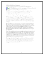
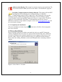
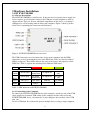
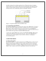
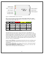
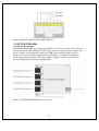
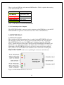
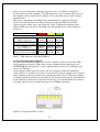
Installation instructions for Micro
Blackbox Voice Recorder on
customers own machines
This manual and the information it contains may not, in whole or in part, be reproduced,
copied, transmitted, saved in a data processing system or translated into any other
language without the written permission of the manufacturer.
This manual is for use by North Supply employees and contractors only
All trademarks mentioned in this document are the property of their respective owners.
Manual Issue :
B
Last revised on:
18.01.08
Author:
A.K.Paul
Publisher:
North Supply Ltd
Unit A3 Chartwell Point
Chartwell Drive Industrial Estate,
Wigston, Leicester.
LE18 2FL
Info:
+44 (0)116 257 1020
Support:
+44 (0)870 241 6737
Fax:
+44 (0)116 257 1030
E-Mail:
[email protected]
Internet:
http://www.northsupply.com
© 2007 • North Supply Ltd
2
1 Software Installation
1.1 Running the Installation Program
Please install the software before you attach the device to the computer. During software
installation the device driver is copied to the computer’s hard-disk.
Figure 1: Select Components to install
1.1.1 Getting Started
When you load the CD into your computer the installation program should be
started automatically. If the program has not been started after a short while, run
the installation program manually by doubling-clicking the BANNER icon (banner.
exe) in the “Startup” folder on the installation CD.
Only one program can be selected and installed at a time. Follow the on-screen
installation instructions of the chosen program from start to finish. Using the installation
assistant (see figure 1) you can then select another program for installation.
Not all of the software components (programs) must be installed in order to
use the device. You will find some commentaries about the software components in
the following paragraph.
The BT EVR software, Adobe Acrobat and the system setup must be run and installed on
all systems.
3
1.1.2 Selectable Software Components
You have the choice to install one or more of the following components:
BT EVR USB Software: includes the components Call Browser, Restricted
Browser, Call Recording Service and Demo Files.
• The Call Browser is a software solution that has been developed to allow:
– the selection of recorded calls for play-back, deletion or archiving,
– the ability to sort and to filter data according to certain criteria,
– the ability to listen into telephone conversations, and
– the calculation telephone charges by exporting comma-separated lists.
–
The Microsoft program ".Net" is required to run the Call Browser, and will
be installed if you choose to install the Call Browser. The Call Browser is not
necessary to record data, but it will be the application that you use most to find,
listen to and manage your calls. If you do not wish to install the Call Browser,
you can also retrieve the recorded data directly from the target directory to play
or analyse it.
• Restricted Browser is a reduced version of the software solution Call Browser.
This software component will only show the saved conversations for a specific
amount of time. The protocol data and configurations dialogue are not accessible
by the user of this version. The installation of Restricted Browser makes
sense when the reduced viewing and use of the saved call data is sufficient for
subsequent evaluation or when the user should only be allowed access to a part
of a conversation.
• The Call Recording Service is necessary for the recording and storage of data. It
must be selected upon installation of the BT EVR USB software on a computer
to which the BT EVR USB device is connected. If the BT EVR USB software is
being installed on a computer which will only be used for the evaluation of saved
data and to which no BT EVR USB device is connected, then the installation of
the Recording Service is not absolutely necessary.
• Recordings of the B and D channels, speech data and CDR data are available
as Demo Files for test purposes. These files are not required for the device to
function and do not have to be installed. If you have only obtained the software
without the actual device then installing the demo files could be useful for
carrying out evaluation of the software.
4
GoldWave Wave-Editor: GoldWave is a WAV editor that allows you to play
and process speech files.
The installation CD comes with a shareware version of this software, which is limited to
150 operations per session and a maximum of 3000 operations in total. You can obtain a
full licence for GoldWave either from innoventif Ltd. or directly from GoldWave Inc.
Further information about this program available on the GoldWave homepage
www.goldwave.com. This program can be used to convert speech files from WAV
format into MP3 format and thereby compress them. However, WAV files can also be
played with the Microsoft Media Player, so it is not essential to install GoldWave.
It may happen that although GoldWave has been installed, the WAV files open
automatically in the Microsoft Media Player. You can change this by right-clicking on
one of the WAV files, moving the cursor to "Open With" and choosing "GoldWave"
from the list of programs. Checking the box marked "Always open file with this
program" will ensure that in future all WAV files will be opened and played with
GoldWave.
Lame MP3 Converter: The installation of the Lame Converter is optional, but
useful .
If you want to use the program GoldWave. The LameConverter makes it possible
to convert WAV files into MP3 files in GoldWave.
Wireshark Protocol Analyser: The BT EVR USB software can produce trace
files readable byWireshark.
Wireshark is a network analysis software that allows you to decode packets or messages
used by various protocols. Wireshark is available for a number of platforms and is
covered by the GNU public license, which can be found on the CD. The source code
forWireshark can be found free of charge at ww.wireshark.org.
You only need to install Wireshark if you intend to analyse network communications.
It is not required for call recording and playback. To install Wireshark, run
wireshark-setup-x.y.z.exe (where x.y.z denotes the version number) on the installation
CD. After selecting an installation directory the necessary files will be copied to
harddisk.
Trace files use the file extension *.TRC by default. If you double click on such a
file, you will be asked with which program it should be opened. Select Wireshark
and check the “Always open file using this program” box to associate Wireshark
with *.TRC files in the future.
Network protocol analysis requires a basic understanding of computer communications.
If you are not an expert on computer networks we recommend to not install
Wireshark, as this will save disk space.
5
Adobe Acrobat Reader: This manual can also be found on the installation CD.
To read the manual in PDF you need to run Adobe’s Acrobat Reader program.
Branding, Commissioning and desktop shortcuts: This option will install BT
branding to the PC backing up any existing branding to C:\brandbu.
Commissioning software will be copied to C:\ and a batch file created on the
desktop to run the commissioning program. The folders C:\Service\Library will be
created and the Service log & manuals copied to C:\Service. A copy of the CD will be
copied to C:\Service\Library. The folder C:\VoiceDataLite will also be created.
Shortcuts to the Service log, manuals, notepad, services and www.logmein123.com will
be created on the desktop.
1.1.3 Completing the Installation
Close the installation assistant using the
have been installed.
button once all of the selected programs
1.2 Driver Installation
Please install the software first before you attach the device to your PC. During the
software installation the device driver is copied to the hard disk. The device should be
detected by Windows after you had connected it to you computer. If the device is not
detected, either a driver is already installed or there is a problem with the hardware.
Please check the cabling, Windows version and USB port before contacting technical
support.
Figure 2: Select Driver’s Location
6
If the device has been detected, Windows will search its driver database for a
known driver for the newly detected hardware. Since the device is not yet known
to Windows, it will request a driver. Select “Search for a suitable driver” and click
“Next”. You will then be asked to specify the location of the driver, as shown in figure
2. Please select the directory where the software has installed and let Windows search
this folder for a driver information (INF) file. When the driver has been selected
Windows may warn you about the absence of a digital signature. Please click “Next” or
“Continue with Installation” to proceed. Windows will complete the installation of the
driver and may request a restart. If asked to do so, please restart the computer before
continuing with the software installation.
7
2 Hardware Installation
2.1 BT EVR USB-BRI
2.1.1 Device Description
The BT EVR USB-BRI is a small device. It does not need a separate power supply, the
device requires very little power and uses the USB port of your computer to draw its
supply current. There are no user adjustable components on the device, everything is
configured by call-recording software from your computer. Figure 3 shows a picture
of the device explaining the connectors and indicators.
Figure 3: BT EVR USB-BRI Device Overview
The USB Connector is used to connect the device to the computer and the ISDN
connectors are used to attach the device to the ISDN line. There are four bi-coloured
LEDs5 (red/green). These LEDs indicate the state of the device and properties of the
ISDN line. Table 1 explains the meaning of the different LED states.
Led
TE/B2
NT/B1
Layer 1
Power
Off
Red
Yellow
Green
No TE signal
TE Signal
Polarity Error
TE Signal OK
B2 Active
(call)
No Nt signal
NT Signal
Polarity Error
NT Signal OK
B1 Active
(call)
No Layer 1
Device off
Layer active
USB Xfer
Layer 2Active
No Line
Emergency Power ISDN power
Power
Table 1: LED Indicators of BT EVR USB-BRI
2.1.2 Connecting to the Computer
To connect the BT EVR USB-BRI Device to the computer, attach one end of the USB
cable supplied to an unused USB socket on the computer and the other end to the
BT EVR USB-BRI device. Alternatively, if your computer does not have a free USB
port, you
can use a USB hub. If you intend to operate multiple devices using a single computer,
8
install the software first and then attach one device. When the software is running,
attach the other devices and they will be detected automatically and numbered by the
software in order of their detection. If all devices are attached before the software is
running, then the device numbering depends on USB Bus arbitration.
Figure 4: Assignment of RJ45 Socket for ISDN-2 Lines
2.1.3 Connecting to the ISDN-Bus
The BT EVR USB-BRI passively monitors the signals of the ISDN S0-bus. To achieve
this, the device must be connected to the bus. To do that, the device has two identical
RJ45 sockets, either of which can be used to connect the device to the ISDN line.
Because there are two sockets, no additional patch panel is required to add the device to
the bus. Follow the steps below to install the ISDN connection:
• Connect the supplied ISDN cable to either of the BT EVR USB-BRI’s RJ45 sockets.
• Then connect the other end of the lead to the spare socket on the ISDN NT1 box.
• Lift the receiver of the telephone: If you can hear a dial tone, everything has
been installed properly.
2.2 BT EVR USB-E1
2.2.1 Device Description
The BT EVR USB-E1 is a small recording device for ISDN primary rate lines. It does
not need a separate power supply, the device requires very little power and uses the
USB port of your computer to draw its supply current. There are no user adjustable
components on the device, everything is configured by the software on your computer.
Figure 5 shows a picture of the device explaining the connectors and indicators.
9
Figure 5: BT EVR USB-E1 Device Overview
There are four bi-coloured (red/green) light emitting diodes (LED). These LEDs
indicate the state of the device and properties of the ISDN line. Table 2 explains the
meaning of the different LED states.
Led
Off
Red
Yellow
Green
USB
No Power
USB Error
USB Active
Software
Active
Layer 1
No Layer 1
Layer 1 Active
Layer 2 Active
Layer 3
Active
NT Signal
Not Active
No Signal
NT Signal Present G.704 Signal
TE Signal
Not Active
No Signal
TE Signal Present G.704 Signal
Table 2: LED Indicators of BT EVR USB-E1
The LED indicating activity of the various protocol layers of the ISDN gives an
indication of the state of the E1-line. If there is no layer 1 activity, there is a physical
problem with cabling or synchronization. If the layer 1 is active, but there are no data
frames the LED stays red. If protocol frames (layer 2 activity) are detected, the LED
turns orange. Finally, if there are calls active (i.e. in connected state) the LEDs colour
will be green. The NT-signal and TE-signal LEDs help to locate problems if there is
no layer 1 activity or synchronization.
Layer 1 active (LED red): A functioning connection to the nearest switching centre
has been established. Both communication end-points send a correct signal and are
synchronized.
Layer 2 active (LED yellow): An exchange of data packets is taking place through
this connection and the line is available for use.
Layer 3 active (LED green): Telephone calls are currently active on this line. This
could mean one call or up to 30 calls simultaneously.
10
2.2.2 Connecting to the Computer
To connect the BT EVR USB-E1 device to your computer, attach one end of the USB
cable supplied to an unused USB socket on your computer and the other end to the
BT EVR USB-E1 . If you intend to operate multiple devices using a single computer,
install the software first and then attach one device. When the software is running,
attach the other devices and they will be detected automatically and numbered by the
software in their order of detection. If all devices are attached before the software is
running, then the device numbering depends on USB Bus arbitration.
Please note that you should not use a USB hub with the BT EVR USB-E1 . The
BT EVR USB-E1 is using more than 50% of the available bandwidth of an USB 1.1
interface. If multiple devices should be operated on the same computer please make
sure that each device is connected to a different USB host controller. Neighbouring
USB ports on a mainboard are often connected to the same USB host controller via an
USB root. No two BT EVR USB-E1 devices may be connected to the same USB host
controller due to the high rate of data transfer. If problems should arise with the operation
of more than one E1 devices on one PC, we recommend that you try different
USB ports or different combinations of connections.
2.2.3 Connection to the ISDN Line
The BT EVR USB-E1 monitors the ISDN E1-line passively, or with high impedance.
The device has two identical RJ45 sockets, one of which can be used to connect the BT
EVR USB-E1 to the ISDN line. There will be an RJ45 cable connecting the Phone
system to the NTE it will be necessary to disconnect one end of this cable (Which ever is
the most convenient). A Y adaptor plugged in and to the empty socket and the RJ45 lead
re-plugged in. Make a call to check the connection is OK and then connect the BT EVR
USB-E1 to the other socket in the Y adaptor.
Unfortunately, different sockets and cables are used for the E1 or S2M connectors.
If your system still uses asymmetrical cabling with 2 coaxial cables with 75 Ohm
characteristic impedance, you will require two T-junctions and an adaptor (coaxial to
RJ45, balun). These components are available as accessories.
The standard pinning for the balanced variant of the E1/S2M connectors uses an RJ45
connector and a cable with 120 Ohm characteristic impedance, in which pins 1 and 2, 4
and 5 are each assigned a pair (Figure 6). The BT EVR USB-E1 uses this pinning as
standard.
The protocol resynchronization may take a while (up to 15 minutes), but unfortunately
it is difficult to tell in this state whether the resynchronization is taking
place or whether the device has been cabled wrongly. However, one can see on
the BT EVR USB-E1 device whether or not the TE and NT pairs are receiving a
signal with the correct G.704 framing. If this is the case, the device has been cabled
correctly and the line will resynchronize itself. Interrupting the line causes
a link alarm in the central office which will be reset after a certain period of time.
11
Figure 6: Balanced RJ45 Socket for ISDN-30 Lines
3.3 BT EVR USB-4SBx
3.3.1 Device Description
The BT EVRUSB-4SBx is a recording box which is used as an external device. The box
will be connected to the USB port of a PC. Does not need a separate power supply, the
devices require very little power and use the USB port to draw the supply current.
There are no user adjustable components on the hardware, everything is configured
by the call-recording software from your computer. Figure 7 shows a picture of the
device explaining the connectors and indicators.
Figure 7: BT EVR USB-4SBx Device Overview
12
There is only one LED for each connected BRI interface. Table 4 explains the meaning
of the different LED states.
LED
Green Blinking
State Display
Red Blinking
Device Power, USB
Xfer
Not enabled
Red Permanent
Yellow Permanent
Green Permanent
Layer 1 active
Layer 2 active
Layer 3 active
Table 3: LED Indicators of BT EVRUSB-4SBx
2.3.2 Connecting to the Computer
The BT EVRUSB-4SBx is connected to the computer and the ISDN lines as per the BT
EVR USB-BRI except that 4 connections have to be made to the ISDN lines.
2.4 BT EVRUSB-A2
2.4.1 Device Description
The recording of data from analogue lines is enabled by the BT EVRUSB-A2 device.
The analogue recording device gets its power from the USB port of your computer.
The BT EVRUSB-A2 decodes the DTMF and V.23 Modem signalling (ETS-300659-1). So that the device detects the Caller-ID (Caller Identification) and further dial
information (e.g. called party number) and displays them in Call Browser, if present.
Furthermore, the BT EVRUSB-A2 device can also be connected to other analogue
lines, such as a taxi or household radio. With this sort of connection recording takes
place by voice activation.
Figure 8 shows a picture of the device explaining the connectors and indicators.
Figure 8: BT EVRUSB-A2 Device Overview
13
There are no user adjustable components on the device, everything is configured
by the software on your computer. The USB connector is used to connect the device to
the computer and the connector line A/B are used to attach the device to the analogue
telephone lines.
The device can monitor two analogue lines simultaneously, using the connectors
for line A and line B. There are four bi-coloured (red/green) LEDs. These LEDs
indicate the state of the device and of the line. Table 4 explains the meaning of the
different LED states for line A. The LED states for line B have the same meaning as
for line A.
Led
Red
Yellow
Green
Line A
Power / Ring Pulse
Line A
Off Hook, Caller ID, Recording
Line B
Power / Ring Pulse
Line B
Off Hook, Caller ID, Recording
No Line
Power
Caller ID
Detected
No Line
Power
Caller ID
Detected
Ring Pulse
Present
Telephone
is off Hook
Ring Pulse
Present
Telephone
is off Hook
Line is
Powered
Recording
Call
Line is
Powered
Recording
Call
Table 7: LED Indicators of BT EVRUSB-A2
2.4.2 Connecting to the Computer
To connect the BT EVRUSB-A2 tester to your computer, attach one end of the USB
cable supplied to an unused USB socket on your computer and the other end to the
BT EVRUSB-A2. Alternatively, if your computer does not have a free USB port, you
can use an USB hub.
Your computer should detect the device and you can proceed with the installation
of the software as described in section 1. If you intend to operate multiple devices using a
single computer, install the software first and then attach one device. When the software
is running, attach the other devices and they will be detected automatically and numbered
by the software in their order of detection. If all devices are attached before the software
is running, then the device numbering depends on USB Bus arbitration.
Figure 9: Assignment of RJ11 Socket
14
2.4.3 Connecting to an analogue Line
Use the cables you received together with the device to connect the BT EVRUSB-A2
to the telephone lines. Each RJ11 Western Modular Socket at the device can be use to
monitor one analogue phone line. A RJ11 socket has six PINs. PIN 3 and PIN 4 are
connected with both lines (Tip and Ring) of the analogue telephone interface.
2.5.1 8 Line analogue Device
An 8 line USB analogue adaptor will be available that’s looks similar to the 4 line BRI
device each RJ45 socket will support 2 lines. These will be on pins 3 & 4 and pins 6 & 7,
special cables will be supplied comprising 1 RJ45 plug to 2 RJ11 plugs.
Figure 10: Assignment of RJ45 socket
15
Important installation considerations.
•
To allow remote access to the recordings from a network PC the Call Browser needs to be
installed on the remote PC and pointed the shared VoiceDataLite folder on the Main VR. It should
be remembered that once this folder is shared calls can be accessed by anyone on the network as
the calls are stored in a .wav format and can be played on any PC, also the file names contain all
the date, time and number data. It is possible to encrypt the calls but this is extremely non user
friendly requiring the pass key to be entered every time a call is played back.
•
It is not advisable to set the voice data limit any higher than 80 GB it will become very slow. (This
recommended figure will be subject to change).
•
When the VoiceDataLite folder begins to fill up it is recommended that the customer turns off the
auto refresh.
•
Pre-install site surveys will be conducted by the customer with help from a NS Technician. It is
recommended that the VR be no more than 2 metres from the Lines/phone system. With BRI it
can be more but it must be remembered that cable may need to be run. However with analogue it
does not matter what the distance is (within reason) but as with BRI cable may need to run which
may not have been costed as this is a budget system.
•
If it absolutely impossible to get around the 2 metre limit it is possible to extend the USB over a
CAT5 cable up to around 20 metres. With the 4 Port BRI & 8 Port analogue a powered USB hub
will be required at the logger end.
•
When installing on Windows Vista if the current login does not have full permission to write to
the local hard drive the software will appear to install OK but nothing will write and the shortcuts
will not be found. Ask the customer to login as an administrator and re-install. The system will
always need to write to the local drive obviously to store calls.
16